EP3091827B1 - Saatscheibe mit integriertem antrieb - Google Patents
Saatscheibe mit integriertem antrieb Download PDFInfo
- Publication number
- EP3091827B1 EP3091827B1 EP15734867.3A EP15734867A EP3091827B1 EP 3091827 B1 EP3091827 B1 EP 3091827B1 EP 15734867 A EP15734867 A EP 15734867A EP 3091827 B1 EP3091827 B1 EP 3091827B1
- Authority
- EP
- European Patent Office
- Prior art keywords
- seed
- motor
- disc
- meter
- seed disc
- Prior art date
- Legal status (The legal status is an assumption and is not a legal conclusion. Google has not performed a legal analysis and makes no representation as to the accuracy of the status listed.)
- Not-in-force
Links
- 230000008901 benefit Effects 0.000 description 11
- 230000004907 flux Effects 0.000 description 9
- 230000010354 integration Effects 0.000 description 9
- 239000011236 particulate material Substances 0.000 description 8
- 230000009467 reduction Effects 0.000 description 6
- 239000000696 magnetic material Substances 0.000 description 5
- 239000000463 material Substances 0.000 description 5
- 230000007246 mechanism Effects 0.000 description 3
- 238000000034 method Methods 0.000 description 3
- 238000004804 winding Methods 0.000 description 3
- 241000196324 Embryophyta Species 0.000 description 2
- CWYNVVGOOAEACU-UHFFFAOYSA-N Fe2+ Chemical compound [Fe+2] CWYNVVGOOAEACU-UHFFFAOYSA-N 0.000 description 2
- 244000068988 Glycine max Species 0.000 description 2
- 235000010469 Glycine max Nutrition 0.000 description 2
- 240000008042 Zea mays Species 0.000 description 2
- 235000002017 Zea mays subsp mays Nutrition 0.000 description 2
- 230000008859 change Effects 0.000 description 2
- 239000000203 mixture Substances 0.000 description 2
- 235000012771 pancakes Nutrition 0.000 description 2
- 238000009987 spinning Methods 0.000 description 2
- 230000001360 synchronised effect Effects 0.000 description 2
- 229920000049 Carbon (fiber) Polymers 0.000 description 1
- 229920000742 Cotton Polymers 0.000 description 1
- 241000219146 Gossypium Species 0.000 description 1
- 229910000831 Steel Inorganic materials 0.000 description 1
- 235000005824 Zea mays ssp. parviglumis Nutrition 0.000 description 1
- 241000482268 Zea mays subsp. mays Species 0.000 description 1
- 230000009471 action Effects 0.000 description 1
- 230000004323 axial length Effects 0.000 description 1
- 230000015572 biosynthetic process Effects 0.000 description 1
- 239000004917 carbon fiber Substances 0.000 description 1
- 230000004456 color vision Effects 0.000 description 1
- 238000004891 communication Methods 0.000 description 1
- 238000010276 construction Methods 0.000 description 1
- 235000005822 corn Nutrition 0.000 description 1
- 230000003247 decreasing effect Effects 0.000 description 1
- 239000000428 dust Substances 0.000 description 1
- 230000005611 electricity Effects 0.000 description 1
- 230000004438 eyesight Effects 0.000 description 1
- 239000003337 fertilizer Substances 0.000 description 1
- 239000012530 fluid Substances 0.000 description 1
- 230000006698 induction Effects 0.000 description 1
- 239000002917 insecticide Substances 0.000 description 1
- 238000009434 installation Methods 0.000 description 1
- 238000000465 moulding Methods 0.000 description 1
- 230000000149 penetrating effect Effects 0.000 description 1
- 230000008569 process Effects 0.000 description 1
- 230000001681 protective effect Effects 0.000 description 1
- 230000007420 reactivation Effects 0.000 description 1
- -1 seed Substances 0.000 description 1
- 239000002689 soil Substances 0.000 description 1
- 239000010959 steel Substances 0.000 description 1
Images






Classifications
-
- A—HUMAN NECESSITIES
- A01—AGRICULTURE; FORESTRY; ANIMAL HUSBANDRY; HUNTING; TRAPPING; FISHING
- A01C—PLANTING; SOWING; FERTILISING
- A01C19/00—Arrangements for driving working parts of fertilisers or seeders
- A01C19/02—Arrangements for driving working parts of fertilisers or seeders by a motor
-
- A—HUMAN NECESSITIES
- A01—AGRICULTURE; FORESTRY; ANIMAL HUSBANDRY; HUNTING; TRAPPING; FISHING
- A01C—PLANTING; SOWING; FERTILISING
- A01C7/00—Sowing
- A01C7/04—Single-grain seeders with or without suction devices
-
- A—HUMAN NECESSITIES
- A01—AGRICULTURE; FORESTRY; ANIMAL HUSBANDRY; HUNTING; TRAPPING; FISHING
- A01C—PLANTING; SOWING; FERTILISING
- A01C7/00—Sowing
- A01C7/04—Single-grain seeders with or without suction devices
- A01C7/042—Single-grain seeders with or without suction devices using pneumatic means
- A01C7/044—Pneumatic seed wheels
- A01C7/046—Pneumatic seed wheels with perforated seeding discs
Definitions
- the invention relates generally to agricultural implements for planting seed. More particular, but not exclusively, the invention relates to a seed disc and meter of a planter having an integrated motor to reduce the width of the seed meter and to provide a row unit for the planter with varying configurations.
- An agricultural row crop planter is a machine built for precisely distributing seed into the ground.
- the row crop planter generally includes a horizontal toolbar fixed to a hitch assembly for towing behind a tractor. Row units are mounted to the toolbar. In different configurations, seed may be stored at individual hoppers on each row unit, or it may be maintained in a central hopper and delivered to the row units on an as needed basis.
- the row units include ground-working tools for opening and closing a seed furrow, and a seed metering system for distributing seed to the seed furrow.
- the seed meter includes a housing and a seed disc.
- the housing is constructed such that it creates a reservoir to hold a seed pool.
- the seed pool may also be in a separate structure.
- the seed disc resides within the housing and rotates about a generally horizontal central axis. As the seed disc rotates, it passes through the seed pool where it picks up individual seeds. The seeds are subsequently dispensed into a seed chute where they drop into the seed furrow.
- Seed spacing in the seed furrow is controlled by varying the rotational speed of the seed disc.
- seed disc rotation is driven by connection to a common driveshaft.
- the driveshaft runs horizontally along the length of the toolbar to connect to each row unit, and is driven by a single motor or a ground contact wheel.
- the planting rate can be adjusted for all row units uniformly by adjusting the rotational speed of the common drive shaft. This can be a tedious task, and an operator is unlikely to adjust the gear ratio as often as necessary to maximize yields.
- an optimal overall rate for a given acreage will be selected prior to planting and will be maintained at that rate regardless of soil conditions.
- the seed disc is installed inside of the seed meter using independent fasteners and requires the use of tools to facilitate changing the disc. For example, if a farmer uses the same planter to plant corn and soybeans, he would use a different disc for the respective seed types. With planters continuing to grow in size, and more row units being added, the task of changing seed discs using independent fasteners and tools adds unnecessary burden to changing out seed discs.
- the meters include a motor, such as an electric motor, that is attached to the meter.
- a motor such as an electric motor
- a DC brushless motor can be utilized, which includes an output shaft. The output shaft extends from the motor and into the meter such that a portion of the shaft is operatively connected to the seed disc. Therefore, the motor will operate to rotate the seed disc.
- the electric motor when electrically driving seed meters, the electric motor must either directly drive the seed disc via a hub or other connection method.
- the motor being used is placed axially and is detached from the seed disc, which increases the axial width of the seed meter.
- This setup makes motor removal and installation difficult.
- Another method is to transfer power to the seed disc through gears, belts, or other power-transmitting means, which.allows the motor to be placed in a more suitable location and making it easier to service.
- a seed meter including a seed disc that has a smaller width than that of a seed meter being driven by an external, electric drive motor.
- a meter that includes a modular-type disc driving motor that can be quickly attached to different seed discs used to distribute and plant different types of seed.
- WO 2012/142558 A1 discloses an integral seed meter drive motor.
- a metering device includes a metering chamber containing a metering disc rotatable therein.
- the metering disc has a plurality of seed pockets for carrying seed.
- the metering disc has a magnetic drive ring.
- the metering device has a stator positioned adjacent the metering disc. The stator interacts with the magnetic drive ring to rotate the metering disc in use.
- a seed disc according to claim 1 includes incorporating a large diameter motor with a narrow axial width into communication with a seed disc.
- a reversed armature arrangement is utilized such that the output shaft (inner member) of the motor is fixed and the outside of the motor is allowed to spin.
- the outside of the motor can form a quick attach hub, in which a seed disc ring is attached. This allows for the motor to be enclosed inside the protective environment of the seed meter housing, and provides open access to service the motor. In this case, the inner member of the motor becomes the stator and the outer member of the motor becomes the rotor.
- the motor may be a brushless DC motor, or may even be a brushed DC motor. Some embodiments contemplate the use of a stepper motor. Furthermore, additional embodiments contemplate the addition of magnets or magnetic materials within the circular member of the seed disc itself, in which the seed disc becomes the rotor of the motor assembly.
- the motor can be integrated with the seed disc such that a portion of the seed disc surrounds or is otherwise positioned around at least a portion of the circumference of the motor. Alternatively, the motor can be positioned such that it is adjacent or otherwise at least partially surrounding a portion of the seed disc including the seed cells and/or seed path. However, the integration of the motor and seed disc can provide that the two are combined such that they comprise a single unit, which may include multiple components.
- the motor includes members that rotate the seed disc through bearing members surrounding a lip portion of the seed disc.
- the seed disc may be magnetically levitated within the system to position the seed disc.
- aspects of the invention include the use of a single stator or inner portion of a motor that is used to power separate rotors of separate seed discs.
- the single rotor would act upon the magnets of the separate rotor portions operatively attached to the seed disc to cause one or both of the discs to rotate at a time. This would allow multiple meters to be used at each row unit, which would enable multiple hybrids of particulate material to be planted.
- Still other aspects of the invention include the integration of a fan into either a single meter housing or between meter housings.
- the fan could replace air hoses, and can be used to provide a pressure differential, either positive or negative, at the seed cells of the seed discs to urge seed or other particulate material to be held at and against the seed disc.
- the fan can be positioned either coaxially with the seed disc or at another location and attached to the seed meter housing.
- the use of the integrated fan and motor would greatly reduce the width of the seed meter, which would provide for numerous applications. For example, reducing the width could allow for multiple seed meters to be positioned at each row unit to provide for different applications of particulate materials.
- the meters could also be moved closer to the ground to release seed or other materials at a location close to the ground, which would enhance seed spacing, depth, and other planting characteristics.
- the invention could also result in the removal of many parts of standard seed meters, which reduce the complexity of the meters, number of components, and thus, number of components that would need replacing, maintained, or otherwise, while increasing the durability.
- FIG 1 is a perspective view of an exemplary embodiment of an agricultural implement 10, which is shown as a planting implement. Such a planter 10 is further shown and described in U. S. Patent Application No. 13/927,177 .
- Figure 1 shows the planter 10 with a tongue 12, which may be a telescoping tongue when the planter 10 is a forward folding planter.
- a hitch 16 is positioned at the first end 14 of the tongue 12, and is used to attach the planting implement 10 to a tractor (not shown) or other vehicle for pulling the planting implement 10.
- the tongue 12 is a telescoping tongue, it may be aided by the addition of draft links 22 on opposite sides of the tongue 12.
- the draft links 22 connect the tongue 12 to first and second wings 32, 36, such that when the wings fold by operation of cylinders 18, the supports 22 will extend or retract sections of the telescoping tongue 12 to lengthen or shorten the tongue 12 so that the wings 32, 36 are able to be folded adjacent one another and the tongue 12.
- a main or central frame 18, Positioned at or near a rear end of the tongue 12 is a main or central frame 18, which may also be known as a toolbar.
- the main or central frame 18 extends generally perpendicular to the tongue 12.
- the central frame 18 also includes structure for central hoppers 26.
- the main hopper 26 which may also be known as bulk fill hoppers, central hoppers, or other tanks, house materials, such as seed, insecticide, fertilizer, or the like, which is distributed through a system to individual row units on the frame and wings.
- the bulk fill hoppers may be operably connected to an air seed delivery system for delivering seed from the bulk fill hoppers to individual row units.
- an air seed delivery system is disclosed in U. S. Patent No. 8,448,585 .
- the central fame includes a plurality of central row units extending from the rear of the frame to distribute the material to a field.
- the central frame also includes an axle and transport wheels 30 extending from the frame.
- the transport wheels 30 support the main or central frame and are also the wheels that contact the ground when the implement 10 is transported to or from a field.
- first and second wings 32, 36 Extending from opposite sides of the central frame or main frame 24 are first and second wings 32, 36.
- the first and second wings 32, 36 generally mirror one another, and therefore, only one wing will be described. It should be appreciated that opposite wing 36 is generally the same components.
- the first wing 32 includes a first frame 34 extending separate from, but extending generally in the same plane as the main frame 24.
- a plurality of row units is connected to the first frame 34.
- the row units of the first wing 32 are generally the same as the row units of the main frame 24 and that of the opposite wing 36, which extend from the second wing frame 34.
- the number of row units with implement 10 may vary depending on the size of the implement 10, the requirements of the field, type of field, the type of material being distributed to the field, and the like.
- wing wheels 38 also extending from the wing frame 34.
- the wing wheels 38 support the wings 32, 36 and allow the implement 10 to be moved without the row units penetrating the ground when
- the implement 10 includes a plurality of row units 40 extending from the wings 32, 36 and the central frame 24.
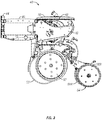
- a conventional planter row unit 40 with an air seed meter 42 positioned therewith is shown in Figures 2 and 3 .
- the seed meter may utilize negative or positive pressure caused by air to retain and transport seed.
- the row unit 40 and air seed meter 42 may be of the kind shown and described in U.S. Patent Application No. 13/829,726 .
- the invention contemplates other types of seed meters, including mechanical, brush, finger, or the like, which may be used with the present invention.
- the row unit 40 includes a U-bolt mount for mounting the row unit 40 to the planter frame or tool bar (on central frame and wings), as it is sometimes called, which may be a steel tube of 5 by 7 inches (127x178 mm) (although other sizes are used). However, other mounting structures could be used in place of the U-bolt.
- the mount includes a face plate 44, which is used to mount left and right parallel linkages 46. Each linkage may be a four bar linkage, as is shown in the figures.
- the double linkage is sometimes described as having upper parallel links and lower parallel links, and the rear ends of the parallel links are pivotally mounted to the frame 48 of the row unit 40.
- the frame 48 includes a support for the air seed meter 42 and seed hopper 50, as well as a structure including a shank for mounting a pair of ground gage wheels 58.
- the frame 48 is also mounted to a closing unit 54, which includes a pair of inclined closing wheels 56A, 56B.
- the row unit 40 also includes a pair of opener discs 53. While the row unit 40 shown in Figures 2 and 3 is configured to be used with a bulk fill seed system, it is to be appreciated that the row unit 40 may have one or more row hoppers 50 at each of the row units 40. Exemplary versions of row units with individual hoppers is shown and described in U.S. Patent Application No. 14/176,198 .
- the implement 10 and row units 40 shown and described in Figures 1-3 include an air seed meter 42 for singulating and transporting seed or other particulate material from the seed delivery source to the created furrow in the field prior to the closing wheels 56 closing said furrow.
- An aspect of the present invention includes a novel seed meter 60 including a seed disc assembly 64, such as that shown in Figures 4-6 .
- Previous seed meters 60 have used various types of drive systems to rotate the seed disc 64 of the seed meter 60 in order to singulate and transport the seed or other particulate material via the seed meter 60 to the ground, such as in a trench formed in the ground.
- Some such systems include direct drive systems in which a chain or other member is operatively connected to one or more wheel axles for rotating approximately the same ground speed of the wheels.
- Still others have included the use of an electrical drive motors positioned at each seed meter in order to drive the seed disc of the meter via an output shaft of the motor.
- Such a situation includes mounting of a motor adjacent or to the seed meter 60 with the output shaft extending into the seed meter 60 and into contact with the seed disc 64 to drive the seed disc 64 in a rotational manner.
- previous electrical motors include DC brushless motors, which require numerous gear reductions within the motor, which cause the size of the motor to increase.
- the motor must be configured and sized such that the size of the motor causes the size of the seed meter to be wide, which takes up a great deal of the space of the row unit.
- Brushless DC motors generally include a rotor and a stator.
- the outer member of the motor is generally referred to as the stator, as it is generally stationary during operation of the motor.
- the stator includes magnets that are wound with electric coils, in which an electric current can be passed therethrough to operate the motor.
- At the interior of the motor is a permanent magnet with opposing poles. Electricity is passed through the wires winding around the magnets of the stator, which cause rotation of the permanent magnet of the rotor. This rotation can then be transferred via gears and other transferring mechanisms to provide rotation of an output shaft.
- the housing of the brushless DC motor must be rather large in order to house all of the components of the brushless DC motor.
- the present invention contemplates the use of a novel configuration of a brushless DC motor in which the rotor, which may also be referred to as an armature, and the stator are reversed.
- the reversal of the armature and the stator house different components of the motor to rotate upon actuation of the motor, which will provide many unique and advantageous benefits to a seed disc used in a seed meter.
- the invention contemplates the reversal of the rotor 70 and stator 68 of the brushless DC motor, which then may be integrated with the seed disc 64 itself.
- This integration of the motor 66 and the seed disc 64 provides a motor 66 that can be housed within the seed meter housing 62, along with the seed disc 64 itself.
- the combined seed disc and motor may form an integrated, one-piece unit, or can be multiple components combined to interact with one another. This eliminates the need of an external drive mechanism for the seed meter 60, protects the motor 66 from many external elements, and greatly reduces the width required for seed meter 60, which allows for many variations to be made to the components of a row unit 40, which have been heretofore unforeseen in the agricultural industry.
- Such exemplary applications for a seed meter 60 including a seed disc 64 with an integrated motor 66 within a seed meter housing 62 will be shown and described.
- Figures 4-6 illustrate one aspect of a seed meter 60 including a motor 66 integrated with a seed disc 64.
- the term integration does not require that the motor be within the outer profile or within the circumference of the seed disc 64. Instead, the term can be used to describe an assembly in which the motor 66 of the seed disc 64 is directly driving the seed disc 64 in a manner in which the motor 66 is directly or otherwise operatively attached to the seed disc 64 or otherwise included as part of the seed disc 64 and, in some embodiments, all within the seed meter hosing 62.
- a seed meter 60 includes a housing 62 for substantially surrounding a seed disc assembly 64.
- the seed disc assembly 64 includes a generally circular seed disc member 72, which is able to rotate within the seed meter housing 62 to attach a seed or other particulate material at a seed cell 74 to distribute the seed or other particulate material to the ground.
- the circular member 72 includes a plurality of seed cells 74 radially spaced from a central axis thereof and forming a seed cell path 76 through which the seed cells 74 will rotate.
- the circular member 72 of the seed disc 64 is a generally ring-shaped disc with an aperture or other hollow interior portion.
- a motor 66 Positioned within the open area of the ring-shaped seed disc member 72 is a motor 66 for providing a rotational drive mechanism to the seed disc 64.
- the motor 66 shown in the figures may be a brushless DC motor.
- the components of the motor 66 have been reversed such that the inner member 68 is substantially stationary, and may be referred to as a stator 68, while the outer portion 70 may be referred to as the rotor 70 or armature, and is capable of rotating relative to the inner member 68. Therefore, it is contemplated that the magnets and windings of the inner and outer members 68, 70 may be reversed to provide that a current supplied to the motor 66 will cause the rotation of the outer member 70 relative to the generally stationary inner member 68.
- the inner member 68 may then be attached to or otherwise affixed within the seed meter housing 62 in such a way that the outer member 70 is able to rotate relative to the inner member, while keeping the motor 66 generally in place within the housing 62
- the motor 66 may be attached to the ring-shaped seed disc member 72 via attachment member 78, 80 of the motor 66 and seed disc member 72.
- the assembly shown in Figures 4-6 may be generally modular in nature, such that different seed disc members 72 can be attached to a common motor 66 to provide for the planting of various seed types.
- different seed types such as corn, soybean, sweet corn, cotton, and the like, have varying sizes, shapes, and planting requirements and/or characteristics.
- the seed cells 74 and seed paths 76 are varied according to the type of seed in which the seed disc member 72 is to be used for planting. Therefore, another aspect of the invention provides for a common motor 66 to be used with differing seed disc members 72, which are configured to be used with the varying seed types.
- the motor includes outer attachment members 78, while the ring-shaped seed disc member 72 includes its own attachment members 80.
- the attachment members 78, 80 may be slidingly or otherwise engaged to one another such that the motor 66 is positioned with matching slots and openings, and then rotated to lock the motor 66 into connection with the disc member 72.
- the motor 66 can be quickly rotated to disengage with the disc member 72, and to allow for reengagement of a separate seed disc member 72.
- the embodiments shown may be generally modular in nature such that the seed disc assembly 64 can be quickly and easily changed to account for variations in the planting process.
- the operation of the seed disc assembly 64 will not change based on the type of seed disc 72 used with the integrated motor 66.
- the inner member 68 of the motor 66, outer member 70, and seed disc member 72 are coaxial with one another. They are coaxial about the central axis 84 of the seed disc assembly 64, within the seed meter 60.
- the inner and outer members 68, 70 of the motor 66 are configured such that the introduction of a current to the motor 66 will cause the outer member 70 to rotate about the substantially stationary inner member 68 of the motor 66.
- the seed disc member 72 will begin to rotate as well with the outer member 70 of the motor 66.
- the seed meter housing 62 may include an attachment to an air source, such as a vacuum source.
- a seed pool of distributed seed may be included within the seed meter housing 62.
- the seed disc 64 with integrated motor 66 is operated to rotate the seed disc member 72 such that the seed cells 74 pass through the seed pool (not shown).
- the air source provides a pressure differential on the opposing sides of the seed cells 74 such that the seed will become affixed at a seed cell 74 as the seed disc 64 passes through the seed pool.
- the seed meter 60 will continue rotation through a singulator (not shown), which aids in providing that only one seed be positioned at each seed cell 74.
- the meter 60 is continually rotated until a particular seed passes through a zone of no pressure differential, which dislodges the seed from the seed cell 74 of the seed disc 64.
- the seed is then passed through a chute or other member and towards a furrow, which has been created in the field.
- the seed closing wheels 56 of the row unit 40 then close the earth around the seed positioned in the seed furrow, thus planting the seed.
- an electric motor for driving the seed meter 60 provides numerous advantages over previous mechanical means for driving the seed meter 60.
- the electric motor provides for greater torque and instant action of the rotation of the seed disc 64 in the seed meter 60.
- the individual integration of the electric motor with each seed disc 64 of the seed meter 60 allows for each of the seed meters 60 to be independently operated.
- the individual operation of each seed meter allows for numerous applications for planting. For example, when certain row units 40 of a planter pass over an area not to be planted, the controls of the system allow for the shut off of particular motors of the seed meters 60, which ensures that the location will not be planted by the row units 40. However, as other row units 40 can be independently controlled, the seed meters 60 will continue to operate at said units 40.
- the independent control of the seed meters 60 by the integrated motor allows for multi seed meters 60 to be positioned at each row unit 40, such as for use with multi-hybrid planting.
- the electrically controlled motor can independently be operated to activate a particular seed meter 60 including a particular hybrid of seed, which will then plant that seed at a particular location in the field.
- the first meter 60 can be shut off via the electric motor, while the second meter 60 activated instantaneously to begin planting of the second hybrid.
- the use of the electric motors integrated with the seed disc 64 of the seed meters 60 allows for two or even more seed meters 60 to be used at each row unit 40 to provide for the ability of multi-hybrid planting of the planter unit 10.
- the motor 66 integrated with the seed disc member 72 of the seed disc 64 may include a diameter between 2-15 inches (51-381 mm), while one is more preferred being of approximately 6 1 ⁇ 2 inches (165 mm). Doing so will require a motor that is approximately 1 to 1.5 inches (25-38 mm) wide and requires approximately 1.7 amps to activate and power.
- a motor that is approximately 1 to 1.5 inches (25-38 mm) wide and requires approximately 1.7 amps to activate and power.
- other diameters, thicknesses, and energy requirements can be utilized with the invention, and can be selected based upon the requirements for planting. For example, it is contemplated that as the diameter of the motor increases, the thickness and energy required to operate will decrease. Having a motor with a width less than 1.5 inches (38 mm) will allow the motor to fit within existing seed meter housings.
- the inclusion of the motor within the housing will provide other advantages.
- the seed meter housing 62 can now be formed with decreased width due to the removal of the external motor attached to the housing. It is contemplated that the housing can be in size to approximately two inches (51 mm) wide.
- the inclusion of the motor within the seed meter housing 62 would protect the motor from external elements, such as dust and other debris. Still further, the use of the motor as shown and described will improve the efficiency of the motor as it does not include gear boxes, as previous DC electric motors have required. Other benefits include that the inclusion allows for increased diameter of the seed disc, which allows for motors to make a higher available torque at a lower speed.
- the motor has shown to be snap and rotatably fit to the ring-shaped seed disc member 72
- other types of connections between the motor 66 and the seed disc member 72 may be contemplated.
- the members may be snap fit to one another.
- the motor be permanently attached to a seed disc 64 as well.
- the invention is not to be limited to the specific ways of showing and describing the attachment between the motor and the seed disc member 72, and it is to be appreciated that any type of attachment between the motor and the seed disc 64 may be included as part of the invention.
- Figure 7 discloses an example which includes the integration of a motor 66 with a seed disc member 72 to form a seed disc assembly 64, which can be positioned within a seed meter housing 62 of a seed meter 60.
- Figure 7 discloses an assembly in which the motor 66, which may be a brushless DC electric motor, is positioned adjacent to or at least partially surrounding the outer edge of the seed disc member 72.
- the seed disc member 72 includes a generally circular member that includes a plurality of seed cells 74 forming the seed path 76, in which the seed cells 74 are radially spaced from a central axis of the circular member 72.
- the motor 76 is surrounding the seed disc member 72 or is adjacent the seed disc member 72 such that it is able to drive the seed disc member 72 about the outer portions of the disc member 72 within the seed member 60.
- the motor 66 includes an inner member 68 and an outer member 70.
- the inner member 68 in this particular embodiment may be the rotor or armature member, while the outer member be the substantially stationary stator member. Therefore, in this particular example, which does not form part of the invention, the inner member 68 includes permanent magnets, while the outer member 70 includes magnetic members with electric coils wrapped around. The introduction of power to the coils operates the motor 66 such that the inner member 68 will begin to rotate, while the outer member 70 stays substantially stationary.
- the inner member 68 of the motor 66 shown in Figure 7 will be operatively attached to the seed disc member 72, such that rotation of the inner member 68 will also cause the seed disc member 72 to rotate in unison therewith.
- the inner member 68 of the motor 66 can be attached, such as permanently or selectively affixing the inner member 68 to the disc member 72.
- the seed meter 60 may include that the inner member 68, in line with the axis of the circular member 72 be the substantially stationary stator, and the portion referenced by numeral 70 in Figure 7 be the outer armature or rotor member of the motor 66.
- the outer member 70 will extend at least partially behind the disc member 72, and be attached out the outer edge of the seed disc member 72. Therefore, while the inner portion of the motor at the axis thereof remains stationary, the outer member 70 attached to the seed disc member 72 will begin to rotate, which causes rotation of the seed disc member 72 as well.
- Figure 8 shows yet another aspect of the present invention which includes the integration of a motor 66 with a seed disc member 72 to form a seed disc assembly 64.
- the assembly 64 shown in Figure 8 includes a brushless DC motor which includes an outer rotating rotor member, which may be shown by reference 70.
- the configuration shown in Figure 8 includes the use of spinning or friction members 86 based radially about the outer edge of the seed disc member 72. The members 86 can be attached to the rotating rotor 70 of the motor 66. Therefore, when the motor 66 is activated, the outer rotor portion 70 begins to rotate about the central axis.
- the spinning or friction members 86 which contact the seed disc member 72 at three points around the outer edge of the seed disc 64, will begin to cause rotation of the seed disc member 72 about the central axis 84 as well.
- This provides a different manner in which the brushless DC motor, which includes reversed outer and inner rotor members, can be used to pause rotation of a seed disc member 72 then a seed meter 60.
- more or less than three contact points be used to aid in the rotation of the seed disc.
- Figure 9 discloses yet another embodiment of a motor 66 and seed disc member 72 assembly 64 for providing rotation of the seed disc 64 in a seed meter 60.
- the motor of Figure 9 is shown to be a stepper motor, and includes teeth portions 90 about an outer periphery thereof.
- the stepper motor is a type of DC motor that divides a full rotation into a number of equal steps. The motors position can be commanded to move and hold at one of these steps without any feedback sensor, as long as the motor is carefully sized to the application.
- the components of the motor 66 shown in Figure 9 have been reversed, such that the inner member becomes the substantially stationary stator member 68, while the outer portion becomes the rotational armature or rotor member 70 of the motor.
- the introduction of an electric current to wires which are wrapped or coiled around magnets of the inner stator member 68 will cause the permanent magnets of the outer rotor member 70 to rotate about the common central axis 84 thereof.
- the rotation can be fixed such that equal steps of rotation are experienced by the outer member 70 and thus attach seed disc member 72 about the central axis 84. This will provide an additional aspect of a controlled rotation of the seed disc 64 in the seed meter 60.
- FIG 10 shows yet another aspect of the present invention including a seed meter 60.
- the seed meter 60 includes a seed meter housing 62.
- a seed disc assembly 64 which includes a generally circular seed disc member 72 operatively attached or integrated with a motor 66, which may be a brushless electric DC motor.
- the motor 66 includes a reversed configuration in which the inner portion 68 is a substantially stationary stator member, which may include magnets that are coiled with wires.
- an outer member 70 External to the inner portion 68 is an outer member 70, which may be a rotational rotor or armature member, which may include permanent magnets therein.
- the introduction of an electric current to the wires coiled around the magnets of the inner member 68 will work with the permanent magnets of the outer member 70 to cause the outer member 70 to begin rotating about the common axis thereof.
- the amount of electric current and introduction or stopping of the electric current will provide for a precise control of the rotation of the motor 66.
- the substantially or generally circular seed disc member 72 is positioned adjacent the seed disc motor 66, and operatively attached thereof, such as by attachment means 78, 80.
- the outer member 70 of the motor 66 can be attached to the seed disc member 72 in any manner.
- the seed disc member 72 includes a lip portion 94 which extends generally perpendicular to the seed disc body.
- the lip portion 94 can be positioned between bearing members 92 positioned within the seed meter housing 62.
- the bearing members 92 can be generally any bearing member, such as ball bearings, fluid bearings, magnetic bearings, roller bearings, plane bearings, or the like.
- the bearing members 92 are utilized to reduce the friction and allow for free rotation of the seed disc member 72 in the seed meter housing 62. Thus, rotation of the outer portion 70 of the motor 66 will cause rotation of the seed disc member 72, while the bearing members 92 will provide for ease of rotation within the seed member housing 62.
- the bearing members 92 may be generally any bearing member capable of reducing the friction of rotation.
- the bearing member may be magnetic bearings such that the seed disc 64 is magnetically levitated within the seed meter housing 62 between the bearing members 92. Magnetically levitating the seed disc 64 will reduce friction and wear of the components within the seed meter 60.
- the bearing members 92 can be positioned outside the seed pool and can be used with a standard air seed meter 60 such that the seed disc member 72 is rotated through a seed pool with an air source included to provide for a pressure differential through the seed cells 74 of the seed disc 64 to allow for the seed to become affixed or engaged with the seed cells 74 of the seed disc member 72. Continued rotation of the seed disc member 72 through the seed meter 60 will pass the seed through a location of no pressure differential, in which the seed will become dislodged from the seed cell 74 and will drop via the seed meter 60 into a furrow in the field.
- Figure 11 discloses yet another embodiment of a seed disc assembly 64.
- the seed disc 64 includes an integrated motor 66 in generally any manner.
- the motor 66 is modularly attached to a ring-shaped seed disc 64, surrounding at least partially a portion of the seed disc 64, positioned adjacent to the seed disc 64, or otherwise surrounding, housed within, housed adjacent, or otherwise attached to the seed disc 64.
- the substantially circular member 72 of the seed disc 64 becomes a portion of the motor 66 itself.
- brushless DC motors utilize the concept of magnets including wires wrapped or coiled around the magnets to create a generally stationary stator member 68. Adjacent the stator member are one or more fixed magnets, which are activated by the introduction of current through the wires to cause the magnets to rotate about or within the stationary stator magnets.
- the concept of Figure 11 takes us one step further by including the inner stator member 68.
- Positioned around and operably attached to the substantially stationary stator member 68 is the generally circular member 72 of the seed disc 64, which may be ring-shaped.
- the ring-shaped disc member 72 can be permanently or modularly attached to the stator member 68, such as by snaps, slides, or other means, shown by the numeral 78, 80.
- the ring-shaped disc member 72 can include magnets or a magnetic material to form the ring-shaped member 72.
- Figure 11 shows the inclusion of permanent magnets 96 housed in and radially spaced about the ring-shaped disc member 72.
- the magnets 96 can be permanently placed such that they form a portion of the ring-shaped disc member 72. These magnets 96 will then be activated upon the inclusion of the electric current to the stationary stator inner member 68 causing the ring-shaped disc member 72 to begin rotation about the inner stator member 68.
- the ring-shaped disc member 72 becomes the portion of both the seed disc 64 and the motor 66 itself.
- the disc member 72 may be otherwise rotationally connected to the stator member 68, such as by the use of bearings therebetween, which would allow for the rotation of the disc member 72 relative to the stator member 68.
- the ring-shaped disc member 72 comprise a magnetic material, such as by including ferrous or other magnetic materials into the composition of the ring-shaped disc member 72.
- the ferrous or otherwise magnetic materials be included such as by the inclusion of carbon fibers with magnetic tips, or other means. This would allow the ring-shaped disc member 72 to be substantially magnetic in its whole. Therefore, when the electric current is applied through the coils of the stator member 68, the disc member 72 itself will be the outer, rotor magnet, which will act upon the stator 68 to rotate about the inner and stationary stator member 68.
- this provides yet another way in which the standard DC motor can be manipulated to provide for rotation of the seed disc 66 without the use of an external output shaft.
- the control of the rotation of the seed disc member 72 can be controlled by the output of the electric current through the coils of the magnet 96 of the stator 68, which can increase the speed of rotation, stop or start the rotation, or otherwise control the rotation based upon the fundamentals of a DC motor.
- the magnetic ring-shaped disc member 72 can be easily replaced about the inner stator member 68 such that the disc member 72 including bearing configurations of seed cells 74 and seed paths 76 can be quickly and easily connected within the seed meter 60 and to the stator 68 such that the seed meter 60 becomes a generally modular member.
- Figure 12 shows yet another aspect of the invention, which includes the integration of a fan 98 into the seed meter 60, such as into the seed meter housing 62, in order to provide the pressure differential on opposite sides of the seed disc 64 housed within the housing 62.
- the invention contemplates the use of heretofore an existing air supply, such as backing hoses attached to the seed meter 60.
- the invention contemplates the integration of a fan member 98 into the seed meter housing 62 itself, to provide for the pressure differential within the housing.
- the fan 98 may be a pancake fan or other narrow or flat based fan, as is known in the art.
- the fan 98 can be integrated into the housing 62, such as at the central axis 84, as is shown in Figure 12 .
- the fan 98 will include a plurality of turbines 100, which when spun, will create a flow that produces a pressure differential on opposite sides of a seed disc 64 housed within the seed meter housing 62.
- the fan 98 can also be integrated such that it is not an integral part of the seed meter housing 62, but is otherwise attached at an aperture of the seed meter housing 62 in order to provide for the pressure differential within the seed meter housing 62 as well.
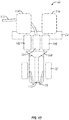
- Figure 13 shows but one possible application of reducing of the seed meter 60 by integrating the drive motor and/or fan of the air seed meters.
- a row unit 40 is provided, which allows for multiple hybrid planting.
- the row unit 40 includes first, second, and third seed meters 102, 104, 106 which are positioned on a single row unit 40 and attached to a frame 24.
- the reduction of width of the seed meters will allow multiple seed meters to be positioned on a row unit 40, while not increasing the width of the row unit 40 more than what is now included. This will allow existing planters to be retrofit with the reduced width seed meters as well.
- the row unit 40 includes a first, second and third seed supply 112, 114 and 116, which supplies different hybrids of seed to each of the seed meters 102, 104, 106.
- some seed supplies may be hoppers positioned at the row unit 40 while other seed supplies may be air seed delivery systems, in which the hybrid is transported from a central or bulk hopper to each of the row units 40.
- the present invention is not to be limited to the configuration shown in Figure 13 , and includes generally any possible configuration of seed supplies. Different numbers of seed supply and seed meters may also be used, including, but not limited to, 2, 3, 4, 5, or more units. Examples of row units including a plurality of seed meters are found in U.S. Application No. 14/478,222 .
- a control system including an intelligent control or operator control can activate to supply the current to the meter, which will begin rotation of the seed disc 64 within the meter housing. This will pass the disc through a seed pool, and will transfer the seed through a seed funnel 108 and down a seed tube 110 to a furrow in the field, which is then closed by the closing wheels 56.
- the current is altered to shut off the seed meter 104 and to activate a different meter instantaneous, such as meter 102.
- the control of the electric motors via electric currents allows for instantaneous and continuously updating change of hybrids to be planted using the system shown in the row unit 40 of Figure 13 .
- the reduction of width will allow the seed meters to be positioned on a generally standard row unit 40.
- the fan can be shut off or left on when the seed meter is not in use. The fan will be able to maintain a pressure differential, even when the meter is not in use, such that seed is maintained at the seed cells. This aids in the reactivation of the meter so that the seed can dispensed almost instantaneously when the meter is activated.
- the present invention has been shown and described in exemplary embodiments to provide a unique and novel planting system in which a motor is integrated with a seed disc for providing direct driving of the seed disc in a seed meter. While it has been stated that the interior stator is fixed and the rotor rotated about it, it is contemplated in some embodiments that the opposite be true, and the outer rotor member be fixed while the inner stator member be rotatable to drive a seed disc. Furthermore, as has been mentioned, the inclusion of the motor integrated with the disc can allow the seed disc motor to be modular. For example, the invention provides a system in which it is capable of switching out the seed cell profiles to fit the need and desire for the seed to be planted using the same seed meter and motor.
- one central or inner stator can be used to power two separate seed discs integrated and operable connected to said stator.
- one single fan assembly can be positioned between the two discs driven by the common stator to power one or the other such as providing the pressure differential for one or the other.
- the invention includes the possibility of a self-contained battery power pack within the seed meter or operably connected to the seed meter such that the seed meters do not need to be run based upon the power supplied by the tractor.
- the seed meters can be wholly independent of one another and can be completely self-contained such that they operate themselves based upon a control system which is connected to each of the meters.
- the seed meters include the use of a sensor to determine a seed that has been attached to a disc.
- a sensor can be positioned within or adjacent the seed meter housing to determine if a seed is engaged with a seed cell of the seed disc.
- Such a sensor could take the form of a laser, smart vision, color vision, or the like.
- the seed be coated with a material to allow the sensor to indicate whether a seed is attached to the seed disc at a seed cell or not.
- the type of motor integrated with the seed disc 64 may be varied to still obtain the benefits, advantages, and objects of the invention.
- an axial flux motor may be used instead of a brushed or brushless DC motor.
- Such a motor may be a type of brushless AC motor.
- a brushless AC electric motor is an electric motor driven by an AC electrical input, which lacks any form of commutator or slip ring.
- the term 'brushless AC motor' will refer to a permanent-magnet synchronous motor (PMSM) or permanent-magnet motor (PMM), a synchronous motor which uses permanent magnets rather than windings in the rotor.
- PMSMs are either axial flux, radial flux, transverse flux, or flux switching depending on the arrangement of components, with each topology having different tradeoffs among efficiency, size, weight, and operating speed.
- Alternative designs may use reluctance rather than magnets.
- Asynchronous induction motors are also brushless AC motors.
- the axial flux permanent magnet (PM) motor generally includes a pancake shape, compact construction, and high power density.
- Axial flux PM motors are also called disk-type motors and can be designed as double-sided or single-sided machines, with or without armature slots, with internal or external PM motors and with surface mounted or interior type PMs. As the output power of the axial flux motor increases, the contact surface between the rotor and the shaft becomes smaller.
- the axial flux motor would take the place of the integrated motor, such as that shown in Figure 4 , which would then power the rotation of the seed disc 62 in the seed meter. It should also be appreciated that other types of relatively thin motors may be used instead of those explicitly mentioned to provide for rotation of the seed disc in the meter.
- a planting implement which includes a seed meter including a seed disc that is integrated with a motor for driving the seed disc within the seed meter.
- the present invention contemplates numerous variations, options, and alternatives, and is not to be limited to the specific exemplary embodiments described herein. For example, while many embodiments and aspects of the embodiments have heretofore been disclosed, it is contemplated that there may be numerous changes to the exemplary embodiments shown. Those skilled in the art will appreciate the various other changes may be included and still within the scope of the invention, as defined by the claims.
Landscapes
- Life Sciences & Earth Sciences (AREA)
- Soil Sciences (AREA)
- Environmental Sciences (AREA)
- Fertilizing (AREA)
- Sowing (AREA)
- Pretreatment Of Seeds And Plants (AREA)
Claims (10)
- Saatgutscheibe (64), umfassend:einen Motor (66) mit einem im Wesentlichen unbeweglichen inneren Element (68) und einem drehbaren äußeren Element (70) undein im Wesentlichen kreisförmiges Element (72), das funktionell am Motor (66) angebracht ist, so dass die Drehung des äußeren Elements (70) das kreisförmige Element (72) dreht, dadurch gekennzeichnet, dass das kreisförmige Element (72), das äußere Element (70) und das innere Element (68) zueinander koaxial sind.
- Saatgutscheibe nach Anspruch 1, wobei das kreisförmige Element (72) einen Saatgutpfad (76) umfasst, umfassend mehrere von einer Achse des kreisförmigen Elements (72) radial beabstandete Saatgutzellen (74).
- Saatgutscheibe nach Anspruch 1, wobei das kreisförmige Element (72) wenigstens teilweise um das drehbare äußere Element (70) des Motors (66) positioniert und damit verbunden ist.
- Saatgutscheibe nach Anspruch 3, wobei der Motor (66) wenigstens ein Anbringungselement (78, 80) zum selektiven Anbringen des Motors (66) am kreisförmigen Element (72) umfasst.
- Saatgutscheibe nach Anspruch 1, wobei das drehbare äußere Element (70) des Motors (66) wenigstens teilweise um einen Teil des kreisförmigen Elements (72) positioniert und damit verbunden ist.
- Saatgutscheibe nach Anspruch 1, ferner umfassend eine Saatgutdosiereinrichtung (60), umfassend:ein Saatgutdosiereinrichtungsgehäuse (62); undwobei die Saatgutscheibe (64) innerhalb des Gehäuses (62) positioniert ist.
- Saatgutscheibe nach Anspruch 6, ferner umfassend ein Gebläse, das funktionell mit dem Gehäuse (62) verbunden ist, so dass das Gebläse an einem Teil entgegengesetzter Seiten der Saatgutzellen (74) des kreisförmigen Elements (72) einen Druckunterschied bereitstellt.
- Saatgutscheibe nach Anspruch 7, wobei das Gebläse an den Saatgutzellen (74) einen Unterdruck erzeugt, so dass ein Saatkorn in dem Saatgutdosiereinrichtungsgehäuse (62) aufgrund des Unterdrucks zeitweilig an der Saatgutscheibe (64) angelagert wird.
- Saatgutscheibe nach Anspruch 1, wobei der Motor (66) wenigstens teilweise innerhalb des Durchmessers des kreisförmigen Elements (72) positioniert ist.
- Saatgutscheibe nach Anspruch 1, wobei wenigstens ein Teil des drehbaren äußeren Elements (70) des Motors (60) einen Durchmesser hat, der größer als der des kreisförmigen Elements (72) ist.
Applications Claiming Priority (2)
| Application Number | Priority Date | Filing Date | Title |
|---|---|---|---|
| US201461925518P | 2014-01-09 | 2014-01-09 | |
| PCT/US2015/010784 WO2015106079A1 (en) | 2014-01-09 | 2015-01-09 | Seed disc with integrated drive |
Publications (3)
| Publication Number | Publication Date |
|---|---|
| EP3091827A1 EP3091827A1 (de) | 2016-11-16 |
| EP3091827A4 EP3091827A4 (de) | 2017-08-09 |
| EP3091827B1 true EP3091827B1 (de) | 2018-10-10 |
Family
ID=53494248
Family Applications (1)
| Application Number | Title | Priority Date | Filing Date |
|---|---|---|---|
| EP15734867.3A Not-in-force EP3091827B1 (de) | 2014-01-09 | 2015-01-09 | Saatscheibe mit integriertem antrieb |
Country Status (8)
| Country | Link |
|---|---|
| US (1) | US9474201B2 (de) |
| EP (1) | EP3091827B1 (de) |
| AR (1) | AR099073A1 (de) |
| BR (1) | BR112016023501A2 (de) |
| CA (1) | CA2936363C (de) |
| RU (1) | RU2668671C2 (de) |
| UA (1) | UA118975C2 (de) |
| WO (1) | WO2015106079A1 (de) |
Families Citing this family (21)
| Publication number | Priority date | Publication date | Assignee | Title |
|---|---|---|---|---|
| US9578799B2 (en) * | 2013-09-30 | 2017-02-28 | Precision Planting Llc | Seed meter unloading systems, methods, and apparatus |
| EP3108731B8 (de) * | 2015-06-22 | 2019-01-23 | S.A. Plantium | Direktantriebs-saatgutvereinzelungsvorrichtung |
| US9661805B1 (en) | 2015-12-29 | 2017-05-30 | Ball Horticultural Company | Seed sowing system and method of use |
| WO2018013858A1 (en) | 2016-07-14 | 2018-01-18 | Precision Planting Llc | Systems, implements, and methods for seed orientation with adjustable singulators during planting |
| CN106797735B (zh) * | 2017-01-24 | 2023-03-28 | 新疆钵施然智能农机股份有限公司 | 一种可调株距的播种器芯盘 |
| IT201700063111A1 (it) * | 2017-06-08 | 2018-12-08 | Matermacc S P A | Dispositivo distributore di materiale per macchine agricole |
| US10257974B1 (en) | 2017-09-22 | 2019-04-16 | Cnh Industrial America Llc | Seed meter with multiple sensors for seed cell status monitoring |
| DE202018006502U1 (de) * | 2017-11-10 | 2020-10-28 | Maschio Gaspardo S.P.A. | Säelement für landwirtschaftliche Präzisions-Sämaschinen und für eine Sämaschine mit einem Element dieser Art |
| US11071243B2 (en) | 2017-12-01 | 2021-07-27 | K And K Farm Implements, Llc | Universal planting drill |
| US10709054B2 (en) | 2018-01-18 | 2020-07-14 | Deere & Company | Pressure supply system for commodity meter of work vehicle |
| US10980167B2 (en) | 2018-06-26 | 2021-04-20 | Cnh Industrial America Llc | Individual row vacuum system |
| CN109838544B (zh) * | 2019-03-08 | 2024-05-10 | 北京农业智能装备技术研究中心 | 后装电机驱动机构与排种器的安装总成 |
| WO2020181345A1 (pt) * | 2019-03-13 | 2020-09-17 | Assy Jose Roberto Do Amaral | Dosador pneumático de sementes de soja |
| DE102021129345A1 (de) * | 2020-11-17 | 2022-05-19 | Cifarelli S.P.A. | Tragbares landwirtschaftsgerät mit axial-/linearmotor |
| CA3203416A1 (en) * | 2020-12-30 | 2022-07-07 | Joseph D. Bassett | Seed meter with vacuum producing device and controlled outlet pressure |
| SE547729C2 (sv) * | 2021-02-23 | 2025-11-18 | Vaederstad Holding Ab | Singuleringsanordning, lantbruksredskap och förfarande för fördelning av granulärt material till mark |
| CN114342607A (zh) * | 2022-01-21 | 2022-04-15 | 王少平 | 一种智慧农业播种机械 |
| CN114568074B (zh) * | 2022-03-22 | 2023-01-17 | 灌云县四队镇农业技术推广服务站 | 一种自由间距玉米种子种植机 |
| WO2025019247A1 (en) | 2023-07-14 | 2025-01-23 | Kinze Manufacturing, Inc. | Agricultural planting implement with telescoping and steerable toolbars and/or row units |
| CN117322202A (zh) * | 2023-11-20 | 2024-01-02 | 辽宁省农业科学院 | 一种气力式电驱动排种器 |
| WO2025126236A1 (en) * | 2023-12-14 | 2025-06-19 | Krishigati Private Limited | A system and method for granular matter drill |
Family Cites Families (10)
| Publication number | Priority date | Publication date | Assignee | Title |
|---|---|---|---|---|
| CH654455A5 (de) * | 1980-05-10 | 1986-02-14 | Papst Motoren Gmbh & Co Kg | Buerstenlose gleichstrommotoranordnung, insbesondere fuer magnetplattenantriebe. |
| AU2003904353A0 (en) * | 2003-08-05 | 2003-08-28 | Holly, John | Seed distribution method and apparatus |
| RU53837U1 (ru) * | 2005-03-01 | 2006-06-10 | Федеральное государственное образовательное учреждение высшего профессионального образования "Тюменская государственная сельскохозяйственная академия" | Ручная сеялка для посева овощных культур |
| US7617785B2 (en) * | 2007-06-27 | 2009-11-17 | Cnh America Llc | Direct drive electric seed metering system |
| US8375873B2 (en) * | 2009-06-02 | 2013-02-19 | Great Plains Manufacturing, Inc. | Seed metering device for agricultural seeder |
| US8281725B2 (en) * | 2009-11-24 | 2012-10-09 | Cnh America Llc | Directly driven seed meter hub drive |
| IT1402950B1 (it) | 2010-11-12 | 2013-09-27 | Maschio Gaspardo Spa | Elemento distributore del seme per seminatrici di precisione, seminatrice includente detto elemento |
| IT1404486B1 (it) | 2011-02-10 | 2013-11-22 | Matermacc S P A | Macchina seminatrice semovente di piccole dimensioni |
| SE535698C2 (sv) * | 2011-03-09 | 2012-11-13 | Vaederstad Verken Ab | Tätningslist och såhus för en såmaskin, samt såmaskin innefattande sådant såhus |
| US9155241B2 (en) * | 2011-04-15 | 2015-10-13 | Agco Corporation | Integral seed meter drive motor |
-
2015
- 2015-01-09 US US14/592,965 patent/US9474201B2/en not_active Expired - Fee Related
- 2015-01-09 EP EP15734867.3A patent/EP3091827B1/de not_active Not-in-force
- 2015-01-09 CA CA2936363A patent/CA2936363C/en not_active Expired - Fee Related
- 2015-01-09 BR BR112016023501A patent/BR112016023501A2/pt active Search and Examination
- 2015-01-09 WO PCT/US2015/010784 patent/WO2015106079A1/en not_active Ceased
- 2015-01-09 AR ARP150100068A patent/AR099073A1/es unknown
- 2015-01-09 RU RU2016132571A patent/RU2668671C2/ru not_active IP Right Cessation
- 2015-09-01 UA UAA201608630A patent/UA118975C2/uk unknown
Non-Patent Citations (1)
| Title |
|---|
| None * |
Also Published As
| Publication number | Publication date |
|---|---|
| AR099073A1 (es) | 2016-06-29 |
| CA2936363C (en) | 2018-07-17 |
| BR112016023501A2 (pt) | 2017-08-15 |
| US20150189826A1 (en) | 2015-07-09 |
| UA118975C2 (uk) | 2019-04-10 |
| RU2016132571A (ru) | 2018-02-14 |
| US9474201B2 (en) | 2016-10-25 |
| RU2668671C2 (ru) | 2018-10-02 |
| EP3091827A4 (de) | 2017-08-09 |
| EP3091827A1 (de) | 2016-11-16 |
| CA2936363A1 (en) | 2015-07-16 |
| WO2015106079A1 (en) | 2015-07-16 |
Similar Documents
| Publication | Publication Date | Title |
|---|---|---|
| US9474201B2 (en) | Seed disc with integrated drive | |
| EP2696667B1 (de) | Integrierter antriebsmotor für ein saatgutmessgerät | |
| US12268119B2 (en) | Agricultural metering system having multiple meter rollers | |
| EP2911499B1 (de) | Pneumatische saatgutvereinzelungsvorrichtung mit innenantrieb | |
| US20120325132A1 (en) | Seed Planter Incorporating Directly Driven Seed Meter Hub Drive | |
| US10823180B2 (en) | Drive system for an agricultural product distribution system | |
| CZ299618B6 (cs) | Dávkovací systém | |
| CA2885140C (en) | Agricultural air cart with product flow control | |
| CN110393062A (zh) | 一种小型电动遥控式水稻直播机 |
Legal Events
| Date | Code | Title | Description |
|---|---|---|---|
| PUAI | Public reference made under article 153(3) epc to a published international application that has entered the european phase |
Free format text: ORIGINAL CODE: 0009012 |
|
| 17P | Request for examination filed |
Effective date: 20160805 |
|
| AK | Designated contracting states |
Kind code of ref document: A1 Designated state(s): AL AT BE BG CH CY CZ DE DK EE ES FI FR GB GR HR HU IE IS IT LI LT LU LV MC MK MT NL NO PL PT RO RS SE SI SK SM TR |
|
| AX | Request for extension of the european patent |
Extension state: BA ME |
|
| DAX | Request for extension of the european patent (deleted) | ||
| A4 | Supplementary search report drawn up and despatched |
Effective date: 20170711 |
|
| RIC1 | Information provided on ipc code assigned before grant |
Ipc: A01C 7/04 20060101ALI20170706BHEP Ipc: A01C 19/02 20060101AFI20170706BHEP |
|
| RIC1 | Information provided on ipc code assigned before grant |
Ipc: A01C 7/04 20060101ALI20180319BHEP Ipc: A01C 19/02 20060101AFI20180319BHEP |
|
| GRAP | Despatch of communication of intention to grant a patent |
Free format text: ORIGINAL CODE: EPIDOSNIGR1 |
|
| STAA | Information on the status of an ep patent application or granted ep patent |
Free format text: STATUS: GRANT OF PATENT IS INTENDED |
|
| INTG | Intention to grant announced |
Effective date: 20180504 |
|
| GRAS | Grant fee paid |
Free format text: ORIGINAL CODE: EPIDOSNIGR3 |
|
| GRAA | (expected) grant |
Free format text: ORIGINAL CODE: 0009210 |
|
| STAA | Information on the status of an ep patent application or granted ep patent |
Free format text: STATUS: THE PATENT HAS BEEN GRANTED |
|
| AK | Designated contracting states |
Kind code of ref document: B1 Designated state(s): AL AT BE BG CH CY CZ DE DK EE ES FI FR GB GR HR HU IE IS IT LI LT LU LV MC MK MT NL NO PL PT RO RS SE SI SK SM TR |
|
| REG | Reference to a national code |
Ref country code: GB Ref legal event code: FG4D |
|
| REG | Reference to a national code |
Ref country code: CH Ref legal event code: EP Ref country code: AT Ref legal event code: REF Ref document number: 1050128 Country of ref document: AT Kind code of ref document: T Effective date: 20181015 |
|
| REG | Reference to a national code |
Ref country code: IE Ref legal event code: FG4D |
|
| REG | Reference to a national code |
Ref country code: DE Ref legal event code: R096 Ref document number: 602015017877 Country of ref document: DE |
|
| REG | Reference to a national code |
Ref country code: SE Ref legal event code: TRGR |
|
| REG | Reference to a national code |
Ref country code: NO Ref legal event code: T2 Effective date: 20181010 |
|
| REG | Reference to a national code |
Ref country code: NL Ref legal event code: MP Effective date: 20181010 |
|
| REG | Reference to a national code |
Ref country code: LT Ref legal event code: MG4D |
|
| REG | Reference to a national code |
Ref country code: AT Ref legal event code: MK05 Ref document number: 1050128 Country of ref document: AT Kind code of ref document: T Effective date: 20181010 |
|
| PG25 | Lapsed in a contracting state [announced via postgrant information from national office to epo] |
Ref country code: NL Free format text: LAPSE BECAUSE OF FAILURE TO SUBMIT A TRANSLATION OF THE DESCRIPTION OR TO PAY THE FEE WITHIN THE PRESCRIBED TIME-LIMIT Effective date: 20181010 |
|
| PG25 | Lapsed in a contracting state [announced via postgrant information from national office to epo] |
Ref country code: LV Free format text: LAPSE BECAUSE OF FAILURE TO SUBMIT A TRANSLATION OF THE DESCRIPTION OR TO PAY THE FEE WITHIN THE PRESCRIBED TIME-LIMIT Effective date: 20181010 Ref country code: AT Free format text: LAPSE BECAUSE OF FAILURE TO SUBMIT A TRANSLATION OF THE DESCRIPTION OR TO PAY THE FEE WITHIN THE PRESCRIBED TIME-LIMIT Effective date: 20181010 Ref country code: FI Free format text: LAPSE BECAUSE OF FAILURE TO SUBMIT A TRANSLATION OF THE DESCRIPTION OR TO PAY THE FEE WITHIN THE PRESCRIBED TIME-LIMIT Effective date: 20181010 Ref country code: BG Free format text: LAPSE BECAUSE OF FAILURE TO SUBMIT A TRANSLATION OF THE DESCRIPTION OR TO PAY THE FEE WITHIN THE PRESCRIBED TIME-LIMIT Effective date: 20190110 Ref country code: PL Free format text: LAPSE BECAUSE OF FAILURE TO SUBMIT A TRANSLATION OF THE DESCRIPTION OR TO PAY THE FEE WITHIN THE PRESCRIBED TIME-LIMIT Effective date: 20181010 Ref country code: HR Free format text: LAPSE BECAUSE OF FAILURE TO SUBMIT A TRANSLATION OF THE DESCRIPTION OR TO PAY THE FEE WITHIN THE PRESCRIBED TIME-LIMIT Effective date: 20181010 Ref country code: IS Free format text: LAPSE BECAUSE OF FAILURE TO SUBMIT A TRANSLATION OF THE DESCRIPTION OR TO PAY THE FEE WITHIN THE PRESCRIBED TIME-LIMIT Effective date: 20190210 Ref country code: ES Free format text: LAPSE BECAUSE OF FAILURE TO SUBMIT A TRANSLATION OF THE DESCRIPTION OR TO PAY THE FEE WITHIN THE PRESCRIBED TIME-LIMIT Effective date: 20181010 Ref country code: LT Free format text: LAPSE BECAUSE OF FAILURE TO SUBMIT A TRANSLATION OF THE DESCRIPTION OR TO PAY THE FEE WITHIN THE PRESCRIBED TIME-LIMIT Effective date: 20181010 |
|
| PGFP | Annual fee paid to national office [announced via postgrant information from national office to epo] |
Ref country code: NO Payment date: 20190109 Year of fee payment: 5 Ref country code: DE Payment date: 20190102 Year of fee payment: 5 Ref country code: FR Payment date: 20190111 Year of fee payment: 5 Ref country code: IT Payment date: 20190121 Year of fee payment: 5 |
|
| PG25 | Lapsed in a contracting state [announced via postgrant information from national office to epo] |
Ref country code: GR Free format text: LAPSE BECAUSE OF FAILURE TO SUBMIT A TRANSLATION OF THE DESCRIPTION OR TO PAY THE FEE WITHIN THE PRESCRIBED TIME-LIMIT Effective date: 20190111 Ref country code: PT Free format text: LAPSE BECAUSE OF FAILURE TO SUBMIT A TRANSLATION OF THE DESCRIPTION OR TO PAY THE FEE WITHIN THE PRESCRIBED TIME-LIMIT Effective date: 20190210 Ref country code: AL Free format text: LAPSE BECAUSE OF FAILURE TO SUBMIT A TRANSLATION OF THE DESCRIPTION OR TO PAY THE FEE WITHIN THE PRESCRIBED TIME-LIMIT Effective date: 20181010 Ref country code: RS Free format text: LAPSE BECAUSE OF FAILURE TO SUBMIT A TRANSLATION OF THE DESCRIPTION OR TO PAY THE FEE WITHIN THE PRESCRIBED TIME-LIMIT Effective date: 20181010 |
|
| PGFP | Annual fee paid to national office [announced via postgrant information from national office to epo] |
Ref country code: SE Payment date: 20190110 Year of fee payment: 5 |
|
| REG | Reference to a national code |
Ref country code: DE Ref legal event code: R097 Ref document number: 602015017877 Country of ref document: DE |
|
| PG25 | Lapsed in a contracting state [announced via postgrant information from national office to epo] |
Ref country code: CZ Free format text: LAPSE BECAUSE OF FAILURE TO SUBMIT A TRANSLATION OF THE DESCRIPTION OR TO PAY THE FEE WITHIN THE PRESCRIBED TIME-LIMIT Effective date: 20181010 Ref country code: DK Free format text: LAPSE BECAUSE OF FAILURE TO SUBMIT A TRANSLATION OF THE DESCRIPTION OR TO PAY THE FEE WITHIN THE PRESCRIBED TIME-LIMIT Effective date: 20181010 |
|
| PLBE | No opposition filed within time limit |
Free format text: ORIGINAL CODE: 0009261 |
|
| STAA | Information on the status of an ep patent application or granted ep patent |
Free format text: STATUS: NO OPPOSITION FILED WITHIN TIME LIMIT |
|
| PG25 | Lapsed in a contracting state [announced via postgrant information from national office to epo] |
Ref country code: RO Free format text: LAPSE BECAUSE OF FAILURE TO SUBMIT A TRANSLATION OF THE DESCRIPTION OR TO PAY THE FEE WITHIN THE PRESCRIBED TIME-LIMIT Effective date: 20181010 Ref country code: SK Free format text: LAPSE BECAUSE OF FAILURE TO SUBMIT A TRANSLATION OF THE DESCRIPTION OR TO PAY THE FEE WITHIN THE PRESCRIBED TIME-LIMIT Effective date: 20181010 Ref country code: EE Free format text: LAPSE BECAUSE OF FAILURE TO SUBMIT A TRANSLATION OF THE DESCRIPTION OR TO PAY THE FEE WITHIN THE PRESCRIBED TIME-LIMIT Effective date: 20181010 Ref country code: SM Free format text: LAPSE BECAUSE OF FAILURE TO SUBMIT A TRANSLATION OF THE DESCRIPTION OR TO PAY THE FEE WITHIN THE PRESCRIBED TIME-LIMIT Effective date: 20181010 Ref country code: MC Free format text: LAPSE BECAUSE OF FAILURE TO SUBMIT A TRANSLATION OF THE DESCRIPTION OR TO PAY THE FEE WITHIN THE PRESCRIBED TIME-LIMIT Effective date: 20181010 |
|
| REG | Reference to a national code |
Ref country code: CH Ref legal event code: PL |
|
| 26N | No opposition filed |
Effective date: 20190711 |
|
| GBPC | Gb: european patent ceased through non-payment of renewal fee |
Effective date: 20190110 |
|
| PG25 | Lapsed in a contracting state [announced via postgrant information from national office to epo] |
Ref country code: LU Free format text: LAPSE BECAUSE OF NON-PAYMENT OF DUE FEES Effective date: 20190109 |
|
| REG | Reference to a national code |
Ref country code: BE Ref legal event code: MM Effective date: 20190131 |
|
| REG | Reference to a national code |
Ref country code: IE Ref legal event code: MM4A |
|
| PG25 | Lapsed in a contracting state [announced via postgrant information from national office to epo] |
Ref country code: SI Free format text: LAPSE BECAUSE OF FAILURE TO SUBMIT A TRANSLATION OF THE DESCRIPTION OR TO PAY THE FEE WITHIN THE PRESCRIBED TIME-LIMIT Effective date: 20181010 |
|
| PG25 | Lapsed in a contracting state [announced via postgrant information from national office to epo] |
Ref country code: BE Free format text: LAPSE BECAUSE OF NON-PAYMENT OF DUE FEES Effective date: 20190131 |
|
| PG25 | Lapsed in a contracting state [announced via postgrant information from national office to epo] |
Ref country code: CH Free format text: LAPSE BECAUSE OF NON-PAYMENT OF DUE FEES Effective date: 20190131 Ref country code: LI Free format text: LAPSE BECAUSE OF NON-PAYMENT OF DUE FEES Effective date: 20190131 Ref country code: GB Free format text: LAPSE BECAUSE OF NON-PAYMENT OF DUE FEES Effective date: 20190110 |
|
| PG25 | Lapsed in a contracting state [announced via postgrant information from national office to epo] |
Ref country code: IE Free format text: LAPSE BECAUSE OF NON-PAYMENT OF DUE FEES Effective date: 20190109 |
|
| PG25 | Lapsed in a contracting state [announced via postgrant information from national office to epo] |
Ref country code: TR Free format text: LAPSE BECAUSE OF FAILURE TO SUBMIT A TRANSLATION OF THE DESCRIPTION OR TO PAY THE FEE WITHIN THE PRESCRIBED TIME-LIMIT Effective date: 20181010 |
|
| PG25 | Lapsed in a contracting state [announced via postgrant information from national office to epo] |
Ref country code: MT Free format text: LAPSE BECAUSE OF NON-PAYMENT OF DUE FEES Effective date: 20190109 |
|
| REG | Reference to a national code |
Ref country code: DE Ref legal event code: R119 Ref document number: 602015017877 Country of ref document: DE |
|
| REG | Reference to a national code |
Ref country code: NO Ref legal event code: MMEP |
|
| REG | Reference to a national code |
Ref country code: SE Ref legal event code: EUG |
|
| REG | Reference to a national code |
Ref country code: SE Ref legal event code: EUG |
|
| PG25 | Lapsed in a contracting state [announced via postgrant information from national office to epo] |
Ref country code: SE Free format text: LAPSE BECAUSE OF NON-PAYMENT OF DUE FEES Effective date: 20200110 Ref country code: DE Free format text: LAPSE BECAUSE OF NON-PAYMENT OF DUE FEES Effective date: 20200801 Ref country code: NO Free format text: LAPSE BECAUSE OF NON-PAYMENT OF DUE FEES Effective date: 20200131 Ref country code: FR Free format text: LAPSE BECAUSE OF NON-PAYMENT OF DUE FEES Effective date: 20200131 |
|
| PG25 | Lapsed in a contracting state [announced via postgrant information from national office to epo] |
Ref country code: IT Free format text: LAPSE BECAUSE OF NON-PAYMENT OF DUE FEES Effective date: 20200109 |
|
| PG25 | Lapsed in a contracting state [announced via postgrant information from national office to epo] |
Ref country code: CY Free format text: LAPSE BECAUSE OF FAILURE TO SUBMIT A TRANSLATION OF THE DESCRIPTION OR TO PAY THE FEE WITHIN THE PRESCRIBED TIME-LIMIT Effective date: 20181010 |
|
| PG25 | Lapsed in a contracting state [announced via postgrant information from national office to epo] |
Ref country code: HU Free format text: LAPSE BECAUSE OF FAILURE TO SUBMIT A TRANSLATION OF THE DESCRIPTION OR TO PAY THE FEE WITHIN THE PRESCRIBED TIME-LIMIT; INVALID AB INITIO Effective date: 20150109 |
|
| PG25 | Lapsed in a contracting state [announced via postgrant information from national office to epo] |
Ref country code: MK Free format text: LAPSE BECAUSE OF FAILURE TO SUBMIT A TRANSLATION OF THE DESCRIPTION OR TO PAY THE FEE WITHIN THE PRESCRIBED TIME-LIMIT Effective date: 20181010 |