EP3091643B1 - Drive wheel set, wire storage frame, guide wheel frame, traction mechanism and conveying mechanism - Google Patents
Drive wheel set, wire storage frame, guide wheel frame, traction mechanism and conveying mechanism Download PDFInfo
- Publication number
- EP3091643B1 EP3091643B1 EP13900747.0A EP13900747A EP3091643B1 EP 3091643 B1 EP3091643 B1 EP 3091643B1 EP 13900747 A EP13900747 A EP 13900747A EP 3091643 B1 EP3091643 B1 EP 3091643B1
- Authority
- EP
- European Patent Office
- Prior art keywords
- wheel set
- external rotor
- traction
- wire
- fixing
- Prior art date
- Legal status (The legal status is an assumption and is not a legal conclusion. Google has not performed a legal analysis and makes no representation as to the accuracy of the status listed.)
- Active
Links
Images



Classifications
-
- B—PERFORMING OPERATIONS; TRANSPORTING
- B65—CONVEYING; PACKING; STORING; HANDLING THIN OR FILAMENTARY MATERIAL
- B65H—HANDLING THIN OR FILAMENTARY MATERIAL, e.g. SHEETS, WEBS, CABLES
- B65H51/00—Forwarding filamentary material
- B65H51/32—Supporting or driving arrangements for forwarding devices
-
- B—PERFORMING OPERATIONS; TRANSPORTING
- B65—CONVEYING; PACKING; STORING; HANDLING THIN OR FILAMENTARY MATERIAL
- B65G—TRANSPORT OR STORAGE DEVICES, e.g. CONVEYORS FOR LOADING OR TIPPING, SHOP CONVEYOR SYSTEMS OR PNEUMATIC TUBE CONVEYORS
- B65G15/00—Conveyors having endless load-conveying surfaces, i.e. belts and like continuous members, to which tractive effort is transmitted by means other than endless driving elements of similar configuration
- B65G15/30—Belts or like endless load-carriers
- B65G15/50—Endless load-carriers consisting of a series of parallel ropes or belt strips
-
- B—PERFORMING OPERATIONS; TRANSPORTING
- B65—CONVEYING; PACKING; STORING; HANDLING THIN OR FILAMENTARY MATERIAL
- B65G—TRANSPORT OR STORAGE DEVICES, e.g. CONVEYORS FOR LOADING OR TIPPING, SHOP CONVEYOR SYSTEMS OR PNEUMATIC TUBE CONVEYORS
- B65G23/00—Driving gear for endless conveyors; Belt- or chain-tensioning arrangements
- B65G23/02—Belt- or chain-engaging elements
- B65G23/04—Drums, rollers, or wheels
- B65G23/08—Drums, rollers, or wheels with self-contained driving mechanisms, e.g. motors and associated gearing
-
- B—PERFORMING OPERATIONS; TRANSPORTING
- B65—CONVEYING; PACKING; STORING; HANDLING THIN OR FILAMENTARY MATERIAL
- B65H—HANDLING THIN OR FILAMENTARY MATERIAL, e.g. SHEETS, WEBS, CABLES
- B65H51/00—Forwarding filamentary material
- B65H51/02—Rotary devices, e.g. with helical forwarding surfaces
- B65H51/04—Rollers, pulleys, capstans, or intermeshing rotary elements
- B65H51/06—Rollers, pulleys, capstans, or intermeshing rotary elements arranged to operate singly
-
- B—PERFORMING OPERATIONS; TRANSPORTING
- B65—CONVEYING; PACKING; STORING; HANDLING THIN OR FILAMENTARY MATERIAL
- B65H—HANDLING THIN OR FILAMENTARY MATERIAL, e.g. SHEETS, WEBS, CABLES
- B65H51/00—Forwarding filamentary material
- B65H51/02—Rotary devices, e.g. with helical forwarding surfaces
- B65H51/04—Rollers, pulleys, capstans, or intermeshing rotary elements
- B65H51/08—Rollers, pulleys, capstans, or intermeshing rotary elements arranged to operate in groups or in co-operation with other elements
-
- B—PERFORMING OPERATIONS; TRANSPORTING
- B65—CONVEYING; PACKING; STORING; HANDLING THIN OR FILAMENTARY MATERIAL
- B65H—HANDLING THIN OR FILAMENTARY MATERIAL, e.g. SHEETS, WEBS, CABLES
- B65H51/00—Forwarding filamentary material
- B65H51/02—Rotary devices, e.g. with helical forwarding surfaces
- B65H51/04—Rollers, pulleys, capstans, or intermeshing rotary elements
- B65H51/08—Rollers, pulleys, capstans, or intermeshing rotary elements arranged to operate in groups or in co-operation with other elements
- B65H51/12—Rollers, pulleys, capstans, or intermeshing rotary elements arranged to operate in groups or in co-operation with other elements in spaced relation to provide a series of independent forwarding surfaces around which material is passed or wound
-
- B—PERFORMING OPERATIONS; TRANSPORTING
- B65—CONVEYING; PACKING; STORING; HANDLING THIN OR FILAMENTARY MATERIAL
- B65H—HANDLING THIN OR FILAMENTARY MATERIAL, e.g. SHEETS, WEBS, CABLES
- B65H51/00—Forwarding filamentary material
- B65H51/14—Aprons, endless belts, lattices, or like driven elements
-
- B—PERFORMING OPERATIONS; TRANSPORTING
- B65—CONVEYING; PACKING; STORING; HANDLING THIN OR FILAMENTARY MATERIAL
- B65H—HANDLING THIN OR FILAMENTARY MATERIAL, e.g. SHEETS, WEBS, CABLES
- B65H51/00—Forwarding filamentary material
- B65H51/20—Devices for temporarily storing filamentary material during forwarding, e.g. for buffer storage
-
- B—PERFORMING OPERATIONS; TRANSPORTING
- B65—CONVEYING; PACKING; STORING; HANDLING THIN OR FILAMENTARY MATERIAL
- B65H—HANDLING THIN OR FILAMENTARY MATERIAL, e.g. SHEETS, WEBS, CABLES
- B65H57/00—Guides for filamentary materials; Supports therefor
- B65H57/14—Pulleys, rollers, or rotary bars
-
- H—ELECTRICITY
- H02—GENERATION; CONVERSION OR DISTRIBUTION OF ELECTRIC POWER
- H02K—DYNAMO-ELECTRIC MACHINES
- H02K16/00—Machines with more than one rotor or stator
-
- H—ELECTRICITY
- H02—GENERATION; CONVERSION OR DISTRIBUTION OF ELECTRIC POWER
- H02K—DYNAMO-ELECTRIC MACHINES
- H02K21/00—Synchronous motors having permanent magnets; Synchronous generators having permanent magnets
- H02K21/12—Synchronous motors having permanent magnets; Synchronous generators having permanent magnets with stationary armatures and rotating magnets
- H02K21/22—Synchronous motors having permanent magnets; Synchronous generators having permanent magnets with stationary armatures and rotating magnets with magnets rotating around the armatures, e.g. flywheel magnetos
-
- H—ELECTRICITY
- H02—GENERATION; CONVERSION OR DISTRIBUTION OF ELECTRIC POWER
- H02K—DYNAMO-ELECTRIC MACHINES
- H02K7/00—Arrangements for handling mechanical energy structurally associated with dynamo-electric machines, e.g. structural association with mechanical driving motors or auxiliary dynamo-electric machines
- H02K7/10—Structural association with clutches, brakes, gears, pulleys or mechanical starters
- H02K7/1004—Structural association with clutches, brakes, gears, pulleys or mechanical starters with pulleys
- H02K7/1012—Machine arranged inside the pulley
- H02K7/1016—Machine of the outer rotor type
-
- H—ELECTRICITY
- H02—GENERATION; CONVERSION OR DISTRIBUTION OF ELECTRIC POWER
- H02K—DYNAMO-ELECTRIC MACHINES
- H02K7/00—Arrangements for handling mechanical energy structurally associated with dynamo-electric machines, e.g. structural association with mechanical driving motors or auxiliary dynamo-electric machines
- H02K7/14—Structural association with mechanical loads, e.g. with hand-held machine tools or fans
-
- B—PERFORMING OPERATIONS; TRANSPORTING
- B65—CONVEYING; PACKING; STORING; HANDLING THIN OR FILAMENTARY MATERIAL
- B65H—HANDLING THIN OR FILAMENTARY MATERIAL, e.g. SHEETS, WEBS, CABLES
- B65H2701/00—Handled material; Storage means
- B65H2701/30—Handled filamentary material
- B65H2701/36—Wires
Definitions
- the present application relates to a drive wheel set and a vertical-type wire storage frame, a swing-type wire storage frame, a guide wheel frame, a traction mechanism and a multi-path conveying mechanism having the drive wheel set.
- a plurality of motors are required when a plurality of machine equipment is driven, when the plurality of motors are in the same space especially used in parallel, each motor has a shaft, the plurality of motors have a plurality of shafts, and when the plurality of motors are used at the same time, a phenomenon exists that large space is occupied such that the plurality of motors cannot be placed in parallel. This is because, due to the volume of each motor plus a transmission manner of a belt or gear as well as limitations of the existing space, the motor cannot be placed in many places where an active motor should be modulated, and only driven wheels can be used or some functions of the equipment are lost, which may lead to product quality issues.
- EP2466730A1 disclosed a gearless roller drive.
- the gearless roller drive has a transverse flux motor that is equipped with an internal stator and an outer rotor. Several permanent magnets are circumferentially arranged one behind the other.
- the transverse flux unit and an electric control unit are axially arranged one behind the other. The dimensions of the electric control unit radially along axis of the stator, are not more than the rotor diameter.
- the electrical terminal conductors are connected with the control unit through plug connectors.
- the vertical-type wire storage frame stores wires when a pay-off reel pays off, to be ready for the pay-off reel to change a reel, when the pay-off reel is empty and needs to change the reel, the vertical-type wire storage frame discharges wires, so as to avoid shutdown of production caused by reel changing of the pay-off reel, thus ensuring large-scale continuous production of the cables.
- the vertical-type wire storage frame may also be used in a situation where a wire storage reel changes a reel, that is, the vertical-type wire storage frame discharges wires when the wire storage reel stores wires, and the vertical-type wire storage frame stores wires when the wire storage reel is full and changes the reel.
- a traditional vertical-type wire storage frame includes a fixing portion, a cushion portion, a master wire wheel set, a master pivot, a slave wire wheel set and a slave pivot, the fixing portion is disposed vertically, one end of the master pivot is fixed onto the fixing portion, the cushion portion is fixed onto the fixing portion and located below the master pivot, one end of the slave pivot is fixed onto the cushion portion, the master pivot and the slave pivot are disposed in parallel, the master wire wheel set is installed on the master pivot, and the slave wire wheel set is installed on the slave pivot.
- the cables are wound on wire wheels in the master wire wheel set and the slave wire wheel set, the cables drive at a fixed speed, the cables produce friction forces with master wire wheels and slave wire wheels, and the friction forces drive the master wire wheels and the slave wire wheels to rotate.
- Chinese Patent Publication 102336348A discloses a vertical-type wire storage frame.
- the vertical-type wire storage frame is used to solve the problems of wear-out and cutting of external insulation of the cables; however, the master wire wheel set or the slave wire wheel set of the vertical-type wire storage frame has a problem of occupying a relatively large volume when using a drive speed regulating device in the form of a motor.
- the swing-type wire storage frame stores wires when a pay-off reel pays off, to be ready for the pay-off reel to change a reel, when the pay-off reel is empty and needs to change the reel, the swing-type wire storage frame discharges wires, so as to avoid shutdown of production caused by reel changing of the pay-off reel, thus ensuring large-scale continuous production of the cables.
- the swing-type wire storage frame may also be used in a situation where a wire storage reel changes a reel, that is, the swing-type wire storage frame discharges wires when the wire storage reel stores wires, and the swing-type wire storage frame stores wires when the wire storage reel is full and changes the reel.
- a traditional swing-type wire storage frame includes a fixing frame and a swing frame.
- the fixing frame is horizontally provided with a master wire wheel set.
- the swing frame is pivoted onto the fixing frame and pivoted below the master wire wheel set.
- One end of the swing frame is horizontally provided with a slave wire wheel set.
- the swing-type wire storage frame drives the slave wire wheel set to swing through swing of the swing frame, thus achieving storage or release of wires or tubes, the wires or tubes are wound on wire wheels in the master wire wheel set and the slave wire wheel set, the wires or tubes drive at a fixed speed, the cables produce friction forces with master wire wheels and slave wire wheels, and the friction forces drive the master wire wheels and the slave wire wheels to rotate.
- Chinese Patent Publication 102336348A discloses a wire storage apparatus.
- the wire storage apparatus is used to solve the problems of wear-out and cutting of external insulation of the cables; however, the master wire wheel set or the slave wire wheel set of the wire storage apparatus has a problem of occupying a relatively large volume when using a drive speed regulating device in the form of a motor.
- the guide wheel frame includes a fixing frame and several arms fixed onto the fixing frame. Each arm is fixed with a wire wheel set.
- a guide function of the cables or tubes is achieved through the wire wheel set of the guide wheel frame; as the wire wheel set has several wire wheels, several cables or tubes in the same direction can be guided.
- the wires or tubes are respectively wound on several wire wheels of the wire wheel set to drive at a fixed speed.
- tube wires such as wires, cables or heat-shrinkable tubes
- a traction mechanism to pull the tube wires.
- the current traction mechanism includes two traction wheels oppositely disposed, each of which is driven by an internal rotor motor, has an incompact structure, and occupies great space.
- the current conveying mechanism includes two traction wheels oppositely disposed, each of which is driven by an internal rotor motor, has an incompact structure, and occupies great space.
- An object of the present application is to provide a drive wheel set small in size and occupying less space.
- Another object of the present application is to provide a vertical-type wire storage frame which is small in size, has large wire storage capacity and can ensure wire quality after wire storage.
- Another object of the present application is to provide a swing-type wire storage frame which is small in size, has large wire storage capacity and can ensure wire quality after wire storage.
- Another object of the present application is to provide a guide wire frame which is small in size and can avoid wear-out and cutting of external insulation of cables or tubes wound thereon.
- Another object of the present application is to provide a traction mechanism compact in structure and occupying less space.
- Another object of the present application is to provide a multi-path conveying mechanism compact in structure and occupying less space.
- the present application provides a drive wheel set, including a common shaft and at least two external rotor motors installed on the common shaft, external rotors of the external rotor motors forming drive wheels of the drive wheel set.
- Each of the external rotor motors includes a winding stator and an external rotor, the winding stator is fixed onto the common shaft, and the external rotor is disposed outside the winding stator and pivoted onto the common shaft.
- the external rotors are permanent magnetic external rotors.
- the winding stators of the external rotor motors and the common shaft are respectively provided with key slots and are fixed into the key slots through buckling keys to fix the winding stators onto the common shaft.
- the external rotors of the external rotor motors are pivoted onto the common shaft through bearings.
- the common shaft is provided with a wiring hole extending axially, wherein wire slots are disposed where the common shaft corresponds to the external rotor motors installed thereon, and wire harnesses of the drive wheels enter into the common shaft through the wire slots and are led out through the wiring hole.
- the external rotor motor is further provided with a cover body, the cover body and the external rotor are detachably fixed together, and the cover body is pivoted onto the common shaft through a bearing.
- the external rotor motors are squirrel-cage asynchronous motors.
- the distance between two adjacent external rotor motors can be minimized, which enables the drive wheel set to be small in size, occupy less space, and suitable for a situation where a plurality of motors need to be driven but sufficient space is lacking.
- the present application provides a vertical-type wire storage frame, including a fixing frame and a master wire wheel set and a slave wire wheel set disposed on the fixing frame, the master wire wheel set and the slave wire wheel set being disposed in parallel, wherein at least one of the master wire wheel set and the slave wire wheel set is any drive wheel set described above.
- the master wire wheel set and the slave wire wheel set of the vertical-type wire storage frame of the present application is a drive wheel set
- several external rotor motors of the drive wheel set are disposed on the same common shaft, the distance between two adjacent external rotor motors can be minimized, and the drive wheel set may be very small in size, which causes the vertical-type wire storage frame to be small in size and occupy less space.
- the external rotor motors of the drive wheel set of the vertical-type wire storage frame of the present application are capable of self-driving, the linear speed of the external rotor motors can be equal to the speed of the tubes on the external rotor motors, and no friction force is produced therebetween any more, thus avoiding that the friction between the tubes and the external rotor motors produce wear-out and cutting of external insulation of the tubes and ensuring the quality of the tubes after wire storage.
- the external rotor motors are capable of self-driving, which is no longer provided by a pulling force of the tubes, the pulling force of the tubes decreases; certainly, it is also possible to adjust the external rotor motors as required to make a ratio between the linear speed of the external rotors and the speed of the cables wound on the external rotors decrease the friction force produced by them.
- more external rotor motors can be disposed on the drive wheel set, so as to store more tubes and ensure the quality of the stored tubes.
- the present application provides a swing-type wire storage frame, including a fixing frame and a swing frame, the fixing frame being horizontally provided with a master wire wheel set, the swing frame being pivoted onto the fixing frame and pivoted below the master wire wheel set, and one end of the swing frame being horizontally provided with a slave wire wheel set, wherein at least one of the master wire wheel set and the slave wire wheel set is any drive wheel set described above.
- the swing frame is further provided with a counterweight member
- the counterweight member is located on the other end of the swing frame opposite to the slave wire wheel set
- the counterweight member includes two fixing rods, a counterweight adjusting rod disposed between the two fixing rods and a counterweight portion slidable on the counterweight adjusting rod.
- the master wire wheel set and the slave wire wheel set of the swing-type wire storage frame of the present application is a drive wheel set, several external rotor motors of the drive wheel set are disposed on the same common shaft, the distance between two adjacent external rotor motors can be minimized, and the drive wheel set may be very small in size, which causes the swing-type wire storage frame to be small in size and occupy less space.
- the external rotor motors of the drive wheel set of the swing-type wire storage frame of the present application are capable of self-driving, the linear speed of the external rotor motors can be equal to the speed of the tubes on the external rotor motors, and no friction force is produced therebetween any more, thus avoiding that the friction between the tubes and the external rotor motors produce wear-out and cutting of external insulation of the tubes and ensuring the quality of the tubes after wire storage.
- the external rotor motors are capable of self-driving, which is no longer provided by a pulling force of the tubes, the pulling force of the tubes decreases; certainly, it is also possible to adjust the external rotor motors as required to make a ratio between the linear speed of the external rotors and the speed of the cables wound on the external rotors decrease the friction force produced by them.
- more external rotor motors can be disposed on the drive wheel set, so as to store more tubes and ensure the quality of the stored tubes.
- the present application provides a guide wheel frame, including a fixing frame and at least two arms fixed onto the fixing frame, each of which is fixed with a wire wheel set, wherein at least one of the wire wheel sets is any drive wheel set described above.
- the wire wheel sets of the guide wire frame of the present application is a drive wheel set
- several external rotor motors of the drive wheel set are disposed on the same common shaft, the distance between two adjacent external rotor motors can be minimized, and the drive wheel set may be very small in size, which causes the guide wheel frame to be small in size and occupy less space.
- the external rotor motors of the drive wheel set of the guide wire frame of the present application are capable of self-driving, the linear speed of the external rotor motors can be equal to the speed of the tubes on the external rotor motors, and no friction force is produced therebetween any more, thus avoiding that the friction between the tubes and the external rotor motors produce wear-out and cutting of external insulation of the tubes and ensuring the quality of the tubes after wire storage.
- the external rotor motors are capable of self-driving, which is no longer provided by a pulling force of the tubes, the pulling force of the tubes decreases; certainly, it is also possible to adjust the external rotor motors as required to make a ratio between the linear speed of the external rotors and the speed of the cables wound on the external rotors decrease the friction force produced by them.
- the present application provides a traction mechanism, including a fixing frame and a pair of oppositely disposed traction wheel sets fixed onto the fixing frame, two common shafts of the pair of traction wheel sets being disposed in parallel, and traction wheels in the pair of traction wheel sets being disposed in parallel and correspondingly adjacent to each other, wherein each traction wheel set is any drive wheel set described above, and external rotors of the external rotor motors of the drive wheel set form the traction wheels of the traction wheel sets.
- the two pairs of traction wheel sets are disposed in parallel
- the fixing frame is two pairs of fixing plates disposed up and down in parallel
- common shafts of the two pairs of traction wheel sets are respectively fixed to two ends of the fixing plates
- the traction wheels of one pair of traction wheel sets and the traction wheels of the other pair of traction wheel sets are sleeved with a traction belt.
- the fixing plates are provided with receiving holes and threaded end holes disposed along a front-back direction of the two pairs of traction wheel sets, the receiving holes receive a shaft fixing block that can move back and forth in the receiving holes, the common shaft is fixed onto the shaft fixing block, the threaded end holes are fixed with a threaded adjusting length member by thread, one end of the threaded adjusting length member is fixed to the shaft fixing block, and the other end of the threaded adjusting length member extends out of the threaded end holes.
- upper and lower fixing plates on the same side are respectively fixed with a fixing member, wherein one fixing member is provided with a threaded hole, the threaded hole is provided with a threaded adjusting thickness member, one end of the threaded adjusting thickness member extends out of the threaded hole, and the other end of the threaded adjusting thickness member is connected with another fixing member.
- the upper and lower fixing plates on the same side are respectively fixed with a guide fixing member, wherein one guide fixing member is provided with a guide hole, the guide hole is provided with a guide rod, and the other end of the guide rod is connected with the another guide fixing member.
- the present application provides a multi-path conveying mechanism, including a fixing frame, a pair of oppositely disposed traction wheel sets fixed onto the fixing frame and a plurality of transmission belts, two common shafts of the pair of traction wheel sets being disposed in parallel, wherein a plurality of traction wheels of one traction wheel set and a plurality of traction wheels of the other opposite traction wheel set are respectively sleeved with one of the transmission belts correspondingly, wherein each traction wheel set is any drive wheel set described above, and external rotors of the external rotor motors of the drive wheel set form traction wheels of the traction wheel set.
- the fixing frame is two pairs of fixing plates disposed in parallel, and common shafts of one pair of the fixing plates are correspondingly fixed to two ends of the fixing plates respectively.
- the fixing plates are provided with receiving holes and threaded end holes disposed along a front-back direction of one pair of the traction wheel sets, the receiving holes receive a shaft fixing block that can move back and forth in the receiving holes, the common shaft is fixed onto the shaft fixing block, the threaded end holes are fixed with a threaded adjusting length member by thread, one end of the threaded adjusting length member is fixed to the shaft fixing block, and the other end of the threaded adjusting length member extends out of the threaded end holes.
- a drive wheel set according to an embodiment of the present application includes a common shaft 10 and at least two external rotor motors 20 installed on the common shaft 10.
- the external rotor motors 20 each include a winding stator 21 and an external rotor 22, and the external rotors 22 of the external rotor motors form drive wheels of the drive wheel set.
- the winding stator 21 is fixed onto the common shaft 10, provided thereon with coils.
- the common shaft 10 is provided with a common shaft key slot 11, and the winding stator 21 is provided with a stator key slot 211.
- the common shaft key slot 11 and the stator key slot 211 are internally fixed with a buckling key 30, so as to fix the winding stator 21 onto the common shaft 10.
- the winding stator 21 may also be fixed onto the common shaft 10 through direct welding, and actually, any other manners that can fix the winding stator 21 onto the common shaft 10 are feasible.
- the external rotor 22 has a magnet, which is pivoted onto the common shaft 10 and disposed outside the winding stator 21.
- the external rotor 22 is preferably a permanent magnetic external rotor.
- the external rotor 22 has a bracket 221, and the bracket 221 of the external rotor 22 is pivoted onto the common shaft 10 through a bearing 40.
- the bracket 221 of the external rotor 22 may also be directly pivoted onto the common shaft 10, and any other manners that can pivot the external rotor 22 onto the common shaft 10 directly or indirectly are feasible.
- the external rotor motor 20 is further provided with a cover body 23.
- the cover body 23 and the external rotor 22 are detachably fixed together, and the cover body 23 is pivoted onto the common shaft 10 through the bearing 40.
- the cover body 23 may also be integrally formed with the external rotor motor 20.
- the common shaft 10 is provided with a wiring hole 12 extending axially, wherein wire slots 13 are disposed where the common shaft 10 corresponds to the external rotor motors 20 installed thereon, and wire harnesses 50 of each external rotor motor 20 enter into the common shaft through the wire slots 13 and are led out through the wiring hole 12, which can facilitate wiring and save space.
- the wire harnesses of the external rotor motors 20 may also be led out through gaps between the external rotor motors 20.
- the external rotor motors 20 of the drive wheel set can operate separately, the rotating speed of the external rotor of each external rotor motor 20 can be set differently as required, and a control panel that controls each external rotor motor may be disposed on one side of the drive wheel set.
- the external rotor motors 20 of the drive wheel set according to the embodiment of the present application are preferably servo external rotor motors, which can precisely controls the speed of the external rotor 22 of each external rotor motor 20.
- At least two external rotor motors 20 of the drive wheel set according to the embodiment of the present application are disposed on the same common shaft 10, and the distance between two adjacent external rotor motors 20 can be minimized, which enables the drive wheel set to be small in size, occupy less space, and suitable for a situation where a plurality of motors need to be driven but sufficient space is lacking.
- each external rotor motor may be further provided with a reducer.
- the reducer is used for adjusting the speed of the drive wheel, to enable the drive wheel to stably operate at a lower speed and output a greater torque during low-speed operation.
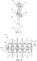
- a vertical-type wire storage frame includes a fixing frame 10a and a master wire wheel set 20a and a slave wire wheel set 30a disposed on the fixing frame 10a, the master wire wheel set 20a and the slave wire wheel set 30a are disposed in parallel, and the master wire wheel set 20a is located above the slave wire wheel set 30a.
- the fixing frame 10a is substantially long-plate-like and disposed vertically, the fixing frame 10a is provided thereon with an open slot 11a, and the open slot 11a is provided thereon with a sliding track 111.
- the master wire wheel set 20a is directly fixed above the fixing frame 10a through a master wire wheel shaft thereof; certainly, the master wire wheel set 20a may also be fixed onto the master wire frame 10a in other manners.
- the slave wire wheel set 30a is disposed on a sliding member 40a, the sliding member 40a has a sliding wheel 41, the sliding member 40a is disposed in the open slot 11a, and the sliding wheel 41 of the sliding member 40a moves up and down on the sliding track 111.
- the sliding member may also be a chain, as long as it can make the slave wire wheel set 30a relatively move relative to the master wire wheel set 20a.
- Both the master wire wheel set 20a and the slave wire wheel set 30a may be a drive wheel set, or the master wire wheel set 20a or the slave wire wheel set 30a is a drive wheel set, and description is given herein by taking the master wire wheel set 20a as a drive wheel set.
- the master wire wheel set 20a When the master wire wheel set 20a is a drive wheel set, the master wire wheel set 20a has a common shaft 21a and several external rotor motors 22a installed on the common shaft 21a, and the common shaft 21a is a shaft of the master wire wheel set.
- the external rotor motors 22a each include a winding stator 221a and an external rotor 222.
- the winding stator 221a is fixed onto the common shaft 21a, provided thereon with coils.
- the external rotor 222 has a magnet, which is pivoted onto the common shaft 21a and disposed outside the winding stator 221a.
- the external rotor 222 is provided thereon with a tube slot 2222.
- the external rotor 222 has a bracket 2221, and the bracket 2221 of the external rotor 222 is pivoted onto the common shaft 21a through a bearing 223.
- the bracket 221a of the external rotor 222 may also be directly pivoted onto the common shaft 21a, and any other manners that can pivot the external rotor 222 onto the common shaft 21a directly or indirectly are feasible.
- the external rotor motor 22a is further provided with a cover body 224.
- the cover body 224 and the external rotor 222 are detachably fixed together, and the cover body 224 is pivoted onto the common shaft 21a through the bearing 223.
- the cover body 224 may also be integrally formed with the external rotor 222.
- the common shaft 21a is provided thereon with a wiring hole 211a extending axially, wherein wire slots 225 are disposed where the common shaft 21a corresponds to each external rotor motor 22a installed thereon, and wire harnesses 226 of the external rotor motor 22a enter into the common shaft 21a through the wire slots 225 and are led out through the wiring hole 211a, which can facilitate wiring and save space.
- the wire harnesses of the external rotor motors 22a may also be led out through gaps between the external rotor motors 22a.
- the coils of the winding stator 221a produce an induced electric field, and the induced electric field repels with a magnetic field produced by the external rotor 222 outside the winding stator 221a, which makes the external rotor 222 rotated.
- the external rotor motors 22a of the drive wheel set can operate separately, the rotating speed of the external rotor of each external rotor motor 22a can be set differently as required, and a control panel that controls each external rotor motor may be disposed on one side of the drive wheel set.
- the external rotor motors 22a of the drive wheel set according to the embodiment of the present application are preferably servo external rotor motors, which can precisely controls the speed of each external rotor motor 22a.
- Each external rotor motor 22a may be further provided with a reducer.
- the reducer is used for adjusting the speed of the drive wheel, to enable the drive wheel to stably operate at a lower speed and output a greater torque during low-speed operation.
- At least one of the master wire wheel set 20a and the slave wire wheel set 30a of the vertical-type wire storage frame according to the embodiment of the present application is a drive wheel set, several external rotor motors 22a of the drive wheel set are disposed on the same common shaft 21a, the distance between two adjacent external rotor motors 22a can be minimized, and the drive wheel set may be small in size, which causes the vertical-type wire storage frame to be small in size and occupy less space.
- the external rotor motors 22a of the drive wheel set of the vertical-type wire storage frame are capable of self-driving, the linear speed of the external rotor motors 22a can be equal to the speed of the tubes on the external rotor motors 22a, no friction force is produced therebetween any more, thus avoiding that the friction between the tubes and the external rotor motors 22a produce wear-out and cutting of external insulation of the tubes and ensuring the quality of the tubes after wire storage.
- the external rotor motors 22a are capable of self-driving, which is no longer provided by a pulling force of the tubes, the pulling force of the tubes decreases; certainly, it is also possible to adjust the external rotor motors 22a as required to make a ratio between the linear speed of the external rotors 22a and the speed of the cables wound on the external rotors 22a decrease the friction force produced by them.
- more external rotor motors can be disposed on the drive wheel set, so as to store more tubes and ensure the quality of the stored tubes.
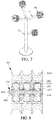
- a swing-type wire storage frame includes a fixing frame 1 and a swing frame 2 pivoted onto the fixing frame 1.
- the fixing frame 1 is substantially long-plate-like and disposed vertically.
- the fixing frame 1 is horizontally provided with a master wire wheel set 10b.
- the master wire wheel set 10b is directly fixed above the fixing frame 1 through a master wire wheel shaft thereof; certainly, the master wire wheel set 10b may also be fixed onto the master wire frame 1 in other manners.
- the swing frame 2 is pivoted onto the fixing frame 1 and pivoted below the master wire wheel set 10b.
- One end of the swing frame 2 is horizontally provided with a slave wire wheel set 20b.
- the swing frame 2 is provided with a counterweight member 3.
- the counterweight member 3 is located on the other end of the swing frame 2 opposite to the slave wire wheel set 20b.
- the counterweight member 3 includes two fixing rods 31, a counterweight adjusting rod 32 disposed between the two fixing rods 31 and a counterweight portion 33 slidable on the counterweight adjusting rod 32.
- Both the master wire wheel set 10 and the slave wire wheel set 20b may be a drive wheel set, or the master wire wheel set 10 or the slave wire wheel set 20b is a drive wheel set, and description is given herein by taking the slave wire wheel set 20b as a drive wheel set.
- the slave wire wheel set 20b When the slave wire wheel set 20b is a drive wheel set, the slave wire wheel set 20b has a common shaft 21b and several external rotor motors 22b installed on the common shaft 21b, and the common shaft 21b is a shaft of the slave wire wheel set.
- the external rotor motors 22b each include a winding stator 221b and an external rotor 222b.
- the winding stator 221b is fixed onto the common shaft 21b, provided thereon with coils.
- the external rotor 222b has a magnet, which is pivoted onto the common shaft 21b and disposed outside the winding stator 221b.
- the external rotor 222b is provided thereon with a tube slot 2222b.
- the external rotor 222b has a bracket 2221b, and the bracket 2221b of the external rotor 222b is pivoted onto the common shaft 21b through a bearing 223b.
- the bracket 221b of the external rotor 222b may also be directly pivoted onto the common shaft 21b, and any other manners that can pivot the external rotor 222b onto the common shaft 21b directly or indirectly are feasible.
- the external rotor motor 22b is further provided with a cover body 224b.
- the cover body 224b and the external rotor 222b are detachably fixed together, and the cover body 224b is pivoted onto the common shaft 21b through the bearing 223b.
- the cover body 224b may also be integrally formed with the external rotor 222b.
- the common shaft 21b is provided thereon with a wiring hole 211b extending axially, wherein wire slots 225b are disposed where the common shaft 21b corresponds to each external rotor motor 22b installed thereon, and wire harnesses of the external rotor motor 22b enter into the common shaft 21b through the wire slots 225b and are led out through the wiring hole 211b, which can facilitate wiring and save space.
- the wire harnesses of the external rotor motors 22b may also be led out through gaps between the external rotor motors 22b.
- the coils of the winding stator 221b produce an induced electric field, and the induced electric field repels with a magnetic field produced by the external rotor 222b outside the winding stator 221b, which makes the external rotor 222b rotated.
- the external rotor motors 22b of the drive wheel set can operate separately, the rotating speed of the external rotor of each external rotor motor 22b can be set differently as required, and a control panel that controls each external rotor motor may be disposed on one side of the drive wheel set.
- the external rotor motors 22b of the drive wheel set according to the embodiment of the present application are preferably servo external rotor motors, which can precisely controls the speed of each external rotor motor 22b.
- Each external rotor motor 22b may be preferably provided with a reducer.
- the reducer is used for adjusting the speed of the drive wheel, to enable the drive wheel to stably operate at a lower speed and output a greater torque during low-speed operation.
- At least one of the master wire wheel set 20b and the slave wire wheel set 30b of the swing-type wire storage frame according to the embodiment of the present application is a drive wheel set, several external rotor motors 22b of the drive wheel set are disposed on the same common shaft 21b, the distance between two adjacent external rotor motors 22b can be minimized, and the drive wheel set may be small in size, which causes the vertical-type wire storage frame to be small in size and occupy less space.
- the external rotor motors 22b of the drive wheel set of the swing-type wire storage frame are capable of self-driving, the linear speed of the external rotor motors 22b can be equal to the speed of the tubes on the external rotor motors 22b, and no friction force is produced therebetween any more, thus avoiding that the friction between the tubes and the external rotor motors 22b produce wear-out and cutting of external insulation of the tubes and ensuring the quality of the tubes after wire storage.
- the external rotor motors 22b are capable of self-driving, which is no longer provided by a pulling force of the tubes, the pulling force of the tubes decreases; certainly, it is also possible to adjust the external rotor motors 22b as required to make a ratio between the linear speed of the external rotors 22b and the speed of the cables wound on the external rotors 22b decrease the friction force produced by them.
- more external rotor motors can be disposed on the drive wheel set, so as to store more tubes and ensure the quality of the stored tubes.
- a guide wheel frame according to the embodiment of the present application includes a fixing frame 1c and several arms 2c fixed onto the fixing frame 1. Each arm 2c is fixed with a wire wheel set 20c.
- the fixing frame 1c is disposed vertically.
- At least one of the several wire wheel sets 20c is a drive wheel set.
- the slave wire wheel set 20c When the wire wheel set 20c is a drive wheel set, the slave wire wheel set 20c has a common shaft 21c and several external rotor motors 22c installed on the common shaft 21c, and the common shaft 21c is a shaft of the slave wire wheel set.
- the external rotor motors 22c each include a winding stator 221c and an external rotor 222c.
- the winding stator 221c is fixed onto the common shaft 21c, provided thereon with coils.
- the external rotor 222c has a magnet, which is pivoted onto the common shaft 21c and disposed outside the winding stator 221c.
- the external rotor 222c is provided thereon with a tube slot 2222c.
- the external rotor 222c has a bracket 2221c, and the bracket 2221c of the external rotor 222c is pivoted onto the common shaft 21c through a bearing 223c.
- the bracket 221c of the external rotor 222c may also be directly pivoted onto the common shaft 21c, and any other manners that can pivot the external rotor 222c onto the common shaft 21c directly or indirectly are feasible.
- the external rotor motor 22c is further provided with a cover body 224c.
- the cover body 224c and the external rotor 222c are detachably fixed together, and the cover body 224c is pivoted onto the common shaft 21c through the bearing 223c.
- the cover body 224c may also be integrally formed with the external rotor 222c.
- the common shaft 21c is provided thereon with a wiring hole 211c extending axially, wherein wire slots 225c are disposed where the common shaft 21c corresponds to each external rotor motor 22c installed thereon, and wire harnesses of the external rotor motor 22c enter into the common shaft 21c through the wire slots 225c and are led out through the wiring hole 211c, which can facilitate wiring and save space.
- the wire harnesses of the external rotor motors 22c may also be led out through gaps between the external rotor motors 22c.
- the external rotor motors 22c of the drive wheel set can operate separately, the rotating speed of the external rotor of each external rotor motor 22c can be set differently as required, and a control panel that controls each external rotor motor may be disposed on one side of the drive wheel set.
- the external rotor motors 22c of the drive wheel set according to the embodiment of the present application are preferably servo external rotor motors, which can precisely controls the speed of each external rotor motor 22c.
- Each external rotor motor 22c may be further provided with a reducer.
- the reducer is used for adjusting the speed of the drive wheel, to enable the drive wheel to stably operate at a lower speed and output a greater torque during low-speed operation.
- At least one of the wire wheel sets 20c of the guide wheel frame according to the embodiment of the present application is a drive wheel set, several external rotor motors 22c of the drive wheel set are disposed on the same common shaft 21c, the distance between two adjacent external rotor motors 22c can be minimized, and the drive wheel set may be small in size, which causes the guide wheel frame to be small in size and occupy less space.
- the external rotor motors 22c of the drive wheel set of the guide wheel frame according to the embodiment of the present application are capable of self-driving, the linear speed of the external rotor motors 22c can be equal to the speed of the tubes on the external rotor motors 22c, and no friction force is produced therebetween any more, thus avoiding that the friction between the tubes and the external rotor motors 22c produce wear-out and cutting of external insulation of the tubes and ensuring the quality of the tubes after wire storage.
- the external rotor motors 22c are capable of self-driving, which is no longer provided by a pulling force of the tubes, the pulling force of the tubes decreases; certainly, it is also possible to adjust the external rotor motors 22c as required to make a ratio between the linear speed of the external rotors 22c and the speed of the cables wound on the external rotors 22c decrease the friction force produced by them.
- a traction mechanism according to the embodiment of the present application includes a fixing frame 10d and a pair of oppositely disposed traction wheel sets 20d fixed onto the fixing frame 10d.
- the fixing frame 10d plays a role of fixing the traction wheel sets 20d.
- the fixing frame 10d is two pairs of fixing plates 11d disposed up and down in parallel.
- Each traction wheel set 20d includes a common shaft 21d and several external rotor motors 22d installed on the common shaft 21d.
- the external rotor motors 22d each include a winding stator 221d and an external rotor 222d.
- the winding stator 221d is fixed onto the common shaft 21d.
- the common shaft 21d is provided with a common shaft key slot 212d
- the winding stator 221d is provided with a stator key slot 2211d.
- the common shaft key slot 212d and the stator key slot 2211d are internally fixed with a buckling key 23d, so as to fix the winding stator 221d onto the common shaft 21d.
- the winding stator 221d may also be fixed onto the common shaft 21d through direct welding, and actually, any other manners that can fix the winding stator 221d onto the common shaft 21d are feasible.
- the external rotor 222d is disposed outside the winding stator 221d and pivoted onto the common shaft 21d.
- the external rotor 222d is preferably pivoted onto the common shaft 21d through a bearing 40d.
- Two common shafts 21d of each pair of the traction wheel sets 20d are disposed in parallel.
- the external rotors 222d of the external rotor motors 22d form traction wheels of the traction wheel sets 20d.
- the traction wheels of each pair of traction wheel sets 20d are disposed in parallel and correspondingly adjacent to each other.
- the two pairs of traction wheel sets 20d are disposed in parallel, common shafts 21d of the two pairs of traction wheel sets 20d are respectively fixed to two ends of the fixing plates 11d, and the traction wheels of one pair of traction wheel sets 20d and the traction wheels of the other pair of traction wheel sets 20d are sleeved with a traction belt 30d.
- the common shaft 21d is provided with a wiring hole 211d extending axially, wherein wire slots 223d are disposed where the common shaft 21d corresponds to the external rotor motors 22d installed thereon, and wire harnesses (not shown) of the external rotor motors 22d enter into the common shaft 21d through the wire slots 223d and are led out through the wiring hole 211d.
- the wire harnesses of the external rotor motors 22d may also be led out through gaps between the external rotor motors 22d.
- the external rotor motor 22d is further provided with a cover body 224d.
- the cover body 224d and the external rotor 222d are detachably fixed together, and the cover body 224d is pivoted onto the common shaft 21d through the bearing 40d.
- a plurality of tube wires 50d are correspondingly pressed between two pairs of traction belts 30d respectively, the external rotor motors 22d of two pairs of traction wheel sets 20d rotate to drive the traction belts 30d to circularly rotate, and the tube wires 50d sandwiched between two traction belts 30d are pulled through rotation of the traction belts 30d.
- the external rotor motors 22d of the traction wheel set can operate separately, the rotating speed of the external rotor of each external rotor motor 22d can be set differently as required, and a control panel that controls each external rotor motor may be disposed on one side of the drive wheel set.
- the fixing plates 11d are provided with receiving holes 111d and threaded end holes 112d disposed along a front-back direction of the two pairs of traction wheel sets.
- the receiving holes 111d receive a shaft fixing block 212d that can move back and forth in the receiving holes.
- the common shaft 21d is fixed onto the shaft fixing block 212d.
- the threaded end holes 112d are fixed with a threaded adjusting length member 60 by thread.
- One end of the threaded adjusting length member 60 is fixed to the shaft fixing block 212d, and the other end of the threaded adjusting length member 60 extends out of the threaded end holes 112d. Adjustment of the threaded adjusting length member 60 can adjust the distance between the two pairs of traction wheel sets 20d, thus adjusting the tightness of the traction belt 30d.
- upper and lower fixing plates 11d on the same side are respectively fixed with a fixing member 12d, wherein one fixing member 12d is provided with a threaded hole 121d, and the threaded hole 121d is provided with a threaded adjusting thickness member 13d.
- One end of the threaded adjusting thickness member 13d extends out of the threaded hole 121d, and the other end of the threaded adjusting thickness member 13d is connected with another fixing member 12d.
- Adjustment of the threaded adjusting thickness member 13d can adjust the distance between upper and lower traction wheels of each pair of traction wheel sets 20d, to adapt to tube wires with different thicknesses and specifications.
- the upper and lower fixing plates 11d on the same side are respectively fixed with a guide fixing member 14d, wherein one guide fixing member 14d is provided with a guide hole 141d, the guide hole 141d is provided with a guide rod 15d, and the other end of the guide rod 15d is connected with the another guide fixing member 14d, which can improve stability of the two pairs of traction wheel sets 20d.
- the traction mechanism may also be merely one pair of traction wheel sets 20d, and when working, tube wires are sandwiched between upper and lower traction wheels of the two traction wheel sets 20d for traction.
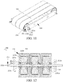
- a multi-path conveying mechanism includes a fixing frame 10e and a pair of oppositely disposed traction wheel sets 20e fixed onto the fixing frame 10e and a plurality of transmission belts 30e.
- the fixing frame 10e plays a role of fixing the traction wheel sets 20e.
- the fixing frame 10e is two pairs of fixing plates 11e disposed up and down in parallel.
- each traction wheel set 20e includes a common shaft 21e and several external rotor motors 22e installed on the common shaft 21e.
- the external rotor motors 22e each include a winding stator 221e and an external rotor 222e.
- the winding stator 221e is fixed onto the common shaft 21e.
- the common shaft 21e is provided with a common shaft key slot 212e
- the winding stator 221e is provided with a stator key slot 2211e.
- the common shaft key slot 212e and the stator key slot 2211e are internally fixed with a buckling key 23e, so as to fix the winding stator 221e onto the common shaft 21e.
- the winding stator 221e may also be fixed onto the common shaft 21e through direct welding, and actually, any other manners that can fix the winding stator 221e onto the common shaft 21e are feasible.
- the external rotor 222e is disposed outside the winding stator 221e and pivoted onto the common shaft 21e.
- the external rotor 222e is preferably pivoted onto the common shaft 21e through a bearing 40e.
- Two common shafts 21e of each pair of the traction wheel sets 20e are disposed in parallel.
- the external rotors 222e of the external rotor motors 22e form traction wheels of the traction wheel sets 20e.
- the two pairs of traction wheel sets 20e are disposed in parallel, common shafts 21e of the two pairs of traction wheel sets 20e are respectively fixed to two ends of the fixing plates 11e, and the traction wheels of one pair of traction wheel sets 20e and the traction wheels of the other pair of traction wheel sets 20e are sleeved with a transmission belt 30e.
- the common shaft 21e is provided with a wiring hole 211e extending axially, wherein wire slots 223e are disposed where the common shaft 21e corresponds to the external rotor motors 22e installed thereon, and wire harnesses (not shown) of the external rotor motors 22e enter into the common shaft 21e through the wire slots 223e and are led out through the wiring hole 211e.
- the wire harnesses of the external rotor motors 22 may also be led out through gaps between the external rotor motors 22e.
- the external rotor motor 22e is further provided with a cover body 224e.
- the cover body 224e and the external rotor 222e are detachably fixed together, and the cover body 224e is pivoted onto the common shaft 21e through the bearing 40e.
- the multi-path conveying mechanism pulls products
- a plurality of products 50e are correspondingly placed on transmission belts 30e respectively
- the external rotor motors 22e of two pairs of traction wheel sets 20e rotate to drive the transmission belts 30e to circularly rotate
- the products 50e placed on the transmission belts 30e are transmitted through rotation of the transmission belts 30e.
- the external rotor motors 22e of the traction wheel set 20e can operate separately, the rotating speed of the external rotor of each external rotor motor 22e can be set differently as required, and a control panel that controls each external rotor motor may be disposed on one side of the drive wheel set.
- the fixing plates 11e are provided with receiving holes 111e and threaded end holes 112e disposed along a front-back direction of the two pairs of traction wheel sets.
- the receiving holes 111e receive a shaft fixing block 212e that can move back and forth in the receiving holes.
- the common shaft 21e is fixed onto the shaft fixing block 212e.
- the threaded end holes 112e are fixed with a threaded adjusting length member 60e by thread.
- One end of the threaded adjusting length member 60e is fixed to the shaft fixing block 212e, and the other end of the threaded adjusting length member 60e extends out of the threaded end holes 112e. Adjustment of the threaded adjusting length member 60e can adjust the distance between the two pairs of traction wheel sets 20e, thus adjusting the tightness of the transmission belt 30e.
Landscapes
- Engineering & Computer Science (AREA)
- Power Engineering (AREA)
- Mechanical Engineering (AREA)
- Arrangement Or Mounting Of Propulsion Units For Vehicles (AREA)
- Storing, Repeated Paying-Out, And Re-Storing Of Elongated Articles (AREA)
Description
- The present application relates to a drive wheel set and a vertical-type wire storage frame, a swing-type wire storage frame, a guide wheel frame, a traction mechanism and a multi-path conveying mechanism having the drive wheel set.
- At present, operation of all kinds of machine equipment is mostly driven by motors. A plurality of motors are required when a plurality of machine equipment is driven, when the plurality of motors are in the same space especially used in parallel, each motor has a shaft, the plurality of motors have a plurality of shafts, and when the plurality of motors are used at the same time, a phenomenon exists that large space is occupied such that the plurality of motors cannot be placed in parallel. This is because, due to the volume of each motor plus a transmission manner of a belt or gear as well as limitations of the existing space, the motor cannot be placed in many places where an active motor should be modulated, and only driven wheels can be used or some functions of the equipment are lost, which may lead to product quality issues.
-
EP2466730A1 disclosed a gearless roller drive. The gearless roller drive has a transverse flux motor that is equipped with an internal stator and an outer rotor. Several permanent magnets are circumferentially arranged one behind the other. The transverse flux unit and an electric control unit are axially arranged one behind the other. The dimensions of the electric control unit radially along axis of the stator, are not more than the rotor diameter. The electrical terminal conductors are connected with the control unit through plug connectors. - During cable manufacturing, it is necessary to use a vertical-type wire storage frame, the vertical-type wire storage frame stores wires when a pay-off reel pays off, to be ready for the pay-off reel to change a reel, when the pay-off reel is empty and needs to change the reel, the vertical-type wire storage frame discharges wires, so as to avoid shutdown of production caused by reel changing of the pay-off reel, thus ensuring large-scale continuous production of the cables. Similarly, the vertical-type wire storage frame may also be used in a situation where a wire storage reel changes a reel, that is, the vertical-type wire storage frame discharges wires when the wire storage reel stores wires, and the vertical-type wire storage frame stores wires when the wire storage reel is full and changes the reel.
- A traditional vertical-type wire storage frame includes a fixing portion, a cushion portion, a master wire wheel set, a master pivot, a slave wire wheel set and a slave pivot, the fixing portion is disposed vertically, one end of the master pivot is fixed onto the fixing portion, the cushion portion is fixed onto the fixing portion and located below the master pivot, one end of the slave pivot is fixed onto the cushion portion, the master pivot and the slave pivot are disposed in parallel, the master wire wheel set is installed on the master pivot, and the slave wire wheel set is installed on the slave pivot. When the vertical-type wire storage frame works, the cables are wound on wire wheels in the master wire wheel set and the slave wire wheel set, the cables drive at a fixed speed, the cables produce friction forces with master wire wheels and slave wire wheels, and the friction forces drive the master wire wheels and the slave wire wheels to rotate.
- However, the wire storage capacity of the vertical-type wire storage frame is less, in order to increase the wire storage capacity of such an apparatus, people use a method of increasing the number of the master wire wheels in the master wire wheel set and the number of the slave wire wheels in the slave wire wheel set, as all the master wire wheels and slave wire wheels belong to idle wheels, only under the pulling force of the cables can they rotate, and to make more master wire wheels and slave wire wheels rotate, a greater cable pulling force is required; as the cables have elasticity, increase of the cable pulling force causes extension of the cables, and the diameter of the cables becomes thin, so that the cables after wire storage are not in line with the quality requirement; secondly, increase of the cable pulling force makes the pressure N of the cables on the wire wheels become great, a friction coefficient u between the cables and the wire wheels is unchanged, and according to a friction force calculation formula f=uN, the friction force between the cables and the wire wheels increases, which leads to wear-out and cutting of external insulation of the cables.
- Chinese Patent Publication
102336348A discloses a vertical-type wire storage frame. The vertical-type wire storage frame is used to solve the problems of wear-out and cutting of external insulation of the cables; however, the master wire wheel set or the slave wire wheel set of the vertical-type wire storage frame has a problem of occupying a relatively large volume when using a drive speed regulating device in the form of a motor. - During manufacturing of cables or tubes, it is necessary to use a swing-type wire storage frame, the swing-type wire storage frame stores wires when a pay-off reel pays off, to be ready for the pay-off reel to change a reel, when the pay-off reel is empty and needs to change the reel, the swing-type wire storage frame discharges wires, so as to avoid shutdown of production caused by reel changing of the pay-off reel, thus ensuring large-scale continuous production of the cables. Similarly, the swing-type wire storage frame may also be used in a situation where a wire storage reel changes a reel, that is, the swing-type wire storage frame discharges wires when the wire storage reel stores wires, and the swing-type wire storage frame stores wires when the wire storage reel is full and changes the reel.
- A traditional swing-type wire storage frame includes a fixing frame and a swing frame. The fixing frame is horizontally provided with a master wire wheel set. The swing frame is pivoted onto the fixing frame and pivoted below the master wire wheel set. One end of the swing frame is horizontally provided with a slave wire wheel set. When working, the swing-type wire storage frame drives the slave wire wheel set to swing through swing of the swing frame, thus achieving storage or release of wires or tubes, the wires or tubes are wound on wire wheels in the master wire wheel set and the slave wire wheel set, the wires or tubes drive at a fixed speed, the cables produce friction forces with master wire wheels and slave wire wheels, and the friction forces drive the master wire wheels and the slave wire wheels to rotate.
- However, the wire storage capacity of the swing-type wire storage frame is less, in order to increase the wire storage capacity of such an apparatus, people use a method of increasing the number of the master wire wheels in the master wire wheel set and the number of the slave wire wheels in the slave wire wheel set, as all the master wire wheels and slave wire wheels belong to idle wheels, only under the pulling force of the cables can they rotate, and to make more master wire wheels and slave wire wheels rotate, a greater cable pulling force is required; as the cables have elasticity, increase of the cable pulling force causes extension of the cables, and the diameter of the cables becomes thin, so that the cables after wire storage are not in line with the quality requirement; secondly, increase of the cable pulling force makes the pressure N of the cables on the wire wheels become great, a friction coefficient u between the cables and the wire wheels is unchanged, and according to a friction force calculation formula f=uN, the friction force between the cables and the wire wheels increases, which leads to wear-out and cutting of external insulation of the cables.
- Chinese Patent Publication
102336348A discloses a wire storage apparatus. The wire storage apparatus is used to solve the problems of wear-out and cutting of external insulation of the cables; however, the master wire wheel set or the slave wire wheel set of the wire storage apparatus has a problem of occupying a relatively large volume when using a drive speed regulating device in the form of a motor. - During manufacturing of cables or tubes, it is necessary to use a guide wheel frame. The guide wheel frame includes a fixing frame and several arms fixed onto the fixing frame. Each arm is fixed with a wire wheel set.
- When the guide wheel frame works, a guide function of the cables or tubes is achieved through the wire wheel set of the guide wheel frame; as the wire wheel set has several wire wheels, several cables or tubes in the same direction can be guided. The wires or tubes are respectively wound on several wire wheels of the wire wheel set to drive at a fixed speed.
- However, rotation of the wire wheels of the wire wheel set is driven by a friction force of the cables or tubes, and the friction force leads to wear-out and cutting of external insulation of the cables or tubes.
- During a manufacturing process of tube wires such as wires, cables or heat-shrinkable tubes, it is necessary to use a traction mechanism to pull the tube wires.
- The current traction mechanism includes two traction wheels oppositely disposed, each of which is driven by an internal rotor motor, has an incompact structure, and occupies great space.
- During a manufacturing process of a product, it is necessary to use a conveying mechanism to convey the product.
- The current conveying mechanism includes two traction wheels oppositely disposed, each of which is driven by an internal rotor motor, has an incompact structure, and occupies great space.
- An object of the present application is to provide a drive wheel set small in size and occupying less space.
- Another object of the present application is to provide a vertical-type wire storage frame which is small in size, has large wire storage capacity and can ensure wire quality after wire storage.
- Another object of the present application is to provide a swing-type wire storage frame which is small in size, has large wire storage capacity and can ensure wire quality after wire storage.
- Another object of the present application is to provide a guide wire frame which is small in size and can avoid wear-out and cutting of external insulation of cables or tubes wound thereon.
- Another object of the present application is to provide a traction mechanism compact in structure and occupying less space.
- Another object of the present application is to provide a multi-path conveying mechanism compact in structure and occupying less space.
- In one aspect, the present application provides a drive wheel set, including a common shaft and at least two external rotor motors installed on the common shaft, external rotors of the external rotor motors forming drive wheels of the drive wheel set.
- Each of the external rotor motors includes a winding stator and an external rotor, the winding stator is fixed onto the common shaft, and the external rotor is disposed outside the winding stator and pivoted onto the common shaft.
- Preferably, the external rotors are permanent magnetic external rotors.
- The winding stators of the external rotor motors and the common shaft are respectively provided with key slots and are fixed into the key slots through buckling keys to fix the winding stators onto the common shaft.
- Preferably, the external rotors of the external rotor motors are pivoted onto the common shaft through bearings.
- The common shaft is provided with a wiring hole extending axially, wherein wire slots are disposed where the common shaft corresponds to the external rotor motors installed thereon, and wire harnesses of the drive wheels enter into the common shaft through the wire slots and are led out through the wiring hole.
- Preferably, the external rotor motor is further provided with a cover body, the cover body and the external rotor are detachably fixed together, and the cover body is pivoted onto the common shaft through a bearing.
- Preferably, the external rotor motors are squirrel-cage asynchronous motors.
- As stated above, as at least two external rotor motors of the drive wheel set of the present application are disposed on the same common shaft, the distance between two adjacent external rotor motors can be minimized, which enables the drive wheel set to be small in size, occupy less space, and suitable for a situation where a plurality of motors need to be driven but sufficient space is lacking.
- In another aspect, the present application provides a vertical-type wire storage frame, including a fixing frame and a master wire wheel set and a slave wire wheel set disposed on the fixing frame, the master wire wheel set and the slave wire wheel set being disposed in parallel, wherein at least one of the master wire wheel set and the slave wire wheel set is any drive wheel set described above.
- As at least one of the master wire wheel set and the slave wire wheel set of the vertical-type wire storage frame of the present application is a drive wheel set, several external rotor motors of the drive wheel set are disposed on the same common shaft, the distance between two adjacent external rotor motors can be minimized, and the drive wheel set may be very small in size, which causes the vertical-type wire storage frame to be small in size and occupy less space.
- The external rotor motors of the drive wheel set of the vertical-type wire storage frame of the present application are capable of self-driving, the linear speed of the external rotor motors can be equal to the speed of the tubes on the external rotor motors, and no friction force is produced therebetween any more, thus avoiding that the friction between the tubes and the external rotor motors produce wear-out and cutting of external insulation of the tubes and ensuring the quality of the tubes after wire storage.
- As the external rotor motors are capable of self-driving, which is no longer provided by a pulling force of the tubes, the pulling force of the tubes decreases; certainly, it is also possible to adjust the external rotor motors as required to make a ratio between the linear speed of the external rotors and the speed of the cables wound on the external rotors decrease the friction force produced by them. Thus, in the vertical-type wire storage frame of the present application, more external rotor motors can be disposed on the drive wheel set, so as to store more tubes and ensure the quality of the stored tubes.
- In another aspect, the present application provides a swing-type wire storage frame, including a fixing frame and a swing frame, the fixing frame being horizontally provided with a master wire wheel set, the swing frame being pivoted onto the fixing frame and pivoted below the master wire wheel set, and one end of the swing frame being horizontally provided with a slave wire wheel set, wherein at least one of the master wire wheel set and the slave wire wheel set is any drive wheel set described above.
- Preferably, the swing frame is further provided with a counterweight member, the counterweight member is located on the other end of the swing frame opposite to the slave wire wheel set, and the counterweight member includes two fixing rods, a counterweight adjusting rod disposed between the two fixing rods and a counterweight portion slidable on the counterweight adjusting rod.
- As at least one of the master wire wheel set and the slave wire wheel set of the swing-type wire storage frame of the present application is a drive wheel set, several external rotor motors of the drive wheel set are disposed on the same common shaft, the distance between two adjacent external rotor motors can be minimized, and the drive wheel set may be very small in size, which causes the swing-type wire storage frame to be small in size and occupy less space.
- The external rotor motors of the drive wheel set of the swing-type wire storage frame of the present application are capable of self-driving, the linear speed of the external rotor motors can be equal to the speed of the tubes on the external rotor motors, and no friction force is produced therebetween any more, thus avoiding that the friction between the tubes and the external rotor motors produce wear-out and cutting of external insulation of the tubes and ensuring the quality of the tubes after wire storage.
- As the external rotor motors are capable of self-driving, which is no longer provided by a pulling force of the tubes, the pulling force of the tubes decreases; certainly, it is also possible to adjust the external rotor motors as required to make a ratio between the linear speed of the external rotors and the speed of the cables wound on the external rotors decrease the friction force produced by them. Thus, in the swing-type wire storage frame of the present application, more external rotor motors can be disposed on the drive wheel set, so as to store more tubes and ensure the quality of the stored tubes.
- In another aspect, the present application provides a guide wheel frame, including a fixing frame and at least two arms fixed onto the fixing frame, each of which is fixed with a wire wheel set, wherein at least one of the wire wheel sets is any drive wheel set described above.
- As at least one of the wire wheel sets of the guide wire frame of the present application is a drive wheel set, several external rotor motors of the drive wheel set are disposed on the same common shaft, the distance between two adjacent external rotor motors can be minimized, and the drive wheel set may be very small in size, which causes the guide wheel frame to be small in size and occupy less space.
- The external rotor motors of the drive wheel set of the guide wire frame of the present application are capable of self-driving, the linear speed of the external rotor motors can be equal to the speed of the tubes on the external rotor motors, and no friction force is produced therebetween any more, thus avoiding that the friction between the tubes and the external rotor motors produce wear-out and cutting of external insulation of the tubes and ensuring the quality of the tubes after wire storage.
- As the external rotor motors are capable of self-driving, which is no longer provided by a pulling force of the tubes, the pulling force of the tubes decreases; certainly, it is also possible to adjust the external rotor motors as required to make a ratio between the linear speed of the external rotors and the speed of the cables wound on the external rotors decrease the friction force produced by them.
- In another aspect, the present application provides a traction mechanism, including a fixing frame and a pair of oppositely disposed traction wheel sets fixed onto the fixing frame, two common shafts of the pair of traction wheel sets being disposed in parallel, and traction wheels in the pair of traction wheel sets being disposed in parallel and correspondingly adjacent to each other, wherein each traction wheel set is any drive wheel set described above, and external rotors of the external rotor motors of the drive wheel set form the traction wheels of the traction wheel sets.
- Preferably, there are two pairs of oppositely disposed traction wheel sets, the two pairs of traction wheel sets are disposed in parallel, the fixing frame is two pairs of fixing plates disposed up and down in parallel, common shafts of the two pairs of traction wheel sets are respectively fixed to two ends of the fixing plates, and the traction wheels of one pair of traction wheel sets and the traction wheels of the other pair of traction wheel sets are sleeved with a traction belt.
- Preferably, the fixing plates are provided with receiving holes and threaded end holes disposed along a front-back direction of the two pairs of traction wheel sets, the receiving holes receive a shaft fixing block that can move back and forth in the receiving holes, the common shaft is fixed onto the shaft fixing block, the threaded end holes are fixed with a threaded adjusting length member by thread, one end of the threaded adjusting length member is fixed to the shaft fixing block, and the other end of the threaded adjusting length member extends out of the threaded end holes.
- Preferably, upper and lower fixing plates on the same side are respectively fixed with a fixing member, wherein one fixing member is provided with a threaded hole, the threaded hole is provided with a threaded adjusting thickness member, one end of the threaded adjusting thickness member extends out of the threaded hole, and the other end of the threaded adjusting thickness member is connected with another fixing member.
- Preferably, the upper and lower fixing plates on the same side are respectively fixed with a guide fixing member, wherein one guide fixing member is provided with a guide hole, the guide hole is provided with a guide rod, and the other end of the guide rod is connected with the another guide fixing member.
- As several external rotor motors of the traction wheel set of the traction mechanism of the present application are installed on the same common shaft, a smaller distance may be set between adjacent external rotor motors, which causes the traction mechanism to be compact in structure and occupy less space.
- In another aspect, the present application provides a multi-path conveying mechanism, including a fixing frame, a pair of oppositely disposed traction wheel sets fixed onto the fixing frame and a plurality of transmission belts, two common shafts of the pair of traction wheel sets being disposed in parallel, wherein a plurality of traction wheels of one traction wheel set and a plurality of traction wheels of the other opposite traction wheel set are respectively sleeved with one of the transmission belts correspondingly, wherein each traction wheel set is any drive wheel set described above, and external rotors of the external rotor motors of the drive wheel set form traction wheels of the traction wheel set.
- Preferably, the fixing frame is two pairs of fixing plates disposed in parallel, and common shafts of one pair of the fixing plates are correspondingly fixed to two ends of the fixing plates respectively.
- Preferably, the fixing plates are provided with receiving holes and threaded end holes disposed along a front-back direction of one pair of the traction wheel sets, the receiving holes receive a shaft fixing block that can move back and forth in the receiving holes, the common shaft is fixed onto the shaft fixing block, the threaded end holes are fixed with a threaded adjusting length member by thread, one end of the threaded adjusting length member is fixed to the shaft fixing block, and the other end of the threaded adjusting length member extends out of the threaded end holes.
- As several external rotor motors of the traction wheel set of the multi-path conveying mechanism of the present application are installed on the same common shaft, a smaller distance may be set between adjacent external rotor motors, which causes the multi-path conveying mechanism to be compact in structure and occupy less space.
- The above has elaborated the features and technical advantages of the present application quite extensively so as to better understand the detailed description of the present application. Other features and advantages of the present application will be described below. Persons skilled in the art should understand that disclosed concepts and specific embodiments can be easily used as bases to modify or design other structures to accomplish the same objective of the present application. Structures and operating methods of new features considered as characteristics of the present application and further objectives and advantages will be better understood from the following description with reference to the accompanying drawings.
-
-
FIG. 1 is a three-dimensional schematic structural diagram of an embodiment of a drive wheel set according to the present application; -
FIG. 2 is a sectional schematic structural diagram of the drive wheel set shown inFIG. 1 ; -
FIG. 3 is a three-dimensional schematic diagram of a vertical-type wire storage frame according to the present application; -
FIG. 4 is an axial sectional diagram of the vertical-type wire storage frame shown inFIG. 3 along a drive wheel set, which is enlarged for ease of viewing; -
FIG. 5 is a three-dimensional schematic diagram of a swing-type wire storage frame according to the present application; -
FIG. 6 is an axial sectional diagram of the swing-type wire storage frame shown inFIG. 5 along a drive wheel set, which is enlarged for ease of viewing; -
FIG. 7 is a three-dimensional schematic diagram of a guide wheel frame according to the present application; -
FIG. 8 is an axial sectional diagram of the guide wheel frame shown inFIG. 7 along a drive wheel set, which is enlarged for ease of viewing; -
FIG. 9 is a three-dimensional schematic diagram of a traction mechanism according to the present application; -
FIG. 10 is a schematic sectional diagram of a pair of traction wheel sets of the traction mechanism shown inFIG. 9 , which is enlarged for ease of viewing; -
FIG. 11 is a three-dimensional schematic diagram of a multi-path conveying mechanism according to the present application; and -
FIG. 12 is a schematic sectional diagram of a pair of traction wheel sets of the multi-path conveying mechanism shown inFIG. 11 , which is enlarged for ease of viewing. - Embodiments of the present application are described in detail below with reference to the accompanying drawings. It should be emphasized that the following description is merely illustrative instead of limiting the scope of the present application and applications thereof.
- Referring to
FIG. 1 and FIG. 2 , a drive wheel set according to an embodiment of the present application includes acommon shaft 10 and at least twoexternal rotor motors 20 installed on thecommon shaft 10. - The
external rotor motors 20 each include a windingstator 21 and anexternal rotor 22, and theexternal rotors 22 of the external rotor motors form drive wheels of the drive wheel set. - The winding
stator 21 is fixed onto thecommon shaft 10, provided thereon with coils. - In one embodiment, the
common shaft 10 is provided with a common shaftkey slot 11, and the windingstator 21 is provided with a statorkey slot 211. The common shaftkey slot 11 and the statorkey slot 211 are internally fixed with a bucklingkey 30, so as to fix the windingstator 21 onto thecommon shaft 10. The windingstator 21 may also be fixed onto thecommon shaft 10 through direct welding, and actually, any other manners that can fix the windingstator 21 onto thecommon shaft 10 are feasible. - The
external rotor 22 has a magnet, which is pivoted onto thecommon shaft 10 and disposed outside the windingstator 21. Theexternal rotor 22 is preferably a permanent magnetic external rotor. - In one embodiment, the
external rotor 22 has abracket 221, and thebracket 221 of theexternal rotor 22 is pivoted onto thecommon shaft 10 through abearing 40. Thebracket 221 of theexternal rotor 22 may also be directly pivoted onto thecommon shaft 10, and any other manners that can pivot theexternal rotor 22 onto thecommon shaft 10 directly or indirectly are feasible. - In order to further prevent dust, the
external rotor motor 20 is further provided with acover body 23. Thecover body 23 and theexternal rotor 22 are detachably fixed together, and thecover body 23 is pivoted onto thecommon shaft 10 through thebearing 40. Certainly, thecover body 23 may also be integrally formed with theexternal rotor motor 20. - The
common shaft 10 is provided with awiring hole 12 extending axially, whereinwire slots 13 are disposed where thecommon shaft 10 corresponds to theexternal rotor motors 20 installed thereon, and wire harnesses 50 of eachexternal rotor motor 20 enter into the common shaft through thewire slots 13 and are led out through thewiring hole 12, which can facilitate wiring and save space. According to an embodiment not falling under the claims, the wire harnesses of theexternal rotor motors 20 may also be led out through gaps between theexternal rotor motors 20. - When the drive wheel set according to the embodiment of the present application works, power is supplied for the winding
stator 21 of eachexternal rotor motor 20 respectively through the wire harnesses 50, the coils of the windingstator 21 produce an induced electric field, and the induced electric field repels with a magnetic field produced by theexternal rotor 22 outside the windingstator 21, which makes theexternal rotor 22 rotated. - The
external rotor motors 20 of the drive wheel set can operate separately, the rotating speed of the external rotor of eachexternal rotor motor 20 can be set differently as required, and a control panel that controls each external rotor motor may be disposed on one side of the drive wheel set. - The
external rotor motors 20 of the drive wheel set according to the embodiment of the present application are preferably servo external rotor motors, which can precisely controls the speed of theexternal rotor 22 of eachexternal rotor motor 20. - To sum up, at least two
external rotor motors 20 of the drive wheel set according to the embodiment of the present application are disposed on the samecommon shaft 10, and the distance between two adjacentexternal rotor motors 20 can be minimized, which enables the drive wheel set to be small in size, occupy less space, and suitable for a situation where a plurality of motors need to be driven but sufficient space is lacking. - In addition, each external rotor motor may be further provided with a reducer. The reducer is used for adjusting the speed of the drive wheel, to enable the drive wheel to stably operate at a lower speed and output a greater torque during low-speed operation.
- Referring to
FIG. 3 and FIG. 4 , a vertical-type wire storage frame according to an embodiment of the present application includes a fixingframe 10a and a masterwire wheel set 20a and a slavewire wheel set 30a disposed on the fixingframe 10a, the masterwire wheel set 20a and the slavewire wheel set 30a are disposed in parallel, and the masterwire wheel set 20a is located above the slavewire wheel set 30a. - The fixing
frame 10a is substantially long-plate-like and disposed vertically, the fixingframe 10a is provided thereon with anopen slot 11a, and theopen slot 11a is provided thereon with a slidingtrack 111. - In one embodiment, the master
wire wheel set 20a is directly fixed above the fixingframe 10a through a master wire wheel shaft thereof; certainly, the masterwire wheel set 20a may also be fixed onto themaster wire frame 10a in other manners. - The slave
wire wheel set 30a is disposed on a slidingmember 40a, the slidingmember 40a has a slidingwheel 41, the slidingmember 40a is disposed in theopen slot 11a, and the slidingwheel 41 of the slidingmember 40a moves up and down on the slidingtrack 111. - Certainly, the sliding member may also be a chain, as long as it can make the slave
wire wheel set 30a relatively move relative to the masterwire wheel set 20a. - Both the master
wire wheel set 20a and the slavewire wheel set 30a may be a drive wheel set, or the masterwire wheel set 20a or the slavewire wheel set 30a is a drive wheel set, and description is given herein by taking the masterwire wheel set 20a as a drive wheel set. - When the master
wire wheel set 20a is a drive wheel set, the masterwire wheel set 20a has acommon shaft 21a and severalexternal rotor motors 22a installed on thecommon shaft 21a, and thecommon shaft 21a is a shaft of the master wire wheel set. - The
external rotor motors 22a each include a windingstator 221a and anexternal rotor 222. - The winding
stator 221a is fixed onto thecommon shaft 21a, provided thereon with coils. - The
external rotor 222 has a magnet, which is pivoted onto thecommon shaft 21a and disposed outside the windingstator 221a. - The
external rotor 222 is provided thereon with atube slot 2222. - In one embodiment, the
external rotor 222 has abracket 2221, and thebracket 2221 of theexternal rotor 222 is pivoted onto thecommon shaft 21a through abearing 223. Thebracket 221a of theexternal rotor 222 may also be directly pivoted onto thecommon shaft 21a, and any other manners that can pivot theexternal rotor 222 onto thecommon shaft 21a directly or indirectly are feasible. - In order to further prevent dust, the
external rotor motor 22a is further provided with acover body 224. Thecover body 224 and theexternal rotor 222 are detachably fixed together, and thecover body 224 is pivoted onto thecommon shaft 21a through thebearing 223. Certainly, thecover body 224 may also be integrally formed with theexternal rotor 222. - The
common shaft 21a is provided thereon with awiring hole 211a extending axially, whereinwire slots 225 are disposed where thecommon shaft 21a corresponds to eachexternal rotor motor 22a installed thereon, and wire harnesses 226 of theexternal rotor motor 22a enter into thecommon shaft 21a through thewire slots 225 and are led out through thewiring hole 211a, which can facilitate wiring and save space. According to an embodiment not falling under the claims, the wire harnesses of theexternal rotor motors 22a may also be led out through gaps between theexternal rotor motors 22a. - When the drive wheel set according to the embodiment of the present application works, the coils of the winding
stator 221a produce an induced electric field, and the induced electric field repels with a magnetic field produced by theexternal rotor 222 outside the windingstator 221a, which makes theexternal rotor 222 rotated. - The
external rotor motors 22a of the drive wheel set can operate separately, the rotating speed of the external rotor of eachexternal rotor motor 22a can be set differently as required, and a control panel that controls each external rotor motor may be disposed on one side of the drive wheel set. - The
external rotor motors 22a of the drive wheel set according to the embodiment of the present application are preferably servo external rotor motors, which can precisely controls the speed of eachexternal rotor motor 22a. - Each
external rotor motor 22a may be further provided with a reducer. The reducer is used for adjusting the speed of the drive wheel, to enable the drive wheel to stably operate at a lower speed and output a greater torque during low-speed operation. - Several
external rotor motors 22a of the drive wheel set are disposed on the samecommon shaft 21a, and the distance between two adjacentexternal rotor motors 22a can be minimized, which enables the drive wheel set to be small in size, occupy less space, and suitable for a situation where a plurality of motors need to be driven but sufficient space is lacking. - At least one of the master
wire wheel set 20a and the slavewire wheel set 30a of the vertical-type wire storage frame according to the embodiment of the present application is a drive wheel set, severalexternal rotor motors 22a of the drive wheel set are disposed on the samecommon shaft 21a, the distance between two adjacentexternal rotor motors 22a can be minimized, and the drive wheel set may be small in size, which causes the vertical-type wire storage frame to be small in size and occupy less space. - The
external rotor motors 22a of the drive wheel set of the vertical-type wire storage frame according to the embodiment of the present application are capable of self-driving, the linear speed of theexternal rotor motors 22a can be equal to the speed of the tubes on theexternal rotor motors 22a, no friction force is produced therebetween any more, thus avoiding that the friction between the tubes and theexternal rotor motors 22a produce wear-out and cutting of external insulation of the tubes and ensuring the quality of the tubes after wire storage. - As the
external rotor motors 22a are capable of self-driving, which is no longer provided by a pulling force of the tubes, the pulling force of the tubes decreases; certainly, it is also possible to adjust theexternal rotor motors 22a as required to make a ratio between the linear speed of theexternal rotors 22a and the speed of the cables wound on theexternal rotors 22a decrease the friction force produced by them. Thus, in the vertical-type wire storage frame according to the embodiment of the present application, more external rotor motors can be disposed on the drive wheel set, so as to store more tubes and ensure the quality of the stored tubes. - Referring to
FIG. 5 and FIG. 6 , a swing-type wire storage frame includes a fixingframe 1 and a swing frame 2 pivoted onto the fixingframe 1. - The fixing
frame 1 is substantially long-plate-like and disposed vertically. The fixingframe 1 is horizontally provided with a masterwire wheel set 10b. In one embodiment, the masterwire wheel set 10b is directly fixed above the fixingframe 1 through a master wire wheel shaft thereof; certainly, the masterwire wheel set 10b may also be fixed onto themaster wire frame 1 in other manners. - The swing frame 2 is pivoted onto the fixing
frame 1 and pivoted below the masterwire wheel set 10b. One end of the swing frame 2 is horizontally provided with a slavewire wheel set 20b. The swing frame 2 is provided with a counterweight member 3. The counterweight member 3 is located on the other end of the swing frame 2 opposite to the slavewire wheel set 20b. The counterweight member 3 includes two fixingrods 31, acounterweight adjusting rod 32 disposed between the two fixingrods 31 and acounterweight portion 33 slidable on thecounterweight adjusting rod 32. - Both the master wire wheel set 10 and the slave
wire wheel set 20b may be a drive wheel set, or the master wire wheel set 10 or the slavewire wheel set 20b is a drive wheel set, and description is given herein by taking the slavewire wheel set 20b as a drive wheel set. - When the slave
wire wheel set 20b is a drive wheel set, the slavewire wheel set 20b has acommon shaft 21b and severalexternal rotor motors 22b installed on thecommon shaft 21b, and thecommon shaft 21b is a shaft of the slave wire wheel set. - The
external rotor motors 22b each include a windingstator 221b and anexternal rotor 222b. - The winding
stator 221b is fixed onto thecommon shaft 21b, provided thereon with coils. - The
external rotor 222b has a magnet, which is pivoted onto thecommon shaft 21b and disposed outside the windingstator 221b. - The
external rotor 222b is provided thereon with atube slot 2222b. - In one embodiment, the
external rotor 222b has abracket 2221b, and thebracket 2221b of theexternal rotor 222b is pivoted onto thecommon shaft 21b through abearing 223b. Thebracket 221b of theexternal rotor 222b may also be directly pivoted onto thecommon shaft 21b, and any other manners that can pivot theexternal rotor 222b onto thecommon shaft 21b directly or indirectly are feasible. - In order to further prevent dust, the
external rotor motor 22b is further provided with acover body 224b. Thecover body 224b and theexternal rotor 222b are detachably fixed together, and thecover body 224b is pivoted onto thecommon shaft 21b through thebearing 223b. Certainly, thecover body 224b may also be integrally formed with theexternal rotor 222b. - The
common shaft 21b is provided thereon with awiring hole 211b extending axially, whereinwire slots 225b are disposed where thecommon shaft 21b corresponds to eachexternal rotor motor 22b installed thereon, and wire harnesses of theexternal rotor motor 22b enter into thecommon shaft 21b through thewire slots 225b and are led out through thewiring hole 211b, which can facilitate wiring and save space. According to an embodiment not falling under the claims, the wire harnesses of theexternal rotor motors 22b may also be led out through gaps between theexternal rotor motors 22b. - When the drive wheel set according to the embodiment of the present application works, the coils of the winding
stator 221b produce an induced electric field, and the induced electric field repels with a magnetic field produced by theexternal rotor 222b outside the windingstator 221b, which makes theexternal rotor 222b rotated. - The
external rotor motors 22b of the drive wheel set can operate separately, the rotating speed of the external rotor of eachexternal rotor motor 22b can be set differently as required, and a control panel that controls each external rotor motor may be disposed on one side of the drive wheel set. - The
external rotor motors 22b of the drive wheel set according to the embodiment of the present application are preferably servo external rotor motors, which can precisely controls the speed of eachexternal rotor motor 22b. - Each
external rotor motor 22b may be preferably provided with a reducer. The reducer is used for adjusting the speed of the drive wheel, to enable the drive wheel to stably operate at a lower speed and output a greater torque during low-speed operation. - Several
external rotor motors 22b of the drive wheel set are disposed on the samecommon shaft 21b, and the distance between two adjacentexternal rotor motors 22b can be minimized, which enables the drive wheel set to be small in size, occupy less space, and suitable for a situation where a plurality of motors need to be driven but sufficient space is lacking. - At least one of the master
wire wheel set 20b and the slave wire wheel set 30b of the swing-type wire storage frame according to the embodiment of the present application is a drive wheel set, severalexternal rotor motors 22b of the drive wheel set are disposed on the samecommon shaft 21b, the distance between two adjacentexternal rotor motors 22b can be minimized, and the drive wheel set may be small in size, which causes the vertical-type wire storage frame to be small in size and occupy less space. - The
external rotor motors 22b of the drive wheel set of the swing-type wire storage frame according to the embodiment of the present application are capable of self-driving, the linear speed of theexternal rotor motors 22b can be equal to the speed of the tubes on theexternal rotor motors 22b, and no friction force is produced therebetween any more, thus avoiding that the friction between the tubes and theexternal rotor motors 22b produce wear-out and cutting of external insulation of the tubes and ensuring the quality of the tubes after wire storage. - As the
external rotor motors 22b are capable of self-driving, which is no longer provided by a pulling force of the tubes, the pulling force of the tubes decreases; certainly, it is also possible to adjust theexternal rotor motors 22b as required to make a ratio between the linear speed of theexternal rotors 22b and the speed of the cables wound on theexternal rotors 22b decrease the friction force produced by them. Thus, in the swing-type wire storage frame according to the embodiment of the present application, more external rotor motors can be disposed on the drive wheel set, so as to store more tubes and ensure the quality of the stored tubes. - Referring to
FIG. 7 and FIG. 8 , a guide wheel frame according to the embodiment of the present application includes a fixingframe 1c andseveral arms 2c fixed onto the fixingframe 1. Eacharm 2c is fixed with awire wheel set 20c. - The fixing
frame 1c is disposed vertically. - At least one of the several
wire wheel sets 20c is a drive wheel set. - When the
wire wheel set 20c is a drive wheel set, the slavewire wheel set 20c has acommon shaft 21c and severalexternal rotor motors 22c installed on thecommon shaft 21c, and thecommon shaft 21c is a shaft of the slave wire wheel set. - The
external rotor motors 22c each include a windingstator 221c and anexternal rotor 222c. - The winding
stator 221c is fixed onto thecommon shaft 21c, provided thereon with coils. - The
external rotor 222c has a magnet, which is pivoted onto thecommon shaft 21c and disposed outside the windingstator 221c. - The
external rotor 222c is provided thereon with atube slot 2222c. - In one embodiment, the
external rotor 222c has abracket 2221c, and thebracket 2221c of theexternal rotor 222c is pivoted onto thecommon shaft 21c through abearing 223c. Thebracket 221c of theexternal rotor 222c may also be directly pivoted onto thecommon shaft 21c, and any other manners that can pivot theexternal rotor 222c onto thecommon shaft 21c directly or indirectly are feasible. - In order to further prevent dust, the
external rotor motor 22c is further provided with acover body 224c. Thecover body 224c and theexternal rotor 222c are detachably fixed together, and thecover body 224c is pivoted onto thecommon shaft 21c through thebearing 223c. Certainly, thecover body 224c may also be integrally formed with theexternal rotor 222c. - The
common shaft 21c is provided thereon with awiring hole 211c extending axially, whereinwire slots 225c are disposed where thecommon shaft 21c corresponds to eachexternal rotor motor 22c installed thereon, and wire harnesses of theexternal rotor motor 22c enter into thecommon shaft 21c through thewire slots 225c and are led out through thewiring hole 211c, which can facilitate wiring and save space. According to an embodiment not falling under the claims, the wire harnesses of theexternal rotor motors 22c may also be led out through gaps between theexternal rotor motors 22c. - The
external rotor motors 22c of the drive wheel set can operate separately, the rotating speed of the external rotor of eachexternal rotor motor 22c can be set differently as required, and a control panel that controls each external rotor motor may be disposed on one side of the drive wheel set. - The
external rotor motors 22c of the drive wheel set according to the embodiment of the present application are preferably servo external rotor motors, which can precisely controls the speed of eachexternal rotor motor 22c. - Each
external rotor motor 22c may be further provided with a reducer. The reducer is used for adjusting the speed of the drive wheel, to enable the drive wheel to stably operate at a lower speed and output a greater torque during low-speed operation. - Several
external rotor motors 22c of the drive wheel set are disposed on the samecommon shaft 21c, and the distance between two adjacentexternal rotor motors 22c can be minimized, which enables the drive wheel set to be small in size, occupy less space, and suitable for a situation where a plurality of motors need to be driven but sufficient space is lacking. - At least one of the wire wheel sets 20c of the guide wheel frame according to the embodiment of the present application is a drive wheel set, several
external rotor motors 22c of the drive wheel set are disposed on the samecommon shaft 21c, the distance between two adjacentexternal rotor motors 22c can be minimized, and the drive wheel set may be small in size, which causes the guide wheel frame to be small in size and occupy less space. - The
external rotor motors 22c of the drive wheel set of the guide wheel frame according to the embodiment of the present application are capable of self-driving, the linear speed of theexternal rotor motors 22c can be equal to the speed of the tubes on theexternal rotor motors 22c, and no friction force is produced therebetween any more, thus avoiding that the friction between the tubes and theexternal rotor motors 22c produce wear-out and cutting of external insulation of the tubes and ensuring the quality of the tubes after wire storage. - As the
external rotor motors 22c are capable of self-driving, which is no longer provided by a pulling force of the tubes, the pulling force of the tubes decreases; certainly, it is also possible to adjust theexternal rotor motors 22c as required to make a ratio between the linear speed of theexternal rotors 22c and the speed of the cables wound on theexternal rotors 22c decrease the friction force produced by them. - Referring to
FIG. 9 and FIG. 10 , a traction mechanism according to the embodiment of the present application includes a fixingframe 10d and a pair of oppositely disposedtraction wheel sets 20d fixed onto the fixingframe 10d. - The fixing
frame 10d plays a role of fixing thetraction wheel sets 20d. In one embodiment, the fixingframe 10d is two pairs of fixingplates 11d disposed up and down in parallel. - In one embodiment, there are two pairs of oppositely disposed
traction wheel sets 20d. Eachtraction wheel set 20d includes acommon shaft 21d and severalexternal rotor motors 22d installed on thecommon shaft 21d. Theexternal rotor motors 22d each include a windingstator 221d and anexternal rotor 222d. - The winding
stator 221d is fixed onto thecommon shaft 21d. In one embodiment, thecommon shaft 21d is provided with a common shaftkey slot 212d, and the windingstator 221d is provided with a statorkey slot 2211d. The common shaftkey slot 212d and the statorkey slot 2211d are internally fixed with a buckling key 23d, so as to fix the windingstator 221d onto thecommon shaft 21d. The windingstator 221d may also be fixed onto thecommon shaft 21d through direct welding, and actually, any other manners that can fix the windingstator 221d onto thecommon shaft 21d are feasible. - The
external rotor 222d is disposed outside the windingstator 221d and pivoted onto thecommon shaft 21d. Theexternal rotor 222d is preferably pivoted onto thecommon shaft 21d through abearing 40d. Twocommon shafts 21d of each pair of thetraction wheel sets 20d are disposed in parallel. Theexternal rotors 222d of theexternal rotor motors 22d form traction wheels of thetraction wheel sets 20d. The traction wheels of each pair oftraction wheel sets 20d are disposed in parallel and correspondingly adjacent to each other. - The two pairs of
traction wheel sets 20d are disposed in parallel,common shafts 21d of the two pairs oftraction wheel sets 20d are respectively fixed to two ends of the fixingplates 11d, and the traction wheels of one pair oftraction wheel sets 20d and the traction wheels of the other pair oftraction wheel sets 20d are sleeved with atraction belt 30d. - The
common shaft 21d is provided with awiring hole 211d extending axially, whereinwire slots 223d are disposed where thecommon shaft 21d corresponds to theexternal rotor motors 22d installed thereon, and wire harnesses (not shown) of theexternal rotor motors 22d enter into thecommon shaft 21d through thewire slots 223d and are led out through thewiring hole 211d. According to an embodiment not falling under the claims, the wire harnesses of theexternal rotor motors 22d may also be led out through gaps between theexternal rotor motors 22d. - Preferably, the
external rotor motor 22d is further provided with acover body 224d. Thecover body 224d and theexternal rotor 222d are detachably fixed together, and thecover body 224d is pivoted onto thecommon shaft 21d through thebearing 40d. - When the traction mechanism according to the embodiment of the present application pulls tube wires, a plurality of
tube wires 50d are correspondingly pressed between two pairs oftraction belts 30d respectively, theexternal rotor motors 22d of two pairs oftraction wheel sets 20d rotate to drive thetraction belts 30d to circularly rotate, and thetube wires 50d sandwiched between twotraction belts 30d are pulled through rotation of thetraction belts 30d. - The
external rotor motors 22d of the traction wheel set can operate separately, the rotating speed of the external rotor of eachexternal rotor motor 22d can be set differently as required, and a control panel that controls each external rotor motor may be disposed on one side of the drive wheel set. - Several
external rotor motors 22d of thetraction wheel set 20d of the traction mechanism according to the embodiment of the present application are installed on the samecommon shaft 21d, and a smaller distance may be set between adjacentexternal rotor motors 22d, which causes the traction mechanism to be compact in structure and occupy less space. - Preferably, the fixing
plates 11d are provided with receivingholes 111d and threaded end holes 112d disposed along a front-back direction of the two pairs of traction wheel sets. The receiving holes 111d receive ashaft fixing block 212d that can move back and forth in the receiving holes. Thecommon shaft 21d is fixed onto theshaft fixing block 212d. The threaded end holes 112d are fixed with a threaded adjusting length member 60 by thread. One end of the threaded adjusting length member 60 is fixed to theshaft fixing block 212d, and the other end of the threaded adjusting length member 60 extends out of the threaded end holes 112d. Adjustment of the threaded adjusting length member 60 can adjust the distance between the two pairs oftraction wheel sets 20d, thus adjusting the tightness of thetraction belt 30d. - Preferably, upper and
lower fixing plates 11d on the same side are respectively fixed with a fixingmember 12d, wherein one fixingmember 12d is provided with a threadedhole 121d, and the threadedhole 121d is provided with a threadedadjusting thickness member 13d. One end of the threadedadjusting thickness member 13d extends out of the threadedhole 121d, and the other end of the threadedadjusting thickness member 13d is connected with another fixingmember 12d. Adjustment of the threadedadjusting thickness member 13d can adjust the distance between upper and lower traction wheels of each pair oftraction wheel sets 20d, to adapt to tube wires with different thicknesses and specifications. - Preferably, the upper and
lower fixing plates 11d on the same side are respectively fixed with aguide fixing member 14d, wherein oneguide fixing member 14d is provided with aguide hole 141d, theguide hole 141d is provided with aguide rod 15d, and the other end of theguide rod 15d is connected with the anotherguide fixing member 14d, which can improve stability of the two pairs oftraction wheel sets 20d. - It should be pointed out that the above are preferred embodiments of the embodiments of the present application, the traction mechanism may also be merely one pair of
traction wheel sets 20d, and when working, tube wires are sandwiched between upper and lower traction wheels of the twotraction wheel sets 20d for traction. - To sum up, several
external rotor motors 22d of thetraction wheel set 20d of the traction mechanism according to the embodiment of the present application are installed on the samecommon shaft 21d, and a smaller distance may be set between adjacentexternal rotor motors 22d, which causes the traction mechanism to be compact in structure and occupy less space. - Referring to
FIG. 11 and FIG. 12 , a multi-path conveying mechanism according to the embodiment of the present application includes a fixingframe 10e and a pair of oppositely disposedtraction wheel sets 20e fixed onto the fixingframe 10e and a plurality oftransmission belts 30e. - The fixing
frame 10e plays a role of fixing thetraction wheel sets 20e. In one embodiment, the fixingframe 10e is two pairs of fixing plates 11e disposed up and down in parallel. - In one embodiment, each
traction wheel set 20e includes acommon shaft 21e and severalexternal rotor motors 22e installed on thecommon shaft 21e. Theexternal rotor motors 22e each include a windingstator 221e and anexternal rotor 222e. - The winding
stator 221e is fixed onto thecommon shaft 21e. In one embodiment, thecommon shaft 21e is provided with a common shaftkey slot 212e, and the windingstator 221e is provided with a statorkey slot 2211e. The common shaftkey slot 212e and the statorkey slot 2211e are internally fixed with a buckling key 23e, so as to fix the windingstator 221e onto thecommon shaft 21e. The windingstator 221e may also be fixed onto thecommon shaft 21e through direct welding, and actually, any other manners that can fix the windingstator 221e onto thecommon shaft 21e are feasible. - The
external rotor 222e is disposed outside the windingstator 221e and pivoted onto thecommon shaft 21e. Theexternal rotor 222e is preferably pivoted onto thecommon shaft 21e through abearing 40e. Twocommon shafts 21e of each pair of thetraction wheel sets 20e are disposed in parallel. Theexternal rotors 222e of theexternal rotor motors 22e form traction wheels of thetraction wheel sets 20e. - The two pairs of
traction wheel sets 20e are disposed in parallel,common shafts 21e of the two pairs oftraction wheel sets 20e are respectively fixed to two ends of the fixing plates 11e, and the traction wheels of one pair oftraction wheel sets 20e and the traction wheels of the other pair oftraction wheel sets 20e are sleeved with atransmission belt 30e. - The
common shaft 21e is provided with awiring hole 211e extending axially, whereinwire slots 223e are disposed where thecommon shaft 21e corresponds to theexternal rotor motors 22e installed thereon, and wire harnesses (not shown) of theexternal rotor motors 22e enter into thecommon shaft 21e through thewire slots 223e and are led out through thewiring hole 211e. According to an embodiment not falling under the claims, the wire harnesses of theexternal rotor motors 22 may also be led out through gaps between theexternal rotor motors 22e. - Preferably, the
external rotor motor 22e is further provided with acover body 224e. Thecover body 224e and theexternal rotor 222e are detachably fixed together, and thecover body 224e is pivoted onto thecommon shaft 21e through thebearing 40e. - When the multi-path conveying mechanism according to the embodiment of the present application pulls products, a plurality of products 50e are correspondingly placed on
transmission belts 30e respectively, theexternal rotor motors 22e of two pairs oftraction wheel sets 20e rotate to drive thetransmission belts 30e to circularly rotate, and the products 50e placed on thetransmission belts 30e are transmitted through rotation of thetransmission belts 30e. - The
external rotor motors 22e of thetraction wheel set 20e can operate separately, the rotating speed of the external rotor of eachexternal rotor motor 22e can be set differently as required, and a control panel that controls each external rotor motor may be disposed on one side of the drive wheel set. - Several
external rotor motors 22e of thetraction wheel set 20e of the multi-path conveying mechanism according to the embodiment of the present application are installed on the samecommon shaft 21e, and a smaller distance may be set between adjacentexternal rotor motors 22e, which causes the traction mechanism to be compact in structure and occupy less space. - Preferably, the fixing plates 11e are provided with receiving
holes 111e and threadedend holes 112e disposed along a front-back direction of the two pairs of traction wheel sets. The receivingholes 111e receive ashaft fixing block 212e that can move back and forth in the receiving holes. Thecommon shaft 21e is fixed onto theshaft fixing block 212e. The threadedend holes 112e are fixed with a threadedadjusting length member 60e by thread. One end of the threadedadjusting length member 60e is fixed to theshaft fixing block 212e, and the other end of the threadedadjusting length member 60e extends out of the threadedend holes 112e. Adjustment of the threadedadjusting length member 60e can adjust the distance between the two pairs oftraction wheel sets 20e, thus adjusting the tightness of thetransmission belt 30e. - To sum up, several
external rotor motors 22e of thetraction wheel set 20e of the multi-path conveying mechanism according to the embodiment of the present application are installed on the samecommon shaft 21e, and a smaller distance may be set between adjacentexternal rotor motors 22e, which causes the traction mechanism to be compact in structure and occupy less space. - Although the present application is described above in further detail through specific embodiments, the present application is not limited to the specific embodiments. Although the present application and advantages thereof have been described in detail, it should be understood by persons of ordinary skill in the art that various changes, replacements and modifications can be made within the scope of the present invention as defined by the appended claims. In addition, the application scope of the present application is not limited to specific embodiments of the processes, machines, manufacturing, material composition, manners, methods and steps described in the description.
Claims (13)
- A drive wheel set, comprising a common shaft (10) and at least two external rotor motors (20) installed on the common shaft, external rotors (22) of the external rotor motors forming drive wheels of the drive wheel set, wherein each of the external rotor motors comprises a winding stator (21) and an external rotor (22), the winding stator is fixed onto the common shaft, and the external rotor is disposed outside the winding stator and pivoted onto the common shaft, wherein an induced electric field produced by the coils of the winding stator repels with a magnetic field produced by the external rotor outside the winding stator so as to make the external rotor rotated, wherein
the common shaft is provided with a wiring hole (12) extending axially, characterized in that wire slots (13), extending radially through a sidewall of the common shaft and extending radially into the external rotor, are disposed where the common shaft corresponds to the external rotor motors installed thereon, and wire harnesses of the drive wheels enter into the common shaft through the wire slots and are led out through the wiring hole, and that
the winding stators of the external rotor motors and the common shaft are respectively provided with key slots (211, 11) and are fixed into the key slots through buckling keys (30) to fix the winding stators onto the common shaft. - A vertical-type wire storage frame, characterized by comprising a fixing frame (10a) and a master wire wheel set (20a) and a slave wire wheel set (30a) disposed on the fixing frame, the master wire wheel set and the slave wire wheel set being disposed in parallel, wherein at least one of the master wire wheel set and the slave wire wheel set is the drive wheel set according to claim 1.
- A swing-type wire storage frame, characterized by comprising a fixing frame (1) and a swing frame (2), the fixing frame being horizontally provided with a master wire wheel set, the swing frame being pivoted onto the fixing frame and pivoted below the master wire wheel set, and one end of the swing frame being horizontally provided with a slave wire wheel set (20b), wherein at least one of the master wire wheel set and the slave wire wheel set is the drive wheel set according to claim 1.
- The swing-type wire storage frame according to claim 3, characterized in that the swing frame is further provided with a counterweight member (3), the counterweight member is located on the other end of the swing frame opposite to the slave wire wheel set, and the counterweight member comprises two fixing rods (31), a counterweight adjusting rod (32) disposed between the two fixing rods and a counterweight portion (33) slidable on the counterweight adjusting rod.
- A guide wheel frame, characterized by comprising a fixing frame (1c) and at least two arms (2c) fixed onto the fixing frame, each of which is fixed with a wire wheel set (20c), wherein at least one of the wire wheel sets is the drive wheel set according to claim 1.
- A traction mechanism, characterized by comprising a fixing frame (10d) and a pair of oppositely disposed traction wheel sets (20d) fixed onto the fixing frame, two common shafts (21d) of the pair of traction wheel sets being disposed in parallel, and traction wheels in the pair of traction wheel sets being disposed in parallel and correspondingly adjacent to each other, wherein each traction wheel set is the drive wheel set according to claim 1, and external rotors (222d) of the external rotor motors (22d) of the drive wheel set form the traction wheels of the traction wheel sets.
- The traction mechanism according to claim 6, characterized in that there are two pairs of oppositely disposed traction wheel sets, the two pairs of traction wheel sets are disposed in parallel, the fixing frame is two pairs of fixing plates (11d) disposed up and down in parallel, common shafts of the two pairs of traction wheel sets are respectively fixed to two ends of the fixing plates, and the traction wheels of one pair of traction wheel sets and the traction wheels of the other pair of traction wheel sets are sleeved with a traction belt (30d).
- The traction mechanism according to claim 7, characterized in that the fixing plates are provided with receiving holes (111d) and threaded end holes (112d) disposed along a front-back direction of the two pairs of traction wheel sets, the receiving holes receive a shaft fixing block (212d) that can move back and forth in the receiving holes, the common shaft is fixed onto the shaft fixing block, the threaded end holes are fixed with a threaded adjusting length member (60) by thread, one end of the threaded adjusting length member is fixed to the shaft fixing block, and the other end of the threaded adjusting length member extends out of the threaded end holes.
- The traction mechanism according to claim 7, characterized in that upper and lower fixing plates on the same side are respectively fixed with a fixing member (12d), wherein one fixing member is provided with a threaded hole (121d), the threaded hole is provided with a threaded adjusting thickness member (13d), one end of the threaded adjusting thickness member extends out of the threaded hole, and the other end of the threaded adjusting thickness member is connected with another fixing member.
- The traction mechanism according to claim 9, characterized in that the upper and lower fixing plates on the same side are respectively fixed with a guide fixing member (14d), wherein one guide fixing member is provided with a guide hole (141d), the guide hole is provided with a guide rod (15d), and the other end of the guide rod is connected with the another guide fixing member.
- A multi-path conveying mechanism, characterized by comprising a fixing frame (10e), a pair of oppositely disposed traction wheel sets (20e) fixed onto the fixing frame and a plurality of transmission belts (30e), two common shafts (21e) of the pair of traction wheel sets being disposed in parallel, wherein a plurality of traction wheels of one traction wheel set and a plurality of traction wheels of the other opposite traction wheel set are respectively sleeved with one of the transmission belts correspondingly, wherein each traction wheel set is the drive wheel set according to claim 1, and external rotors (222e) of the external rotor motors (22e) of the drive wheel set form traction wheels of the traction wheel set.
- The multi-path conveying mechanism according to claim 11, characterized in that the fixing frame is two pairs of fixing plates (11e) disposed in parallel, and common shafts of one pair of the fixing plates are correspondingly fixed to two ends of the fixing plates respectively.
- The multi-path conveying mechanism according to claim 12, characterized in that the fixing plates are provided with receiving holes (111e) and threaded end holes (112e) disposed along a front-back direction of one pair of the traction wheel sets, the receiving holes receive a shaft fixing block (212e) that can move back and forth in the receiving holes, the common shaft is fixed onto the shaft fixing block, the threaded end holes are fixed with a threaded adjusting length member (60e) by thread, one end of the threaded adjusting length member is fixed to the shaft fixing block, and the other end of the threaded adjusting length member extends out of the threaded end holes.
Applications Claiming Priority (1)
| Application Number | Priority Date | Filing Date | Title |
|---|---|---|---|
| PCT/CN2013/091222 WO2015100668A1 (en) | 2013-12-31 | 2013-12-31 | Drive wheel set, wire storage frame, guide wheel frame, traction mechanism and conveying mechanism |
Publications (3)
| Publication Number | Publication Date |
|---|---|
| EP3091643A1 EP3091643A1 (en) | 2016-11-09 |
| EP3091643A4 EP3091643A4 (en) | 2017-10-04 |
| EP3091643B1 true EP3091643B1 (en) | 2019-12-18 |
Family
ID=53493006
Family Applications (1)
| Application Number | Title | Priority Date | Filing Date |
|---|---|---|---|
| EP13900747.0A Active EP3091643B1 (en) | 2013-12-31 | 2013-12-31 | Drive wheel set, wire storage frame, guide wheel frame, traction mechanism and conveying mechanism |
Country Status (3)
| Country | Link |
|---|---|
| US (1) | US9840393B2 (en) |
| EP (1) | EP3091643B1 (en) |
| WO (1) | WO2015100668A1 (en) |
Families Citing this family (17)
| Publication number | Priority date | Publication date | Assignee | Title |
|---|---|---|---|---|
| DE102015113435A1 (en) * | 2015-08-14 | 2017-02-16 | Khs Gmbh | Transport device and transport method with such a transport device |
| DE102016112051B4 (en) * | 2016-06-30 | 2024-01-04 | Interroll Holding Ag | Modular system for motor-driven conveyor rollers |
| CN106516887B (en) * | 2016-12-30 | 2022-09-06 | 深圳市特发信息光网科技股份有限公司 | Wire storage device capable of automatically adjusting length difference of double cables on line |
| CN106986240B (en) * | 2017-05-11 | 2018-01-30 | 安徽理工大学 | A kind of electronic three tunnels synchronization take-up and pay-off device |
| CN109143519B (en) * | 2018-08-21 | 2020-05-15 | 河北奥科通信科技有限公司 | An improved communication optical cable fixing device |
| DE102018008272A1 (en) * | 2018-10-18 | 2020-04-23 | Heuft Systemtechnik Gmbh | Transport device with several rotating cylinders and clamping belts |
| USD877838S1 (en) * | 2018-10-20 | 2020-03-10 | Thomas William Bird | Pool Ball Rack |
| CN109353882A (en) * | 2018-11-20 | 2019-02-19 | 国网河南省电力公司孟津县供电公司 | A power line tie-wrap |
| CN111268508A (en) * | 2018-12-04 | 2020-06-12 | 怀化宇隆电工材料有限公司 | Positioning guide device for enameled wire production line |
| CN109473850B (en) * | 2018-12-27 | 2023-10-24 | 武汉华中激光产业有限公司 | Automatic stranded wire contact pin production machine |
| IT201900001845A1 (en) | 2019-02-08 | 2020-08-08 | Tesmec Spa | CABLE RECOVERY MACHINE |
| IT201900001841A1 (en) * | 2019-02-08 | 2020-08-08 | Tesmec Spa | CABLE RECOVERY MACHINE |
| EP3766814B1 (en) * | 2019-07-16 | 2024-09-04 | Komax Holding Ag | Cable supply device, cable processing system and method for feeding a cable to a cable processing machine |
| CN112141805B (en) * | 2020-09-22 | 2021-12-10 | 合肥神马科技集团有限公司 | Cable traction method using tire tractor |
| CN114988208B (en) * | 2022-04-27 | 2024-01-09 | 神宇通信科技股份公司 | Coaxial cable production height adjusting device |
| CN117341168B (en) * | 2023-10-13 | 2025-08-19 | 长飞光纤光缆股份有限公司 | Optical cable secondary plastic coating traction device and traction method |
| CN119525353B (en) * | 2025-01-23 | 2025-08-15 | 赣州鑫冠科技股份有限公司 | Die stamping integrated system with die stamping force fine adjustment structure |
Family Cites Families (21)
| Publication number | Priority date | Publication date | Assignee | Title |
|---|---|---|---|---|
| GB205162A (en) | 1922-07-06 | 1923-10-08 | Anderson John | Improvements in and relating to indicating devices for prepayment mechanism |
| DE1602237B2 (en) * | 1967-06-02 | 1976-07-01 | Berkenhoff & Drebes AG Asslar, Zweigniederlassung, 6349 Merkenbach | SPOOL OR WINDING DEVICE FOR WINDING A SPOOL WITH STRANDED OR THREAD-SHAPED GOODS, SUCH AS WIRE |
| DE7016570U (en) * | 1970-05-02 | 1971-02-25 | Glanzstoff Ag | ADJUSTABLE GALLET EXTRACTOR. |
| DE4115485A1 (en) * | 1991-05-11 | 1992-11-12 | Mulfingen Elektrobau Ebm | DRIVE UNIT FOR DOUBLE FAN |
| DE10340593B4 (en) * | 2003-09-01 | 2016-01-21 | Caterpillar Global Mining Europe Gmbh | Drive device for chain stars of chain drives |
| FR2870837A1 (en) * | 2004-05-26 | 2005-12-02 | Rieter Textile Machinery Fr | Friction drive for filiform element such as textile yarn has track on outer surface of hollow cylindrical body forming rotor of motor with permanent magnets |
| JP4974118B2 (en) * | 2005-02-12 | 2012-07-11 | アプライド マテリアルズ インコーポレイテッド | Multi-axis vacuum motor assembly |
| DE102006005158A1 (en) * | 2006-02-04 | 2007-08-16 | Abb Patent Gmbh | Drive drum of a belt conveyor and modular system for forming a drive drum |
| DE102008035091A1 (en) * | 2008-07-28 | 2010-02-11 | Airbus Deutschland Gmbh | Drive device for use in transportation unit for independent driving of two bodies arranged coaxially with each other, has two stators, two rotors and holder for twist-proof fastening of drive device |
| CN201825592U (en) * | 2010-06-13 | 2011-05-11 | 深圳市沃尔核材股份有限公司 | Wire storing device |
| DE102010031252A1 (en) * | 2010-07-12 | 2012-01-12 | Von Ardenne Anlagentechnik Gmbh | Substrate treatment facility |
| CN102336348A (en) * | 2010-07-20 | 2012-02-01 | 深圳市沃尔核材股份有限公司 | Wire storing device |
| EP2466730A1 (en) * | 2010-12-20 | 2012-06-20 | Cyoris Ag | Gearless roller drive |
| CN102624148A (en) * | 2012-03-28 | 2012-08-01 | 大连理工大学 | An integrated dual-output coaxial motor |
| CN203048298U (en) * | 2012-12-31 | 2013-07-10 | 慈溪市宏晟机械设备有限公司 | Wire feeding device |
| CN203699555U (en) * | 2013-12-31 | 2014-07-09 | 深圳市沃尔核材股份有限公司 | Vertical wire storage rack |
| CN203699538U (en) * | 2013-12-31 | 2014-07-09 | 深圳市沃尔核材股份有限公司 | Guide wheel carrier |
| CN203699152U (en) * | 2013-12-31 | 2014-07-09 | 深圳市沃尔核材股份有限公司 | Traction mechanism |
| CN203699541U (en) * | 2013-12-31 | 2014-07-09 | 深圳市沃尔核材股份有限公司 | Oscillating wire storage rack |
| CN203699153U (en) * | 2013-12-31 | 2014-07-09 | 深圳市沃尔核材股份有限公司 | Multi-way conveying mechanism |
| CN103701261B (en) * | 2013-12-31 | 2017-01-18 | 深圳市沃尔核材股份有限公司 | Driving wheel set |
-
2013
- 2013-12-31 EP EP13900747.0A patent/EP3091643B1/en active Active
- 2013-12-31 WO PCT/CN2013/091222 patent/WO2015100668A1/en not_active Ceased
-
2016
- 2016-06-30 US US15/198,573 patent/US9840393B2/en active Active
Non-Patent Citations (1)
| Title |
|---|
| None * |
Also Published As
| Publication number | Publication date |
|---|---|
| EP3091643A1 (en) | 2016-11-09 |
| US9840393B2 (en) | 2017-12-12 |
| EP3091643A4 (en) | 2017-10-04 |
| US20160355369A1 (en) | 2016-12-08 |
| WO2015100668A1 (en) | 2015-07-09 |
Similar Documents
| Publication | Publication Date | Title |
|---|---|---|
| US9840393B2 (en) | Drive wheel set, wire storage frame, guide wheel frame, traction mechanism and conveying mechanism | |
| CN203699555U (en) | Vertical wire storage rack | |
| CN117012464A (en) | A stranding machine for flexible cable processing | |
| CN118571567A (en) | Bow-shaped stranded wire equipment for high-speed stranded conductor | |
| CN203699541U (en) | Oscillating wire storage rack | |
| CN210925598U (en) | A new type of twisting device | |
| CN213595588U (en) | Wire paying-off, twisting and winding device | |
| CN107633923B (en) | Metal wire assembling machine | |
| CN217533346U (en) | Novel line structure is walked to pot formula yarn machine of bundling | |
| CN103701261B (en) | Driving wheel set | |
| CN203699538U (en) | Guide wheel carrier | |
| CN102254633A (en) | Conducting wire back-twisting mechanism of cabling device | |
| CN212209041U (en) | Production device for high-speed stranded wire | |
| CN205240916U (en) | Cable -placing device | |
| CN114628087B (en) | Winding and coiling machine for compound stranded wire | |
| CN220115908U (en) | Cable coil winding machine | |
| CN220672296U (en) | Traction mechanism with adjustable lay length | |
| CN216613561U (en) | Cable processing is with not shutting down shaft changing mechanism | |
| CN114843038B (en) | Compact structure's embedded stranding machine | |
| CN112885534B (en) | A multifunctional wire twisting machine | |
| CN216435544U (en) | Wire stranding machine | |
| CN205676057U (en) | Electric coiling machine | |
| CN214476671U (en) | A tubular stranding machine for cable processing | |
| CN110950164A (en) | Electric power engineering's hank mill | |
| CN219202852U (en) | Tinned wire stranded conductor device |
Legal Events
| Date | Code | Title | Description |
|---|---|---|---|
| PUAI | Public reference made under article 153(3) epc to a published international application that has entered the european phase |
Free format text: ORIGINAL CODE: 0009012 |
|
| 17P | Request for examination filed |
Effective date: 20160729 |
|
| AK | Designated contracting states |
Kind code of ref document: A1 Designated state(s): AL AT BE BG CH CY CZ DE DK EE ES FI FR GB GR HR HU IE IS IT LI LT LU LV MC MK MT NL NO PL PT RO RS SE SI SK SM TR |
|
| AX | Request for extension of the european patent |
Extension state: BA ME |
|
| DAX | Request for extension of the european patent (deleted) | ||
| A4 | Supplementary search report drawn up and despatched |
Effective date: 20170901 |
|
| RIC1 | Information provided on ipc code assigned before grant |
Ipc: B65H 51/32 20060101ALI20170828BHEP Ipc: H02K 7/14 20060101ALI20170828BHEP Ipc: B65H 75/00 20060101ALI20170828BHEP Ipc: H02K 16/00 20060101ALI20170828BHEP Ipc: B65G 15/14 20060101ALI20170828BHEP Ipc: B65H 51/04 20060101ALI20170828BHEP Ipc: B65G 23/23 20060101ALI20170828BHEP Ipc: H02K 7/20 20060101AFI20170828BHEP Ipc: B65H 57/14 20060101ALI20170828BHEP Ipc: B65H 51/20 20060101ALI20170828BHEP Ipc: B65G 15/20 20060101ALI20170828BHEP Ipc: B65H 51/12 20060101ALI20170828BHEP Ipc: H02K 21/22 20060101ALI20170828BHEP |
|
| STAA | Information on the status of an ep patent application or granted ep patent |
Free format text: STATUS: EXAMINATION IS IN PROGRESS |
|
| 17Q | First examination report despatched |
Effective date: 20181016 |
|
| GRAP | Despatch of communication of intention to grant a patent |
Free format text: ORIGINAL CODE: EPIDOSNIGR1 |
|
| STAA | Information on the status of an ep patent application or granted ep patent |
Free format text: STATUS: GRANT OF PATENT IS INTENDED |
|
| INTG | Intention to grant announced |
Effective date: 20190729 |
|
| GRAS | Grant fee paid |
Free format text: ORIGINAL CODE: EPIDOSNIGR3 |
|
| GRAA | (expected) grant |
Free format text: ORIGINAL CODE: 0009210 |
|
| STAA | Information on the status of an ep patent application or granted ep patent |
Free format text: STATUS: THE PATENT HAS BEEN GRANTED |
|
| AK | Designated contracting states |
Kind code of ref document: B1 Designated state(s): AL AT BE BG CH CY CZ DE DK EE ES FI FR GB GR HR HU IE IS IT LI LT LU LV MC MK MT NL NO PL PT RO RS SE SI SK SM TR |
|
| REG | Reference to a national code |
Ref country code: CH Ref legal event code: EP |
|
| REG | Reference to a national code |
Ref country code: IE Ref legal event code: FG4D |
|
| REG | Reference to a national code |
Ref country code: DE Ref legal event code: R096 Ref document number: 602013064247 Country of ref document: DE |
|
| REG | Reference to a national code |
Ref country code: AT Ref legal event code: REF Ref document number: 1215652 Country of ref document: AT Kind code of ref document: T Effective date: 20200115 |
|
| REG | Reference to a national code |
Ref country code: NL Ref legal event code: MP Effective date: 20191218 |
|
| PG25 | Lapsed in a contracting state [announced via postgrant information from national office to epo] |
Ref country code: NO Free format text: LAPSE BECAUSE OF FAILURE TO SUBMIT A TRANSLATION OF THE DESCRIPTION OR TO PAY THE FEE WITHIN THE PRESCRIBED TIME-LIMIT Effective date: 20200318 Ref country code: GR Free format text: LAPSE BECAUSE OF FAILURE TO SUBMIT A TRANSLATION OF THE DESCRIPTION OR TO PAY THE FEE WITHIN THE PRESCRIBED TIME-LIMIT Effective date: 20200319 Ref country code: LT Free format text: LAPSE BECAUSE OF FAILURE TO SUBMIT A TRANSLATION OF THE DESCRIPTION OR TO PAY THE FEE WITHIN THE PRESCRIBED TIME-LIMIT Effective date: 20191218 Ref country code: BG Free format text: LAPSE BECAUSE OF FAILURE TO SUBMIT A TRANSLATION OF THE DESCRIPTION OR TO PAY THE FEE WITHIN THE PRESCRIBED TIME-LIMIT Effective date: 20200318 Ref country code: FI Free format text: LAPSE BECAUSE OF FAILURE TO SUBMIT A TRANSLATION OF THE DESCRIPTION OR TO PAY THE FEE WITHIN THE PRESCRIBED TIME-LIMIT Effective date: 20191218 Ref country code: LV Free format text: LAPSE BECAUSE OF FAILURE TO SUBMIT A TRANSLATION OF THE DESCRIPTION OR TO PAY THE FEE WITHIN THE PRESCRIBED TIME-LIMIT Effective date: 20191218 Ref country code: SE Free format text: LAPSE BECAUSE OF FAILURE TO SUBMIT A TRANSLATION OF THE DESCRIPTION OR TO PAY THE FEE WITHIN THE PRESCRIBED TIME-LIMIT Effective date: 20191218 |
|
| REG | Reference to a national code |
Ref country code: LT Ref legal event code: MG4D |
|
| PG25 | Lapsed in a contracting state [announced via postgrant information from national office to epo] |
Ref country code: RS Free format text: LAPSE BECAUSE OF FAILURE TO SUBMIT A TRANSLATION OF THE DESCRIPTION OR TO PAY THE FEE WITHIN THE PRESCRIBED TIME-LIMIT Effective date: 20191218 Ref country code: HR Free format text: LAPSE BECAUSE OF FAILURE TO SUBMIT A TRANSLATION OF THE DESCRIPTION OR TO PAY THE FEE WITHIN THE PRESCRIBED TIME-LIMIT Effective date: 20191218 |
|
| PG25 | Lapsed in a contracting state [announced via postgrant information from national office to epo] |
Ref country code: AL Free format text: LAPSE BECAUSE OF FAILURE TO SUBMIT A TRANSLATION OF THE DESCRIPTION OR TO PAY THE FEE WITHIN THE PRESCRIBED TIME-LIMIT Effective date: 20191218 |
|
| PG25 | Lapsed in a contracting state [announced via postgrant information from national office to epo] |
Ref country code: EE Free format text: LAPSE BECAUSE OF FAILURE TO SUBMIT A TRANSLATION OF THE DESCRIPTION OR TO PAY THE FEE WITHIN THE PRESCRIBED TIME-LIMIT Effective date: 20191218 Ref country code: CZ Free format text: LAPSE BECAUSE OF FAILURE TO SUBMIT A TRANSLATION OF THE DESCRIPTION OR TO PAY THE FEE WITHIN THE PRESCRIBED TIME-LIMIT Effective date: 20191218 Ref country code: NL Free format text: LAPSE BECAUSE OF FAILURE TO SUBMIT A TRANSLATION OF THE DESCRIPTION OR TO PAY THE FEE WITHIN THE PRESCRIBED TIME-LIMIT Effective date: 20191218 Ref country code: RO Free format text: LAPSE BECAUSE OF FAILURE TO SUBMIT A TRANSLATION OF THE DESCRIPTION OR TO PAY THE FEE WITHIN THE PRESCRIBED TIME-LIMIT Effective date: 20191218 Ref country code: PT Free format text: LAPSE BECAUSE OF FAILURE TO SUBMIT A TRANSLATION OF THE DESCRIPTION OR TO PAY THE FEE WITHIN THE PRESCRIBED TIME-LIMIT Effective date: 20200513 |
|
| REG | Reference to a national code |
Ref country code: CH Ref legal event code: PL |
|
| REG | Reference to a national code |
Ref country code: BE Ref legal event code: MM Effective date: 20191231 |
|
| PG25 | Lapsed in a contracting state [announced via postgrant information from national office to epo] |
Ref country code: SK Free format text: LAPSE BECAUSE OF FAILURE TO SUBMIT A TRANSLATION OF THE DESCRIPTION OR TO PAY THE FEE WITHIN THE PRESCRIBED TIME-LIMIT Effective date: 20191218 Ref country code: SM Free format text: LAPSE BECAUSE OF FAILURE TO SUBMIT A TRANSLATION OF THE DESCRIPTION OR TO PAY THE FEE WITHIN THE PRESCRIBED TIME-LIMIT Effective date: 20191218 Ref country code: IS Free format text: LAPSE BECAUSE OF FAILURE TO SUBMIT A TRANSLATION OF THE DESCRIPTION OR TO PAY THE FEE WITHIN THE PRESCRIBED TIME-LIMIT Effective date: 20200418 |
|
| REG | Reference to a national code |
Ref country code: DE Ref legal event code: R097 Ref document number: 602013064247 Country of ref document: DE |
|
| PG25 | Lapsed in a contracting state [announced via postgrant information from national office to epo] |
Ref country code: MC Free format text: LAPSE BECAUSE OF FAILURE TO SUBMIT A TRANSLATION OF THE DESCRIPTION OR TO PAY THE FEE WITHIN THE PRESCRIBED TIME-LIMIT Effective date: 20191218 |
|
| REG | Reference to a national code |
Ref country code: AT Ref legal event code: MK05 Ref document number: 1215652 Country of ref document: AT Kind code of ref document: T Effective date: 20191218 |
|
| PLBE | No opposition filed within time limit |
Free format text: ORIGINAL CODE: 0009261 |
|
| STAA | Information on the status of an ep patent application or granted ep patent |
Free format text: STATUS: NO OPPOSITION FILED WITHIN TIME LIMIT |
|
| PG25 | Lapsed in a contracting state [announced via postgrant information from national office to epo] |
Ref country code: DK Free format text: LAPSE BECAUSE OF FAILURE TO SUBMIT A TRANSLATION OF THE DESCRIPTION OR TO PAY THE FEE WITHIN THE PRESCRIBED TIME-LIMIT Effective date: 20191218 Ref country code: LU Free format text: LAPSE BECAUSE OF NON-PAYMENT OF DUE FEES Effective date: 20191231 Ref country code: IE Free format text: LAPSE BECAUSE OF NON-PAYMENT OF DUE FEES Effective date: 20191231 Ref country code: ES Free format text: LAPSE BECAUSE OF FAILURE TO SUBMIT A TRANSLATION OF THE DESCRIPTION OR TO PAY THE FEE WITHIN THE PRESCRIBED TIME-LIMIT Effective date: 20191218 |
|
| 26N | No opposition filed |
Effective date: 20200921 |
|
| PG25 | Lapsed in a contracting state [announced via postgrant information from national office to epo] |
Ref country code: AT Free format text: LAPSE BECAUSE OF FAILURE TO SUBMIT A TRANSLATION OF THE DESCRIPTION OR TO PAY THE FEE WITHIN THE PRESCRIBED TIME-LIMIT Effective date: 20191218 Ref country code: BE Free format text: LAPSE BECAUSE OF NON-PAYMENT OF DUE FEES Effective date: 20191231 Ref country code: LI Free format text: LAPSE BECAUSE OF NON-PAYMENT OF DUE FEES Effective date: 20191231 Ref country code: SI Free format text: LAPSE BECAUSE OF FAILURE TO SUBMIT A TRANSLATION OF THE DESCRIPTION OR TO PAY THE FEE WITHIN THE PRESCRIBED TIME-LIMIT Effective date: 20191218 Ref country code: CH Free format text: LAPSE BECAUSE OF NON-PAYMENT OF DUE FEES Effective date: 20191231 |
|
| PG25 | Lapsed in a contracting state [announced via postgrant information from national office to epo] |
Ref country code: IT Free format text: LAPSE BECAUSE OF FAILURE TO SUBMIT A TRANSLATION OF THE DESCRIPTION OR TO PAY THE FEE WITHIN THE PRESCRIBED TIME-LIMIT Effective date: 20191218 |
|
| PG25 | Lapsed in a contracting state [announced via postgrant information from national office to epo] |
Ref country code: PL Free format text: LAPSE BECAUSE OF FAILURE TO SUBMIT A TRANSLATION OF THE DESCRIPTION OR TO PAY THE FEE WITHIN THE PRESCRIBED TIME-LIMIT Effective date: 20191218 |
|
| PG25 | Lapsed in a contracting state [announced via postgrant information from national office to epo] |
Ref country code: CY Free format text: LAPSE BECAUSE OF FAILURE TO SUBMIT A TRANSLATION OF THE DESCRIPTION OR TO PAY THE FEE WITHIN THE PRESCRIBED TIME-LIMIT Effective date: 20191218 |
|
| PG25 | Lapsed in a contracting state [announced via postgrant information from national office to epo] |
Ref country code: HU Free format text: LAPSE BECAUSE OF FAILURE TO SUBMIT A TRANSLATION OF THE DESCRIPTION OR TO PAY THE FEE WITHIN THE PRESCRIBED TIME-LIMIT; INVALID AB INITIO Effective date: 20131231 Ref country code: MT Free format text: LAPSE BECAUSE OF FAILURE TO SUBMIT A TRANSLATION OF THE DESCRIPTION OR TO PAY THE FEE WITHIN THE PRESCRIBED TIME-LIMIT Effective date: 20191218 |
|
| PG25 | Lapsed in a contracting state [announced via postgrant information from national office to epo] |
Ref country code: TR Free format text: LAPSE BECAUSE OF FAILURE TO SUBMIT A TRANSLATION OF THE DESCRIPTION OR TO PAY THE FEE WITHIN THE PRESCRIBED TIME-LIMIT Effective date: 20191218 |
|
| PG25 | Lapsed in a contracting state [announced via postgrant information from national office to epo] |
Ref country code: MK Free format text: LAPSE BECAUSE OF FAILURE TO SUBMIT A TRANSLATION OF THE DESCRIPTION OR TO PAY THE FEE WITHIN THE PRESCRIBED TIME-LIMIT Effective date: 20191218 |
|
| PGFP | Annual fee paid to national office [announced via postgrant information from national office to epo] |
Ref country code: DE Payment date: 20251211 Year of fee payment: 13 |
|
| PGFP | Annual fee paid to national office [announced via postgrant information from national office to epo] |
Ref country code: GB Payment date: 20251219 Year of fee payment: 13 |
|
| PGFP | Annual fee paid to national office [announced via postgrant information from national office to epo] |
Ref country code: FR Payment date: 20251223 Year of fee payment: 13 |