EP3091218A1 - Electromagnetic fuel injector with optimization of the welds - Google Patents
Electromagnetic fuel injector with optimization of the welds Download PDFInfo
- Publication number
- EP3091218A1 EP3091218A1 EP16168518.5A EP16168518A EP3091218A1 EP 3091218 A1 EP3091218 A1 EP 3091218A1 EP 16168518 A EP16168518 A EP 16168518A EP 3091218 A1 EP3091218 A1 EP 3091218A1
- Authority
- EP
- European Patent Office
- Prior art keywords
- supporting body
- armature
- extension
- fixed armature
- fixed
- Prior art date
- Legal status (The legal status is an assumption and is not a legal conclusion. Google has not performed a legal analysis and makes no representation as to the accuracy of the status listed.)
- Granted
Links
Images



Classifications
-
- F—MECHANICAL ENGINEERING; LIGHTING; HEATING; WEAPONS; BLASTING
- F02—COMBUSTION ENGINES; HOT-GAS OR COMBUSTION-PRODUCT ENGINE PLANTS
- F02M—SUPPLYING COMBUSTION ENGINES IN GENERAL WITH COMBUSTIBLE MIXTURES OR CONSTITUENTS THEREOF
- F02M61/00—Fuel-injectors not provided for in groups F02M39/00 - F02M57/00 or F02M67/00
- F02M61/16—Details not provided for in, or of interest apart from, the apparatus of groups F02M61/02 - F02M61/14
- F02M61/166—Selection of particular materials
-
- F—MECHANICAL ENGINEERING; LIGHTING; HEATING; WEAPONS; BLASTING
- F02—COMBUSTION ENGINES; HOT-GAS OR COMBUSTION-PRODUCT ENGINE PLANTS
- F02M—SUPPLYING COMBUSTION ENGINES IN GENERAL WITH COMBUSTIBLE MIXTURES OR CONSTITUENTS THEREOF
- F02M51/00—Fuel-injection apparatus characterised by being operated electrically
- F02M51/06—Injectors peculiar thereto with means directly operating the valve needle
- F02M51/061—Injectors peculiar thereto with means directly operating the valve needle using electromagnetic operating means
- F02M51/0614—Injectors peculiar thereto with means directly operating the valve needle using electromagnetic operating means characterised by arrangement of electromagnets or fixed armature
- F02M51/0617—Injectors peculiar thereto with means directly operating the valve needle using electromagnetic operating means characterised by arrangement of electromagnets or fixed armature having two or more electromagnets
-
- F—MECHANICAL ENGINEERING; LIGHTING; HEATING; WEAPONS; BLASTING
- F02—COMBUSTION ENGINES; HOT-GAS OR COMBUSTION-PRODUCT ENGINE PLANTS
- F02M—SUPPLYING COMBUSTION ENGINES IN GENERAL WITH COMBUSTIBLE MIXTURES OR CONSTITUENTS THEREOF
- F02M51/00—Fuel-injection apparatus characterised by being operated electrically
- F02M51/06—Injectors peculiar thereto with means directly operating the valve needle
- F02M51/061—Injectors peculiar thereto with means directly operating the valve needle using electromagnetic operating means
- F02M51/0625—Injectors peculiar thereto with means directly operating the valve needle using electromagnetic operating means characterised by arrangement of mobile armatures
- F02M51/0664—Injectors peculiar thereto with means directly operating the valve needle using electromagnetic operating means characterised by arrangement of mobile armatures having a cylindrically or partly cylindrically shaped armature, e.g. entering the winding; having a plate-shaped or undulated armature entering the winding
- F02M51/0671—Injectors peculiar thereto with means directly operating the valve needle using electromagnetic operating means characterised by arrangement of mobile armatures having a cylindrically or partly cylindrically shaped armature, e.g. entering the winding; having a plate-shaped or undulated armature entering the winding the armature having an elongated valve body attached thereto
-
- F—MECHANICAL ENGINEERING; LIGHTING; HEATING; WEAPONS; BLASTING
- F02—COMBUSTION ENGINES; HOT-GAS OR COMBUSTION-PRODUCT ENGINE PLANTS
- F02M—SUPPLYING COMBUSTION ENGINES IN GENERAL WITH COMBUSTIBLE MIXTURES OR CONSTITUENTS THEREOF
- F02M2200/00—Details of fuel-injection apparatus, not otherwise provided for
- F02M2200/80—Fuel injection apparatus manufacture, repair or assembly
- F02M2200/8084—Fuel injection apparatus manufacture, repair or assembly involving welding or soldering
Definitions
- the present invention relates to an electromagnetic fuel injector.
- An electromagnetic fuel injector (for example like the one described in patent application EP1619384A2 ) normally comprises a cylindrical, tubular supporting body provided with a central feeding channel which performs the function of a fuel duct and ends with an injection jet controlled by an injection valve operated by an electromagnetic actuator.
- the injection valve is provided with a plunger, which is displaced by the action of the electromagnetic actuator between a closed position and an open position of the injection jet against the action of a closing spring which pushes the plunger towards the closed position.
- the electromagnet comprises a coil, which is arranged on the outside and in a fixed position around the supporting body, a mobile armature made of a ferromagnetic material, which is rigidly connected to the plunger and is mounted so as to be mobile on the inside of the supporting body, and a fixed armature made of a ferromagnetic material, which is arranged on the inside of the supporting body in the area of the coil and is designed to magnetically attract the mobile armature.
- the fixed armature has a central through hole, which fulfils the function of allowing fuel to flow towards the injection jet.
- the closing spring On the inside of the central hole of the fixed armature there is provided the closing spring, which is compressed between a perforated striker body fitted into the central hole and the mobile armature, so as to push the mobile armature and, hence, the plunger integral to the mobile armature towards the closing position of the injection valve.
- the fuel injector is mounted leaving, at first, the fixed armature free to axially slide on the inside of the supporting body; subsequently, the fixed armature is caused to strike against the mobile armature, then it is axially pulled away from the mobile armature by a distance that is equal to the desired axial stroke of the mobile armature and, after that, the fixed armature is locked in the final position by means of an annular weld, which constrains the fixed armature to the supporting body and is made on the outside of the supporting body.
- Patent US6244526B1 describes an electromagnetic fuel injector comprising: an injection jet 32; an injection valve 21, which is provided with a mobile plunger 20, so as to adjust the flow of fuel through the injection jet 32; an electromagnetic actuator to move the plunger 20 between a closed position and an open position of the injection valve 21 and provided with at least one electromagnet comprising a coil 1, a fixed armature 13, and a mobile armature 19, which is mechanically connected to the plunger 20; a closing spring 33, which pushes the plunger 20 towards the closed position; a supporting body 14, which has a tubular shape and is provided with a central channel 24, which houses the first fixed armature 13 and the mobile armature 19; and an extension 10, which is completely (not partially) arranged on the inside of the supporting body 14 on the fixed armature 13 and is mechanically constrained to the supporting body 14 by means of a first annular weld 56.
- the fixed armature 13 is mechanically locked in a fixed position on the inside of the supporting body 14 by means of a second annular weld 60/31, which constrains the fixed armature 13 to the extension 10.
- the fixed armature is made integral to the supporting body also by means of a direct connection between the fixed armature and the supporting body ("... with connecting piece 4, which is also attached fixedly and tightly, e.g., by welding or hard soldering, to the leg of pole part 13 running in the axial direction -- - column 3, lines 32-34).
- This type of structure has some advantages, but, on the other hand, it prevents users from easily assembling the injector, obtaining, at the same time, a high precision in the length of the axial stroke of the mobile armature, thus compensating possible errors caused by unavoidable building tolerances.
- the object of the present invention is to provide an electromagnetic fuel injector, which is not affected by the aforementioned drawbacks and, at the same time, can be manufactured in a straightforward and low-cost manner.
- number 1 indicates, as a whole, a fuel injector, which has a cylindrical symmetry around a longitudinal axis 2 and is designed to be operated so as to inject fuel through an injection jet 3, which leads directly into an explosion chamber (not shown) of a cylinder.
- the injector 1 comprises a supporting body 4, which has a tubular cylindrical shape with a variable cross-section along the longitudinal axis 2 and comprises a feeding channel 5 extending along the entire length of the supporting body 4 to feed the pressurized fuel to the injection jet 3.
- the supporting body 4 houses an electromagnetic actuator 6 in the area of an upper portion of its and an injection valve 7 (better visible in figure 5 ) in the area of a lower portion of its; in use, the injection valve 7 is operated by the electromagnetic actuator 6 so as to adjust the flow of fuel through the injection jet 3, which is obtained in the area of the injection valve 7.
- the electromagnetic actuator 6 comprises a pair of twin electromagnets 8 (an upper one and a lower one, respectively), which are activated together, so as to operate simultaneously.
- Each electromagnet 8, when it is excited, is designed to move, along the axis 2, a respective mobile armature 9 made of a ferromagnetic material from a closed position to an open position of the injection valve 7 against the action of a single, common closing spring 10, which pushes the mobile armature 9 towards the closed position of the injection valve 7.
- Each electromagnet 8 comprises a coil 11, which is supplied with power by an electronic control unit (not shown) and is fitted on the outside relative to the supporting body 4, as well as a fixed armature 12 made of a ferromagnetic material, which is housed on the inside of the supporting body 4 in a fixed position and has a central hole 13, so as to allow fuel to flow towards the injection jet 3.
- a metal extension 14 is partially arranged on the inside of the supporting body 4, in a fixed position and immediately on the upper fixed armature 12 (i.e. the fixed armature 12 of the upper electromagnet 8), said extension 14 having a central hole 15 to allow fuel to flow towards the injection jet 3.
- the extension 14 is only partially arranged on the inside of the supporting body 14, as an upper part of the extension 14 is arranged on the outside of the supporting body 4; in particular, the greatest part of the extension 14 is arranged on the outside of the supporting body 4, as you can clearly see in figure 1 .
- a striker body 16 On the inside of the central hole 15 of the extension 14 there is fitted, in a fixed position, a striker body 16, which has a cylindrical tubular shape (if necessary, open along a generating line) to allow fuel to flow towards the injection jet 3 and is designed to keep the closing spring 10 compressed against the upper mobile armature 9 (i.e. against the mobile armature 9 of the upper magnet 8).
- Each coil 11 is directly wound on the inside of is own annular slot 17, which is obtained by removing material from the outer surface of the supporting body 4.
- Each coil 11 consists of an enamelled conductor wire, which is provided with a self-bonding layer and has an axial size (namely, measured along the longitudinal axis 2) that is kept small to minimize dispersed magnetic fluxes.
- a protection body 18 made of a ferromagnetic material is coupled around the supporting body 4, said protection body 18 having a tubular shape and being used to ensure an adequate mechanical protection of the coils 11, to enable the closing of the streamlines of the magnetic flux generated by the coils 11, and to the increase the mechanical resistance of the supporting body 4 in the area of the structural weak spots unavoidably caused by the presence of the slots 17.
- the mobile armatures 9 are part of a mobile equipment, which comprises, furthermore, a shutter or plunger 19 having an upper portion integral to each mobile armature 9 and a lower portion cooperating with a valve seat 20 (shown in figure 5 ) of the injection valve 7 so as to adjust, in a known manner, the flow of fuel towards the injection jet 3.
- each mobile armature 9 is not attracted by its fixed armature 12 and the elastic force of the closing spring 10 pushes the mobile armatures 9, together with the plunger 19, downwards; in this situation, the injection valve 7 is closed.
- each mobile armature 9 is magnetically attracted by its fixed armature 12 against the elastic force of the closing spring 10 and the mobile armatures 9, together with the plunger 19, move upwards so as to determine the opening of the injection valve 7.
- the upper mobile armature 9 i.e. the mobile armature 9 of the upper electromagnet 8
- the lower mobile armature 9 i.e. the mobile armature 9 of the lower electromagnet 8
- the upper mobile armature 9 i.e. the mobile armature 9 of the upper electromagnet 8
- the usable stroke of the upper mobile armature 9 i.e.
- the thickness of the chromium layer determines the reduction of the usable stroke of the upper mobile armature 9 (i.e. the mobile armature 9 of the upper electromagnet 8).
- Further functions of the chromium layer are: increasing the resistance to impacts of the area and, especially, avoiding magnetic adhesion phenomena due to a direct contact between the ferromagnetic material of the upper mobile armature 9 (i.e.
- the chromium layer defines a gap, which prevents the magnetic attraction forces caused by the residual magnetism between the upper mobile armature 9 (i.e. the mobile armature 9 of the upper electromagnet 8) and the upper fixed armature 12 from reaching values that are too high, namely greater than the elastic force generated by the closing spring 10.
- the upper mobile armature 9 i.e. the mobile armature 9 of the upper electromagnet 8
- the lower mobile armature 9 i.e. the mobile armature 9 of the lower electromagnet 8
- the upper mobile armature 9 fulfils the function of upper guide of the plunger 19 to control the axial sliding of the plunger 19 along the longitudinal axis 2.
- This building solution allows manufacturers to reduce manufacturing costs, as only the upper mobile armature 9 (i.e. the mobile armature 9 of the upper electromagnet 8) must be subjected to precision mechanical processing, which is very expensive.
- the valve seat 20 is defined in a sealing element 21, which is made in one piece, seals the feeding channel 5 of the supporting body 4 on the lower side, and is crossed by the injection jet 3.
- the sealing element 21 comprises a disc-shaped plugging element 22, which seals the feeding channel 5 of the supporting body 4 on the lower side and is crossed by the injection jet 3.
- a guide element 23 projects from the plugging element 22, has a tubular shape, receives, on the inside, the plunger 19 so as to define a lower guide for the plunger 19 itself, and has an outer diameter that is smaller than the inner diameter of the feeding channel 5 of the supporting body 4 so as to define an outer annular channel 24, through which fuel under pressure can flow.
- the feeding holes can be staggered relative to the longitudinal axis 2, so as not to converge towards the longitudinal axis 2 itself and cause, in use, a vortex movement of the respective fuel flows, or the feeding holes can converge towards the longitudinal axis 2.
- the feeding holes are arranged so as to be inclined at an angle of 80° (more in general, at an angle ranging from 70° to 90°) with the longitudinal axis 2; according to a different embodiment that is not shown herein, the feeding holes form a 90° angle with the longitudinal axis 2.
- the plunger 19 ends with a shutting head 25 with a substantially spherical shape, which is designed to rest against and seal the valve seat 20; alternatively, the shutting head 25 might have a basically cylindrical shape and have the sole striking area with a spherical shape. Furthermore, the shutting head 25 rests, in a sliding manner, against an inner surface of the guide element 23, so as to be guided in its movement along the longitudinal axis 2.
- the injection jet 3 is defined by a plurality of injection through holes (not shown), which are obtained starting from an injection chamber 26 arranged downstream of the valve seat 20.
- the upper mobile armature 9 (i.e. the mobile armature 9 of the upper electromagnet 8) has an outer diameter that is substantially identical to the inner diameter of the corresponding portion of the feeding channel 5 of the supporting body 4; in this way, the upper mobile armature 9 can slide relative to the supporting body 4 along the longitudinal axis 2, but it cannot make any movement transversely to the longitudinal axis 2 relative to the supporting body 4.
- the upper mobile armature 9 clearly fulfils the further function of upper guide of the plunger 19; as a consequence, the plunger 19 is guided by the upper mobile armature 9 (i.e. the mobile armature 9 of the upper electromagnet 8) on the upper side and by the guide element 23 on the lower side.
- the lower face of the upper mobile armature 9 i.e. the mobile armature 9 of the upper electromagnet 8 is connected to a hydraulic braking device, which brakes (slows down) the movement of the plunger 19 both when the plunger 19 moves from the open position to the closed position of the injection valve 7 and when the plunger 19 moves from the closed position to the open position of the injection valve 7.
- the plunger 19 has a stem with a cylindrical symmetry, to which the substantially spherical shutting head 26 is connected by means of an annular weld.
- the stem is connected to each mobile armature 9 by means of an annular weld.
- the lower fixed armature 12 i.e. the fixed armature 12 of the lower electromagnet 8
- a spot weld 27 alternatively, it could also be an annular weld
- the supporting body 4 has a counterbore, which is made in the area of the lower fixed armature 12 (i.e. the fixed armature 12 of the lower electromagnet 8) and houses, on the inside, the weld 27.
- the weld 27 is oriented radially (namely, perpendicularly to the longitudinal axis 2) and, therefore, it develops from the outside to the inside of the supporting body 4 along a radial direction (namely, perpendicularly to the longitudinal axis 2).
- the weld 27 is never mechanically stressed in a significant manner, as it is completely on the inside of the supporting body 4 (which means that it does not have to resist to hydraulic stresses caused by the pressure of the fuel) and it is not subjected to mechanical stresses (as already mentioned above, only the upper mobile armature 9 strikes against the upper fixed armature 12 at the end of the opening stroke of the plunger 19).
- the upper fixed armature 12 i.e. the fixed armature 12 of the upper electromagnet 8
- the upper fixed armature 12 is mechanically locked in a fixed position on the inside of the supporting body 4 by means of an annular weld 28, which constrains the upper fixed armature 12 to the extension 14.
- the annular weld 28 between the upper fixed armature 12 i.e.
- the fixed armature 12 of the upper electromagnet 8) and the extension 14 is made on the outside of the supporting body 4, namely before inserting the upper fixed armature 12 and the extension 14, together, into the supporting body 4; in other words, the upper fixed armature 12 and the extension 14 are connected to one another (preassembled) by means of the annular weld 28 on the outside of the supporting body 4 and then the upper fixed armature 12 and the extension 14, joined to one another, are inserted, together, into the supporting body 4.
- the annular weld 28 is oriented radially (namely, perpendicularly to the longitudinal axis 2) and, therefore, it develops between the upper fixed armature 12 and the extension 14 along a radial direction (namely, perpendicularly to the longitudinal axis 2).
- the annular weld 28 has a good mechanical resistance, as it is made in ideal conditions (namely, on the outside of the supporting body 4); furthermore, the annular weld 28 is never mechanically stressed in a significant manner, as it is completely on the inside of the supporting body 4 (which means that it does not have to resist to hydraulic stresses caused by the pressure of the fuel) and works only in compression (when the upper mobile armature 9 strikes against the upper fixed armature 12 at the end of the opening stroke of the plunger 19).
- the upper fixed armature 12 (i.e. the fixed armature 12 of the upper electromagnet 8) does not have any direct mechanical constraint to the supporting body 4, which is means that the upper fixed armature 12 does not have any direct mechanical connection to the supporting body 4; as a matter of fact, the upper fixed armature 12 is kept still on the inside of the supporting body 4 exclusively through the annular weld 28, which mechanically constrains the fixed armature 12 to the extension 14.
- the extension 14 is mechanically constrained to the supporting body 4 by means of an annular weld 29, which is made in the area of an upper end of the supporting body 4 and starting from an upper wall of the supporting body 4.
- the annular weld 29 is oriented axially (namely, parallel to the longitudinal axis 2) and, therefore, it develops between the supporting body 4 and the extension 14 along an axial direction (namely, parallel to the longitudinal axis 2).
- the annular weld 29 has a good mechanical resistance, as it is made in ideal conditions (namely, on the outside of the supporting body 4) and between materials having a high mechanical resistance (the extension 14 is not affected by the magnetic flux and, therefore, it is made of a non-ferromagnetic steel having high mechanical performances, and the supporting body 4 is made of a steel having high mechanical performances, as well).
- annular weld 29 It is important for the annular weld 29 to have a good mechanical resistance, as the annular weld 29 is mechanically stressed in a significant manner; the annular weld 29 must ensure the the upper sealing of the supporting body 4 and, therefore, it must resist hydraulic stresses caused by the pressure of the fuel and, furthermore, the annular weld 29 must resist a shearing stress when the upper mobile armature 9 hits the upper fixed armature 12 at the end of the opening stroke of the plunger 19.
- the supporting body 4 has an annular recess 30, which is obtained starting from an inner surface of the supporting body 4 (namely, it faces the extension 14, which is arranged on the inside of the supporting body 4) and is arranged (immediately) below the annular weld 29 (namely, below the root of the annular weld 29).
- the annular recess 30 is arranged below the annular weld 29 at a very small distance from the annular weld 29 itself; basically, the beginning of the annular recess 30 borders (i.e. is arranged flush with) the end of the annular weld 29 (i.e. the root of the annular weld 29).
- the annular recess 30 could also partially overlap the annular weld 29 (namely, the root of the annular weld 29).
- the annular recess 30 has, in its cross-sectional view, a semicircular shape.
- the annular recess 30 has an axial length that is equal to or greater than the axial length of the annular weld 29.
- the annular recess 30 fulfils the function of protecting the root of the annular weld 29 from mechanical stresses; obviously, mechanical stresses cannot go through the annular recess 30, which is empty, and, therefore, they must go from the supporting body 4 to the extension 14 moving past the annular recess 30 and spreading relatively far from the root of the annular weld 29; in other words, the annular recess 30 allows the root of the annular weld 29 to be released from tensions (in this area of the annular weld 29 there is a concentration of tensions) and to have a more uniform distribution of stresses in the weld section.
- the extension 14 has an annular recess 31, which is obtained starting from an outer surface of the extension 14 and is arranged (immediately) above the annular weld 29 (namely, above the base of the annular weld 29).
- the annular recess 31 is arranged above the annular weld 29 at a very small distance from the annular weld 29 itself; generally speaking, the axial distance between the annular recess 31 and the annular weld 29 is other than zero (namely, greater than zero) and is smaller than 50% of the axial length of the annular weld 29 (it should be pointed out that the axial distance between the annular recess 31 and the annular weld 29 could also be equal to zero).
- the annular recess 31 has, in its cross-sectional view, a rectangular shape with rounded vertices. Furthermore, according to a preferred, though not binding, embodiment, the annular recess 31 has an axial length that is equal to or greater than the axial length of the annular weld 29.
- the annular recess 31 fulfils the function of directing the mechanical stresses transmitted between the supporting body 4 and the extension 14 in such a way that said mechanical stresses move past the annular recess 31 and spread relatively far from the outer surface of the annular weld 29 (area of concentration of tensions), thus allowing the weld section to work in a more uniform and distributed manner.
- annular weld 29 work better, thus substantially reducing the chance of formation of cracks or slits in the area of the outer surface of the annular weld 29.
- the two annular recesses 30 and 31 work in synergy; as they are arranged above and below the annular weld 29, they ensure a significant variation in the direction of mechanical stresses, which turn out to spread far away from both points of concentration of tensions in the weld (root and outer surface), which constitute the most fragile areas and, therefore, the ones most subjected to risks in the annular weld 29; if there were only one of the annular recesses 30 and 31, there would not be a simultaneous reduction of the stress state in the root and in outer surface of the annular weld 29, but, on the contrary, only one of them would be released from stresses to the detriment of the other one.
- the upper fixed armature 12 In order to obtain a high precision in the length of the axial stroke of the upper mobile armature 9 (i.e. the mobile armature 9 of the upper electromagnet 8), thus compensating possible errors caused by unavoidable building tolerances, the upper fixed armature 12, together with the extension 14 (as already mentioned above, the upper fixed armature 12 was previously welded to the extension 14 by means of the annular weld 28), is inserted into the supporting body 4, is caused to strike against the upper mobile armature 9 and, then, it is axially pulled away from the upper mobile armature 9 by a distance that is correlated to the desired axial stroke of the upper mobile armature 9 and permits a compensation of the shrinkages following the welding (in particular, the distance can be greater or smaller than the desired axial stroke so as to take into account the shrinkages following the welding); finally, the extension 14 is locked in the final position by means of the annular weld 29, which constrains the extension 14 (integral to the upper fixed armature 12) to the
- part of the supporting body 4 and part of the extension 14 are covered by a plastic coating 32, which is overmoulded and fulfils the function of protecting them from outer agents.
- the extension 14 is also used to connect the fuel injector 1 to a pressurized fuel feeding pipe; to this aim, the upper part of the extension 14 is threaded, so as to be connected to the pressurized fuel feeding pipe by means of screwing.
- the sealing element 21 is mechanically constrained to the supporting body 4 by means of an annular weld 33, which is made in the area of a lower end of the supporting body 4 and starting from a lower wall of the supporting body 4.
- the annular weld 33 is oriented axially (namely, parallel to the longitudinal axis 2) and, therefore, it develops between the supporting body 4 and the extension 14 along an axial direction (namely, parallel to the longitudinal axis 2).
- the annular weld 33 has a good mechanical resistance, as it is made in ideal conditions (namely, on the outside of the supporting body 4) and between materials having a high mechanical resistance (the sealing element 21 and the supporting body 4 are both made of a steel having high mechanical performances).
- annular weld 33 It is important for the annular weld 33 to have a good mechanical resistance, as the annular weld 33 is mechanically stressed in a significant manner; on the one hand, the annular weld 33 must ensure the the lower sealing of the supporting body 4 and, therefore, it must resist hydraulic stresses caused by the pressure of the fuel and, on the other hand, the annular weld 33 is arranged on the inside of a cylinder and, therefore, it is subjected to all the mechanical stresses of the combustion cycle.
- the supporting body 4 has an annular recess 34, which is obtained starting from an inner surface of the supporting body 4 (namely, it faces the sealing element 21) and is arranged (immediately) above the annular weld 33 (namely, above the root of the annular weld 33).
- the annular recess 34 is arranged above the annular weld 33 at a very small distance from the annular weld 33; basically, the beginning of the annular recess 34 borders (i.e. is arranged flush with) the end of the annular weld 33 (i.e. the root of the annular weld 33).
- the annular recess 34 could also partially overlap the annular weld 33 (namely, the root of the annular weld 33).
- the annular recess 34 has, in its cross-sectional view, a semicircular shape.
- the annular recess 34 has an axial length that is equal to or smaller than three times the axial length of the annular weld 33.
- the annular recess 34 fulfils the function of protecting the root of the annular weld 33 from mechanical stresses; obviously, mechanical stresses cannot go through the annular recess 34, which is empty, and, therefore, they must go from the supporting body 4 to the extension 14 moving past the annular recess 34 and spreading relatively far from the root of the annular weld 33; in other words, the annular recess 34 allows the root of the annular weld 33 (area of concentration of tensions) to be released from tensions and to have a more uniform distribution of stresses in the weld section.
- annular recess 34 it is possible to significantly reduce the chance of formation of cracks or slits in the area of the root of the annular weld 33 (which is the most fragile area and, therefore, the one most subjected to risks in the annular weld 33) and it is also possible to allow the weld section to work in a more uniform and distributed manner.
- the fuel injector 1 described above has numerous advantages.
- the fuel injector 1 described above has a low frequency of faults due to the occurrence of cracking or other types of structural defects of the supporting body 4 in the area of or close to the annular welds 28, 29 and 30, even when the fuel injector 1 operates with a high fuel feeding pressure (above 70-80 Mpa).
- the fuel injector 1 described above is simple and cheap to be manufactured, as, compared to a known similar fuel injector, it has differences that can easily be produced.
- the fuel injector 1 described above can be used for the injection of any type of fuel in internal combustion engines operating according to the Otto cycle (namely, with a controlled ignition of the mixture) or in internal combustion engines operating according to the Diesel cycle (namely, with a spontaneous ignition of the mixture).
Landscapes
- Engineering & Computer Science (AREA)
- Physics & Mathematics (AREA)
- Electromagnetism (AREA)
- Chemical & Material Sciences (AREA)
- Combustion & Propulsion (AREA)
- Mechanical Engineering (AREA)
- General Engineering & Computer Science (AREA)
- Fuel-Injection Apparatus (AREA)
Abstract
Description
- The present invention relates to an electromagnetic fuel injector.
- An electromagnetic fuel injector (for example like the one described in patent application
EP1619384A2 ) normally comprises a cylindrical, tubular supporting body provided with a central feeding channel which performs the function of a fuel duct and ends with an injection jet controlled by an injection valve operated by an electromagnetic actuator. The injection valve is provided with a plunger, which is displaced by the action of the electromagnetic actuator between a closed position and an open position of the injection jet against the action of a closing spring which pushes the plunger towards the closed position. - The electromagnet comprises a coil, which is arranged on the outside and in a fixed position around the supporting body, a mobile armature made of a ferromagnetic material, which is rigidly connected to the plunger and is mounted so as to be mobile on the inside of the supporting body, and a fixed armature made of a ferromagnetic material, which is arranged on the inside of the supporting body in the area of the coil and is designed to magnetically attract the mobile armature. The fixed armature has a central through hole, which fulfils the function of allowing fuel to flow towards the injection jet. On the inside of the central hole of the fixed armature there is provided the closing spring, which is compressed between a perforated striker body fitted into the central hole and the mobile armature, so as to push the mobile armature and, hence, the plunger integral to the mobile armature towards the closing position of the injection valve.
- To obtain a high precision in the length of the axial stroke of the mobile armature (thus compensating possible errors caused by unavoidable building tolerances), the fuel injector is mounted leaving, at first, the fixed armature free to axially slide on the inside of the supporting body; subsequently, the fixed armature is caused to strike against the mobile armature, then it is axially pulled away from the mobile armature by a distance that is equal to the desired axial stroke of the mobile armature and, after that, the fixed armature is locked in the final position by means of an annular weld, which constrains the fixed armature to the supporting body and is made on the outside of the supporting body.
- Manufacturers of Otto-cycle heat engines (i.e. engines with controlled ignition) need both to increase the fuel feeding pressure (above 70-80 Mpa) to improve the mixing of the fuel with the oxidizer (i.e. the air sucked into the cylinders) and reduce the production of black smoke (indicating bad combustion) and to increase the dynamic performance of the electromagnetic injectors (thus increasing the speed of reaction of the electromagnetic injectors to orders) so as to inject small quantities of fuel for the purpose of dividing the injection of fuel into different injection operations (by so doing, the production of polluting substances during the combustion is reduced).
- It has been proven that an increase in the fuel feeding pressure (above 70-80 Mpa) leads to an increase in the frequency of faults of the fuel injector due to the occurrence of cracking or other types of structural defects of the supporting body in the area of or close to the annular weld mechanically constraining the fixed armature to the supporting body. In order to solve this problem, manufacturers have tried to increase the thickness of the supporting body, but this solution has the unavoidable drawback of increasing the manufacturing costs of the fuel injector (both due the greater quantity of material used and due to a greater manufacturing complexity) and of increasing the diameter of the fuel injector (thus making it more difficult for the fuel injector to be housed in the crown end of the cylinders, especially in case of internal combustion engines with small displacements).
- Patent
US6244526B1 describes an electromagnetic fuel injector comprising: aninjection jet 32; aninjection valve 21, which is provided with a mobile plunger 20, so as to adjust the flow of fuel through theinjection jet 32; an electromagnetic actuator to move the plunger 20 between a closed position and an open position of theinjection valve 21 and provided with at least one electromagnet comprising acoil 1, afixed armature 13, and amobile armature 19, which is mechanically connected to the plunger 20; aclosing spring 33, which pushes the plunger 20 towards the closed position; a supportingbody 14, which has a tubular shape and is provided with acentral channel 24, which houses the firstfixed armature 13 and themobile armature 19; and anextension 10, which is completely (not partially) arranged on the inside of the supportingbody 14 on thefixed armature 13 and is mechanically constrained to the supportingbody 14 by means of a first annular weld 56. - As shown in the embodiment of
figure 4 , thefixed armature 13 is mechanically locked in a fixed position on the inside of the supportingbody 14 by means of a second annular weld 60/31, which constrains thefixed armature 13 to theextension 10. - However, in the injector described in patent
US6244526B1 , the fixed armature is made integral to the supporting body also by means of a direct connection between the fixed armature and the supporting body ("...with connectingpiece 4, which is also attached fixedly and tightly, e.g., by welding or hard soldering, to the leg ofpole part 13 running in the axial direction..." -column 3, lines 32-34). This type of structure has some advantages, but, on the other hand, it prevents users from easily assembling the injector, obtaining, at the same time, a high precision in the length of the axial stroke of the mobile armature, thus compensating possible errors caused by unavoidable building tolerances. - The object of the present invention is to provide an electromagnetic fuel injector, which is not affected by the aforementioned drawbacks and, at the same time, can be manufactured in a straightforward and low-cost manner.
- According to the present invention, there is provided an electromagnetic fuel injector according to the appended claims.
- The present invention will now be described with reference to the accompanying drawings, showing a nonlimiting embodiment thereof, wherein:
-
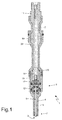
figure 1 is a longitudinal section of a fuel injector according to the present invention; -
figure 2 shows a detail offigure 1 on a larger scale; -
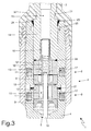
figure 3 shows a detail offigure 2 on a further larger scale; -
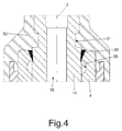
figure 4 shows a detail offigure 3 on a further larger scale; -
figure 5 shows an injection valve of the injector offigure 1 ; and -
figure 6 shows a detail offigure 5 on a larger scale. - In
Figure 1 ,number 1 indicates, as a whole, a fuel injector, which has a cylindrical symmetry around alongitudinal axis 2 and is designed to be operated so as to inject fuel through aninjection jet 3, which leads directly into an explosion chamber (not shown) of a cylinder. Theinjector 1 comprises a supportingbody 4, which has a tubular cylindrical shape with a variable cross-section along thelongitudinal axis 2 and comprises afeeding channel 5 extending along the entire length of the supportingbody 4 to feed the pressurized fuel to theinjection jet 3. - The supporting
body 4 houses anelectromagnetic actuator 6 in the area of an upper portion of its and an injection valve 7 (better visible infigure 5 ) in the area of a lower portion of its; in use, theinjection valve 7 is operated by theelectromagnetic actuator 6 so as to adjust the flow of fuel through theinjection jet 3, which is obtained in the area of theinjection valve 7. - According to
figures 2 and3 , theelectromagnetic actuator 6 comprises a pair of twin electromagnets 8 (an upper one and a lower one, respectively), which are activated together, so as to operate simultaneously. Eachelectromagnet 8, when it is excited, is designed to move, along theaxis 2, a respectivemobile armature 9 made of a ferromagnetic material from a closed position to an open position of theinjection valve 7 against the action of a single,common closing spring 10, which pushes themobile armature 9 towards the closed position of theinjection valve 7. Eachelectromagnet 8 comprises acoil 11, which is supplied with power by an electronic control unit (not shown) and is fitted on the outside relative to the supportingbody 4, as well as a fixedarmature 12 made of a ferromagnetic material, which is housed on the inside of the supportingbody 4 in a fixed position and has acentral hole 13, so as to allow fuel to flow towards theinjection jet 3. - A
metal extension 14 is partially arranged on the inside of the supportingbody 4, in a fixed position and immediately on the upper fixed armature 12 (i.e. thefixed armature 12 of the upper electromagnet 8), saidextension 14 having acentral hole 15 to allow fuel to flow towards theinjection jet 3. Theextension 14 is only partially arranged on the inside of the supportingbody 14, as an upper part of theextension 14 is arranged on the outside of the supportingbody 4; in particular, the greatest part of theextension 14 is arranged on the outside of the supportingbody 4, as you can clearly see infigure 1 . On the inside of thecentral hole 15 of theextension 14 there is fitted, in a fixed position, astriker body 16, which has a cylindrical tubular shape (if necessary, open along a generating line) to allow fuel to flow towards theinjection jet 3 and is designed to keep theclosing spring 10 compressed against the upper mobile armature 9 (i.e. against themobile armature 9 of the upper magnet 8). - Each
coil 11 is directly wound on the inside of is ownannular slot 17, which is obtained by removing material from the outer surface of the supportingbody 4. Eachcoil 11 consists of an enamelled conductor wire, which is provided with a self-bonding layer and has an axial size (namely, measured along the longitudinal axis 2) that is kept small to minimize dispersed magnetic fluxes. In the area of thecoils 11, aprotection body 18 made of a ferromagnetic material is coupled around the supportingbody 4, saidprotection body 18 having a tubular shape and being used to ensure an adequate mechanical protection of thecoils 11, to enable the closing of the streamlines of the magnetic flux generated by thecoils 11, and to the increase the mechanical resistance of the supportingbody 4 in the area of the structural weak spots unavoidably caused by the presence of theslots 17. - The
mobile armatures 9 are part of a mobile equipment, which comprises, furthermore, a shutter orplunger 19 having an upper portion integral to eachmobile armature 9 and a lower portion cooperating with a valve seat 20 (shown infigure 5 ) of theinjection valve 7 so as to adjust, in a known manner, the flow of fuel towards theinjection jet 3. - In user, when the
electromagnets 8 are not excited, eachmobile armature 9 is not attracted by itsfixed armature 12 and the elastic force of theclosing spring 10 pushes themobile armatures 9, together with theplunger 19, downwards; in this situation, theinjection valve 7 is closed. When theelectromagnets 8 are excited, eachmobile armature 9 is magnetically attracted by itsfixed armature 12 against the elastic force of theclosing spring 10 and themobile armatures 9, together with theplunger 19, move upwards so as to determine the opening of theinjection valve 7. - In order to precisely determine the upwards stroke covered by the
plunger 19, the upper mobile armature 9 (i.e. themobile armature 9 of the upper electromagnet 8) has a usable stroke that is shorter than the usable stroke of the lower mobile armature 9 (i.e. themobile armature 9 of the lower electromagnet 8). In this way, when theelectromagnets 8 are excited, it is always only the upper mobile armature 9 (i.e. themobile armature 9 of the upper electromagnet 8) that moves so as to be in contact with and strike against its fixedarmature 12, regardless of unavoidable building tolerances. In order to limit the usable stroke of the upper mobile armature 9 (i.e. themobile armature 9 of the upper electromagnet 8), the lower surface of the upper fixedarmature 12 or the upper surface of the uppermobile armature 9 are covered with a layer of a hard, non-ferromagnetic metal material, preferably chromium; in this way, the thickness of the chromium layer determines the reduction of the usable stroke of the upper mobile armature 9 (i.e. themobile armature 9 of the upper electromagnet 8). Further functions of the chromium layer are: increasing the resistance to impacts of the area and, especially, avoiding magnetic adhesion phenomena due to a direct contact between the ferromagnetic material of the upper mobile armature 9 (i.e. themobile armature 9 of the upper electromagnet 8) and the ferromagnetic material of the upper fixedarmature 12. In other words, the chromium layer defines a gap, which prevents the magnetic attraction forces caused by the residual magnetism between the upper mobile armature 9 (i.e. themobile armature 9 of the upper electromagnet 8) and the upper fixedarmature 12 from reaching values that are too high, namely greater than the elastic force generated by theclosing spring 10. - Furthermore, only the upper mobile armature 9 (i.e. the
mobile armature 9 of the upper electromagnet 8) is subjected to precision mechanical processing so as to have an adjusted outer diameter, which is substantially equal (obviously, rounded down) to the inner diameter of thefeeding channel 5; on the contrary, the lower mobile armature 9 (i.e. themobile armature 9 of the lower electromagnet 8) has an unadjusted outer diameter, which is always smaller than the inner diameter of thefeeding channel 5. In this way, only the upper mobile armature 9 (i.e. themobile armature 9 of the upper electromagnet 8) fulfils the function of upper guide of theplunger 19 to control the axial sliding of theplunger 19 along thelongitudinal axis 2. This building solution allows manufacturers to reduce manufacturing costs, as only the upper mobile armature 9 (i.e. themobile armature 9 of the upper electromagnet 8) must be subjected to precision mechanical processing, which is very expensive. - According to
figure 5 , the valve seat 20 is defined in a sealingelement 21, which is made in one piece, seals thefeeding channel 5 of the supportingbody 4 on the lower side, and is crossed by theinjection jet 3. In particular, thesealing element 21 comprises a disc-shaped plugging element 22, which seals thefeeding channel 5 of the supportingbody 4 on the lower side and is crossed by theinjection jet 3. Aguide element 23 projects from theplugging element 22, has a tubular shape, receives, on the inside, theplunger 19 so as to define a lower guide for theplunger 19 itself, and has an outer diameter that is smaller than the inner diameter of thefeeding channel 5 of the supportingbody 4 so as to define an outerannular channel 24, through which fuel under pressure can flow. - In the lower part of the
guide element 23 there are obtained feeding through hoes (not shown infigure 5 ), which lead to the valve seat 20, so as to allow fuel under pressure to flow towards the valve seat 20. The feeding holes can be staggered relative to thelongitudinal axis 2, so as not to converge towards thelongitudinal axis 2 itself and cause, in use, a vortex movement of the respective fuel flows, or the feeding holes can converge towards thelongitudinal axis 2. In the embodiment shown in the appended drawings, the feeding holes are arranged so as to be inclined at an angle of 80° (more in general, at an angle ranging from 70° to 90°) with thelongitudinal axis 2; according to a different embodiment that is not shown herein, the feeding holes form a 90° angle with thelongitudinal axis 2. - The
plunger 19 ends with a shuttinghead 25 with a substantially spherical shape, which is designed to rest against and seal the valve seat 20; alternatively, the shuttinghead 25 might have a basically cylindrical shape and have the sole striking area with a spherical shape. Furthermore, the shuttinghead 25 rests, in a sliding manner, against an inner surface of theguide element 23, so as to be guided in its movement along thelongitudinal axis 2. Theinjection jet 3 is defined by a plurality of injection through holes (not shown), which are obtained starting from aninjection chamber 26 arranged downstream of the valve seat 20. - As already mentioned above, the upper mobile armature 9 (i.e. the
mobile armature 9 of the upper electromagnet 8) has an outer diameter that is substantially identical to the inner diameter of the corresponding portion of thefeeding channel 5 of the supportingbody 4; in this way, the uppermobile armature 9 can slide relative to the supportingbody 4 along thelongitudinal axis 2, but it cannot make any movement transversely to thelongitudinal axis 2 relative to the supportingbody 4. As theplunger 19 is rigidly connected to the upper mobile armature 9 (i.e. themobile armature 9 of the upper electromagnet 8), the uppermobile armature 9 clearly fulfils the further function of upper guide of theplunger 19; as a consequence, theplunger 19 is guided by the upper mobile armature 9 (i.e. themobile armature 9 of the upper electromagnet 8) on the upper side and by theguide element 23 on the lower side. - According to
figures 2 and3 , the lower face of the upper mobile armature 9 (i.e. themobile armature 9 of the upper electromagnet 8) is connected to a hydraulic braking device, which brakes (slows down) the movement of theplunger 19 both when theplunger 19 moves from the open position to the closed position of theinjection valve 7 and when theplunger 19 moves from the closed position to the open position of theinjection valve 7. - The
plunger 19 has a stem with a cylindrical symmetry, to which the substantiallyspherical shutting head 26 is connected by means of an annular weld. In turn, the stem is connected to eachmobile armature 9 by means of an annular weld. - According to
figure 3 , the lower fixed armature 12 (i.e. the fixedarmature 12 of the lower electromagnet 8) is mechanically locked in a fixed position on the inside of the supportingbody 4 by means of a spot weld 27 (alternatively, it could also be an annular weld), which constrains the lower fixedarmature 12 to the supportingbody 4; preferably, the supportingbody 4 has a counterbore, which is made in the area of the lower fixed armature 12 (i.e. the fixedarmature 12 of the lower electromagnet 8) and houses, on the inside, theweld 27. Theweld 27 is oriented radially (namely, perpendicularly to the longitudinal axis 2) and, therefore, it develops from the outside to the inside of the supportingbody 4 along a radial direction (namely, perpendicularly to the longitudinal axis 2). Theweld 27 is never mechanically stressed in a significant manner, as it is completely on the inside of the supporting body 4 (which means that it does not have to resist to hydraulic stresses caused by the pressure of the fuel) and it is not subjected to mechanical stresses (as already mentioned above, only the uppermobile armature 9 strikes against the upper fixedarmature 12 at the end of the opening stroke of the plunger 19). - According to
figure 3 , the upper fixed armature 12 (i.e. the fixedarmature 12 of the upper electromagnet 8) is mechanically locked in a fixed position on the inside of the supportingbody 4 by means of anannular weld 28, which constrains the upper fixedarmature 12 to theextension 14. Theannular weld 28 between the upper fixed armature 12 (i.e. the fixedarmature 12 of the upper electromagnet 8) and theextension 14 is made on the outside of the supportingbody 4, namely before inserting the upper fixedarmature 12 and theextension 14, together, into the supportingbody 4; in other words, the upper fixedarmature 12 and theextension 14 are connected to one another (preassembled) by means of theannular weld 28 on the outside of the supportingbody 4 and then the upper fixedarmature 12 and theextension 14, joined to one another, are inserted, together, into the supportingbody 4. Theannular weld 28 is oriented radially (namely, perpendicularly to the longitudinal axis 2) and, therefore, it develops between the upper fixedarmature 12 and theextension 14 along a radial direction (namely, perpendicularly to the longitudinal axis 2). Theannular weld 28 has a good mechanical resistance, as it is made in ideal conditions (namely, on the outside of the supporting body 4); furthermore, theannular weld 28 is never mechanically stressed in a significant manner, as it is completely on the inside of the supporting body 4 (which means that it does not have to resist to hydraulic stresses caused by the pressure of the fuel) and works only in compression (when the uppermobile armature 9 strikes against the upper fixedarmature 12 at the end of the opening stroke of the plunger 19). - It should be pointed put that the upper fixed armature 12 (i.e. the fixed
armature 12 of the upper electromagnet 8) does not have any direct mechanical constraint to the supportingbody 4, which is means that the upper fixedarmature 12 does not have any direct mechanical connection to the supportingbody 4; as a matter of fact, the upper fixedarmature 12 is kept still on the inside of the supportingbody 4 exclusively through theannular weld 28, which mechanically constrains the fixedarmature 12 to theextension 14. - According to
figure 3 , theextension 14 is mechanically constrained to the supportingbody 4 by means of anannular weld 29, which is made in the area of an upper end of the supportingbody 4 and starting from an upper wall of the supportingbody 4. Theannular weld 29 is oriented axially (namely, parallel to the longitudinal axis 2) and, therefore, it develops between the supportingbody 4 and theextension 14 along an axial direction (namely, parallel to the longitudinal axis 2). Theannular weld 29 has a good mechanical resistance, as it is made in ideal conditions (namely, on the outside of the supporting body 4) and between materials having a high mechanical resistance (theextension 14 is not affected by the magnetic flux and, therefore, it is made of a non-ferromagnetic steel having high mechanical performances, and the supportingbody 4 is made of a steel having high mechanical performances, as well). It is important for theannular weld 29 to have a good mechanical resistance, as theannular weld 29 is mechanically stressed in a significant manner; theannular weld 29 must ensure the the upper sealing of the supportingbody 4 and, therefore, it must resist hydraulic stresses caused by the pressure of the fuel and, furthermore, theannular weld 29 must resist a shearing stress when the uppermobile armature 9 hits the upper fixedarmature 12 at the end of the opening stroke of theplunger 19. - According to
figure 4 , the supportingbody 4 has anannular recess 30, which is obtained starting from an inner surface of the supporting body 4 (namely, it faces theextension 14, which is arranged on the inside of the supporting body 4) and is arranged (immediately) below the annular weld 29 (namely, below the root of the annular weld 29). Theannular recess 30 is arranged below theannular weld 29 at a very small distance from theannular weld 29 itself; basically, the beginning of theannular recess 30 borders (i.e. is arranged flush with) the end of the annular weld 29 (i.e. the root of the annular weld 29). Alternatively, theannular recess 30 could also partially overlap the annular weld 29 (namely, the root of the annular weld 29). According to a preferred, though not binding, embodiment, theannular recess 30 has, in its cross-sectional view, a semicircular shape. Furthermore, according to a preferred, though not binding, embodiment, theannular recess 30 has an axial length that is equal to or greater than the axial length of theannular weld 29. Theannular recess 30 fulfils the function of protecting the root of theannular weld 29 from mechanical stresses; obviously, mechanical stresses cannot go through theannular recess 30, which is empty, and, therefore, they must go from the supportingbody 4 to theextension 14 moving past theannular recess 30 and spreading relatively far from the root of theannular weld 29; in other words, theannular recess 30 allows the root of theannular weld 29 to be released from tensions (in this area of theannular weld 29 there is a concentration of tensions) and to have a more uniform distribution of stresses in the weld section. To sum up, thanks to the presence of theannular recess 30, it is possible to significantly reduce the chance of formation of cracks or slits in the area of the root of the annular weld 29 (which is the most fragile area and, therefore, the one most subjected to risks in the annular weld 29) and it is also possible to allow the weld section to work in a more uniform and distributed manner. - According to
figure 4 , theextension 14 has anannular recess 31, which is obtained starting from an outer surface of theextension 14 and is arranged (immediately) above the annular weld 29 (namely, above the base of the annular weld 29). In other words, theannular recess 31 is arranged above theannular weld 29 at a very small distance from theannular weld 29 itself; generally speaking, the axial distance between theannular recess 31 and theannular weld 29 is other than zero (namely, greater than zero) and is smaller than 50% of the axial length of the annular weld 29 (it should be pointed out that the axial distance between theannular recess 31 and theannular weld 29 could also be equal to zero). According to a preferred, though not binding, embodiment, theannular recess 31 has, in its cross-sectional view, a rectangular shape with rounded vertices. Furthermore, according to a preferred, though not binding, embodiment, theannular recess 31 has an axial length that is equal to or greater than the axial length of theannular weld 29. Theannular recess 31 fulfils the function of directing the mechanical stresses transmitted between the supportingbody 4 and theextension 14 in such a way that said mechanical stresses move past theannular recess 31 and spread relatively far from the outer surface of the annular weld 29 (area of concentration of tensions), thus allowing the weld section to work in a more uniform and distributed manner. In other words, thanks to the presence of theannular recess 31, it is possible to have theannular weld 29 work better, thus substantially reducing the chance of formation of cracks or slits in the area of the outer surface of theannular weld 29. It should be pointed out that the twoannular recesses annular weld 29, they ensure a significant variation in the direction of mechanical stresses, which turn out to spread far away from both points of concentration of tensions in the weld (root and outer surface), which constitute the most fragile areas and, therefore, the ones most subjected to risks in theannular weld 29; if there were only one of theannular recesses annular weld 29, but, on the contrary, only one of them would be released from stresses to the detriment of the other one. - In order to obtain a high precision in the length of the axial stroke of the upper mobile armature 9 (i.e. the
mobile armature 9 of the upper electromagnet 8), thus compensating possible errors caused by unavoidable building tolerances, the upper fixedarmature 12, together with the extension 14 (as already mentioned above, the upper fixedarmature 12 was previously welded to theextension 14 by means of the annular weld 28), is inserted into the supportingbody 4, is caused to strike against the uppermobile armature 9 and, then, it is axially pulled away from the uppermobile armature 9 by a distance that is correlated to the desired axial stroke of the uppermobile armature 9 and permits a compensation of the shrinkages following the welding (in particular, the distance can be greater or smaller than the desired axial stroke so as to take into account the shrinkages following the welding); finally, theextension 14 is locked in the final position by means of theannular weld 29, which constrains the extension 14 (integral to the upper fixed armature 12) to the supportingbody 4. - According to a preferred embodiment shown in the appended drawings, part of the supporting
body 4 and part of theextension 14 are covered by aplastic coating 32, which is overmoulded and fulfils the function of protecting them from outer agents. - According to a preferred embodiment shown in the appended drawings, the
extension 14 is also used to connect thefuel injector 1 to a pressurized fuel feeding pipe; to this aim, the upper part of theextension 14 is threaded, so as to be connected to the pressurized fuel feeding pipe by means of screwing. - According to
figures 5 and6 , the sealingelement 21 is mechanically constrained to the supportingbody 4 by means of anannular weld 33, which is made in the area of a lower end of the supportingbody 4 and starting from a lower wall of the supportingbody 4. Theannular weld 33 is oriented axially (namely, parallel to the longitudinal axis 2) and, therefore, it develops between the supportingbody 4 and theextension 14 along an axial direction (namely, parallel to the longitudinal axis 2). Theannular weld 33 has a good mechanical resistance, as it is made in ideal conditions (namely, on the outside of the supporting body 4) and between materials having a high mechanical resistance (the sealingelement 21 and the supportingbody 4 are both made of a steel having high mechanical performances). It is important for theannular weld 33 to have a good mechanical resistance, as theannular weld 33 is mechanically stressed in a significant manner; on the one hand, theannular weld 33 must ensure the the lower sealing of the supportingbody 4 and, therefore, it must resist hydraulic stresses caused by the pressure of the fuel and, on the other hand, theannular weld 33 is arranged on the inside of a cylinder and, therefore, it is subjected to all the mechanical stresses of the combustion cycle. - According to
figures 5 and6 , the supportingbody 4 has anannular recess 34, which is obtained starting from an inner surface of the supporting body 4 (namely, it faces the sealing element 21) and is arranged (immediately) above the annular weld 33 (namely, above the root of the annular weld 33). Theannular recess 34 is arranged above theannular weld 33 at a very small distance from theannular weld 33; basically, the beginning of theannular recess 34 borders (i.e. is arranged flush with) the end of the annular weld 33 (i.e. the root of the annular weld 33). Alternatively, theannular recess 34 could also partially overlap the annular weld 33 (namely, the root of the annular weld 33). According to a preferred, though not binding, embodiment, theannular recess 34 has, in its cross-sectional view, a semicircular shape. Furthermore, according to a preferred, though not binding, embodiment, theannular recess 34 has an axial length that is equal to or smaller than three times the axial length of theannular weld 33. Theannular recess 34 fulfils the function of protecting the root of theannular weld 33 from mechanical stresses; obviously, mechanical stresses cannot go through theannular recess 34, which is empty, and, therefore, they must go from the supportingbody 4 to theextension 14 moving past theannular recess 34 and spreading relatively far from the root of theannular weld 33; in other words, theannular recess 34 allows the root of the annular weld 33 (area of concentration of tensions) to be released from tensions and to have a more uniform distribution of stresses in the weld section. To sum up, thanks to the presence of theannular recess 34, it is possible to significantly reduce the chance of formation of cracks or slits in the area of the root of the annular weld 33 (which is the most fragile area and, therefore, the one most subjected to risks in the annular weld 33) and it is also possible to allow the weld section to work in a more uniform and distributed manner. - The
fuel injector 1 described above has numerous advantages. - First of all, the
fuel injector 1 described above has a low frequency of faults due to the occurrence of cracking or other types of structural defects of the supportingbody 4 in the area of or close to theannular welds fuel injector 1 operates with a high fuel feeding pressure (above 70-80 Mpa). - Furthermore, the
fuel injector 1 described above is simple and cheap to be manufactured, as, compared to a known similar fuel injector, it has differences that can easily be produced. - It should be pointed out that the
fuel injector 1 described above can be used for the injection of any type of fuel in internal combustion engines operating according to the Otto cycle (namely, with a controlled ignition of the mixture) or in internal combustion engines operating according to the Diesel cycle (namely, with a spontaneous ignition of the mixture).
Claims (13)
- An electromagnetic fuel injector (1) comprising:an injection jet (3);an injection valve (7), which is provided with a mobile plunger (19), so as to adjust the flow of fuel through the injection jet (3);an electromagnetic actuator (6) to move the plunger (19) between a closed position and an open position of the injection valve (7) and provided with at least one first electromagnet (8) comprising a first coil (11), a first fixed armature (12), and a first mobile armature (9), which is mechanically connected to the plunger (19);a closing spring (10), which pushes the plunger (19) towards the closed position;a supporting body (4), which has a tubular shape and is provided with a central channel (5), which houses the first fixed armature (12) and the first mobile armature (9); andan extension (14), which is partially arranged on the inside of the supporting body (4) on the first fixed armature (12) and is mechanically constrained to the supporting body (4) by means of a first annular weld (29);wherein the first fixed armature (12) is mechanically locked in a fixed position on the inside of the supporting body by means of a second annular weld (28), which constrains the first fixed armature (12) to the extension (14) ;the injector (1) is characterized in that the first fixed armature (12) has no direct mechanical constraint to the supporting body (4) and is kept still on the inside of the supporting body (4) only through the second annular weld (28), which mechanically constrains the first fixed armature (12) to the extension (14).
- An injector (1) according to claim 1, wherein the first annular weld (29) is made in the area of an upper end of the supporting body (4) and starting from an upper wall of the supporting body (4).
- An injector (1) according to one of the claims 1 or 2, wherein the supporting body (4) has a first annular recess (30), which is obtained starting from an inner surface of the supporting body (4) and is arranged below the first annular weld (29).
- An injector (1) according to claim 3, wherein the beginning of the first annular recess (30) borders the end of the first annular weld (29) or the first annular recess (30) partially overlaps the first annular weld (29).
- An injector (1) according to claim 3 or 4, wherein the first annular recess (30) has, in its cross-sectional view, a semicircular shape.
- An injector (1) according to any of the claims from 1 to 5, wherein the extension (14) has a second annular recess (31), which is obtained starting from an outer surface of the extension (14) and is arranged above the first annular weld (29).
- An injector (1) according to claim 6, wherein the second annular recess (31) is arranged close to the first annular weld (29).
- An injector (1) according to claim 6 or 7, wherein the second annular recess (31) has, in its cross-sectional view, a rectangular shape.
- An injector (1) according to any of the claims from 1 to 8, wherein the extension (14) has a central hole (15), which allows fuel to flow towards the injection jet (3) and partially houses the closing spring (10); and
on the inside of the central hole (15) of the extension (14) there is fitted, in a fixed position, a striker body (16), which has a cylindrical tubular shape and is designed to keep the closing spring (10) compressed against the first mobile armature (9). - An injector (1) according to any of the claims from 1 to 9, wherein:the electromagnetic actuator (6) is provided with a second electromagnet (8), which is arranged below the first electromagnet (8) and comprises a second coil (11), a second fixed armature (12), and a second mobile armature (9), which is mechanically connected to the plunger (19);the first mobile armature (9) has a usable stroke that is shorter than the usable stroke of the second mobile armature (9); andthe second fixed armature (12) is mechanically locked in a fixed position on the inside of the supporting body (4) by means of a third weld (27), which directly constrains the second fixed armature (12) to the supporting body (4) and develops from the outside to the inside of the supporting body (4) along a radial direction.
- An injector (1) according to claim 10, wherein the supporting body (4) has a spot-face, which is obtained in the area of the second fixed armature (12), so that the third weld (27) can be made therein.
- An injector (1) according to any of the claims from 1 to 11, wherein the extension (14) has an upper threaded part for the connection to a feeding pipe for fuel under pressure.
- A method to manufacture a fuel injector (1) comprising:an injection jet (3);an injection valve (7), which is provided with a mobile plunger (19), so as to adjust the flow of fuel through the injection jet (3);an electromagnetic actuator (6) to move the plunger (19) between a closed position and an open position of the injection valve (7) and provided with at least one electromagnet (8) comprising a coil (11), a fixed armature (12), and a mobile armature (9), which is mechanically connected to the plunger (19);a closing spring (10), which pushes the plunger (19) towards the closed position;a supporting body (4), which has a tubular shape and is provided with a central channel (5), which houses the fixed armature (12) and the mobile armature (9); andan extension (14), which is partially arranged on the inside of the supporting body (4) on the fixed armature (12) and is mechanically constrained to the supporting body (4) by means of a first annular weld (29);wherein the first fixed armature (12) is mechanically locked in a fixed position on the inside of the supporting body by means of a second annular weld (28), which constrains the first fixed armature (12) to the elongating rod (14); andwherein the first fixed armature (12) has no direct mechanical constraint to the supporting body (4) and is kept still on the inside of the supporting body (4) only through the second annular weld (28), which mechanically constrains the first fixed armature (12) to the elongating rod (14).the manufacturing method is characterized in that it comprises the steps of:constraining the fixed armature (12) and the extension (14) to one another, by means of the second annular weld (28), on the outside of the supporting body (4), so as to pre-assemble the first fixed armature (12) and the extension (14) on the outside of the supporting body (4);inserting the fixed armature (12) and the extension (14) into the supporting body (4);causing the fixed armature (12) and the extension (14) to strike against the mobile rod (9);pulling the fixed armature (12) and the extension (14) away by a distance that is correlated to the desired axial stroke of the mobile armature (9), so as to determine the final position of the extension (14) before making the first annular weld (29); andconstraining the extension (14) to the supporting body (4) by means of the first annular weld (29).
Applications Claiming Priority (1)
| Application Number | Priority Date | Filing Date | Title |
|---|---|---|---|
| ITBO2015A000235A ITBO20150235A1 (en) | 2015-05-05 | 2015-05-05 | ELECTROMAGNETIC FUEL INJECTOR WITH WELDING OPTIMIZATION |
Publications (2)
| Publication Number | Publication Date |
|---|---|
| EP3091218A1 true EP3091218A1 (en) | 2016-11-09 |
| EP3091218B1 EP3091218B1 (en) | 2019-04-24 |
Family
ID=53836633
Family Applications (1)
| Application Number | Title | Priority Date | Filing Date |
|---|---|---|---|
| EP16168518.5A Not-in-force EP3091218B1 (en) | 2015-05-05 | 2016-05-05 | Electromagnetic fuel injector with optimization of the welds |
Country Status (3)
| Country | Link |
|---|---|
| EP (1) | EP3091218B1 (en) |
| JP (1) | JP6829004B2 (en) |
| IT (1) | ITBO20150235A1 (en) |
Cited By (3)
| Publication number | Priority date | Publication date | Assignee | Title |
|---|---|---|---|---|
| CN116213935A (en) * | 2022-12-29 | 2023-06-06 | 广西松浦电子科技有限公司 | High-speed electromagnetic valve welding process |
| EP4491865A1 (en) * | 2023-07-10 | 2025-01-15 | Marelli Europe S.p.A. | Electromagnetic fuel injector |
| EP4491866A1 (en) * | 2023-07-10 | 2025-01-15 | Marelli Europe S.p.A. | Electromagnetic fuel injector with two independent coils and related control method |
Citations (5)
| Publication number | Priority date | Publication date | Assignee | Title |
|---|---|---|---|---|
| US6244526B1 (en) | 1996-09-24 | 2001-06-12 | Robert Bosch Gmbh | Fuel injection valve |
| WO2001057390A1 (en) * | 2000-02-04 | 2001-08-09 | Robert Bosch Gmbh | Fuel injection valve and method for operating the same |
| EP1229239A2 (en) * | 2001-02-02 | 2002-08-07 | Siemens VDO Automotive Corporation | Combined filter and adjuster for a fuel injector |
| US20040050977A1 (en) * | 2001-07-27 | 2004-03-18 | Franz Rieger | Fuel injection valve |
| EP1619384A2 (en) | 2004-07-23 | 2006-01-25 | Magneti Marelli Powertrain S.p.A. | Fuel injector provided with a high flexibility plunger |
Family Cites Families (7)
| Publication number | Priority date | Publication date | Assignee | Title |
|---|---|---|---|---|
| JP2006307831A (en) * | 2005-03-29 | 2006-11-09 | Denso Corp | Fuel injection valve |
| JP4757073B2 (en) * | 2006-03-29 | 2011-08-24 | 株式会社ケーヒン | Fuel injection valve |
| JP5012603B2 (en) * | 2008-03-19 | 2012-08-29 | 株式会社デンソー | Fuel injection valve and manufacturing method thereof |
| JP5509901B2 (en) * | 2010-02-12 | 2014-06-04 | 株式会社デンソー | Fuel injection valve |
| JP2014009653A (en) * | 2012-07-02 | 2014-01-20 | Mitsubishi Electric Corp | Fuel injection valve |
| ITBO20130169A1 (en) * | 2013-04-17 | 2014-10-18 | Magneti Marelli Spa | ELECTROMAGNETIC FUEL INJECTOR WITH BRAKING DEVICE |
| JP6208053B2 (en) * | 2014-03-10 | 2017-10-04 | 三菱電機株式会社 | Fuel injection valve |
-
2015
- 2015-05-05 IT ITBO2015A000235A patent/ITBO20150235A1/en unknown
-
2016
- 2016-05-02 JP JP2016092596A patent/JP6829004B2/en not_active Expired - Fee Related
- 2016-05-05 EP EP16168518.5A patent/EP3091218B1/en not_active Not-in-force
Patent Citations (5)
| Publication number | Priority date | Publication date | Assignee | Title |
|---|---|---|---|---|
| US6244526B1 (en) | 1996-09-24 | 2001-06-12 | Robert Bosch Gmbh | Fuel injection valve |
| WO2001057390A1 (en) * | 2000-02-04 | 2001-08-09 | Robert Bosch Gmbh | Fuel injection valve and method for operating the same |
| EP1229239A2 (en) * | 2001-02-02 | 2002-08-07 | Siemens VDO Automotive Corporation | Combined filter and adjuster for a fuel injector |
| US20040050977A1 (en) * | 2001-07-27 | 2004-03-18 | Franz Rieger | Fuel injection valve |
| EP1619384A2 (en) | 2004-07-23 | 2006-01-25 | Magneti Marelli Powertrain S.p.A. | Fuel injector provided with a high flexibility plunger |
Cited By (3)
| Publication number | Priority date | Publication date | Assignee | Title |
|---|---|---|---|---|
| CN116213935A (en) * | 2022-12-29 | 2023-06-06 | 广西松浦电子科技有限公司 | High-speed electromagnetic valve welding process |
| EP4491865A1 (en) * | 2023-07-10 | 2025-01-15 | Marelli Europe S.p.A. | Electromagnetic fuel injector |
| EP4491866A1 (en) * | 2023-07-10 | 2025-01-15 | Marelli Europe S.p.A. | Electromagnetic fuel injector with two independent coils and related control method |
Also Published As
| Publication number | Publication date |
|---|---|
| JP6829004B2 (en) | 2021-02-10 |
| ITBO20150235A1 (en) | 2016-11-05 |
| EP3091218B1 (en) | 2019-04-24 |
| JP2016211566A (en) | 2016-12-15 |
Similar Documents
| Publication | Publication Date | Title |
|---|---|---|
| EP3091219B1 (en) | Electromagnetic fuel injector with an annular recess arranged in the area of the weld of an extension | |
| EP1878908B1 (en) | Electromagnetic fuel injection valve | |
| EP3091218B1 (en) | Electromagnetic fuel injector with optimization of the welds | |
| US5645226A (en) | Solenoid motion initiator | |
| EP2792877B1 (en) | Electromagnetic fuel injector with braking device | |
| CN104033300B (en) | A kind of Fuelinjection nozzle | |
| KR101857463B1 (en) | Valve assembly for an injection valve, injection valve and method for assembling a valve assembly of an injection valve | |
| CN101910609B (en) | Electromagnetically actuated valve | |
| CN1776214B (en) | Fuel Injector with Electromagnetic Actuation of the Plunger | |
| CN107091362B (en) | Coaxial double-electromagnetic fuel gas injection valve with adjustable cross-sectional flow area | |
| CN107091172A (en) | A kind of interior guiding fuel gas injection valve of through type axial admission | |
| CN103233838A (en) | Electronic control gasoline injector and manufacturing method thereof | |
| EP3109455B1 (en) | Fuel injection rate modulation by magnetostrictive actuator and fluidomechanical coupler | |
| US20130206872A1 (en) | Fuel injector | |
| US20150136879A1 (en) | Fuel injector | |
| CN101484678A (en) | Method for injecting fuel by means of a fuel injection system | |
| EP2466109A1 (en) | Valve assembly for an injection valve and injection valve | |
| KR102491213B1 (en) | Coated moldings and methods for producing coated moldings | |
| WO2019115824A1 (en) | Electromagnetic sleeve for hydrogen valve | |
| AU2005287878B2 (en) | Gas injector | |
| EP2703633A1 (en) | Valve assembly for an injection valve and injection valve | |
| CZ295158B6 (en) | fuel injection valve | |
| CN119222079A (en) | A dual electromagnetic control injector | |
| EP2363592A1 (en) | Injection valve | |
| KR20180063896A (en) | Fuel injection valve with welding ring and method for manufacturing same |
Legal Events
| Date | Code | Title | Description |
|---|---|---|---|
| PUAI | Public reference made under article 153(3) epc to a published international application that has entered the european phase |
Free format text: ORIGINAL CODE: 0009012 |
|
| AK | Designated contracting states |
Kind code of ref document: A1 Designated state(s): AL AT BE BG CH CY CZ DE DK EE ES FI FR GB GR HR HU IE IS IT LI LT LU LV MC MK MT NL NO PL PT RO RS SE SI SK SM TR |
|
| AX | Request for extension of the european patent |
Extension state: BA ME |
|
| STAA | Information on the status of an ep patent application or granted ep patent |
Free format text: STATUS: REQUEST FOR EXAMINATION WAS MADE |
|
| 17P | Request for examination filed |
Effective date: 20170508 |
|
| GRAP | Despatch of communication of intention to grant a patent |
Free format text: ORIGINAL CODE: EPIDOSNIGR1 |
|
| STAA | Information on the status of an ep patent application or granted ep patent |
Free format text: STATUS: GRANT OF PATENT IS INTENDED |
|
| INTG | Intention to grant announced |
Effective date: 20181114 |
|
| RIN1 | Information on inventor provided before grant (corrected) |
Inventor name: VEZZANI, ENRICO Inventor name: PETRECCHIA, STEFANO |
|
| GRAS | Grant fee paid |
Free format text: ORIGINAL CODE: EPIDOSNIGR3 |
|
| GRAA | (expected) grant |
Free format text: ORIGINAL CODE: 0009210 |
|
| STAA | Information on the status of an ep patent application or granted ep patent |
Free format text: STATUS: THE PATENT HAS BEEN GRANTED |
|
| AK | Designated contracting states |
Kind code of ref document: B1 Designated state(s): AL AT BE BG CH CY CZ DE DK EE ES FI FR GB GR HR HU IE IS IT LI LT LU LV MC MK MT NL NO PL PT RO RS SE SI SK SM TR |
|
| REG | Reference to a national code |
Ref country code: GB Ref legal event code: FG4D |
|
| REG | Reference to a national code |
Ref country code: CH Ref legal event code: EP |
|
| REG | Reference to a national code |
Ref country code: AT Ref legal event code: REF Ref document number: 1124455 Country of ref document: AT Kind code of ref document: T Effective date: 20190515 Ref country code: IE Ref legal event code: FG4D |
|
| REG | Reference to a national code |
Ref country code: DE Ref legal event code: R096 Ref document number: 602016012742 Country of ref document: DE |
|
| REG | Reference to a national code |
Ref country code: NL Ref legal event code: MP Effective date: 20190424 |
|
| REG | Reference to a national code |
Ref country code: LT Ref legal event code: MG4D |
|
| PG25 | Lapsed in a contracting state [announced via postgrant information from national office to epo] |
Ref country code: NL Free format text: LAPSE BECAUSE OF FAILURE TO SUBMIT A TRANSLATION OF THE DESCRIPTION OR TO PAY THE FEE WITHIN THE PRESCRIBED TIME-LIMIT Effective date: 20190424 |
|
| PG25 | Lapsed in a contracting state [announced via postgrant information from national office to epo] |
Ref country code: NO Free format text: LAPSE BECAUSE OF FAILURE TO SUBMIT A TRANSLATION OF THE DESCRIPTION OR TO PAY THE FEE WITHIN THE PRESCRIBED TIME-LIMIT Effective date: 20190724 Ref country code: SE Free format text: LAPSE BECAUSE OF FAILURE TO SUBMIT A TRANSLATION OF THE DESCRIPTION OR TO PAY THE FEE WITHIN THE PRESCRIBED TIME-LIMIT Effective date: 20190424 Ref country code: FI Free format text: LAPSE BECAUSE OF FAILURE TO SUBMIT A TRANSLATION OF THE DESCRIPTION OR TO PAY THE FEE WITHIN THE PRESCRIBED TIME-LIMIT Effective date: 20190424 Ref country code: AL Free format text: LAPSE BECAUSE OF FAILURE TO SUBMIT A TRANSLATION OF THE DESCRIPTION OR TO PAY THE FEE WITHIN THE PRESCRIBED TIME-LIMIT Effective date: 20190424 Ref country code: PT Free format text: LAPSE BECAUSE OF FAILURE TO SUBMIT A TRANSLATION OF THE DESCRIPTION OR TO PAY THE FEE WITHIN THE PRESCRIBED TIME-LIMIT Effective date: 20190824 Ref country code: HR Free format text: LAPSE BECAUSE OF FAILURE TO SUBMIT A TRANSLATION OF THE DESCRIPTION OR TO PAY THE FEE WITHIN THE PRESCRIBED TIME-LIMIT Effective date: 20190424 Ref country code: LT Free format text: LAPSE BECAUSE OF FAILURE TO SUBMIT A TRANSLATION OF THE DESCRIPTION OR TO PAY THE FEE WITHIN THE PRESCRIBED TIME-LIMIT Effective date: 20190424 Ref country code: ES Free format text: LAPSE BECAUSE OF FAILURE TO SUBMIT A TRANSLATION OF THE DESCRIPTION OR TO PAY THE FEE WITHIN THE PRESCRIBED TIME-LIMIT Effective date: 20190424 |
|
| PG25 | Lapsed in a contracting state [announced via postgrant information from national office to epo] |
Ref country code: BG Free format text: LAPSE BECAUSE OF FAILURE TO SUBMIT A TRANSLATION OF THE DESCRIPTION OR TO PAY THE FEE WITHIN THE PRESCRIBED TIME-LIMIT Effective date: 20190724 Ref country code: RS Free format text: LAPSE BECAUSE OF FAILURE TO SUBMIT A TRANSLATION OF THE DESCRIPTION OR TO PAY THE FEE WITHIN THE PRESCRIBED TIME-LIMIT Effective date: 20190424 Ref country code: PL Free format text: LAPSE BECAUSE OF FAILURE TO SUBMIT A TRANSLATION OF THE DESCRIPTION OR TO PAY THE FEE WITHIN THE PRESCRIBED TIME-LIMIT Effective date: 20190424 Ref country code: GR Free format text: LAPSE BECAUSE OF FAILURE TO SUBMIT A TRANSLATION OF THE DESCRIPTION OR TO PAY THE FEE WITHIN THE PRESCRIBED TIME-LIMIT Effective date: 20190725 Ref country code: LV Free format text: LAPSE BECAUSE OF FAILURE TO SUBMIT A TRANSLATION OF THE DESCRIPTION OR TO PAY THE FEE WITHIN THE PRESCRIBED TIME-LIMIT Effective date: 20190424 |
|
| REG | Reference to a national code |
Ref country code: AT Ref legal event code: MK05 Ref document number: 1124455 Country of ref document: AT Kind code of ref document: T Effective date: 20190424 |
|
| REG | Reference to a national code |
Ref country code: CH Ref legal event code: PL |
|
| PG25 | Lapsed in a contracting state [announced via postgrant information from national office to epo] |
Ref country code: IS Free format text: LAPSE BECAUSE OF FAILURE TO SUBMIT A TRANSLATION OF THE DESCRIPTION OR TO PAY THE FEE WITHIN THE PRESCRIBED TIME-LIMIT Effective date: 20190824 |
|
| REG | Reference to a national code |
Ref country code: DE Ref legal event code: R097 Ref document number: 602016012742 Country of ref document: DE |
|
| PG25 | Lapsed in a contracting state [announced via postgrant information from national office to epo] |
Ref country code: SK Free format text: LAPSE BECAUSE OF FAILURE TO SUBMIT A TRANSLATION OF THE DESCRIPTION OR TO PAY THE FEE WITHIN THE PRESCRIBED TIME-LIMIT Effective date: 20190424 Ref country code: CH Free format text: LAPSE BECAUSE OF NON-PAYMENT OF DUE FEES Effective date: 20190531 Ref country code: RO Free format text: LAPSE BECAUSE OF FAILURE TO SUBMIT A TRANSLATION OF THE DESCRIPTION OR TO PAY THE FEE WITHIN THE PRESCRIBED TIME-LIMIT Effective date: 20190424 Ref country code: LI Free format text: LAPSE BECAUSE OF NON-PAYMENT OF DUE FEES Effective date: 20190531 Ref country code: CZ Free format text: LAPSE BECAUSE OF FAILURE TO SUBMIT A TRANSLATION OF THE DESCRIPTION OR TO PAY THE FEE WITHIN THE PRESCRIBED TIME-LIMIT Effective date: 20190424 Ref country code: DK Free format text: LAPSE BECAUSE OF FAILURE TO SUBMIT A TRANSLATION OF THE DESCRIPTION OR TO PAY THE FEE WITHIN THE PRESCRIBED TIME-LIMIT Effective date: 20190424 Ref country code: EE Free format text: LAPSE BECAUSE OF FAILURE TO SUBMIT A TRANSLATION OF THE DESCRIPTION OR TO PAY THE FEE WITHIN THE PRESCRIBED TIME-LIMIT Effective date: 20190424 Ref country code: AT Free format text: LAPSE BECAUSE OF FAILURE TO SUBMIT A TRANSLATION OF THE DESCRIPTION OR TO PAY THE FEE WITHIN THE PRESCRIBED TIME-LIMIT Effective date: 20190424 Ref country code: MC Free format text: LAPSE BECAUSE OF FAILURE TO SUBMIT A TRANSLATION OF THE DESCRIPTION OR TO PAY THE FEE WITHIN THE PRESCRIBED TIME-LIMIT Effective date: 20190424 |
|
| REG | Reference to a national code |
Ref country code: BE Ref legal event code: MM Effective date: 20190531 |
|
| PG25 | Lapsed in a contracting state [announced via postgrant information from national office to epo] |
Ref country code: SM Free format text: LAPSE BECAUSE OF FAILURE TO SUBMIT A TRANSLATION OF THE DESCRIPTION OR TO PAY THE FEE WITHIN THE PRESCRIBED TIME-LIMIT Effective date: 20190424 Ref country code: LU Free format text: LAPSE BECAUSE OF NON-PAYMENT OF DUE FEES Effective date: 20190505 |
|
| PLBE | No opposition filed within time limit |
Free format text: ORIGINAL CODE: 0009261 |
|
| STAA | Information on the status of an ep patent application or granted ep patent |
Free format text: STATUS: NO OPPOSITION FILED WITHIN TIME LIMIT |
|
| PG25 | Lapsed in a contracting state [announced via postgrant information from national office to epo] |
Ref country code: TR Free format text: LAPSE BECAUSE OF FAILURE TO SUBMIT A TRANSLATION OF THE DESCRIPTION OR TO PAY THE FEE WITHIN THE PRESCRIBED TIME-LIMIT Effective date: 20190424 |
|
| 26N | No opposition filed |
Effective date: 20200127 |
|
| PG25 | Lapsed in a contracting state [announced via postgrant information from national office to epo] |
Ref country code: IE Free format text: LAPSE BECAUSE OF NON-PAYMENT OF DUE FEES Effective date: 20190505 |
|
| PG25 | Lapsed in a contracting state [announced via postgrant information from national office to epo] |
Ref country code: SI Free format text: LAPSE BECAUSE OF FAILURE TO SUBMIT A TRANSLATION OF THE DESCRIPTION OR TO PAY THE FEE WITHIN THE PRESCRIBED TIME-LIMIT Effective date: 20190424 Ref country code: BE Free format text: LAPSE BECAUSE OF NON-PAYMENT OF DUE FEES Effective date: 20190531 |
|
| PGFP | Annual fee paid to national office [announced via postgrant information from national office to epo] |
Ref country code: DE Payment date: 20200421 Year of fee payment: 5 Ref country code: FR Payment date: 20200422 Year of fee payment: 5 |
|
| PGFP | Annual fee paid to national office [announced via postgrant information from national office to epo] |
Ref country code: IT Payment date: 20200421 Year of fee payment: 5 |
|
| GBPC | Gb: european patent ceased through non-payment of renewal fee |
Effective date: 20200505 |
|
| PG25 | Lapsed in a contracting state [announced via postgrant information from national office to epo] |
Ref country code: GB Free format text: LAPSE BECAUSE OF NON-PAYMENT OF DUE FEES Effective date: 20200505 |
|
| PG25 | Lapsed in a contracting state [announced via postgrant information from national office to epo] |
Ref country code: CY Free format text: LAPSE BECAUSE OF FAILURE TO SUBMIT A TRANSLATION OF THE DESCRIPTION OR TO PAY THE FEE WITHIN THE PRESCRIBED TIME-LIMIT Effective date: 20190424 |
|
| PG25 | Lapsed in a contracting state [announced via postgrant information from national office to epo] |
Ref country code: HU Free format text: LAPSE BECAUSE OF FAILURE TO SUBMIT A TRANSLATION OF THE DESCRIPTION OR TO PAY THE FEE WITHIN THE PRESCRIBED TIME-LIMIT; INVALID AB INITIO Effective date: 20160505 Ref country code: MT Free format text: LAPSE BECAUSE OF FAILURE TO SUBMIT A TRANSLATION OF THE DESCRIPTION OR TO PAY THE FEE WITHIN THE PRESCRIBED TIME-LIMIT Effective date: 20190424 |
|
| REG | Reference to a national code |
Ref country code: DE Ref legal event code: R119 Ref document number: 602016012742 Country of ref document: DE |
|
| PG25 | Lapsed in a contracting state [announced via postgrant information from national office to epo] |
Ref country code: DE Free format text: LAPSE BECAUSE OF NON-PAYMENT OF DUE FEES Effective date: 20211201 |
|
| PG25 | Lapsed in a contracting state [announced via postgrant information from national office to epo] |
Ref country code: FR Free format text: LAPSE BECAUSE OF NON-PAYMENT OF DUE FEES Effective date: 20210531 |
|
| PG25 | Lapsed in a contracting state [announced via postgrant information from national office to epo] |
Ref country code: MK Free format text: LAPSE BECAUSE OF FAILURE TO SUBMIT A TRANSLATION OF THE DESCRIPTION OR TO PAY THE FEE WITHIN THE PRESCRIBED TIME-LIMIT Effective date: 20190424 |
|
| PG25 | Lapsed in a contracting state [announced via postgrant information from national office to epo] |
Ref country code: IT Free format text: LAPSE BECAUSE OF NON-PAYMENT OF DUE FEES Effective date: 20200505 |
|
| PG25 | Lapsed in a contracting state [announced via postgrant information from national office to epo] |
Ref country code: IT Free format text: LAPSE BECAUSE OF NON-PAYMENT OF DUE FEES Effective date: 20210505 |