EP1619384A2 - Fuel injector provided with a high flexibility plunger - Google Patents
Fuel injector provided with a high flexibility plunger Download PDFInfo
- Publication number
- EP1619384A2 EP1619384A2 EP05106781A EP05106781A EP1619384A2 EP 1619384 A2 EP1619384 A2 EP 1619384A2 EP 05106781 A EP05106781 A EP 05106781A EP 05106781 A EP05106781 A EP 05106781A EP 1619384 A2 EP1619384 A2 EP 1619384A2
- Authority
- EP
- European Patent Office
- Prior art keywords
- injector
- plunger
- rod
- fuel
- injection
- Prior art date
- Legal status (The legal status is an assumption and is not a legal conclusion. Google has not performed a legal analysis and makes no representation as to the accuracy of the status listed.)
- Granted
Links
- 239000000446 fuel Substances 0.000 title claims abstract description 33
- 238000002347 injection Methods 0.000 claims abstract description 40
- 239000007924 injection Substances 0.000 claims abstract description 40
- 238000007789 sealing Methods 0.000 claims abstract description 27
- ZZUFCTLCJUWOSV-UHFFFAOYSA-N furosemide Chemical compound C1=C(Cl)C(S(=O)(=O)N)=CC(C(O)=O)=C1NCC1=CC=CO1 ZZUFCTLCJUWOSV-UHFFFAOYSA-N 0.000 claims description 11
- 230000005291 magnetic effect Effects 0.000 claims description 10
- 230000002093 peripheral effect Effects 0.000 claims description 3
- 230000035882 stress Effects 0.000 description 10
- 230000005540 biological transmission Effects 0.000 description 4
- 239000000463 material Substances 0.000 description 4
- 238000013459 approach Methods 0.000 description 3
- 230000008878 coupling Effects 0.000 description 3
- 238000010168 coupling process Methods 0.000 description 3
- 238000005859 coupling reaction Methods 0.000 description 3
- 230000009429 distress Effects 0.000 description 2
- 238000004458 analytical method Methods 0.000 description 1
- 239000000470 constituent Substances 0.000 description 1
- 238000013016 damping Methods 0.000 description 1
- 230000000694 effects Effects 0.000 description 1
- 230000005611 electricity Effects 0.000 description 1
- 238000004880 explosion Methods 0.000 description 1
- 239000003302 ferromagnetic material Substances 0.000 description 1
- 238000003754 machining Methods 0.000 description 1
- 230000000284 resting effect Effects 0.000 description 1
Images


Classifications
-
- F—MECHANICAL ENGINEERING; LIGHTING; HEATING; WEAPONS; BLASTING
- F02—COMBUSTION ENGINES; HOT-GAS OR COMBUSTION-PRODUCT ENGINE PLANTS
- F02M—SUPPLYING COMBUSTION ENGINES IN GENERAL WITH COMBUSTIBLE MIXTURES OR CONSTITUENTS THEREOF
- F02M61/00—Fuel-injectors not provided for in groups F02M39/00 - F02M57/00 or F02M67/00
- F02M61/16—Details not provided for in, or of interest apart from, the apparatus of groups F02M61/02 - F02M61/14
-
- F—MECHANICAL ENGINEERING; LIGHTING; HEATING; WEAPONS; BLASTING
- F02—COMBUSTION ENGINES; HOT-GAS OR COMBUSTION-PRODUCT ENGINE PLANTS
- F02M—SUPPLYING COMBUSTION ENGINES IN GENERAL WITH COMBUSTIBLE MIXTURES OR CONSTITUENTS THEREOF
- F02M51/00—Fuel-injection apparatus characterised by being operated electrically
- F02M51/06—Injectors peculiar thereto with means directly operating the valve needle
- F02M51/061—Injectors peculiar thereto with means directly operating the valve needle using electromagnetic operating means
- F02M51/0625—Injectors peculiar thereto with means directly operating the valve needle using electromagnetic operating means characterised by arrangement of mobile armatures
- F02M51/0664—Injectors peculiar thereto with means directly operating the valve needle using electromagnetic operating means characterised by arrangement of mobile armatures having a cylindrically or partly cylindrically shaped armature, e.g. entering the winding; having a plate-shaped or undulated armature entering the winding
- F02M51/0671—Injectors peculiar thereto with means directly operating the valve needle using electromagnetic operating means characterised by arrangement of mobile armatures having a cylindrically or partly cylindrically shaped armature, e.g. entering the winding; having a plate-shaped or undulated armature entering the winding the armature having an elongated valve body attached thereto
-
- F—MECHANICAL ENGINEERING; LIGHTING; HEATING; WEAPONS; BLASTING
- F02—COMBUSTION ENGINES; HOT-GAS OR COMBUSTION-PRODUCT ENGINE PLANTS
- F02M—SUPPLYING COMBUSTION ENGINES IN GENERAL WITH COMBUSTIBLE MIXTURES OR CONSTITUENTS THEREOF
- F02M61/00—Fuel-injectors not provided for in groups F02M39/00 - F02M57/00 or F02M67/00
- F02M61/04—Fuel-injectors not provided for in groups F02M39/00 - F02M57/00 or F02M67/00 having valves, e.g. having a plurality of valves in series
- F02M61/10—Other injectors with elongated valve bodies, i.e. of needle-valve type
-
- F—MECHANICAL ENGINEERING; LIGHTING; HEATING; WEAPONS; BLASTING
- F02—COMBUSTION ENGINES; HOT-GAS OR COMBUSTION-PRODUCT ENGINE PLANTS
- F02M—SUPPLYING COMBUSTION ENGINES IN GENERAL WITH COMBUSTIBLE MIXTURES OR CONSTITUENTS THEREOF
- F02M61/00—Fuel-injectors not provided for in groups F02M39/00 - F02M57/00 or F02M67/00
- F02M61/16—Details not provided for in, or of interest apart from, the apparatus of groups F02M61/02 - F02M61/14
- F02M61/166—Selection of particular materials
Definitions
- the present invention relates to a fuel injector.
- An electromagnetic fuel injector normally comprises a cylindrical tubular body with a central channel which performs the function of a fuel duct and ends with an injection jet controlled by an injection valve operated by an electromagnetic actuator; in particular, the injection valve is provided with a plunger, which is rigidly connected to a mobile armature of the electromagnetic actuator so as to be displaced by the action of the electromagnetic actuator between a closed position and an open position of the injection jet against the action of a spring which tends to hold the plunger in the closed position.
- the dimensions and positioning of the plunger, of the valve seat and of the armature must be very accurate. Indeed, if structural tolerances are relatively large, when the armature strikes against a fixed armature of the electromagnet, transverse forces may arise which are transmitted to the plunger and are in part dissipated at the level of the coupling between the end portion of the plunger and the guide portion of the valve seat; it has been observed experimentally that if such forces exceed a certain value, localised wear phenomena may occur on the plunger and/or the guide portion of the valve seat with a consequent reduction in the service life of the injector.
- the plunger and the guide parts of the plunger must be manufactured to very fine tolerances which accordingly involves complex and costly processing.
- the object of the present invention is to provide a fuel injector which does not exhibit the above-stated disadvantages and, in particular, is simple and economic to produce.
- the present invention provides a fuel injector as specified in the attached claims.
- FIG 1 denotes the overall fuel injector, which exhibits a substantially cylindrical symmetry around a longitudinal axis 2 and is capable of being operated to inject fuel from an injection jet 3 which opens directly into an explosion chamber (not shown) of a cylinder.
- the injector 1 comprises a supporting body 4, which has a tubular cylindrical shape of variable cross-section along the longitudinal axis 2 and comprises a supply channel 5 extending along the entire length of said supporting body 4 to supply the pressurised fuel to the injection jet 3.
- the supporting body 4 accommodates an electromagnetic actuator 6 at the level of an upper portion thereof and an injection valve 7 at the level of a lower portion thereof; in service, the injection valve 7 is actuated by the electromagnetic actuator 6 to control the flow of fuel through the injection jet 3, which is provided at the level of said injection valve 7.
- the electromagnetic actuator 6 comprises an electromagnet 8, which is accommodated in fixed position within the supporting body 4 and which, when energised, is capable of displacing a mobile armature 9 of ferromagnetic material along the axis 2 from a closed position to an open position of the injection valve 7 against the action of a spring 10 which tends to hold the mobile armature 9 in the closed position of the injection valve 7.
- the electromagnet 8 comprises a coil 11, which is supplied with electricity by an electronic control unit (not shown) and is accommodated outside the supporting body 4, and a fixed magnetic armature 12, which is accommodated inside the supporting body 4 and has a central hole 13 to allow the fuel to flow towards the injection jet 3.
- an abutment member 14 is driven into a fixed position, which abutment member is of a tubular cylindrical shape (optionally open along a generating line) to allow the fuel to flow towards the injection jet 3 and is capable of holding the spring 10 in a compressed state against the mobile armature 9.
- the mobile armature 9 is part of a mobile assembly which moreover comprises a poppet or plunger 15 having an upper portion integral with the mobile armature 9 and a lower portion which cooperates with a valve seat 16 (shown in Figure 2) of the injection valve 7 to control the flow of fuel through the injection jet 3 in known manner.
- a poppet or plunger 15 having an upper portion integral with the mobile armature 9 and a lower portion which cooperates with a valve seat 16 (shown in Figure 2) of the injection valve 7 to control the flow of fuel through the injection jet 3 in known manner.
- the valve seat 16 is defined by a sealing member 17, which is disc-shaped, seals the bottom of the supply channel 5 of the supporting body 4, and is passed through by the injection jet 3.
- a guide member 18 rises up from the discoid sealing member 17, which guide member is tubular in shape, receives within it the plunger 15 to define a lower guide for said plunger 15 and has an external diameter smaller than the internal diameter of the supply channel 5 of the supporting body 4, so as to define an external annular channel 19 through which the pressurised fuel can flow.
- the guide member 18 has an external diameter which is equal to the internal diameter of the supply channel 5 and has flattened portions on the outside so as to create passages for the fuel.
- through-holes 20 In the lower part of the guide member 18, there are provided four through-holes 20 (only two of which are shown in Figure 2), which are arranged perpendicularly to the longitudinal axis 2 and open into the valve seat 16 to allow the pressurised fuel to flow towards said valve seat 16.
- the through-holes 20 may be arranged offset relative to the longitudinal axis 2 such that they do not converge towards said longitudinal axis 2 and, in service, they impart a swirling flow to the respective streams of fuel.
- the plunger 15 ends in a sealing head 21, substantially spherical in shape, which is capable of resting in sealing manner against the valve seat 16. Furthermore, the sealing head 21 rests so as to slide on a cylindrical internal surface 22 of the guide member 18, so that it will be guided as it moves along the longitudinal axis 2.
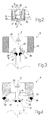
- the mobile armature 9 is a monolithic body and comprises an annular member 23 and a discoid member 24, which closes the bottom of the annular member 23 and has a central through-hole 25 capable of receiving an upper portion of the plunger 15 and a plurality of peripheral through-holes 26 (only two of which are shown in Figure 3) capable of allowing the fuel to flow towards the injection jet 3.
- a central portion of the discoid member 24 is suitably shaped to receive a lower end of the spring 10 and hold it in position.
- the plunger 15 is preferably made integral with the discoid member 24 of the mobile armature 9 by means of an annular weld 27.
- Figure 4 shows an alternative embodiment of the mobile armature 9; as shown in Figure 4, the annular member 23 is distinct from the discoid member 24 and is connected rigidly to said discoid member 24 by means of an annular weld 28.
- the annular member 23 of the mobile armature 9 has an external diameter substantially identical to the internal diameter of the corresponding portion of the supply channel 5 of the supporting body 4; in this manner, the mobile armature 9 can slide relative to the supporting body 4 along the longitudinal axis 2, but cannot make any movement transverse to the longitudinal axis 2, relative to the supporting body 4. Since the plunger 15 is rigidly connected to the mobile armature 9, it is clear that the mobile armature 9 also acts as an upper guide for the plunger 15; as a result, the plunger 15 is guided at the top by the mobile armature 9 and at the bottom by the guide member 18.
- an antirebound device is attached to the lower face of the discoid member 24 of the mobile armature 9, which antirebound device is capable of damping the rebound of the sealing head 21 of the plunger 15 against the valve seat 16 when the plunger 15 moves from the open position to the closed position of the injection valve 7.
- Figure 5 shows the plunger 15; it can be seen that the plunger 15 has an upper rod 29 with cylindrical symmetry, to which is connected the substantially spherical sealing head 21 by means of an annular weld 30.
- the rod 29 of the plunger 15 is of different diameters along its length; in particular, the end portions of the rod 29 are of a larger diameter relative to the central portion of the rod 29.
- the rod 29 of the plunger 15 is of a perfectly cylindrical shape with a constant diameter along its entire length.
- the mobile armature 9 When the electromagnet 8 is energised, the mobile armature 9 is magnetically attracted by the fixed magnetic armature 12 against the resilient force of the spring 10 and the mobile armature 9 moves upwards together with the plunger 15 until it comes into contact with said fixed magnetic armature 12; in this situation, the sealing head 21 of the plunger 15 is lifted relative to the valve seat 16 of the injection valve 7 and the pressurised fuel can flow through the injection jet 3.
- the rod 29 of the plunger 15 in such a manner as to impart relatively high flexibility to said rod 29 (or in other words relatively low flexural rigidity) which flexibility is certainly greater than that normally present in known, currently commercially available injectors; it has in fact been observed that increasing the flexibility of the rod 29 reduces the transmission of transverse stresses from the mobile armature 9 to the sealing head 21. In other words, if the rod 29 of the plunger 15 is sufficiently flexible, the transmission of transverse stresses from the mobile armature 9 to the sealing head 21 is reduced and it is then no longer necessary to precision machine the components with the aim of achieving very tight structural tolerances.
- rod 29 of plunger 15 must not be too flexible, because if it were too flexible it would not be capable of ensuring rapid and precise operation of the injection valve 7.
- a flexibility parameter P f which is a reliable indicator of the flexibility of the rod 29 and has the dimensions of a pressure (N/mm 2 ). It is important to note that, since the flexibility parameter P f has the dimensions of a pressure (N/mm 2 ), said flexibility parameter P f may be traced back to the phenomenon of contact/impact pressure wear between the sealing head 21 and the internal surface of the guide member 18.
- K eq ( E * D s 3 ) / ( 6.8 * L s 4 ) in which:
- the flexibility parameter P f In order to achieve the desired effect of limiting the transmission of the transverse stresses from the mobile armature 9 to the sealing head 21 without however prejudicing the performance of the injection valve 7, the flexibility parameter P f must be between 1 and 2 N/mm 2 .
- the flexibility parameter P f is preferably between 1.3 and 1.5 N/mm 2 and is substantially equal to approx 1.4 N/mm 2 .
- the transverse section of the rod 29 may be varied, a material of greater or lesser elasticity may be used to produce the rod 29, the cross-sectional shape of the rod 29 may be varied.
Landscapes
- Engineering & Computer Science (AREA)
- Chemical & Material Sciences (AREA)
- Combustion & Propulsion (AREA)
- Mechanical Engineering (AREA)
- General Engineering & Computer Science (AREA)
- Physics & Mathematics (AREA)
- Electromagnetism (AREA)
- Fuel-Injection Apparatus (AREA)
Abstract
Description
- The present invention relates to a fuel injector.
- The following description will make explicit reference, without consequently losing its general nature, to an electromagnetic injector for a direct fuel injection system.
- An electromagnetic fuel injector normally comprises a cylindrical tubular body with a central channel which performs the function of a fuel duct and ends with an injection jet controlled by an injection valve operated by an electromagnetic actuator; in particular, the injection valve is provided with a plunger, which is rigidly connected to a mobile armature of the electromagnetic actuator so as to be displaced by the action of the electromagnetic actuator between a closed position and an open position of the injection jet against the action of a spring which tends to hold the plunger in the closed position.
- One example of an electromagnetic fuel injector of the above-described type is given in US patent 6,027,050-A1, which relates to a fuel injector provided with a plunger which at one end cooperates with a valve seat and at the opposite end is integral with a mobile armature of an electromagnetic actuator; the plunger is guided at the top by the armature and is guided at the bottom by sliding of the end portion of the plunger in a guide portion of the valve seat.
- When the plunger is guided at the bottom by the valve seat, the dimensions and positioning of the plunger, of the valve seat and of the armature must be very accurate. Indeed, if structural tolerances are relatively large, when the armature strikes against a fixed armature of the electromagnet, transverse forces may arise which are transmitted to the plunger and are in part dissipated at the level of the coupling between the end portion of the plunger and the guide portion of the valve seat; it has been observed experimentally that if such forces exceed a certain value, localised wear phenomena may occur on the plunger and/or the guide portion of the valve seat with a consequent reduction in the service life of the injector.
- As stated above, in order to keep such transverse forces at acceptable levels, the plunger and the guide parts of the plunger must be manufactured to very fine tolerances which accordingly involves complex and costly processing.
- The object of the present invention is to provide a fuel injector which does not exhibit the above-stated disadvantages and, in particular, is simple and economic to produce.
- The present invention provides a fuel injector as specified in the attached claims.
- The present invention will now be described with reference to the attached drawings, which illustrate some non-limiting embodiments of the invention, in which:
- Figure 1 is a diagrammatic, partially sectional, side view of a fuel injector produced according to the present invention;
- Figure 2 shows an enlarged view of an injection valve of the injector of Figure 1;
- Figure 3 shows an enlarged view of a mobile armature of the injector of Figure 1;
- Figure 4 shows another embodiment of the mobile armature of Figure 3;
- Figure 5 shows an enlarged view of a plunger of the injector of Figure 1; and
- Figure 6 shows another embodiment of the plunger of Figure 5.
- In Figure 1, 1 denotes the overall fuel injector, which exhibits a substantially cylindrical symmetry around a
longitudinal axis 2 and is capable of being operated to inject fuel from aninjection jet 3 which opens directly into an explosion chamber (not shown) of a cylinder. Theinjector 1 comprises a supportingbody 4, which has a tubular cylindrical shape of variable cross-section along thelongitudinal axis 2 and comprises asupply channel 5 extending along the entire length of said supportingbody 4 to supply the pressurised fuel to theinjection jet 3. The supportingbody 4 accommodates anelectromagnetic actuator 6 at the level of an upper portion thereof and aninjection valve 7 at the level of a lower portion thereof; in service, theinjection valve 7 is actuated by theelectromagnetic actuator 6 to control the flow of fuel through theinjection jet 3, which is provided at the level of saidinjection valve 7. - The
electromagnetic actuator 6 comprises anelectromagnet 8, which is accommodated in fixed position within the supportingbody 4 and which, when energised, is capable of displacing amobile armature 9 of ferromagnetic material along theaxis 2 from a closed position to an open position of theinjection valve 7 against the action of aspring 10 which tends to hold themobile armature 9 in the closed position of theinjection valve 7. In particular, theelectromagnet 8 comprises acoil 11, which is supplied with electricity by an electronic control unit (not shown) and is accommodated outside the supportingbody 4, and a fixedmagnetic armature 12, which is accommodated inside the supportingbody 4 and has acentral hole 13 to allow the fuel to flow towards theinjection jet 3. - Inside the
central hole 13 of the fixedmagnetic armature 12, anabutment member 14 is driven into a fixed position, which abutment member is of a tubular cylindrical shape (optionally open along a generating line) to allow the fuel to flow towards theinjection jet 3 and is capable of holding thespring 10 in a compressed state against themobile armature 9. - The
mobile armature 9 is part of a mobile assembly which moreover comprises a poppet orplunger 15 having an upper portion integral with themobile armature 9 and a lower portion which cooperates with a valve seat 16 (shown in Figure 2) of theinjection valve 7 to control the flow of fuel through theinjection jet 3 in known manner. - As shown in Figure 2, the
valve seat 16 is defined by a sealingmember 17, which is disc-shaped, seals the bottom of thesupply channel 5 of the supportingbody 4, and is passed through by theinjection jet 3. Aguide member 18 rises up from the discoid sealingmember 17, which guide member is tubular in shape, receives within it theplunger 15 to define a lower guide for saidplunger 15 and has an external diameter smaller than the internal diameter of thesupply channel 5 of the supportingbody 4, so as to define an externalannular channel 19 through which the pressurised fuel can flow. According to an alternative which is not shown, theguide member 18 has an external diameter which is equal to the internal diameter of thesupply channel 5 and has flattened portions on the outside so as to create passages for the fuel. - In the lower part of the
guide member 18, there are provided four through-holes 20 (only two of which are shown in Figure 2), which are arranged perpendicularly to thelongitudinal axis 2 and open into thevalve seat 16 to allow the pressurised fuel to flow towards saidvalve seat 16. The through-holes 20 may be arranged offset relative to thelongitudinal axis 2 such that they do not converge towards saidlongitudinal axis 2 and, in service, they impart a swirling flow to the respective streams of fuel. - The
plunger 15 ends in a sealinghead 21, substantially spherical in shape, which is capable of resting in sealing manner against thevalve seat 16. Furthermore, the sealinghead 21 rests so as to slide on a cylindricalinternal surface 22 of theguide member 18, so that it will be guided as it moves along thelongitudinal axis 2. - As shown in Figure 3, the
mobile armature 9 is a monolithic body and comprises anannular member 23 and adiscoid member 24, which closes the bottom of theannular member 23 and has a central through-hole 25 capable of receiving an upper portion of theplunger 15 and a plurality of peripheral through-holes 26 (only two of which are shown in Figure 3) capable of allowing the fuel to flow towards theinjection jet 3. A central portion of thediscoid member 24 is suitably shaped to receive a lower end of thespring 10 and hold it in position. Theplunger 15 is preferably made integral with thediscoid member 24 of themobile armature 9 by means of anannular weld 27. - Figure 4 shows an alternative embodiment of the
mobile armature 9; as shown in Figure 4, theannular member 23 is distinct from thediscoid member 24 and is connected rigidly to saiddiscoid member 24 by means of anannular weld 28. - The
annular member 23 of themobile armature 9 has an external diameter substantially identical to the internal diameter of the corresponding portion of thesupply channel 5 of the supportingbody 4; in this manner, themobile armature 9 can slide relative to the supportingbody 4 along thelongitudinal axis 2, but cannot make any movement transverse to thelongitudinal axis 2, relative to the supportingbody 4. Since theplunger 15 is rigidly connected to themobile armature 9, it is clear that themobile armature 9 also acts as an upper guide for theplunger 15; as a result, theplunger 15 is guided at the top by themobile armature 9 and at the bottom by theguide member 18. - According to an alternative embodiment which is not shown, an antirebound device is attached to the lower face of the
discoid member 24 of themobile armature 9, which antirebound device is capable of damping the rebound of the sealinghead 21 of theplunger 15 against thevalve seat 16 when theplunger 15 moves from the open position to the closed position of theinjection valve 7. - Figure 5 shows the
plunger 15; it can be seen that theplunger 15 has anupper rod 29 with cylindrical symmetry, to which is connected the substantiallyspherical sealing head 21 by means of anannular weld 30. As shown in Figure 5, therod 29 of theplunger 15 is of different diameters along its length; in particular, the end portions of therod 29 are of a larger diameter relative to the central portion of therod 29. - According to another embodiment shown in Figure 6, the
rod 29 of theplunger 15 is of a perfectly cylindrical shape with a constant diameter along its entire length. - In service, when the
electromagnet 8 is de-energised, themobile armature 9 is not attracted by the fixedmagnetic armature 12 and the resilient force of thespring 10 thrusts themobile armature 9 downwards together with theplunger 15; in this situation, the sealinghead 21 of theplunger 15 is pressed against thevalve seat 16 of theinjection valve 7, so isolating theinjection jet 3 from the pressurised fuel. When theelectromagnet 8 is energised, themobile armature 9 is magnetically attracted by the fixedmagnetic armature 12 against the resilient force of thespring 10 and themobile armature 9 moves upwards together with theplunger 15 until it comes into contact with said fixedmagnetic armature 12; in this situation, the sealinghead 21 of theplunger 15 is lifted relative to thevalve seat 16 of theinjection valve 7 and the pressurised fuel can flow through theinjection jet 3. - When the
mobile armature 9 comes to a standstill against the fixedmagnetic armature 12, direct longitudinal stresses parallel to thelongitudinal axis 2 obviously appear on themobile armature 9. Due to the inevitable structural tolerances of the various components, the upper surface of themobile armature 9 may not be perfectly plane and perfectly parallel to the lower surface of the fixedmagnetic armature 12 and theplunger 15 may not be perfectly perpendicular relative to themobile armature 9; consequently, when themobile armature 9 comes to a standstill against the fixedmagnetic armature 12, direct transverse stresses perpendicular to thelongitudinal axis 2 may appear on themobile armature 9. A proportion of such transverse stresses is also transmitted to theplunger 15 and is dissipated at the level of the coupling between the sealinghead 21 of theplunger 15 and theguide member 18. - It is necessary to limit the intensity of the stresses which dissipate at the level of the coupling between the sealing
head 21 of theplunger 15 and theguide member 18, so as to avoid excessive localised wear phenomena of the sealinghead 21. The approach to limiting the intensity of such negative stresses has always been to limit the transverse stresses generated at the level of themobile armature 9 by means of precision machining of the components in order to obtain very tight structural tolerances. However, it has been observed that it is also possible to use a different approach in order to limit the intensity of such negative stresses, namely instead of limiting the transverse stresses generated at the level of themobile armature 9, it is possible to limit the transmission of the transverse stresses from themobile armature 9 to the sealinghead 21 of theplunger 15. To this end, it is possible to make therod 29 of theplunger 15 in such a manner as to impart relatively high flexibility to said rod 29 (or in other words relatively low flexural rigidity) which flexibility is certainly greater than that normally present in known, currently commercially available injectors; it has in fact been observed that increasing the flexibility of therod 29 reduces the transmission of transverse stresses from themobile armature 9 to the sealinghead 21. In other words, if therod 29 of theplunger 15 is sufficiently flexible, the transmission of transverse stresses from themobile armature 9 to the sealinghead 21 is reduced and it is then no longer necessary to precision machine the components with the aim of achieving very tight structural tolerances. - It is important to note that the
rod 29 ofplunger 15 must not be too flexible, because if it were too flexible it would not be capable of ensuring rapid and precise operation of theinjection valve 7. - Theoretical analyses and experimental testing have led to the definition of a flexibility parameter Pf, which is a reliable indicator of the flexibility of the
rod 29 and has the dimensions of a pressure (N/mm2). It is important to note that, since the flexibility parameter Pf has the dimensions of a pressure (N/mm2), said flexibility parameter Pf may be traced back to the phenomenon of contact/impact pressure wear between the sealinghead 21 and the internal surface of theguide member 18. - The flexibility parameter Pf is calculated using the following equation:

in which: - Pf
- [N/mm2] is the flexibility parameter;
- Dh
- [mm] is the diameter of the sealing
head 21 of theplunger 15; - Keq
- [N/mm] is the equivalent rigidity of the
rod 29 of theplunger 15. - The equivalent rigidity Keq of the
rod 29 of theplunger 15 is defined by assuming that therod 29 is restrained at one end and subjected to a force F at the opposite end such as to inflect therod 29 by a deflection f at its free end; in the above-stated situation, the equivalent rigidity Keq of therod 29 is calculated using the following equation:
in which: - Keq
- [N/mm] is the equivalent rigidity of the
rod 29 of theplunger 15; - F
- [N] is the force applied to the free end of the
rod 29; - f
- [mm] is the deflection of the free end of the
rod 29. - In the case of a
rod 29 of a constant circular cross-section made from a single material, the equivalent rigidity Keq may be calculated using the following equation:
in which: - Keq
- [N/mm] is the equivalent rigidity of the
rod 29 of theplunger 15; - Ds
- [mm] is the diameter of the circular cross-section of the
rod 21; - Ls
- [mm] is the length of the
rod 21; - E
- [N/mm2] is the modulus of elasticity of the constituent material of the rod.
- In the case of a
rod 29 made from a single material and composed of two or more cylindrical sections of different diameters, the equivalent rigidity Keq may be calculated using the following equation:
in which: - Keq
- [N/mm] is the equivalent rigidity of the
rod 29 of theplunger 15; - Ki
- [N/mm] is the equivalent rigidity of the i-th cross-section of the
rod 29 calculated using the above-stated formula. - In order to achieve the desired effect of limiting the transmission of the transverse stresses from the
mobile armature 9 to the sealinghead 21 without however prejudicing the performance of theinjection valve 7, the flexibility parameter Pf must be between 1 and 2 N/mm2. The flexibility parameter Pf is preferably between 1.3 and 1.5 N/mm2 and is substantially equal to approx 1.4 N/mm2. - By way of example, in order to obtain a desired value of the flexibility parameter Pf, it is possible to use several approaches which are alternatives and/or may be combined with one another in different ways: the transverse section of the
rod 29 may be varied, a material of greater or lesser elasticity may be used to produce therod 29, the cross-sectional shape of therod 29 may be varied.
Claims (18)
- A fuel injector (1) comprising an injection jet (3), an injection valve (7), which valve is provided with a mobile plunger (15) to control the flow of fuel through the injection jet (3) and an actuator (6), which is capable of displacing the plunger (15) between a closed position and an open position of the injection valve (7); the plunger (15) comprises an elongate rod (29) mechanically connected to the actuator (6) and a sealing head (21) capable of engaging in sealing manner with a valve seat (16) of the injection valve (7); the injector (1) is characterised in that the rod (29) of the plunger (15) is of high flexibility and exhibits a flexibility parameter (Pf) of between 1 and 2 N/mm2.
- An injector (1) according to Claim 1, wherein the flexibility parameter (Pf) is between 1.2 and 1.8 N/mm2.
- An injector (1) according to Claim 1, wherein the flexibility parameter (Pf) is between 1.3 and 1.5 N/mm2.
- An injector (1) according to Claim 1, wherein the flexibility parameter (Pf) is around 1.4 N/mm2.
- An injector (1) according to any one of Claims 1 to 4, wherein the sealing head (21) is substantially spherical in shape.
- An injector (1) according to Claim 5, wherein the flexibility parameter (Pf) is calculated using the following equation:

in which:Pf [N/mm2] is the flexibility parameter;Dh [mm] is the diameter of the sealing head (21);Keq [N/mm] is the equivalent rigidity of the rod (29). - An injector (1) according to Claim 6, wherein the equivalent rigidity (Keq) of the rod (29) is defined by assuming that the rod (29) is restrained at one end and subjected to a force (F) at the opposite end such as to inflect the rod (29) by a deflection (f) at its free end; in the above-stated situation, the equivalent rigidity (Keq) of the rod (29) is calculated using the following equation:

in which:Keq [N/mm] is the equivalent rigidity of the rod (29);F [N] is the force applied to the free end of the rod (29);f [mm] is the deflection of the free end of the rod (29). - An injector (1) according to any one of Claims 1 to 7, wherein the rod (29) of the plunger (15) has cylindrical symmetry and is of different diameters along its length.
- An injector (1) according to Claim 8, wherein the end portions of the rod (29) are of a larger diameter relative to the central portion of said rod (29).
- An injector (1) according to any one of Claims 1 to 7, wherein the rod (29) of the plunger (15) is of a perfectly cylindrical shape with a constant diameter.
- An injector (1) according to any one of Claims 1 to 10, wherein the sealing head (21) is rigidly connected to the rod (29) by means of an annular weld (30).
- An injector (1) according to any one of Claims 1 to 11, wherein the actuator (6) comprises a spring (10), which tends to hold the plunger (15) in the closed position.
- An injector (1) according to Claim 12, wherein the actuator (6) is an electromagnetic actuator and comprises a coil (11), a fixed magnetic armature (12), and an mobile armature (9), which is magnetically attracted by the magnetic armature (12) against the force of the spring (10) and is mechanically connected to the plunger (15).
- An injector (1) according to Claim 13, wherein the mobile armature (9) is a monolithic body and comprises an annular member (23) and a discoid member (24), which closes the bottom of the annular member (23) and has a central through-hole (25) capable of receiving an upper portion of the plunger (15) and a plurality of peripheral through-holes (26) capable of allowing the fuel to flow towards the injection jet (3).
- An injector (1) according to Claim 13, wherein the mobile armature (9) comprises an annular member (23) and a discoid member (24), which closes the bottom of the annular member (23) and has a central through-hole (25) capable of receiving an upper portion of the plunger (15) and a plurality of peripheral through-holes (26) capable of allowing the fuel to flow towards the injection jet (3); the annular member (23) is rigidly connected to the discoid member (24) by means of an annular weld (28).
- An injector (1) according to any one of Claims 1 to 15, wherein the valve seat (16) is defined by a discoid sealing member (17) which is passed through by the injection jet (3); a guide member (18) rises up from the sealing member (17), which guide member is tubular in shape, receives within it the plunger (15) to define a lower guide for said plunger (15) and internally delimits an external annular channel (19) for the pressurised fuel.
- An injector (1) according to Claim 16, wherein, in the lower part of the guide member (18), there are provided four through-holes (20) which open into the valve seat (16) to allow the pressurised fuel to flow towards said valve seat (16).
- An injector (1) according to Claim 17, wherein the through-holes (20) of the guide member (18) are arranged offset relative to a longitudinal axis (2) of the injector (1) such that they do not converge towards said longitudinal axis (2) and, in service, they impart a swirling flow to the respective streams of fuel.
Applications Claiming Priority (1)
| Application Number | Priority Date | Filing Date | Title |
|---|---|---|---|
| IT000512A ITTO20040512A1 (en) | 2004-07-23 | 2004-07-23 | FUEL INJECTOR PROVIDED WITH HIGH FLEXIBILITY NEEDLE |
Publications (3)
| Publication Number | Publication Date |
|---|---|
| EP1619384A2 true EP1619384A2 (en) | 2006-01-25 |
| EP1619384A3 EP1619384A3 (en) | 2006-05-24 |
| EP1619384B1 EP1619384B1 (en) | 2012-09-19 |
Family
ID=35335754
Family Applications (1)
| Application Number | Title | Priority Date | Filing Date |
|---|---|---|---|
| EP05106781A Expired - Lifetime EP1619384B1 (en) | 2004-07-23 | 2005-07-22 | Fuel injector provided with a high flexibility plunger |
Country Status (5)
| Country | Link |
|---|---|
| US (1) | US20060016916A1 (en) |
| EP (1) | EP1619384B1 (en) |
| CN (1) | CN1727666B (en) |
| BR (1) | BRPI0502911B1 (en) |
| IT (1) | ITTO20040512A1 (en) |
Cited By (18)
| Publication number | Priority date | Publication date | Assignee | Title |
|---|---|---|---|---|
| EP1936181A1 (en) * | 2006-12-12 | 2008-06-25 | MAGNETI MARELLI POWERTRAIN S.p.A. | Electromagnetic fuel injector for a direct injection internal combustion engine |
| EP1878908A3 (en) * | 2006-07-13 | 2010-11-03 | Hitachi, Ltd. | Electromagnetic fuel injection valve |
| ITBO20090274A1 (en) * | 2009-05-06 | 2010-11-07 | Magneti Marelli Spa | ELECTROMAGNETIC FUEL INJECTOR WITH HYDRAULIC DAMPING |
| EP2375036A1 (en) | 2010-04-07 | 2011-10-12 | Magneti Marelli S.p.A. | Method for determining the closing time of an electromagnetic fuel injector |
| EP2375037A1 (en) | 2010-04-07 | 2011-10-12 | Magneti Marelli S.p.A. | Method of controlling an electromagnetic fuel injector |
| EP2453123A1 (en) | 2010-11-10 | 2012-05-16 | Magneti Marelli S.p.A. | Method for determining the injection law of a fuel injector using a roller test bench |
| EP2455605A1 (en) | 2010-11-10 | 2012-05-23 | Magneti Marelli S.p.A. | Method for determining the injection law of a fuel injector |
| EP2574768A1 (en) * | 2011-09-27 | 2013-04-03 | Hitachi Automotive Systems, Ltd. | Fuel injector |
| EP2792877A1 (en) | 2013-04-17 | 2014-10-22 | Magneti Marelli S.p.A. | Electromagnetic fuel injector with braking device |
| EP2975256A1 (en) | 2014-07-14 | 2016-01-20 | Magneti Marelli S.p.A. | Electromagnetic fuel injector with hydraulic braking device |
| EP3091218A1 (en) | 2015-05-05 | 2016-11-09 | Magneti Marelli S.p.A. | Electromagnetic fuel injector with optimization of the welds |
| EP3091219A1 (en) | 2015-05-05 | 2016-11-09 | Magneti Marelli S.p.A. | Electromagnetic fuel injector with an annular recess arranged in the area of the weld of an extension |
| ITUB20152480A1 (en) * | 2015-07-24 | 2017-01-24 | Magneti Marelli Spa | ELECTROMAGNETIC FUEL INJECTOR WITH SPHERICAL OPTURING HEAD IN CERAMIC MATERIAL |
| EP3575584A1 (en) | 2018-05-28 | 2019-12-04 | Magneti Marelli S.p.A. | Method to determine a closing instant of an electromagnetic fuel injector |
| EP3575583A1 (en) | 2018-05-28 | 2019-12-04 | Magneti Marelli S.p.A. | Method to determine an opening time of an electromagnetic fuel injector |
| DE102021104645A1 (en) | 2020-02-26 | 2021-08-26 | Marelli Europe S.P.A. | METHOD OF TESTING REPEATABILITY OF INJECTION IN AN ELECTROMAGNETIC FUEL INJECTOR AND APPROPRIATE TEST BENCH |
| IT202300000021A1 (en) | 2023-01-03 | 2024-07-03 | Marelli Europe Spa | DIAGNOSIS METHOD OF AN ELECTROMECHANICAL DEVICE WITH ELECTROMAGNETIC ACTUATION |
| EP4491865A1 (en) | 2023-07-10 | 2025-01-15 | Marelli Europe S.p.A. | Electromagnetic fuel injector |
Families Citing this family (33)
| Publication number | Priority date | Publication date | Assignee | Title |
|---|---|---|---|---|
| US7631822B2 (en) * | 2004-09-10 | 2009-12-15 | Fellowes Inc. | Shredder with thickness detector |
| US8635985B2 (en) | 2008-01-07 | 2014-01-28 | Mcalister Technologies, Llc | Integrated fuel injectors and igniters and associated methods of use and manufacture |
| US8225768B2 (en) * | 2008-01-07 | 2012-07-24 | Mcalister Technologies, Llc | Integrated fuel injector igniters suitable for large engine applications and associated methods of use and manufacture |
| US8387599B2 (en) | 2008-01-07 | 2013-03-05 | Mcalister Technologies, Llc | Methods and systems for reducing the formation of oxides of nitrogen during combustion in engines |
| US8365700B2 (en) * | 2008-01-07 | 2013-02-05 | Mcalister Technologies, Llc | Shaping a fuel charge in a combustion chamber with multiple drivers and/or ionization control |
| US7628137B1 (en) | 2008-01-07 | 2009-12-08 | Mcalister Roy E | Multifuel storage, metering and ignition system |
| US8413634B2 (en) * | 2008-01-07 | 2013-04-09 | Mcalister Technologies, Llc | Integrated fuel injector igniters with conductive cable assemblies |
| US8074625B2 (en) * | 2008-01-07 | 2011-12-13 | Mcalister Technologies, Llc | Fuel injector actuator assemblies and associated methods of use and manufacture |
| US8561598B2 (en) * | 2008-01-07 | 2013-10-22 | Mcalister Technologies, Llc | Method and system of thermochemical regeneration to provide oxygenated fuel, for example, with fuel-cooled fuel injectors |
| DE102009024595A1 (en) * | 2009-06-10 | 2011-03-24 | Continental Automotive Gmbh | Injection valve with transmission unit |
| DE102009024596A1 (en) | 2009-06-10 | 2011-04-07 | Continental Automotive Gmbh | Injection valve with transmission unit |
| EP2470485A4 (en) * | 2009-08-27 | 2012-12-26 | Mcalister Technologies Llc | CERAMIC ISOLATOR AND METHODS OF USE AND MANUFACTURE |
| CN102713244A (en) | 2009-08-27 | 2012-10-03 | 麦卡利斯特技术有限责任公司 | Shaped supply fuel in combustors with multiple drivers and/or ionization control |
| KR20120086375A (en) | 2009-12-07 | 2012-08-02 | 맥알리스터 테크놀로지즈 엘엘씨 | Adaptive control system for fuel injectors and igniters |
| SG181526A1 (en) | 2009-12-07 | 2012-07-30 | Mcalister Technologies Llc | Integrated fuel injector igniters suitable for large engine applications and associated methods of use and manufacture |
| US20110297753A1 (en) | 2010-12-06 | 2011-12-08 | Mcalister Roy E | Integrated fuel injector igniters configured to inject multiple fuels and/or coolants and associated methods of use and manufacture |
| US8205805B2 (en) | 2010-02-13 | 2012-06-26 | Mcalister Technologies, Llc | Fuel injector assemblies having acoustical force modifiers and associated methods of use and manufacture |
| CN102844540A (en) | 2010-02-13 | 2012-12-26 | 麦卡利斯特技术有限责任公司 | Methods and systems for adaptively cooling combustion chambers in engines |
| US8528519B2 (en) | 2010-10-27 | 2013-09-10 | Mcalister Technologies, Llc | Integrated fuel injector igniters suitable for large engine applications and associated methods of use and manufacture |
| US8091528B2 (en) | 2010-12-06 | 2012-01-10 | Mcalister Technologies, Llc | Integrated fuel injector igniters having force generating assemblies for injecting and igniting fuel and associated methods of use and manufacture |
| US8820275B2 (en) | 2011-02-14 | 2014-09-02 | Mcalister Technologies, Llc | Torque multiplier engines |
| US8919377B2 (en) | 2011-08-12 | 2014-12-30 | Mcalister Technologies, Llc | Acoustically actuated flow valve assembly including a plurality of reed valves |
| CN103890343B (en) | 2011-08-12 | 2015-07-15 | 麦卡利斯特技术有限责任公司 | Systems and methods for improved engine cooling and power generation |
| CN102748481A (en) * | 2012-07-12 | 2012-10-24 | 宁波舜田良源油嘴油泵有限公司 | Urea injection valve for SCR (Selective Catalytic Reduction) system and laser welding method thereof |
| US9169814B2 (en) | 2012-11-02 | 2015-10-27 | Mcalister Technologies, Llc | Systems, methods, and devices with enhanced lorentz thrust |
| US8746197B2 (en) | 2012-11-02 | 2014-06-10 | Mcalister Technologies, Llc | Fuel injection systems with enhanced corona burst |
| US9169821B2 (en) | 2012-11-02 | 2015-10-27 | Mcalister Technologies, Llc | Fuel injection systems with enhanced corona burst |
| US9200561B2 (en) | 2012-11-12 | 2015-12-01 | Mcalister Technologies, Llc | Chemical fuel conditioning and activation |
| US9194337B2 (en) | 2013-03-14 | 2015-11-24 | Advanced Green Innovations, LLC | High pressure direct injected gaseous fuel system and retrofit kit incorporating the same |
| DE102014226407A1 (en) * | 2014-12-18 | 2016-06-23 | Robert Bosch Gmbh | Injector for fuels |
| JP6488134B2 (en) * | 2015-01-26 | 2019-03-20 | 日立オートモティブシステムズ株式会社 | Fuel injection valve |
| CN113250878B (en) * | 2021-06-18 | 2022-08-16 | 中国北方发动机研究所(天津) | Control plunger part of common rail fuel injector |
| GB2625123B (en) * | 2022-12-07 | 2024-12-11 | Phinia Delphi Luxembourg Sarl | Fuel injector |
Citations (1)
| Publication number | Priority date | Publication date | Assignee | Title |
|---|---|---|---|---|
| US6027050A (en) | 1996-06-22 | 2000-02-22 | Robert Bosch Gmbh | Injection valve in particular for directly injecting fuel into the combustion chamber of an internal combustion engine |
Family Cites Families (10)
| Publication number | Priority date | Publication date | Assignee | Title |
|---|---|---|---|---|
| NL7607080A (en) * | 1976-06-28 | 1977-12-30 | Holec Nv | DEVICE FOR DELIVERING FUEL TO AN COMBUSTION ENGINE. |
| US4030668A (en) * | 1976-06-17 | 1977-06-21 | The Bendix Corporation | Electromagnetically operated fuel injection valve |
| DE3124854C2 (en) * | 1981-06-24 | 1985-03-14 | Reinhard 8057 Eching Mühlbauer | High pressure injection system with ultrasonic atomization |
| GB9301793D0 (en) * | 1993-01-29 | 1993-03-17 | Lucas Ind Plc | Fuel injection nozzle |
| US5544816A (en) * | 1994-08-18 | 1996-08-13 | Siemens Automotive L.P. | Housing for coil of solenoid-operated fuel injector |
| DE19547406B4 (en) * | 1995-12-19 | 2007-10-31 | Robert Bosch Gmbh | Fuel injector |
| US5921475A (en) * | 1997-08-07 | 1999-07-13 | Ford Motor Company | Automotive fuel injector |
| DE10148824A1 (en) * | 2001-10-04 | 2003-04-10 | Bosch Gmbh Robert | Fuel injection valve for IC engine, has characteristic oscillation frequency of supplied fuel matched to valve closure intervals |
| DE10237003A1 (en) * | 2002-08-13 | 2004-03-18 | Robert Bosch Gmbh | Fuel injection valve for internal combustion engines |
| JP4078165B2 (en) * | 2002-09-18 | 2008-04-23 | 株式会社日立製作所 | Fuel injection valve |
-
2004
- 2004-07-23 IT IT000512A patent/ITTO20040512A1/en unknown
-
2005
- 2005-07-20 BR BRPI0502911-2A patent/BRPI0502911B1/en not_active IP Right Cessation
- 2005-07-22 EP EP05106781A patent/EP1619384B1/en not_active Expired - Lifetime
- 2005-07-22 US US11/188,096 patent/US20060016916A1/en not_active Abandoned
- 2005-07-25 CN CN2005100849476A patent/CN1727666B/en not_active Expired - Fee Related
Patent Citations (1)
| Publication number | Priority date | Publication date | Assignee | Title |
|---|---|---|---|---|
| US6027050A (en) | 1996-06-22 | 2000-02-22 | Robert Bosch Gmbh | Injection valve in particular for directly injecting fuel into the combustion chamber of an internal combustion engine |
Cited By (28)
| Publication number | Priority date | Publication date | Assignee | Title |
|---|---|---|---|---|
| EP1878908A3 (en) * | 2006-07-13 | 2010-11-03 | Hitachi, Ltd. | Electromagnetic fuel injection valve |
| EP1936181A1 (en) * | 2006-12-12 | 2008-06-25 | MAGNETI MARELLI POWERTRAIN S.p.A. | Electromagnetic fuel injector for a direct injection internal combustion engine |
| US7850100B2 (en) | 2006-12-12 | 2010-12-14 | Magneti Marelli Powertrain S.P.A. | Electromagnetic fuel injector for a direct injection internal combustion engine |
| ITBO20090274A1 (en) * | 2009-05-06 | 2010-11-07 | Magneti Marelli Spa | ELECTROMAGNETIC FUEL INJECTOR WITH HYDRAULIC DAMPING |
| EP2249022A1 (en) | 2009-05-06 | 2010-11-10 | Magneti Marelli S.p.A. | Electromagnetic fuel injector with hydraulic damping |
| EP2375036A1 (en) | 2010-04-07 | 2011-10-12 | Magneti Marelli S.p.A. | Method for determining the closing time of an electromagnetic fuel injector |
| EP2375037A1 (en) | 2010-04-07 | 2011-10-12 | Magneti Marelli S.p.A. | Method of controlling an electromagnetic fuel injector |
| US9212640B2 (en) | 2010-11-10 | 2015-12-15 | MAGNETI MARELLI S.p.A. | Method for determining the injection law of a fuel injector using a roller-test bench |
| EP2455605A1 (en) | 2010-11-10 | 2012-05-23 | Magneti Marelli S.p.A. | Method for determining the injection law of a fuel injector |
| CN103104393A (en) * | 2010-11-10 | 2013-05-15 | 马涅蒂-马瑞利公司 | Method for determining the injection law of a fuel injector using a roller test bench |
| US8511153B2 (en) | 2010-11-10 | 2013-08-20 | MAGNETI MARELLI S.p.A. | Method for determining the injection law of a fuel injector |
| CN103104393B (en) * | 2010-11-10 | 2015-10-28 | 马涅蒂-马瑞利公司 | For determining the method for the jet law of the fuel injector adopting roller test bench |
| EP2453123A1 (en) | 2010-11-10 | 2012-05-16 | Magneti Marelli S.p.A. | Method for determining the injection law of a fuel injector using a roller test bench |
| EP3168455A1 (en) | 2010-11-10 | 2017-05-17 | Magneti Marelli S.p.A. | Method for determining the injection law of a fuel injector |
| EP2574768A1 (en) * | 2011-09-27 | 2013-04-03 | Hitachi Automotive Systems, Ltd. | Fuel injector |
| EP2792877A1 (en) | 2013-04-17 | 2014-10-22 | Magneti Marelli S.p.A. | Electromagnetic fuel injector with braking device |
| US9322374B2 (en) | 2013-04-17 | 2016-04-26 | MAGNETI MARELLI S.p.A. | Electromagnetic fuel injector with braking device |
| EP2975256A1 (en) | 2014-07-14 | 2016-01-20 | Magneti Marelli S.p.A. | Electromagnetic fuel injector with hydraulic braking device |
| EP3091219A1 (en) | 2015-05-05 | 2016-11-09 | Magneti Marelli S.p.A. | Electromagnetic fuel injector with an annular recess arranged in the area of the weld of an extension |
| EP3091218A1 (en) | 2015-05-05 | 2016-11-09 | Magneti Marelli S.p.A. | Electromagnetic fuel injector with optimization of the welds |
| ITUB20152480A1 (en) * | 2015-07-24 | 2017-01-24 | Magneti Marelli Spa | ELECTROMAGNETIC FUEL INJECTOR WITH SPHERICAL OPTURING HEAD IN CERAMIC MATERIAL |
| EP3575584A1 (en) | 2018-05-28 | 2019-12-04 | Magneti Marelli S.p.A. | Method to determine a closing instant of an electromagnetic fuel injector |
| EP3575583A1 (en) | 2018-05-28 | 2019-12-04 | Magneti Marelli S.p.A. | Method to determine an opening time of an electromagnetic fuel injector |
| US10830172B2 (en) | 2018-05-28 | 2020-11-10 | Marelli Europe S.P.A. | Method to determine an opening time of an electromagnetic fuel injector |
| DE102021104645A1 (en) | 2020-02-26 | 2021-08-26 | Marelli Europe S.P.A. | METHOD OF TESTING REPEATABILITY OF INJECTION IN AN ELECTROMAGNETIC FUEL INJECTOR AND APPROPRIATE TEST BENCH |
| IT202000004003A1 (en) | 2020-02-26 | 2021-08-26 | Marelli Europe Spa | METHOD FOR VERIFYING THE REPEATABILITY OF THE INJECTION IN AN ELECTROMAGNETIC FUEL INJECTOR AND CORRESPONDING TEST BENCH |
| IT202300000021A1 (en) | 2023-01-03 | 2024-07-03 | Marelli Europe Spa | DIAGNOSIS METHOD OF AN ELECTROMECHANICAL DEVICE WITH ELECTROMAGNETIC ACTUATION |
| EP4491865A1 (en) | 2023-07-10 | 2025-01-15 | Marelli Europe S.p.A. | Electromagnetic fuel injector |
Also Published As
| Publication number | Publication date |
|---|---|
| CN1727666A (en) | 2006-02-01 |
| US20060016916A1 (en) | 2006-01-26 |
| BRPI0502911B1 (en) | 2018-05-02 |
| CN1727666B (en) | 2010-12-01 |
| BRPI0502911A (en) | 2006-03-07 |
| EP1619384B1 (en) | 2012-09-19 |
| EP1619384A3 (en) | 2006-05-24 |
| ITTO20040512A1 (en) | 2004-10-23 |
Similar Documents
| Publication | Publication Date | Title |
|---|---|---|
| EP1619384A2 (en) | Fuel injector provided with a high flexibility plunger | |
| JP4106669B2 (en) | Electromagnetic measuring valve for fuel injection system | |
| US7918434B2 (en) | Solenoid actuated valve with a damping device | |
| JPH02501084A (en) | Dynamic energy absorber | |
| KR101536881B1 (en) | Solenoid valve | |
| JPWO2004109092A1 (en) | Fuel injection device | |
| EP1852602B1 (en) | Electromagnetically actuated fuel injector | |
| EP1650428B1 (en) | Fuel injector with electromagnetic actuation of the needle | |
| US7438054B2 (en) | Fuel injector for a direct injection internal combustion engine | |
| US6363915B1 (en) | Fuel injector valve with motion damper | |
| EP1635055B1 (en) | Fuel injector with injection valve provided with side feed | |
| EP2749799A1 (en) | Solenoid actuator | |
| EP2065591B1 (en) | Fuel injector with mechanic damping | |
| EP3620647A1 (en) | Injector | |
| JP2005171845A (en) | Electromagnetic drive device and fuel injection valve using the same | |
| KR102241313B1 (en) | Injector | |
| JP2019196739A (en) | Injector | |
| US20180023527A1 (en) | Solenoid-based fuel injector |
Legal Events
| Date | Code | Title | Description |
|---|---|---|---|
| PUAI | Public reference made under article 153(3) epc to a published international application that has entered the european phase |
Free format text: ORIGINAL CODE: 0009012 |
|
| AK | Designated contracting states |
Kind code of ref document: A2 Designated state(s): AT BE BG CH CY CZ DE DK EE ES FI FR GB GR HU IE IS IT LI LT LU LV MC NL PL PT RO SE SI SK TR |
|
| AX | Request for extension of the european patent |
Extension state: AL BA HR MK YU |
|
| PUAL | Search report despatched |
Free format text: ORIGINAL CODE: 0009013 |
|
| AK | Designated contracting states |
Kind code of ref document: A3 Designated state(s): AT BE BG CH CY CZ DE DK EE ES FI FR GB GR HU IE IS IT LI LT LU LV MC NL PL PT RO SE SI SK TR |
|
| AX | Request for extension of the european patent |
Extension state: AL BA HR MK YU |
|
| 17P | Request for examination filed |
Effective date: 20061122 |
|
| AKX | Designation fees paid |
Designated state(s): AT BE BG CH CY CZ DE DK EE ES FI FR GB GR HU IE IS IT LI LT LU LV MC NL PL PT RO SE SI SK TR |
|
| 17Q | First examination report despatched |
Effective date: 20070117 |
|
| REG | Reference to a national code |
Ref country code: DE Ref legal event code: R079 Ref document number: 602005036167 Country of ref document: DE Free format text: PREVIOUS MAIN CLASS: F02M0051060000 Ipc: F02M0061160000 |
|
| GRAP | Despatch of communication of intention to grant a patent |
Free format text: ORIGINAL CODE: EPIDOSNIGR1 |
|
| RIC1 | Information provided on ipc code assigned before grant |
Ipc: F02M 51/06 20060101ALI20120327BHEP Ipc: F02M 61/16 20060101AFI20120327BHEP Ipc: F02M 61/10 20060101ALI20120327BHEP |
|
| GRAS | Grant fee paid |
Free format text: ORIGINAL CODE: EPIDOSNIGR3 |
|
| GRAA | (expected) grant |
Free format text: ORIGINAL CODE: 0009210 |
|
| RAP1 | Party data changed (applicant data changed or rights of an application transferred) |
Owner name: MAGNETI MARELLI S.P.A. |
|
| AK | Designated contracting states |
Kind code of ref document: B1 Designated state(s): AT BE BG CH CY CZ DE DK EE ES FI FR GB GR HU IE IS IT LI LT LU LV MC NL PL PT RO SE SI SK TR |
|
| REG | Reference to a national code |
Ref country code: GB Ref legal event code: FG4D |
|
| REG | Reference to a national code |
Ref country code: CH Ref legal event code: EP |
|
| REG | Reference to a national code |
Ref country code: IE Ref legal event code: FG4D |
|
| REG | Reference to a national code |
Ref country code: AT Ref legal event code: REF Ref document number: 576173 Country of ref document: AT Kind code of ref document: T Effective date: 20121015 |
|
| REG | Reference to a national code |
Ref country code: DE Ref legal event code: R096 Ref document number: 602005036167 Country of ref document: DE Effective date: 20121115 |
|
| PG25 | Lapsed in a contracting state [announced via postgrant information from national office to epo] |
Ref country code: LT Free format text: LAPSE BECAUSE OF FAILURE TO SUBMIT A TRANSLATION OF THE DESCRIPTION OR TO PAY THE FEE WITHIN THE PRESCRIBED TIME-LIMIT Effective date: 20120919 Ref country code: CY Free format text: LAPSE BECAUSE OF FAILURE TO SUBMIT A TRANSLATION OF THE DESCRIPTION OR TO PAY THE FEE WITHIN THE PRESCRIBED TIME-LIMIT Effective date: 20120919 Ref country code: FI Free format text: LAPSE BECAUSE OF FAILURE TO SUBMIT A TRANSLATION OF THE DESCRIPTION OR TO PAY THE FEE WITHIN THE PRESCRIBED TIME-LIMIT Effective date: 20120919 |
|
| REG | Reference to a national code |
Ref country code: NL Ref legal event code: VDEP Effective date: 20120919 |
|
| REG | Reference to a national code |
Ref country code: AT Ref legal event code: MK05 Ref document number: 576173 Country of ref document: AT Kind code of ref document: T Effective date: 20120919 |
|
| REG | Reference to a national code |
Ref country code: LT Ref legal event code: MG4D Effective date: 20120919 |
|
| PG25 | Lapsed in a contracting state [announced via postgrant information from national office to epo] |
Ref country code: SE Free format text: LAPSE BECAUSE OF FAILURE TO SUBMIT A TRANSLATION OF THE DESCRIPTION OR TO PAY THE FEE WITHIN THE PRESCRIBED TIME-LIMIT Effective date: 20120919 Ref country code: GR Free format text: LAPSE BECAUSE OF FAILURE TO SUBMIT A TRANSLATION OF THE DESCRIPTION OR TO PAY THE FEE WITHIN THE PRESCRIBED TIME-LIMIT Effective date: 20121220 Ref country code: LV Free format text: LAPSE BECAUSE OF FAILURE TO SUBMIT A TRANSLATION OF THE DESCRIPTION OR TO PAY THE FEE WITHIN THE PRESCRIBED TIME-LIMIT Effective date: 20120919 Ref country code: SI Free format text: LAPSE BECAUSE OF FAILURE TO SUBMIT A TRANSLATION OF THE DESCRIPTION OR TO PAY THE FEE WITHIN THE PRESCRIBED TIME-LIMIT Effective date: 20120919 |
|
| PG25 | Lapsed in a contracting state [announced via postgrant information from national office to epo] |
Ref country code: CZ Free format text: LAPSE BECAUSE OF FAILURE TO SUBMIT A TRANSLATION OF THE DESCRIPTION OR TO PAY THE FEE WITHIN THE PRESCRIBED TIME-LIMIT Effective date: 20120919 Ref country code: BE Free format text: LAPSE BECAUSE OF FAILURE TO SUBMIT A TRANSLATION OF THE DESCRIPTION OR TO PAY THE FEE WITHIN THE PRESCRIBED TIME-LIMIT Effective date: 20120919 Ref country code: EE Free format text: LAPSE BECAUSE OF FAILURE TO SUBMIT A TRANSLATION OF THE DESCRIPTION OR TO PAY THE FEE WITHIN THE PRESCRIBED TIME-LIMIT Effective date: 20120919 Ref country code: NL Free format text: LAPSE BECAUSE OF FAILURE TO SUBMIT A TRANSLATION OF THE DESCRIPTION OR TO PAY THE FEE WITHIN THE PRESCRIBED TIME-LIMIT Effective date: 20120919 Ref country code: RO Free format text: LAPSE BECAUSE OF FAILURE TO SUBMIT A TRANSLATION OF THE DESCRIPTION OR TO PAY THE FEE WITHIN THE PRESCRIBED TIME-LIMIT Effective date: 20120919 Ref country code: IS Free format text: LAPSE BECAUSE OF FAILURE TO SUBMIT A TRANSLATION OF THE DESCRIPTION OR TO PAY THE FEE WITHIN THE PRESCRIBED TIME-LIMIT Effective date: 20130119 Ref country code: ES Free format text: LAPSE BECAUSE OF FAILURE TO SUBMIT A TRANSLATION OF THE DESCRIPTION OR TO PAY THE FEE WITHIN THE PRESCRIBED TIME-LIMIT Effective date: 20121230 |
|
| PG25 | Lapsed in a contracting state [announced via postgrant information from national office to epo] |
Ref country code: PT Free format text: LAPSE BECAUSE OF FAILURE TO SUBMIT A TRANSLATION OF THE DESCRIPTION OR TO PAY THE FEE WITHIN THE PRESCRIBED TIME-LIMIT Effective date: 20130121 Ref country code: PL Free format text: LAPSE BECAUSE OF FAILURE TO SUBMIT A TRANSLATION OF THE DESCRIPTION OR TO PAY THE FEE WITHIN THE PRESCRIBED TIME-LIMIT Effective date: 20120919 Ref country code: SK Free format text: LAPSE BECAUSE OF FAILURE TO SUBMIT A TRANSLATION OF THE DESCRIPTION OR TO PAY THE FEE WITHIN THE PRESCRIBED TIME-LIMIT Effective date: 20120919 |
|
| PG25 | Lapsed in a contracting state [announced via postgrant information from national office to epo] |
Ref country code: AT Free format text: LAPSE BECAUSE OF FAILURE TO SUBMIT A TRANSLATION OF THE DESCRIPTION OR TO PAY THE FEE WITHIN THE PRESCRIBED TIME-LIMIT Effective date: 20120919 |
|
| PLBE | No opposition filed within time limit |
Free format text: ORIGINAL CODE: 0009261 |
|
| STAA | Information on the status of an ep patent application or granted ep patent |
Free format text: STATUS: NO OPPOSITION FILED WITHIN TIME LIMIT |
|
| PG25 | Lapsed in a contracting state [announced via postgrant information from national office to epo] |
Ref country code: BG Free format text: LAPSE BECAUSE OF FAILURE TO SUBMIT A TRANSLATION OF THE DESCRIPTION OR TO PAY THE FEE WITHIN THE PRESCRIBED TIME-LIMIT Effective date: 20121219 Ref country code: DK Free format text: LAPSE BECAUSE OF FAILURE TO SUBMIT A TRANSLATION OF THE DESCRIPTION OR TO PAY THE FEE WITHIN THE PRESCRIBED TIME-LIMIT Effective date: 20120919 |
|
| 26N | No opposition filed |
Effective date: 20130620 |
|
| REG | Reference to a national code |
Ref country code: DE Ref legal event code: R097 Ref document number: 602005036167 Country of ref document: DE Effective date: 20130620 |
|
| PG25 | Lapsed in a contracting state [announced via postgrant information from national office to epo] |
Ref country code: MC Free format text: LAPSE BECAUSE OF FAILURE TO SUBMIT A TRANSLATION OF THE DESCRIPTION OR TO PAY THE FEE WITHIN THE PRESCRIBED TIME-LIMIT Effective date: 20120919 |
|
| REG | Reference to a national code |
Ref country code: CH Ref legal event code: PL |
|
| GBPC | Gb: european patent ceased through non-payment of renewal fee |
Effective date: 20130722 |
|
| REG | Reference to a national code |
Ref country code: IE Ref legal event code: MM4A |
|
| PG25 | Lapsed in a contracting state [announced via postgrant information from national office to epo] |
Ref country code: GB Free format text: LAPSE BECAUSE OF NON-PAYMENT OF DUE FEES Effective date: 20130722 Ref country code: CH Free format text: LAPSE BECAUSE OF NON-PAYMENT OF DUE FEES Effective date: 20130731 Ref country code: LI Free format text: LAPSE BECAUSE OF NON-PAYMENT OF DUE FEES Effective date: 20130731 |
|
| PG25 | Lapsed in a contracting state [announced via postgrant information from national office to epo] |
Ref country code: IE Free format text: LAPSE BECAUSE OF NON-PAYMENT OF DUE FEES Effective date: 20130722 |
|
| PG25 | Lapsed in a contracting state [announced via postgrant information from national office to epo] |
Ref country code: HU Free format text: LAPSE BECAUSE OF FAILURE TO SUBMIT A TRANSLATION OF THE DESCRIPTION OR TO PAY THE FEE WITHIN THE PRESCRIBED TIME-LIMIT; INVALID AB INITIO Effective date: 20050722 Ref country code: LU Free format text: LAPSE BECAUSE OF NON-PAYMENT OF DUE FEES Effective date: 20130722 |
|
| REG | Reference to a national code |
Ref country code: FR Ref legal event code: PLFP Year of fee payment: 12 |
|
| REG | Reference to a national code |
Ref country code: FR Ref legal event code: PLFP Year of fee payment: 13 |
|
| REG | Reference to a national code |
Ref country code: FR Ref legal event code: PLFP Year of fee payment: 14 |
|
| PGFP | Annual fee paid to national office [announced via postgrant information from national office to epo] |
Ref country code: IT Payment date: 20210622 Year of fee payment: 17 Ref country code: FR Payment date: 20210623 Year of fee payment: 17 |
|
| PGFP | Annual fee paid to national office [announced via postgrant information from national office to epo] |
Ref country code: TR Payment date: 20210628 Year of fee payment: 17 |
|
| PGFP | Annual fee paid to national office [announced via postgrant information from national office to epo] |
Ref country code: DE Payment date: 20210622 Year of fee payment: 17 |
|
| REG | Reference to a national code |
Ref country code: DE Ref legal event code: R119 Ref document number: 602005036167 Country of ref document: DE |
|
| PG25 | Lapsed in a contracting state [announced via postgrant information from national office to epo] |
Ref country code: FR Free format text: LAPSE BECAUSE OF NON-PAYMENT OF DUE FEES Effective date: 20220731 |
|
| PG25 | Lapsed in a contracting state [announced via postgrant information from national office to epo] |
Ref country code: DE Free format text: LAPSE BECAUSE OF NON-PAYMENT OF DUE FEES Effective date: 20230201 |
|
| PG25 | Lapsed in a contracting state [announced via postgrant information from national office to epo] |
Ref country code: IT Free format text: LAPSE BECAUSE OF NON-PAYMENT OF DUE FEES Effective date: 20220722 |