EP2749799A1 - Solenoid actuator - Google Patents
Solenoid actuator Download PDFInfo
- Publication number
- EP2749799A1 EP2749799A1 EP12835134.3A EP12835134A EP2749799A1 EP 2749799 A1 EP2749799 A1 EP 2749799A1 EP 12835134 A EP12835134 A EP 12835134A EP 2749799 A1 EP2749799 A1 EP 2749799A1
- Authority
- EP
- European Patent Office
- Prior art keywords
- armature
- coil
- magnetic
- valve
- magnetic member
- Prior art date
- Legal status (The legal status is an assumption and is not a legal conclusion. Google has not performed a legal analysis and makes no representation as to the accuracy of the status listed.)
- Withdrawn
Links
Images


Classifications
-
- F—MECHANICAL ENGINEERING; LIGHTING; HEATING; WEAPONS; BLASTING
- F02—COMBUSTION ENGINES; HOT-GAS OR COMBUSTION-PRODUCT ENGINE PLANTS
- F02M—SUPPLYING COMBUSTION ENGINES IN GENERAL WITH COMBUSTIBLE MIXTURES OR CONSTITUENTS THEREOF
- F02M47/00—Fuel-injection apparatus operated cyclically with fuel-injection valves actuated by fluid pressure
- F02M47/02—Fuel-injection apparatus operated cyclically with fuel-injection valves actuated by fluid pressure of accumulator-injector type, i.e. having fuel pressure of accumulator tending to open, and fuel pressure in other chamber tending to close, injection valves and having means for periodically releasing that closing pressure
- F02M47/027—Electrically actuated valves draining the chamber to release the closing pressure
-
- F—MECHANICAL ENGINEERING; LIGHTING; HEATING; WEAPONS; BLASTING
- F02—COMBUSTION ENGINES; HOT-GAS OR COMBUSTION-PRODUCT ENGINE PLANTS
- F02M—SUPPLYING COMBUSTION ENGINES IN GENERAL WITH COMBUSTIBLE MIXTURES OR CONSTITUENTS THEREOF
- F02M63/00—Other fuel-injection apparatus having pertinent characteristics not provided for in groups F02M39/00 - F02M57/00 or F02M67/00; Details, component parts, or accessories of fuel-injection apparatus, not provided for in, or of interest apart from, the apparatus of groups F02M39/00 - F02M61/00 or F02M67/00; Combination of fuel pump with other devices, e.g. lubricating oil pump
- F02M63/0012—Valves
- F02M63/0014—Valves characterised by the valve actuating means
- F02M63/0015—Valves characterised by the valve actuating means electrical, e.g. using solenoid
- F02M63/0017—Valves characterised by the valve actuating means electrical, e.g. using solenoid using electromagnetic operating means
- F02M63/0019—Valves characterised by the valve actuating means electrical, e.g. using solenoid using electromagnetic operating means characterised by the arrangement of electromagnets or fixed armatures
-
- F—MECHANICAL ENGINEERING; LIGHTING; HEATING; WEAPONS; BLASTING
- F02—COMBUSTION ENGINES; HOT-GAS OR COMBUSTION-PRODUCT ENGINE PLANTS
- F02M—SUPPLYING COMBUSTION ENGINES IN GENERAL WITH COMBUSTIBLE MIXTURES OR CONSTITUENTS THEREOF
- F02M63/00—Other fuel-injection apparatus having pertinent characteristics not provided for in groups F02M39/00 - F02M57/00 or F02M67/00; Details, component parts, or accessories of fuel-injection apparatus, not provided for in, or of interest apart from, the apparatus of groups F02M39/00 - F02M61/00 or F02M67/00; Combination of fuel pump with other devices, e.g. lubricating oil pump
- F02M63/0012—Valves
- F02M63/007—Details not provided for in, or of interest apart from, the apparatus of the groups F02M63/0014 - F02M63/0059
- F02M63/0071—Details not provided for in, or of interest apart from, the apparatus of the groups F02M63/0014 - F02M63/0059 characterised by guiding or centering means in valves including the absence of any guiding means, e.g. "flying arrangements"
-
- F—MECHANICAL ENGINEERING; LIGHTING; HEATING; WEAPONS; BLASTING
- F16—ENGINEERING ELEMENTS AND UNITS; GENERAL MEASURES FOR PRODUCING AND MAINTAINING EFFECTIVE FUNCTIONING OF MACHINES OR INSTALLATIONS; THERMAL INSULATION IN GENERAL
- F16K—VALVES; TAPS; COCKS; ACTUATING-FLOATS; DEVICES FOR VENTING OR AERATING
- F16K31/00—Actuating devices; Operating means; Releasing devices
- F16K31/02—Actuating devices; Operating means; Releasing devices electric; magnetic
- F16K31/06—Actuating devices; Operating means; Releasing devices electric; magnetic using a magnet, e.g. diaphragm valves, cutting off by means of a liquid
- F16K31/0644—One-way valve
- F16K31/0655—Lift valves
- F16K31/0658—Armature and valve member being one single element
-
- H—ELECTRICITY
- H01—ELECTRIC ELEMENTS
- H01F—MAGNETS; INDUCTANCES; TRANSFORMERS; SELECTION OF MATERIALS FOR THEIR MAGNETIC PROPERTIES
- H01F3/00—Cores, Yokes, or armatures
-
- H—ELECTRICITY
- H01—ELECTRIC ELEMENTS
- H01F—MAGNETS; INDUCTANCES; TRANSFORMERS; SELECTION OF MATERIALS FOR THEIR MAGNETIC PROPERTIES
- H01F7/00—Magnets
- H01F7/06—Electromagnets; Actuators including electromagnets
- H01F7/08—Electromagnets; Actuators including electromagnets with armatures
- H01F7/16—Rectilinearly-movable armatures
- H01F7/1638—Armatures not entering the winding
Definitions
- This invention relates to an electromagnetic actuator for use in fuel injection valves, for example.
- Patent Literature 1 An example of electromagnetic actuators used in a fuel injection valve of a common rail system is disclosed in Patent Literature 1.
- the fuel injection valve disclosed in Patent Literature 1 is composed of components including a nozzle body 2, a needle 3, a holder body 4, an orifice plate 6, and an electromagnetic unit 8, as shown in Fig. 4 .
- the nozzle body 2 is coupled by a retaining nut 10 to the lower end portion of the body holder 4 with the orifice plate 6 disposed therebetween.
- a guide hole 12 is formed in the nozzle body 2 to extend therethrough from the top end surface to the tip end of the nozzle body 2.
- the needle 3 is disposed in the guide hole 12 in such a manner that it can freely slide in the guide hole 12.
- An injection port 14 is formed in the tip end of the guide hole 12 through which fuel is injected when the needle 3 moves upward.
- a high-pressure path 16 is formed by a gap between the inner circumferential surface of the guide hole 12 and the outer circumferential surface of the needle 3.
- the high-pressure path 16 guides highly pressurized fuel to the injection port 14.
- a fuel reservoir 18 is formed by enlarging the inner diameter of the guide hole 12.
- the upper end of the high-pressure path 16 opens in the top end surface of the nozzle body 2 and is connected to a high-pressure path 20 in the orifice plate 6.
- the high-pressure path 20 is connected via a high-pressure path 22 in the holder body 4 to a pipe joint 24 disposed at the upper end of the holder body 4, and the pipe joint 24 is supplied with high-pressure fuel from a common rail.
- a cylindrical spring seat 26 is press-fitted into and secured to the guide hole 12, and a spring 28 is disposed between the spring seat 26 and the needle 3.
- the spring 28 urges the needle 3 in the direction to close the valve, or in the downward direction in Fig. 4 .
- the inner circumferential surface of the spring seat 26 provides a back-pressure chamber 30 for providing a pressure of high-pressure fuel to the upper end surface of the needle 3 as a back pressure. This back pressure also urges the needle 3 in the valve-closing direction.
- the pressure of the high-pressure fuel in the fuel reservoir 18 urges the needle 3 in the direction to open the valve, or in the upward direction in Fig. 4 .
- an inlet path 32 and an outlet path 34 are formed in the orifice plate 6.
- the inlet path 32 is a path through which high-pressure fuel flows from the high-pressure path 20 into the back-pressure chamber 30, and an outlet path 34 is a path through which the high-pressure fuel flows from the back-pressure chamber 30 to a low pressure side.
- the electromagnetic unit 8 is housed in the holder body 4.
- the electromagnetic unit 8 includes a stator 38 having an electromagnetic coil 36 wound around a plastic bobbin.
- the electromagnetic unit 8 includes also an armature 40 facing and movable relative to the stator 38.
- the electromagnetic unit 8 further includes a ball valve 42 movable with the armature 40 to open and close the outlet path 34.
- the stator 38 has, in its center, a vertically extending spring housing hole 44 in which a spring 46 is housed.
- the spring 46 presses the armature 40 so that the ball valve 42 is pressed toward the outlet path 34.
- the lower portion of the stator 38 functions as a valve chest in which the ball valve 42 is housed and which is filled with low-pressure fuel flowing from the outlet path 34.
- An annular groove 48 is formed in the upper surface of the orifice plate 6.
- a straight groove 50 extends outward from the annular groove 48, and the low-pressure fuel in the valve chest flows out into a low-pressure path 52 through the
- the armature 40 has a disc member 54, which is disposed to face the stator 38 and form a magnetic circuit with the stator 38.
- a pedestal 56 is formed in the center of the disc member 54, and an abutting portion 58 extends from the pedestal 56 toward the ball valve 42.
- the ball valve 42 sits in the abutting portion 58.
- a plurality of through-holes 60 are concentrically formed in the disc member 54.
- Guide pins 62 are inserted into some of the through-holes 60.
- the guide pins 62 are secured to the orifice plate 6.
- the through-holes 60 are formed at such locations as to interrupt the magnetic circuit formed by the disc member 54 and the stator 38.
- a magnetic member 64 is disposed on the lower surface of the electromagnetic coil 36.
- the magnetic member 64 is an annular member which is fitted over a projecting portion 66 formed in the lower portion of the stator 38, and extends from the outer periphery to the rise 65 of the stator 38. The magnetic member 64 is in contact with the projecting portion 66.
- the ball valve 42 closes the outlet path 34, and, therefore, the hydraulic pressure in the back-pressure chamber 30 plus the force given by the spring 28 to urge the needle 3 in the direction to close the valve is larger than the hydraulic pressure in the fuel reservoir 18 which acts to urge the needle 3 in the direction to open the valve. Accordingly, the needle 3 closes the injection port 14 so that the fuel is not injected.
- the armature 40 moves toward the stator 38 against the force of the spring 46, being guided by the guide pins 62.
- This causes the ball valve 42, receiving the hydraulic pressure in the back-pressure chamber 30, to open the outlet path 34 whereby the high-pressure fuel in the back-pressure chamber 30 is released into the valve chest of the ball valve 42.
- the hydraulic pressure in the back-pressure chamber 30 decreases so that the force to move the needle 3 in the direction to open the valve becomes greater. This makes the needle 3 move upward so that the fuel is injected through the injection port 14.
- Patent Literature 1 when the electromagnetic coil 36 of the electromagnetic valve is energized, the magnetic flux generated by the electromagnetic coil 36 flows from the magnetic member 64 through the armature 40 to the projecting portion 66 of the stator 38, and also flows from the magnetic member 64 directly to the projecting portion 66. This means that only part of the magnetic force provided by the electromagnetic coil 36 can act to attract the armature 40. Then, the armature 40 cannot be swiftly moved toward the stator 38. Electromagnetic valves to be used in common rail systems are required to move at a high speed, but the technology disclosed in Patent Literature 1 cannot fulfill this requirement.
- An object of the present invention is to provide an electromagnetic actuator having a higher operating speed.
- the electromagnetic valve includes a main body in which a coil is housed.
- a first magnetic member is disposed within the coil, and an armature adapted to be attracted by the coil is disposed, being spaced from the first magnetic member.
- An actuating part is formed integral with the armature.
- a second magnetic member is disposed on the armature side of the coil with a space disposed between the first and second magnetic members. It is desirable for the second magnetic member to overlap the armature in its portion, e.g. in its outer peripheral portion. Also, it is desirable for the armature to overlap the first magnetic member.
- the spacing between the first and second magnetic members is larger than the spacing between the armature and the coil.
- the spacing between the first and second magnetic members of the electromagnetic actuator with the arrangement described is larger than the spacing between the armature and the first magnetic member. Therefore the magnetic flux which has been generated by the coil when it is energized and has passed through the second magnetic member hardly enters into the first magnetic member directly, but it enters into the armature and, then, into the first magnetic member. As a result, the armature is magnetized well and swiftly moves toward the first magnetic member. Accordingly, the actuating part formed on the armature also moves swiftly.
- the end surface of the second magnetic member, which faces the first magnetic member may be formed to have its coil side located remoter from its first magnetic member side than its armature side.
- an armature of an electromagnetic valve according to the present invention can move at a higher speed, and therefore an electromagnetic valve suitable for use in a common rail system, for example, can be provided.
- a electromagnetic actuator is used in a fuel injection valve for use in a common rail system.
- the electromagnetic actuator is arranged such that, when electric power is supplied to a coil thereof, an armature is moved to make a high-pressure fluid flow into a low-pressure path.
- the flow of the high-pressure fluid into the low-pressure path causes a nozzle, which is in a position to close an injection port, to move, which, in turn, causes the high-pressure fuel to be supplied to a cylinder of a diesel engine through the injection port.
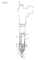
- the electromagnetic actuator has a main body part 70, which is composed of a base part 70a, a trunk part 70b, a connecting part 70c, a head part 70d, etc.
- a depression having a step-shaped longitudinal cross-section is formed in the upper end surface of the base part 70a, and a valve seat providing member 72 is disposed in this depression.
- a valve seat 74 is formed at the center of one end, the upper end in Fig. 1 , of the valve seat providing member 72.
- An orifice 76 and an outlet path 78 are arranged to extend through the valve seat providing member 72 in the named order.
- the orifice 76 and the outlet path 78 form together the high-pressure path.
- a high-pressure fluid is supplied to the valve seat 74 through the high-pressure path.
- An actuating part, e.g. a valve part 82, formed in the armature 80 is adapted to rest on the valve seat 74 to thereby close the valve seat 74.
- the armature 80 is movable in the upward and downward directions in Fig. 1 , and, when the armature 80 is in the raised position, the valve part 82 is off the valve seat 74.
- the high-pressure fluid flowing out through the valve seat 74 flows out into the low-pressure path 83.
- the low-pressure path 83 is provided around the valve seat providing member 72 by part of the trunk part 70b extending into the above-described depression.
- the low-pressure oil in the low-pressure path 83 is let out through a path which is not shown.
- the ball valve is used to open and close the valve seat, but, according to the embodiment being described, the valve part 82 formed integral with the armature 80 operates to open and close the valve seat 74.
- the armature 80 according to the embodiment is lighter in weight than the one of the described background art.
- the armature 80 has a high-strength portion 84 at its center, as shown in Fig. 3 .
- the high-strength portion 84 is made of a high-strength material having relatively high strength, e.g. steel or titanium, and is disc-shaped.
- a plurality of guided portions, e.g. through-holes 86, are formed in the high-strength portion 84 by removing portions of the high-strength portion 84, e.g. by boring.
- the through-holes 86 extend through the high-strength portion 84 in the vertical direction in Fig. 1 .
- four through-holes 86 are formed, being spaced from each other in the circumferential direction and concentrically arranged.
- a magnetic portion 88 is formed around and in contact with the peripheral surface of the high-strength portion 84.
- the magnetic portion 88 is made of a magnetic material.
- the magnetic portion 88 is a ring-shaped member made of compacted magnetic powder, and is fitted over the high-strength portion 84 to be integral therewith.
- a coil 96 is disposed in a portion within the main body part 70 above the armature 80.
- the coil 96 is wound around a core 98, which functions as a stator.
- the core 98 has, in its central portion, a first magnetic member, e.g. an inner cylindrical portion 98a.
- One end, e.g. a lower end, of the inner cylindrical portion 98a is located above the magnetic portion 88.
- An outer cylindrical portion 98b is disposed, being spaced from the inner cylindrical portion 98b, or, more specifically, outward of the outer periphery of the armature 80.
- One end e.g.
- a lower end, of the outer cylindrical portion 98b is located at a level above the upper surface of the magnetic portion 88.
- the other ends, e.g. the upper ends, of the inner and outer cylindrical portions 98a and 98b are at the same level and are coupled to each other by a connecting portion 98c.
- the coil 96 is wound within the space formed between these cylindrical portions 98a and 98b.
- the outer cylindrical portion 98b is shorter in length than the inner cylindrical portion 98a.
- a second magnetic member e.g. an annular magnetic flux concentrating member 100, is disposed to extend from the lower end of the outer cylindrical portion 98b to a location near the inner cylindrical portion 98a.
- a gap is disposed between the inner circumferential surface of the magnetic flux concentrating member 100 and the inner cylindrical member 98a.
- the magnetic flux concentrating member 100 is in contact with the outer cylindrical portion 98b.
- a gap is formed between the armature 80 and the inner cylindrical portion 98a.
- the gap between the inner circumferential surface of the magnetic flux concentrating member 100 and the inner cylindrical member 98a is larger than the gap formed between the armature 80 and the inner cylindrical portion 98a when the coil 96 is de-energized.
- the inner edge of the magnetic flux concentrating member 100 on the side nearer to the coil 96 is beveled.
- the gap between the beveled portion and the inner cylindrical portion 98a is larger than the gap between the inner circumferential surface of the magnetic flux concentrating member 100 and the inner cylindrical portion 98a on the side nearer to the armature 80, and is gradually reduced from the largest gap at the location nearest to the coil 96 toward a location nearer toward the armature 80.
- the gap between the magnetic flux concentrating member 100 and the inner cylindrical portion 98a is kept constant.
- the density of the magnetic flux extending from the portion nearer to the coil 96 of the magnetic flux concentrating member 100 directly to the inner cylindrical portion 98a can be low.
- the outer periphery of the armature 80 extends outward of the inner periphery of the magnetic flux concentrating member 100, but not to the outer cylindrical portion 98b. In other words, the armature 80 and the magnetic flux concentrating member 100 overlap each other.
- the lower end of the inner cylindrical portion 98a is located above the magnetic portion 88 of the armature 80.
- the magnetic flux generated by the coil 96 concentrates on the outer cylindrical portion 98b, the magnetic flux concentrating member 100, the magnetic portion 88 of the armature 80, the inner cylindrical portion 98a and the connecting portion 98c, and thus the magnetic flux density is high, as indicated by broken lines in Fig. 2 .
- the density of the magnetic flux directed from the magnetic flux concentrating member 100 directly to the inner cylindrical portion 98a is significantly low. Then, when the coil 96 is energized, the magnetic flux generated by the coil 96 passes through the armature 80 efficiently.
- the armature 80 is efficiently magnetized and attracted by the core 98 at a high speed. Since the armature 80 can be efficiently magnetized, there is no need to use an armature 80 having such a large diameter that its outer periphery would be located near the outer periphery of the outer cylindrical portion 98b. Thus, the armature 80 can be smaller.
- the shapes of the core 98 and the magnetic flux concentrating member 100 are not limited to the ones described above, but the components may be formed in other separate arrangements.
- the magnetic flux concentrating member 100 and the outer cylindrical portion 98b may be formed integral with each other, with the inner cylindrical portion 98a and the outer cylindrical portion 98b formed as separate components.
- Guides e.g. guide pins 102 are inserted into predetermined ones of the above-described four through-holes 86 in the high-strength portion 84.
- the guide pins 102 are inserted into two of the through-holes 86 which face each other across the center of the high-strength portion 84.
- the proximal ends of these guide pins 102 are placed in and secured to holes formed in the valve seat providing member 72.
- the guide pins 102 guide the armature 80 as the armature 80 moves upward or downward when the coil 96 is energized or de-energized, as described above.
- the through-holes 86 guided by the guide pins 102 are formed in the high-strength portion 84 where no cracks should be formed by forming the through-holes 86. As is seen in Fig. 2 , the through-holes 86 are located in the high-strength portion 84 away from the portion of the armature 80 where the magnetic flux is concentrated when the coil 96 is energized. Thus, the through-holes 86 do not interrupt the concentration of the magnetic flux, and the armature 80 can move at a high speed.
- a coil spring 104 Within the inner cylindrical portion 98a of the core 98, disposed is elastic means, e.g. a coil spring 104, of which one end is in contact with the magnetic portion 88 of the armature 80, and the other end of which is in contact with the head part 70d of the main body part 70 with a spring rest 106 disposed therebetween, as shown in Fig. 1 .
- the coil spring 104 is compressed against its spring force when the armature 80 is raised in response to energization of the coil 96, and quickly lowers the armature 80 onto the valve seat 74 through its spring force in response to de-energization of the coil 96.
- the through-holes 86 guided along the guide pins 102 of the electromagnetic actuator of the present invention are formed in the magnetic portion 88 of the armature 80, as described above, and the magnetic portion 88 is formed in an area where the density of magnetic flux from the coil 96 is low. Therefore the magnetic force acting to attract the armature 80 is not weakened by the presence of the through-holes 86, which further helps the armature 80 to be attracted at a high speed. Further, since the valve part 82 is formed integral with the armature 80, there is no need for forming an abutting portion on the armature 80 as in the prior art valve. Accordingly, the armature 80 can be light in weight and can move more quickly.
- the magnetic portion 88 of the armature 80 is made of compacted magnetic powder, which results in reduced eddy current. With eddy current reduced, the magnetic attractive force can be larger, which results in further quick movement of the armature 80. Since the electromagnetic actuator of this invention employs an arrangement in which a plurality of through-holes 86 are formed and the guide pins 102 are provided in some of them, one or more of the through-holes 86 well guided by the guide pins 102 can be selectively used. This results in improved guiding performance, and, can reduce the number of adjustments to be done to the through-holes 86 which otherwise would be required for improving the guiding performance. In addition, the through-holes 86 through which no guide pins 102 are inserted can function as oil releasers.
- the present invention has been described as being embodied in a fuel injection valve for a common rail system, but it is not limited to such use.
- the invention can be embodied in any other valves which are arranged to operate to flow a high-pressure fluid into a lower-pressure side when they are opened, or it can be arranged to open or close a contact in response to the movement of an actuating part other than a valve, e.g. the armature 80, toward the stator.
Abstract
Description
- This invention relates to an electromagnetic actuator for use in fuel injection valves, for example.
- An example of electromagnetic actuators used in a fuel injection valve of a common rail system is disclosed in Patent Literature 1. The fuel injection valve disclosed in Patent Literature 1 is composed of components including a
nozzle body 2, aneedle 3, aholder body 4, anorifice plate 6, and anelectromagnetic unit 8, as shown inFig. 4 . Thenozzle body 2 is coupled by aretaining nut 10 to the lower end portion of thebody holder 4 with theorifice plate 6 disposed therebetween. Aguide hole 12 is formed in thenozzle body 2 to extend therethrough from the top end surface to the tip end of thenozzle body 2. Theneedle 3 is disposed in theguide hole 12 in such a manner that it can freely slide in theguide hole 12. Aninjection port 14 is formed in the tip end of theguide hole 12 through which fuel is injected when theneedle 3 moves upward. A high-pressure path 16 is formed by a gap between the inner circumferential surface of theguide hole 12 and the outer circumferential surface of theneedle 3. The high-pressure path 16 guides highly pressurized fuel to theinjection port 14. At a location between the two ends of theguide hole 12, afuel reservoir 18 is formed by enlarging the inner diameter of theguide hole 12. The upper end of the high-pressure path 16 opens in the top end surface of thenozzle body 2 and is connected to a high-pressure path 20 in theorifice plate 6. The high-pressure path 20 is connected via a high-pressure path 22 in theholder body 4 to apipe joint 24 disposed at the upper end of theholder body 4, and thepipe joint 24 is supplied with high-pressure fuel from a common rail. - A cylindrical spring seat 26 is press-fitted into and secured to the
guide hole 12, and aspring 28 is disposed between the spring seat 26 and theneedle 3. Thespring 28 urges theneedle 3 in the direction to close the valve, or in the downward direction inFig. 4 . The inner circumferential surface of the spring seat 26 provides a back-pressure chamber 30 for providing a pressure of high-pressure fuel to the upper end surface of theneedle 3 as a back pressure. This back pressure also urges theneedle 3 in the valve-closing direction. The pressure of the high-pressure fuel in thefuel reservoir 18 urges theneedle 3 in the direction to open the valve, or in the upward direction inFig. 4 . - As shown in
Fig. 5 , aninlet path 32 and anoutlet path 34 are formed in theorifice plate 6. Theinlet path 32 is a path through which high-pressure fuel flows from the high-pressure path 20 into the back-pressure chamber 30, and anoutlet path 34 is a path through which the high-pressure fuel flows from the back-pressure chamber 30 to a low pressure side. - The
electromagnetic unit 8 is housed in theholder body 4. Theelectromagnetic unit 8 includes astator 38 having anelectromagnetic coil 36 wound around a plastic bobbin. Theelectromagnetic unit 8 includes also anarmature 40 facing and movable relative to thestator 38. Theelectromagnetic unit 8 further includes aball valve 42 movable with thearmature 40 to open and close theoutlet path 34. Thestator 38 has, in its center, a vertically extendingspring housing hole 44 in which aspring 46 is housed. Thespring 46 presses thearmature 40 so that theball valve 42 is pressed toward theoutlet path 34. The lower portion of thestator 38 functions as a valve chest in which theball valve 42 is housed and which is filled with low-pressure fuel flowing from theoutlet path 34. Anannular groove 48 is formed in the upper surface of theorifice plate 6. Astraight groove 50 extends outward from theannular groove 48, and the low-pressure fuel in the valve chest flows out into a low-pressure path 52 through thegroove 50. - The
armature 40 has adisc member 54, which is disposed to face thestator 38 and form a magnetic circuit with thestator 38. Apedestal 56 is formed in the center of thedisc member 54, and anabutting portion 58 extends from thepedestal 56 toward theball valve 42. Theball valve 42 sits in theabutting portion 58. A plurality of through-holes 60 are concentrically formed in thedisc member 54.Guide pins 62 are inserted into some of the through-holes 60. Theguide pins 62 are secured to theorifice plate 6. The through-holes 60 are formed at such locations as to interrupt the magnetic circuit formed by thedisc member 54 and thestator 38. Amagnetic member 64 is disposed on the lower surface of theelectromagnetic coil 36. Themagnetic member 64 is an annular member which is fitted over a projectingportion 66 formed in the lower portion of thestator 38, and extends from the outer periphery to therise 65 of thestator 38. Themagnetic member 64 is in contact with theprojecting portion 66. - In a state where no electric power is being supplied to the
electromagnetic coil 36, theball valve 42 closes theoutlet path 34, and, therefore, the hydraulic pressure in the back-pressure chamber 30 plus the force given by thespring 28 to urge theneedle 3 in the direction to close the valve is larger than the hydraulic pressure in thefuel reservoir 18 which acts to urge theneedle 3 in the direction to open the valve. Accordingly, theneedle 3 closes theinjection port 14 so that the fuel is not injected. When electric power is supplied to theelectromagnetic coil 36, magnetic flux is generated around theelectromagnetic coil 36, so that thestator 38 and thearmature 40 are magnetized, causing thearmature 40 to be attracted toward thestator 38. As a result, thearmature 40 moves toward thestator 38 against the force of thespring 46, being guided by theguide pins 62. This causes theball valve 42, receiving the hydraulic pressure in the back-pressure chamber 30, to open theoutlet path 34 whereby the high-pressure fuel in the back-pressure chamber 30 is released into the valve chest of theball valve 42. Then, the hydraulic pressure in the back-pressure chamber 30 decreases so that the force to move theneedle 3 in the direction to open the valve becomes greater. This makes theneedle 3 move upward so that the fuel is injected through theinjection port 14. -
- Patent Literature 1: Japan Patent Publication
2010-174820A - According to Patent Literature 1, when the
electromagnetic coil 36 of the electromagnetic valve is energized, the magnetic flux generated by theelectromagnetic coil 36 flows from themagnetic member 64 through thearmature 40 to the projectingportion 66 of thestator 38, and also flows from themagnetic member 64 directly to the projectingportion 66. This means that only part of the magnetic force provided by theelectromagnetic coil 36 can act to attract thearmature 40. Then, thearmature 40 cannot be swiftly moved toward thestator 38. Electromagnetic valves to be used in common rail systems are required to move at a high speed, but the technology disclosed in Patent Literature 1 cannot fulfill this requirement. - An object of the present invention is to provide an electromagnetic actuator having a higher operating speed.
- According to one embodiment of the present invention, the electromagnetic valve includes a main body in which a coil is housed. A first magnetic member is disposed within the coil, and an armature adapted to be attracted by the coil is disposed, being spaced from the first magnetic member. An actuating part is formed integral with the armature. A second magnetic member is disposed on the armature side of the coil with a space disposed between the first and second magnetic members. It is desirable for the second magnetic member to overlap the armature in its portion, e.g. in its outer peripheral portion. Also, it is desirable for the armature to overlap the first magnetic member. The spacing between the first and second magnetic members is larger than the spacing between the armature and the coil.
- The spacing between the first and second magnetic members of the electromagnetic actuator with the arrangement described is larger than the spacing between the armature and the first magnetic member. Therefore the magnetic flux which has been generated by the coil when it is energized and has passed through the second magnetic member hardly enters into the first magnetic member directly, but it enters into the armature and, then, into the first magnetic member. As a result, the armature is magnetized well and swiftly moves toward the first magnetic member. Accordingly, the actuating part formed on the armature also moves swiftly.
- The end surface of the second magnetic member, which faces the first magnetic member may be formed to have its coil side located remoter from its first magnetic member side than its armature side. With such arrangement, the amount of the magnetic flux directed from the second magnetic member directly to the first magnetic member can be smaller, and a larger part of the magnetic flux can be directed to the armature, which results in faster movement of the armature.
- As described above, an armature of an electromagnetic valve according to the present invention can move at a higher speed, and therefore an electromagnetic valve suitable for use in a common rail system, for example, can be provided.
-
- [
Figure 1] Fig. 1 is an enlarged cross-sectional view of part of an electromagnetic actuator according to an embodiment of the present invention. - [
Figure 2] Fig. 2 is a further enlarged cross-sectional view of part of the electromagnetic actuator ofFig. 1 . - [
Figure 3] Fig. 3 is a transverse cross-sectional view of an armature used in the electromagnetic actuator ofFig. 1 . - [
Figure 4] Fig. 4 is a side view of a fuel injection valve in which an electromagnetic actuator according to a prior art is used. - [
Figure 5] Fig. 5 is an enlarged cross-sectional view of part of the fuel injection valve ofFig. 4 . - Like the above-described background art electromagnetic actuator, a electromagnetic actuator according to one embodiment of the present invention is used in a fuel injection valve for use in a common rail system. The electromagnetic actuator is arranged such that, when electric power is supplied to a coil thereof, an armature is moved to make a high-pressure fluid flow into a low-pressure path. The flow of the high-pressure fluid into the low-pressure path causes a nozzle, which is in a position to close an injection port, to move, which, in turn, causes the high-pressure fuel to be supplied to a cylinder of a diesel engine through the injection port.
- As shown in
Fig. 1 , the electromagnetic actuator has amain body part 70, which is composed of abase part 70a, atrunk part 70b, a connectingpart 70c, a head part 70d, etc. In the upper end surface of thebase part 70a, a depression having a step-shaped longitudinal cross-section is formed, and a valveseat providing member 72 is disposed in this depression. At the center of one end, the upper end inFig. 1 , of the valveseat providing member 72, avalve seat 74 is formed. Anorifice 76 and anoutlet path 78 are arranged to extend through the valveseat providing member 72 in the named order. Theorifice 76 and theoutlet path 78 form together the high-pressure path. A high-pressure fluid is supplied to thevalve seat 74 through the high-pressure path. - An actuating part, e.g. a
valve part 82, formed in thearmature 80 is adapted to rest on thevalve seat 74 to thereby close thevalve seat 74. As will be described later, thearmature 80 is movable in the upward and downward directions inFig. 1 , and, when thearmature 80 is in the raised position, thevalve part 82 is off thevalve seat 74. When thevalve part 82 is off thevalve seat 74, the high-pressure fluid flowing out through thevalve seat 74 flows out into the low-pressure path 83. The low-pressure path 83 is provided around the valveseat providing member 72 by part of thetrunk part 70b extending into the above-described depression. The low-pressure oil in the low-pressure path 83 is let out through a path which is not shown. In the valve shown according to the above-described background art, the ball valve is used to open and close the valve seat, but, according to the embodiment being described, thevalve part 82 formed integral with thearmature 80 operates to open and close thevalve seat 74. There is no need for forming, in thearmature 80, the abutting portion to hold the ball valve, which is required for the valve of the background art, and, thus, thearmature 80 according to the embodiment is lighter in weight than the one of the described background art. - The
armature 80 has a high-strength portion 84 at its center, as shown inFig. 3 . The high-strength portion 84 is made of a high-strength material having relatively high strength, e.g. steel or titanium, and is disc-shaped. A plurality of guided portions, e.g. through-holes 86, are formed in the high-strength portion 84 by removing portions of the high-strength portion 84, e.g. by boring. The through-holes 86 extend through the high-strength portion 84 in the vertical direction inFig. 1 . For example, four through-holes 86 are formed, being spaced from each other in the circumferential direction and concentrically arranged. Amagnetic portion 88 is formed around and in contact with the peripheral surface of the high-strength portion 84. Themagnetic portion 88 is made of a magnetic material. For example, themagnetic portion 88 is a ring-shaped member made of compacted magnetic powder, and is fitted over the high-strength portion 84 to be integral therewith. - A
coil 96 is disposed in a portion within themain body part 70 above thearmature 80. Thecoil 96 is wound around acore 98, which functions as a stator. As shown inFig. 2 , thecore 98 has, in its central portion, a first magnetic member, e.g. an innercylindrical portion 98a. One end, e.g. a lower end, of the innercylindrical portion 98a is located above themagnetic portion 88. An outercylindrical portion 98b is disposed, being spaced from the innercylindrical portion 98b, or, more specifically, outward of the outer periphery of thearmature 80. One end, e.g. a lower end, of the outercylindrical portion 98b is located at a level above the upper surface of themagnetic portion 88. The other ends, e.g. the upper ends, of the inner and outercylindrical portions portion 98c. Thecoil 96 is wound within the space formed between thesecylindrical portions - The outer
cylindrical portion 98b is shorter in length than the innercylindrical portion 98a. A second magnetic member, e.g. an annular magneticflux concentrating member 100, is disposed to extend from the lower end of the outercylindrical portion 98b to a location near the innercylindrical portion 98a. A gap is disposed between the inner circumferential surface of the magneticflux concentrating member 100 and the innercylindrical member 98a. The magneticflux concentrating member 100 is in contact with the outercylindrical portion 98b. When thecoil 96 is de-energized, a gap is formed between thearmature 80 and the innercylindrical portion 98a. The gap between the inner circumferential surface of the magneticflux concentrating member 100 and the innercylindrical member 98a is larger than the gap formed between thearmature 80 and the innercylindrical portion 98a when thecoil 96 is de-energized. - The inner edge of the magnetic
flux concentrating member 100 on the side nearer to thecoil 96 is beveled. The gap between the beveled portion and the innercylindrical portion 98a is larger than the gap between the inner circumferential surface of the magneticflux concentrating member 100 and the innercylindrical portion 98a on the side nearer to thearmature 80, and is gradually reduced from the largest gap at the location nearest to thecoil 96 toward a location nearer toward thearmature 80. In the portion which is not beveled, the gap between the magneticflux concentrating member 100 and the innercylindrical portion 98a is kept constant. Since the gap between the magneticflux concentrating member 100 in its portion nearer to thecoil 96 where the magnetic force is relatively large and the innercylindrical portion 98a is large, the density of the magnetic flux extending from the portion nearer to thecoil 96 of the magneticflux concentrating member 100 directly to the innercylindrical portion 98a can be low. - The outer periphery of the
armature 80 extends outward of the inner periphery of the magneticflux concentrating member 100, but not to the outercylindrical portion 98b. In other words, thearmature 80 and the magneticflux concentrating member 100 overlap each other. The lower end of the innercylindrical portion 98a is located above themagnetic portion 88 of thearmature 80. - When the
coil 96 is energized, the magnetic flux generated by thecoil 96 concentrates on the outercylindrical portion 98b, the magneticflux concentrating member 100, themagnetic portion 88 of thearmature 80, the innercylindrical portion 98a and the connectingportion 98c, and thus the magnetic flux density is high, as indicated by broken lines inFig. 2 . On the other hand, because of the larger gap between the magneticflux concentrating member 100 and the innercylindrical portion 98a, the density of the magnetic flux directed from the magneticflux concentrating member 100 directly to the innercylindrical portion 98a is significantly low. Then, when thecoil 96 is energized, the magnetic flux generated by thecoil 96 passes through thearmature 80 efficiently. As a result, thearmature 80 is efficiently magnetized and attracted by the core 98 at a high speed. Since thearmature 80 can be efficiently magnetized, there is no need to use anarmature 80 having such a large diameter that its outer periphery would be located near the outer periphery of the outercylindrical portion 98b. Thus, thearmature 80 can be smaller. It should be noted that the shapes of thecore 98 and the magneticflux concentrating member 100 are not limited to the ones described above, but the components may be formed in other separate arrangements. For example, the magneticflux concentrating member 100 and the outercylindrical portion 98b may be formed integral with each other, with the innercylindrical portion 98a and the outercylindrical portion 98b formed as separate components. - Guides, e.g. guide pins 102 are inserted into predetermined ones of the above-described four through-
holes 86 in the high-strength portion 84. For example, the guide pins 102 are inserted into two of the through-holes 86 which face each other across the center of the high-strength portion 84. The proximal ends of these guide pins 102 are placed in and secured to holes formed in the valveseat providing member 72. The guide pins 102 guide thearmature 80 as thearmature 80 moves upward or downward when thecoil 96 is energized or de-energized, as described above. The through-holes 86 guided by the guide pins 102 are formed in the high-strength portion 84 where no cracks should be formed by forming the through-holes 86. As is seen inFig. 2 , the through-holes 86 are located in the high-strength portion 84 away from the portion of thearmature 80 where the magnetic flux is concentrated when thecoil 96 is energized. Thus, the through-holes 86 do not interrupt the concentration of the magnetic flux, and thearmature 80 can move at a high speed. - Within the inner
cylindrical portion 98a of the core 98, disposed is elastic means, e.g. acoil spring 104, of which one end is in contact with themagnetic portion 88 of thearmature 80, and the other end of which is in contact with the head part 70d of themain body part 70 with aspring rest 106 disposed therebetween, as shown inFig. 1 . Thecoil spring 104 is compressed against its spring force when thearmature 80 is raised in response to energization of thecoil 96, and quickly lowers thearmature 80 onto thevalve seat 74 through its spring force in response to de-energization of thecoil 96. - The through-
holes 86 guided along the guide pins 102 of the electromagnetic actuator of the present invention are formed in themagnetic portion 88 of thearmature 80, as described above, and themagnetic portion 88 is formed in an area where the density of magnetic flux from thecoil 96 is low. Therefore the magnetic force acting to attract thearmature 80 is not weakened by the presence of the through-holes 86, which further helps thearmature 80 to be attracted at a high speed. Further, since thevalve part 82 is formed integral with thearmature 80, there is no need for forming an abutting portion on thearmature 80 as in the prior art valve. Accordingly, thearmature 80 can be light in weight and can move more quickly. Themagnetic portion 88 of thearmature 80 is made of compacted magnetic powder, which results in reduced eddy current. With eddy current reduced, the magnetic attractive force can be larger, which results in further quick movement of thearmature 80. Since the electromagnetic actuator of this invention employs an arrangement in which a plurality of through-holes 86 are formed and the guide pins 102 are provided in some of them, one or more of the through-holes 86 well guided by the guide pins 102 can be selectively used. This results in improved guiding performance, and, can reduce the number of adjustments to be done to the through-holes 86 which otherwise would be required for improving the guiding performance. In addition, the through-holes 86 through which no guide pins 102 are inserted can function as oil releasers. When thearmature 80 moves, oil is released out from or supplied to the space between thearmature 80 and thecoil 96 through the through-holes 86 with no guide pins inserted. In addition to the through-holes 86, holes 90 are formed above thecoil 96, which operate to release oil like the through-holes 86 free of the guide pins 102. - The present invention has been described as being embodied in a fuel injection valve for a common rail system, but it is not limited to such use. The invention can be embodied in any other valves which are arranged to operate to flow a high-pressure fluid into a lower-pressure side when they are opened, or it can be arranged to open or close a contact in response to the movement of an actuating part other than a valve, e.g. the
armature 80, toward the stator. -
- 70: Main Body Part
- 74: Valve Seat
- 80: Armature
- 82: Valve Part (Actuating Part)
- 96: Coil
- 98a: Inner Cylindrical Portion (First Magnetic Member)
- 100: Magnetic Flux Concentrating Member (Second Magnetic Member)
Claims (2)
- An electromagnetic actuator comprising:a main body;a coil housed in said main body;a first magnetic member disposed inward of said coilan armature adapted to be attracted by said coil, and disposed with a gap disposed between said first magnetic member and said armature;a second magnetic member disposed on an armature side of said coil with a gap disposed between said second magnetic member and said first magnetic member; andan actuating part formed integral with said armature;said gap between said first magnetic member and said second magnetic member being larger than said gap between said armature and said first magnetic member.
- An electromagnetic actuator according to Claim 1, wherein:an end surface of said second magnetic member facing said first magnetic member is formed in such a manner that said end surface in a portion thereof nearer to said coil is farther from said first magnetic member than in a portion nearer to said armature.
Applications Claiming Priority (2)
| Application Number | Priority Date | Filing Date | Title |
|---|---|---|---|
| JP2011212352A JP2013072498A (en) | 2011-09-28 | 2011-09-28 | Electromagnetic actuator |
| PCT/JP2012/074358 WO2013047418A1 (en) | 2011-09-28 | 2012-09-24 | Solenoid actuator |
Publications (2)
| Publication Number | Publication Date |
|---|---|
| EP2749799A1 true EP2749799A1 (en) | 2014-07-02 |
| EP2749799A4 EP2749799A4 (en) | 2015-06-24 |
Family
ID=47995450
Family Applications (1)
| Application Number | Title | Priority Date | Filing Date |
|---|---|---|---|
| EP12835134.3A Withdrawn EP2749799A4 (en) | 2011-09-28 | 2012-09-24 | Solenoid actuator |
Country Status (6)
| Country | Link |
|---|---|
| US (1) | US20140240068A1 (en) |
| EP (1) | EP2749799A4 (en) |
| JP (1) | JP2013072498A (en) |
| KR (1) | KR20140063877A (en) |
| CN (1) | CN103842699A (en) |
| WO (1) | WO2013047418A1 (en) |
Cited By (1)
| Publication number | Priority date | Publication date | Assignee | Title |
|---|---|---|---|---|
| WO2018114111A1 (en) * | 2016-12-22 | 2018-06-28 | Robert Bosch Gmbh | Fuel injector and use thereof |
Families Citing this family (3)
| Publication number | Priority date | Publication date | Assignee | Title |
|---|---|---|---|---|
| JP6262482B2 (en) * | 2013-10-01 | 2018-01-17 | ナブテスコ株式会社 | Electromagnetic actuator |
| DE102013224719A1 (en) * | 2013-12-03 | 2015-06-03 | Robert Bosch Gmbh | Magnetic assembly for a solenoid valve |
| KR101628124B1 (en) | 2014-05-27 | 2016-06-21 | 현대자동차 주식회사 | Control system of flowing air into vehicle engine room |
Family Cites Families (13)
| Publication number | Priority date | Publication date | Assignee | Title |
|---|---|---|---|---|
| US5083747A (en) * | 1991-01-28 | 1992-01-28 | Siemens Automotive L.P. | Hat shaped armature for solenoid valve |
| IT227711Y1 (en) * | 1992-12-29 | 1997-12-15 | Elasis Sistema Ricerca Fiat | ELECTROMAGNETIC CONTROLLED METERING VALVE FOR A FUEL INJECTOR |
| EP0781915A1 (en) * | 1995-12-26 | 1997-07-02 | General Motors Corporation | Fuel injector |
| JPH10122080A (en) * | 1996-10-17 | 1998-05-12 | Denso Corp | Accumulative fuel injector |
| JP2002310029A (en) * | 2001-04-10 | 2002-10-23 | Denso Corp | Fuel injection valve |
| JP2003314730A (en) * | 2002-04-19 | 2003-11-06 | Hitachi Unisia Automotive Ltd | Solenoid valve |
| JP3887336B2 (en) * | 2003-03-24 | 2007-02-28 | 株式会社ケーヒン | Electromagnetic fuel injection valve |
| JP2006194237A (en) * | 2004-12-14 | 2006-07-27 | Denso Corp | Electromagnetic actuator |
| JP2007205234A (en) * | 2006-02-01 | 2007-08-16 | Denso Corp | Fuel injection valve |
| US7748683B1 (en) * | 2007-02-23 | 2010-07-06 | Kelly Edmund F | Electrically controlled proportional valve |
| JP2009103050A (en) * | 2007-10-23 | 2009-05-14 | Denso Corp | Electromagnetic drive device |
| US8083206B2 (en) * | 2008-07-08 | 2011-12-27 | Caterpillar Inc. | Precision ground armature assembly for solenoid actuator and fuel injector using same |
| JP2010174820A (en) | 2009-01-30 | 2010-08-12 | Denso Corp | Fuel injection valve |
-
2011
- 2011-09-28 JP JP2011212352A patent/JP2013072498A/en active Pending
-
2012
- 2012-09-24 KR KR1020147010820A patent/KR20140063877A/en not_active Application Discontinuation
- 2012-09-24 EP EP12835134.3A patent/EP2749799A4/en not_active Withdrawn
- 2012-09-24 US US14/347,340 patent/US20140240068A1/en not_active Abandoned
- 2012-09-24 CN CN201280047535.3A patent/CN103842699A/en active Pending
- 2012-09-24 WO PCT/JP2012/074358 patent/WO2013047418A1/en active Application Filing
Cited By (1)
| Publication number | Priority date | Publication date | Assignee | Title |
|---|---|---|---|---|
| WO2018114111A1 (en) * | 2016-12-22 | 2018-06-28 | Robert Bosch Gmbh | Fuel injector and use thereof |
Also Published As
| Publication number | Publication date |
|---|---|
| US20140240068A1 (en) | 2014-08-28 |
| WO2013047418A1 (en) | 2013-04-04 |
| EP2749799A4 (en) | 2015-06-24 |
| CN103842699A (en) | 2014-06-04 |
| KR20140063877A (en) | 2014-05-27 |
| JP2013072498A (en) | 2013-04-22 |
Similar Documents
| Publication | Publication Date | Title |
|---|---|---|
| EP2749800B1 (en) | Solenoid valve | |
| US9273791B2 (en) | Pilot solenoid valve | |
| EP1619384B1 (en) | Fuel injector provided with a high flexibility plunger | |
| EP1878908B1 (en) | Electromagnetic fuel injection valve | |
| CN1776214B (en) | Fuel injector with electromagnetic actuation of the plunger | |
| EP2631465A1 (en) | Solenoid valve | |
| EP2749799A1 (en) | Solenoid actuator | |
| JP2007064364A (en) | Solenoid valve | |
| EP2320066A1 (en) | Electromagnetic actuator | |
| US7946276B2 (en) | Protection device for a solenoid operated valve assembly | |
| EP2221516A1 (en) | Electromagnetic valve | |
| JP6639820B2 (en) | Electromagnetic fuel injector with hydraulic brake | |
| EP2194543A1 (en) | Solenoid actuator | |
| EP2871352B1 (en) | Valve for measuring out fluid | |
| JP5932572B2 (en) | Electromagnetic actuator | |
| JP2018145862A (en) | Fuel injection valve | |
| JP2018091291A (en) | Fuel injection valve | |
| KR101589828B1 (en) | Solenoid actuator | |
| JP2011196533A (en) | Solenoid valve | |
| JP2010236368A (en) | Fuel injection valve | |
| EP2703633A1 (en) | Valve assembly for an injection valve and injection valve |
Legal Events
| Date | Code | Title | Description |
|---|---|---|---|
| PUAI | Public reference made under article 153(3) epc to a published international application that has entered the european phase |
Free format text: ORIGINAL CODE: 0009012 |
|
| 17P | Request for examination filed |
Effective date: 20140326 |
|
| AK | Designated contracting states |
Kind code of ref document: A1 Designated state(s): AL AT BE BG CH CY CZ DE DK EE ES FI FR GB GR HR HU IE IS IT LI LT LU LV MC MK MT NL NO PL PT RO RS SE SI SK SM TR |
|
| DAX | Request for extension of the european patent (deleted) | ||
| RA4 | Supplementary search report drawn up and despatched (corrected) |
Effective date: 20150528 |
|
| RIC1 | Information provided on ipc code assigned before grant |
Ipc: F02M 51/06 20060101ALI20150521BHEP Ipc: F02M 47/00 20060101ALI20150521BHEP Ipc: F16K 31/06 20060101AFI20150521BHEP |
|
| STAA | Information on the status of an ep patent application or granted ep patent |
Free format text: STATUS: THE APPLICATION IS DEEMED TO BE WITHDRAWN |
|
| 18D | Application deemed to be withdrawn |
Effective date: 20160105 |