EP3091184A1 - Kühlung der voderkante einer turbinenschaufel - Google Patents
Kühlung der voderkante einer turbinenschaufel Download PDFInfo
- Publication number
- EP3091184A1 EP3091184A1 EP16159217.5A EP16159217A EP3091184A1 EP 3091184 A1 EP3091184 A1 EP 3091184A1 EP 16159217 A EP16159217 A EP 16159217A EP 3091184 A1 EP3091184 A1 EP 3091184A1
- Authority
- EP
- European Patent Office
- Prior art keywords
- cooling
- airfoil
- holes
- turbomachinery component
- rows
- Prior art date
- Legal status (The legal status is an assumption and is not a legal conclusion. Google has not performed a legal analysis and makes no representation as to the accuracy of the status listed.)
- Granted
Links
- 238000001816 cooling Methods 0.000 title claims abstract description 178
- 238000004891 communication Methods 0.000 claims abstract description 6
- 239000012530 fluid Substances 0.000 claims abstract description 5
- 238000000034 method Methods 0.000 description 5
- 239000000446 fuel Substances 0.000 description 4
- 238000013461 design Methods 0.000 description 3
- 239000002184 metal Substances 0.000 description 3
- 230000008901 benefit Effects 0.000 description 2
- 230000009467 reduction Effects 0.000 description 2
- 230000003068 static effect Effects 0.000 description 2
- 238000005266 casting Methods 0.000 description 1
- 230000008859 change Effects 0.000 description 1
- 230000006835 compression Effects 0.000 description 1
- 238000007906 compression Methods 0.000 description 1
- 239000002826 coolant Substances 0.000 description 1
- 238000012937 correction Methods 0.000 description 1
- 238000005553 drilling Methods 0.000 description 1
- 238000009760 electrical discharge machining Methods 0.000 description 1
- 239000011888 foil Substances 0.000 description 1
- 230000006872 improvement Effects 0.000 description 1
- 238000009434 installation Methods 0.000 description 1
- 238000004519 manufacturing process Methods 0.000 description 1
- 239000000463 material Substances 0.000 description 1
- 230000007246 mechanism Effects 0.000 description 1
- 238000012986 modification Methods 0.000 description 1
- 230000004048 modification Effects 0.000 description 1
- 230000004044 response Effects 0.000 description 1
Images


Classifications
-
- F—MECHANICAL ENGINEERING; LIGHTING; HEATING; WEAPONS; BLASTING
- F01—MACHINES OR ENGINES IN GENERAL; ENGINE PLANTS IN GENERAL; STEAM ENGINES
- F01D—NON-POSITIVE DISPLACEMENT MACHINES OR ENGINES, e.g. STEAM TURBINES
- F01D5/00—Blades; Blade-carrying members; Heating, heat-insulating, cooling or antivibration means on the blades or the members
- F01D5/12—Blades
- F01D5/14—Form or construction
- F01D5/18—Hollow blades, i.e. blades with cooling or heating channels or cavities; Heating, heat-insulating or cooling means on blades
- F01D5/187—Convection cooling
-
- F—MECHANICAL ENGINEERING; LIGHTING; HEATING; WEAPONS; BLASTING
- F01—MACHINES OR ENGINES IN GENERAL; ENGINE PLANTS IN GENERAL; STEAM ENGINES
- F01D—NON-POSITIVE DISPLACEMENT MACHINES OR ENGINES, e.g. STEAM TURBINES
- F01D25/00—Component parts, details, or accessories, not provided for in, or of interest apart from, other groups
- F01D25/08—Cooling; Heating; Heat-insulation
- F01D25/12—Cooling
-
- F—MECHANICAL ENGINEERING; LIGHTING; HEATING; WEAPONS; BLASTING
- F01—MACHINES OR ENGINES IN GENERAL; ENGINE PLANTS IN GENERAL; STEAM ENGINES
- F01D—NON-POSITIVE DISPLACEMENT MACHINES OR ENGINES, e.g. STEAM TURBINES
- F01D25/00—Component parts, details, or accessories, not provided for in, or of interest apart from, other groups
- F01D25/30—Exhaust heads, chambers, or the like
-
- F—MECHANICAL ENGINEERING; LIGHTING; HEATING; WEAPONS; BLASTING
- F01—MACHINES OR ENGINES IN GENERAL; ENGINE PLANTS IN GENERAL; STEAM ENGINES
- F01D—NON-POSITIVE DISPLACEMENT MACHINES OR ENGINES, e.g. STEAM TURBINES
- F01D5/00—Blades; Blade-carrying members; Heating, heat-insulating, cooling or antivibration means on the blades or the members
- F01D5/12—Blades
- F01D5/14—Form or construction
- F01D5/147—Construction, i.e. structural features, e.g. of weight-saving hollow blades
-
- F—MECHANICAL ENGINEERING; LIGHTING; HEATING; WEAPONS; BLASTING
- F01—MACHINES OR ENGINES IN GENERAL; ENGINE PLANTS IN GENERAL; STEAM ENGINES
- F01D—NON-POSITIVE DISPLACEMENT MACHINES OR ENGINES, e.g. STEAM TURBINES
- F01D5/00—Blades; Blade-carrying members; Heating, heat-insulating, cooling or antivibration means on the blades or the members
- F01D5/12—Blades
- F01D5/14—Form or construction
- F01D5/18—Hollow blades, i.e. blades with cooling or heating channels or cavities; Heating, heat-insulating or cooling means on blades
- F01D5/186—Film cooling
-
- F—MECHANICAL ENGINEERING; LIGHTING; HEATING; WEAPONS; BLASTING
- F01—MACHINES OR ENGINES IN GENERAL; ENGINE PLANTS IN GENERAL; STEAM ENGINES
- F01D—NON-POSITIVE DISPLACEMENT MACHINES OR ENGINES, e.g. STEAM TURBINES
- F01D9/00—Stators
- F01D9/02—Nozzles; Nozzle boxes; Stator blades; Guide conduits, e.g. individual nozzles
- F01D9/04—Nozzles; Nozzle boxes; Stator blades; Guide conduits, e.g. individual nozzles forming ring or sector
- F01D9/041—Nozzles; Nozzle boxes; Stator blades; Guide conduits, e.g. individual nozzles forming ring or sector using blades
-
- F—MECHANICAL ENGINEERING; LIGHTING; HEATING; WEAPONS; BLASTING
- F05—INDEXING SCHEMES RELATING TO ENGINES OR PUMPS IN VARIOUS SUBCLASSES OF CLASSES F01-F04
- F05D—INDEXING SCHEME FOR ASPECTS RELATING TO NON-POSITIVE-DISPLACEMENT MACHINES OR ENGINES, GAS-TURBINES OR JET-PROPULSION PLANTS
- F05D2220/00—Application
- F05D2220/30—Application in turbines
- F05D2220/32—Application in turbines in gas turbines
-
- F—MECHANICAL ENGINEERING; LIGHTING; HEATING; WEAPONS; BLASTING
- F05—INDEXING SCHEMES RELATING TO ENGINES OR PUMPS IN VARIOUS SUBCLASSES OF CLASSES F01-F04
- F05D—INDEXING SCHEME FOR ASPECTS RELATING TO NON-POSITIVE-DISPLACEMENT MACHINES OR ENGINES, GAS-TURBINES OR JET-PROPULSION PLANTS
- F05D2230/00—Manufacture
- F05D2230/10—Manufacture by removing material
- F05D2230/13—Manufacture by removing material using lasers
-
- F—MECHANICAL ENGINEERING; LIGHTING; HEATING; WEAPONS; BLASTING
- F05—INDEXING SCHEMES RELATING TO ENGINES OR PUMPS IN VARIOUS SUBCLASSES OF CLASSES F01-F04
- F05D—INDEXING SCHEME FOR ASPECTS RELATING TO NON-POSITIVE-DISPLACEMENT MACHINES OR ENGINES, GAS-TURBINES OR JET-PROPULSION PLANTS
- F05D2240/00—Components
- F05D2240/10—Stators
- F05D2240/12—Fluid guiding means, e.g. vanes
- F05D2240/121—Fluid guiding means, e.g. vanes related to the leading edge of a stator vane
-
- F—MECHANICAL ENGINEERING; LIGHTING; HEATING; WEAPONS; BLASTING
- F05—INDEXING SCHEMES RELATING TO ENGINES OR PUMPS IN VARIOUS SUBCLASSES OF CLASSES F01-F04
- F05D—INDEXING SCHEME FOR ASPECTS RELATING TO NON-POSITIVE-DISPLACEMENT MACHINES OR ENGINES, GAS-TURBINES OR JET-PROPULSION PLANTS
- F05D2240/00—Components
- F05D2240/20—Rotors
- F05D2240/30—Characteristics of rotor blades, i.e. of any element transforming dynamic fluid energy to or from rotational energy and being attached to a rotor
- F05D2240/303—Characteristics of rotor blades, i.e. of any element transforming dynamic fluid energy to or from rotational energy and being attached to a rotor related to the leading edge of a rotor blade
-
- F—MECHANICAL ENGINEERING; LIGHTING; HEATING; WEAPONS; BLASTING
- F05—INDEXING SCHEMES RELATING TO ENGINES OR PUMPS IN VARIOUS SUBCLASSES OF CLASSES F01-F04
- F05D—INDEXING SCHEME FOR ASPECTS RELATING TO NON-POSITIVE-DISPLACEMENT MACHINES OR ENGINES, GAS-TURBINES OR JET-PROPULSION PLANTS
- F05D2260/00—Function
- F05D2260/20—Heat transfer, e.g. cooling
- F05D2260/202—Heat transfer, e.g. cooling by film cooling
-
- Y—GENERAL TAGGING OF NEW TECHNOLOGICAL DEVELOPMENTS; GENERAL TAGGING OF CROSS-SECTIONAL TECHNOLOGIES SPANNING OVER SEVERAL SECTIONS OF THE IPC; TECHNICAL SUBJECTS COVERED BY FORMER USPC CROSS-REFERENCE ART COLLECTIONS [XRACs] AND DIGESTS
- Y02—TECHNOLOGIES OR APPLICATIONS FOR MITIGATION OR ADAPTATION AGAINST CLIMATE CHANGE
- Y02T—CLIMATE CHANGE MITIGATION TECHNOLOGIES RELATED TO TRANSPORTATION
- Y02T50/00—Aeronautics or air transport
- Y02T50/60—Efficient propulsion technologies, e.g. for aircraft
Definitions
- the present invention relates generally to turbine airfoils, and more specifically to showerhead cooling hole arrangements for turbine airfoils.
- a gas turbine engine includes a turbine section with a plurality of stages of stationary vanes and rotary blades to extract mechanical energy from a hot gas flow passing through the turbine.
- the gas turbine engine efficiency can be increased by providing for a higher temperature of the gas flow entering the turbine.
- the temperature entering the turbine may be limited to the first stage vanes and rotor blades ability to withstand the high temperature.
- One method of allowing for higher temperatures than the material properties of the first stage vanes and blades would allow is to provide for cooling air passages through the airfoils. Since the cooling air used to cool the airfoils is generally bled off from the compressor, it is also desirable to use a minimum amount of bleed off air in order to improve the efficiency of the engine.
- leading edge region cooling configurations in traditional blades and vanes, further improvement is always desirable in order to allow the use of higher operating temperatures and reduced cooling air flow rates through the airfoils, as well as to minimize manufacturing costs.
- present disclosure provides a solution for this need.
- a turbomachinery component comprising: an airfoil section; a cooling passage extending within the airfoil section; a wall defined between the cooling passage and an exterior surface of the airfoil; and at least one row of cooling holes along a cooling portion of the external wall proximate a leading edge of the airfoil for fluid communication between the cooling passage and the exterior surface of the airfoil, wherein the cooling portion of the airfoil wall is thicker than an average adjacent airfoil wall thickness.
- the thickness of the wall at the cooling portion may be at least 50% thicker than the average adjacent airfoil wall thickness and at most 400% thicker than the average adjacent airfoil wall thickness.
- the adjacent walls may include the suction side and pressure side of the airfoil.
- a majority of the cooling holes may have a L/D ratio range of 5-20.
- the rows of cooling holes may be radially spaced along the cooling portion.
- the turbomachinery component may include one row of cooling holes.
- the turbomachinery component may include two rows of cooling holes.
- the turbomachinery component may include three rows of cooling holes.
- the turbomachinery component may include four rows of cooling holes.
- the turbomachinery component may include five rows of cooling holes.
- the number of cooling holes of a first cooling hole row at a first airfoil radial location may be different from the number of cooling holes at a second cooling hole row at a second airfoil radial location.
- At least one row of cooling hole rows may extend partially radially across the airfoil.
- the turbomachinery component may further comprising a row of gill holes along a suction side of the turbine blade relative to the cooling hole rows.
- the turbomachinery component may further comprising a row of gill holes along a pressure side of the turbine blade relative to the cooling hole rows.
- the airfoil may be a turbine blade.
- the airfoil may be a turbine vane.
- the airfoil may be a turbine exhaust case.
- the cooling hole rows may be positioned at the leading edge of the airfoil.
- the cooling hole rows may include holes with a constant cross-sectional area from an inlet of the cooling passage to an exit of the exterior surface of the airfoil.
- the cooling hole rows may include holes with a round metering section and a diffusing section.
- a turbomachinery component includes an airfoil section with a cooling passage extending within the airfoil section.
- a wall is defined between the cooling passage and an exterior surface of the airfoil.
- At least one row of cooling holes is positioned along a cooling portion of the wall proximate a leading edge of the airfoil for fluid communication between the cooling passage and the exterior surface of the airfoil.
- the cooling portion of the airfoil wall is thicker than an average adjacent airfoil wall thickness.
- the airfoil can be a blade or vane for a turbine or compressor, a turbine exhaust case, or any other suitable type of turbine machine airfoil.
- the thickness of the cooling portion of the wall can be at least 50% thicker than the surrounding wall area and can be up to 400% thicker than the surrounding area.
- Each of the cooling holes can have a length over diameter (L/D) ratio range of 5-20.
- the adjacent walls can include the suction side and pressure side of the airfoil.
- the rows of cooling holes can be radially spaced along the cooling portion.
- a majority of the cooling holes can have a L/D ratio range of 5-20.
- the airfoil can include one row, two, three, four, five or any other suitable number of rows of cooling holes.
- the number of cooling holes of a first cooling hole row at a first airfoil radial location can be different from the number of cooling holes of a second cooling hole row at a second air foil radial location.
- the airfoil can include a row of gill holes along a suction side of the airfoil relative to the cooling holes.
- the airfoil can include a row of gill holes along a pressure side of the airfoil relative to the cooling holes.
- the cooling hole rows can be positioned at the leading edge of the airfoil.
- the cooling hole rows can include holes with a constant cross-sectional area from an inlet of the cooling passage to an exit of the exterior surface of the airfoil.
- the cooling hole rows can include holes with a round metering section and a diffusing section.
- FIG. 4 a partial view of an exemplary embodiment of turbomachine airfoil cooling holes in accordance with the disclosure is shown in Fig. 4 and is designated generally by reference character 100.
- the arrangement of cooling holes of the present disclosure increases the leading edge effectiveness and improves the overall convection capability which reduces the airfoil leading edge metal temperature.
- Fig. 1 schematically illustrates a gas turbine engine 20.
- the gas turbine engine 20 is disclosed herein as a two-spool turbofan that generally incorporates a fan section 22, a compressor section 24, a combustor section 26 and a turbine section 28.
- Alternative engines might include an augmentor section (not shown) among other systems or features.
- the fan section 22 drives air along a bypass flow path B in a bypass duct defined within a nacelle 15, while the compressor section 24 drives air along a core flow path C for compression and communication into the combustor section 26 then expansion through the turbine section 28.
- the exemplary engine 20 generally includes a low speed spool 30 and a high speed spool 32 mounted for rotation about an engine central longitudinal axis A relative to an engine static structure 36 via several bearing systems 38. It should be understood that various bearing systems 38 at various locations may alternatively or additionally be provided and the location of bearing systems 38 may be varied as appropriate to the application.
- the low speed spool 30 generally includes an inner shaft 40 that interconnects a fan 42, a first (or low) pressure compressor 44 and a first (or low) pressure turbine 46.
- the inner shaft 40 is connected to the fan 42 through a speed change mechanism, which in exemplary gas turbine engine 20 is illustrated as a gear system 48 to drive the fan 42 at a lower speed than the low speed spool 30.
- the high speed spool 32 includes an outer shaft 50 that interconnects a second (or high) pressure compressor 52 and a second (or high) pressure turbine 54.
- a combustor 56 is arranged in exemplary gas turbine 20 between the high pressure compressor 52 and the high pressure turbine 54.
- a mid-turbine frame 57 of the engine static structure 36 is arranged generally between the high pressure turbine 54 and the low pressure turbine 46.
- the mid-turbine frame 57 further supports bearing systems 38 in the turbine section 28.
- the inner shaft 40 and the outer shaft 50 are concentric and rotate via bearing systems 38 about the engine central longitudinal axis A which is collinear with their longitudinal axes.
- the core airflow is compressed by the low pressure compressor 44 then the high pressure compressor 52, mixed and burned with fuel in the combustor 56, then expanded over the high pressure turbine 54 and low pressure turbine 46.
- the mid-turbine frame 57 includes airfoils 59 which are in the core airflow path C.
- the turbines 46, 54 rotationally drive the respective low speed spool 30 and high speed spool 32 in response to the expansion.
- gear system 48 may be located aft of combustor section 26 or even aft of turbine section 28, and fan section 22 may be positioned forward or aft of the location of gear system 48.
- the engine 20 in one example is a high-bypass geared aircraft engine.
- the engine 20 bypass ratio is greater than about six (6), with an example embodiment being greater than about ten (10)
- the geared architecture is an epicyclic gear train, such as a planetary gear system or other gear system, with a gear reduction ratio of greater than about 2.3 and the low pressure turbine 46 has a pressure ratio that is greater than about five.
- the engine 20 bypass ratio is greater than about ten (10:1)
- the fan diameter is significantly larger than that of the low pressure compressor 44
- the low pressure turbine 46 has a pressure ratio that is greater than about five (5:1).
- Low pressure turbine 46 pressure ratio is pressure measured prior to inlet of low pressure turbine 46 as related to the pressure at the outlet of the low pressure turbine 46 prior to an exhaust nozzle.
- the geared architecture may be an epicycle gear train, such as a planetary gear system or other gear system, with a gear reduction ratio of greater than about 2.3:1. It should be understood, however, that the above parameters are only exemplary of one embodiment of a geared architecture engine and that the present invention is applicable to other gas turbine engines including direct drive turbofans.
- the fan section 22 of the engine 20 is designed for a particular flight condition - typically cruise at about 0.8 Mach (275 ms -1 ) and about 35,000 feet (10688 m).
- the flight condition of 0.8 Mach (275 ms -1 ) and 35,000 ft (10,668 meters), with the engine at its best fuel consumption - also known as "bucket cruise Thrust Specific Fuel Consumption ('TSFC')" - is the industry standard parameter of lbm (g) of fuel being burned divided by lbf (N) of thrust the engine produces at that minimum point.
- Low fan pressure ratio is the pressure ratio across the fan blade alone, without a Fan Exit Guide Vane 79 ("FEGV") system.
- the low fan pressure ratio as disclosed herein according to one non-limiting embodiment is less than about 1.45.
- Low corrected fan tip speed is the actual fan tip speed in ft/sec divided by an industry standard temperature correction of [(Tram °R) /(518.7 °R)] ⁇ 0.5.
- the "Low corrected fan tip speed” as disclosed herein according to one non ⁇ limiting embodiment is less than about 1150 ft/second (350.5 meters/second).
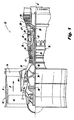
- Fig. 2 illustrates a typical turbine blade 60 for a gas turbine engine 20, known in the art.
- the blade 60 includes an attachment 64 including a platform 66.
- a blade 60 extends from a root 62 coupled to the platform 66 towards a tip 68.
- the blade 60 further includes a leading edge 63 and a trailing edge 67 on either side of longitudinal axis A1 of the turbine blade 60.
- a pressure sidewall 61 and a suction sidewall 69 both extend between the leading edge 63 and the trailing edge 67.
- a cooling passage 70 (shown in Fig. 3 ) is defined within the blade 60 for supplying cooling air towards the leading edge 63.
- Fig. 3 illustrates a prior art cross-sectional view of the turbine blade 60.
- a plurality of cooling rows 72, 74, 76, 78 (shown schematically) is formed at the leading edge 63 from the cooling passage 70 to an external surface 79 of the leading edge.
- Each film cooling row 72, 74, 76, 78 has an inlet 75 connected to the cooling passage 70 and an outlet 77 opening onto the external surface 79.
- the cooling air is diffused at outlet 77 forming a film layer of cooling air on the external surface 79 at the leading edge 63.
- the cooling air is supplied to the cooling passage 70 from the bottom of attachment 64 and, as is typical in many turbine cooling installations, the coolant is supplied by the engine's compressor.
- the blade 100 includes a plurality of film cooling holes 130 forming an array of cooling rows 132, 134, 136, 138 disposed about leading edge 112.
- a blade wall 150 is defined between the cooling passage 142 and the exterior surface 146 of the blade 100.
- a cooling portion 160 is defined between the pressure side 116 and suction side 118 and includes the rows 132, 134, 136, 138 of cooling holes 130.
- the blade wall 150 of the cooling portion 160 has thickness greater than an average of the adjacent wall sections. More specifically, the blade wall 150 thickness is greater than an average thickness of the pressure side 116 and suction side 118.
- a similar region of a blade wall which includes cooling rows 72, 74, 76, and 78 at the leading edge has a uniform thickness with the blade wall at the pressure side and suction side.
- blade wall 150 can be at least 50% thicker than an average of the adjacent wall sections and at most 400% thicker. This increased thickness results in a length over diameter (L/D) ratio of each cooling hole 130 of approximately 5-20. It has been shown that longer cooling holes 130 provide more internal convection on the leading edge 112 of the blade 100. Ultimately this reduces the metal temperature on the leading edge 112 and can be used to reduce the required cooling flow. In the embodiments shown in Figs. 4-8 , the greatest benefit to the longer cooling holes was shown in row 136 although benefits were measured over all cooling holes 130.
- Fig. 4 shows a cross-sectional view of one embodiment of the turbine blade with four rows, 132, 134, 136 and 138 of cooling holes 130.
- the cooling rows 132, 134, 136, 138, and 139 arc depicted in Figs. 4-10 schematically for sake of clarity.
- the cooling holes 132, 134, 136, 138, and 139 may be conventionally manufactured in the blade casting using suitable electrical discharge machining or laser drilling, for example.
- Figs. 5-8 illustrate alternate embodiments with one, two, three, and five rows, respectively. Regardless of the number of rows, each row is radially spaced along the cooling portion 160 of the leading edge 112.
- Typical designs for cooling rows known in the art place at least one row of cooling holes along a stagnation point of the blade.
- the cooling rows 132, 134, 136, 138 of the present disclosure are not limited by location in relation to the stagnation point.
- the cooling holes 130 may be substantially cylindrical or conical in shape.
- the cooling holes 130 may also comprise combinations of cylindrical film cooling holes, diffusive film cooling holes, and film cooling holes of other shapes, geometries, and configurations as known in the art.
- cooling hole row 132 may include holes 130 with a constant cross-sectional area from an inlet 152 of the cooling passage 142 to an exit 154 of the exterior surface 146 of the blade 100.
- cooling hole rows 134 include holes 130 with a round metering section 156 and a diffusing section 158.
- An ejection direction D of the cooling holes is at an angle ⁇ with respect to longitudinal axis A1.
- the angle of the cooling holes along each row may be similar, however, in other embodiments, based on the design of the blade, the angles of the cooling holes within each row may vary.
- Fig. 10 shows schematically embodiments of cooling hole row configurations. As shown in Fig. 10 , where the radial location R is indicated, at least one row of cooling hole rows, for example, row 132, at a first radial location R1, may include a different number of cooling holes (i.e. four holes) from a second radial location, e.g., R2, row 133 which includes one cooling hole.
- Figs. 11 and 12 show additional embodiments of the turbine blade with gill holes on the pressure side and suction side, respectively.
- Gill holes are typically utilized in specific high temperature areas to provide targeted cooling on these particular areas.
- a pressure side row of gill holes 170 and a suction side row gill holes 180 are both located downstream from the pressure and suction sides 116, 118, respectively. Cooling air for the cooling holes 130 and gill holes 170, 180 is supplied from the cooling passage 142.
- the gill holes also have the same structure as the cooling holes 130 with a metering inlet hole 172, 182 followed by an outlet hole 174, 184 at the exterior surface 146.
- cooling hole configurations described above are discussed in relation to turbine blades but can readily be applied any turbomachinery component including turbine vanes, turbine exhaust cases or any other suitable type of turbo machine airfoil.
Landscapes
- Engineering & Computer Science (AREA)
- Mechanical Engineering (AREA)
- General Engineering & Computer Science (AREA)
- Architecture (AREA)
- Turbine Rotor Nozzle Sealing (AREA)
Applications Claiming Priority (1)
| Application Number | Priority Date | Filing Date | Title |
|---|---|---|---|
| US14/707,887 US10077667B2 (en) | 2015-05-08 | 2015-05-08 | Turbine airfoil film cooling holes |
Publications (2)
| Publication Number | Publication Date |
|---|---|
| EP3091184A1 true EP3091184A1 (de) | 2016-11-09 |
| EP3091184B1 EP3091184B1 (de) | 2022-01-12 |
Family
ID=55486595
Family Applications (1)
| Application Number | Title | Priority Date | Filing Date |
|---|---|---|---|
| EP16159217.5A Active EP3091184B1 (de) | 2015-05-08 | 2016-03-08 | Kühlung der vorderkante einer turbinenschaufel |
Country Status (2)
| Country | Link |
|---|---|
| US (1) | US10077667B2 (de) |
| EP (1) | EP3091184B1 (de) |
Cited By (1)
| Publication number | Priority date | Publication date | Assignee | Title |
|---|---|---|---|---|
| CN107367899A (zh) * | 2017-08-21 | 2017-11-21 | 北京航空航天大学 | 一种旋转状态下涡轮动叶前缘气膜拍摄系统 |
Families Citing this family (7)
| Publication number | Priority date | Publication date | Assignee | Title |
|---|---|---|---|---|
| US10519779B2 (en) * | 2016-03-16 | 2019-12-31 | General Electric Company | Radial CMC wall thickness variation for stress response |
| US11047240B2 (en) * | 2017-05-11 | 2021-06-29 | General Electric Company | CMC components having microchannels and methods for forming microchannels in CMC components |
| JP7224928B2 (ja) * | 2019-01-17 | 2023-02-20 | 三菱重工業株式会社 | タービン動翼及びガスタービン |
| US11359494B2 (en) * | 2019-08-06 | 2022-06-14 | General Electric Company | Engine component with cooling hole |
| CN110863864B (zh) * | 2019-12-11 | 2022-05-10 | 沈阳航空航天大学 | 一种内部带有横向蜿蜒交替缩扩短通道的涡轮叶片 |
| WO2023211485A2 (en) * | 2021-10-22 | 2023-11-02 | Raytheon Technologies Corporation | Gas turbine engine article with cooling holes for mitigating recession |
| GB202214883D0 (en) * | 2022-10-10 | 2022-11-23 | Rolls Royce Plc | Aerofoil for a gas turbine engine |
Citations (5)
| Publication number | Priority date | Publication date | Assignee | Title |
|---|---|---|---|---|
| US20050265838A1 (en) * | 2003-03-12 | 2005-12-01 | George Liang | Leading edge diffusion cooling of a turbine airfoil for a gas turbine engine |
| US20060107668A1 (en) * | 2004-11-23 | 2006-05-25 | United Technologies Corporation | Airfoil with supplemental cooling channel adjacent leading edge |
| US20100119377A1 (en) * | 2008-11-12 | 2010-05-13 | Rolls-Royce Plc | Cooling arrangement |
| EP2844839A1 (de) * | 2012-04-23 | 2015-03-11 | General Electric Company | Turbinenschaufel mit lokaler wanddickensteuerung |
| WO2015035363A1 (en) * | 2013-09-09 | 2015-03-12 | United Technologies Corporation | Incidence tolerant engine component |
Family Cites Families (10)
| Publication number | Priority date | Publication date | Assignee | Title |
|---|---|---|---|---|
| US5307637A (en) * | 1992-07-09 | 1994-05-03 | General Electric Company | Angled multi-hole film cooled single wall combustor dome plate |
| US5688104A (en) * | 1993-11-24 | 1997-11-18 | United Technologies Corporation | Airfoil having expanded wall portions to accommodate film cooling holes |
| US5779437A (en) * | 1996-10-31 | 1998-07-14 | Pratt & Whitney Canada Inc. | Cooling passages for airfoil leading edge |
| EP0892151A1 (de) * | 1997-07-15 | 1999-01-20 | Asea Brown Boveri AG | Kühlsystem für den Vorderkantenbereich einer hohlen Gasturbinenschaufel |
| DE19848104A1 (de) * | 1998-10-19 | 2000-04-20 | Asea Brown Boveri | Turbinenschaufel |
| US7300252B2 (en) * | 2004-10-04 | 2007-11-27 | Alstom Technology Ltd | Gas turbine airfoil leading edge cooling construction |
| US8052390B1 (en) * | 2007-10-19 | 2011-11-08 | Florida Turbine Technologies, Inc. | Turbine airfoil with showerhead cooling |
| US20090169394A1 (en) * | 2007-12-28 | 2009-07-02 | General Electric Company | Method of forming cooling holes and turbine airfoil with hybrid-formed cooling holes |
| US9416971B2 (en) * | 2012-02-15 | 2016-08-16 | United Technologies Corporation | Multiple diffusing cooling hole |
| WO2015112225A2 (en) * | 2013-11-25 | 2015-07-30 | United Technologies Corporation | Gas turbine engine airfoil with leading edge trench and impingement cooling |
-
2015
- 2015-05-08 US US14/707,887 patent/US10077667B2/en active Active
-
2016
- 2016-03-08 EP EP16159217.5A patent/EP3091184B1/de active Active
Patent Citations (5)
| Publication number | Priority date | Publication date | Assignee | Title |
|---|---|---|---|---|
| US20050265838A1 (en) * | 2003-03-12 | 2005-12-01 | George Liang | Leading edge diffusion cooling of a turbine airfoil for a gas turbine engine |
| US20060107668A1 (en) * | 2004-11-23 | 2006-05-25 | United Technologies Corporation | Airfoil with supplemental cooling channel adjacent leading edge |
| US20100119377A1 (en) * | 2008-11-12 | 2010-05-13 | Rolls-Royce Plc | Cooling arrangement |
| EP2844839A1 (de) * | 2012-04-23 | 2015-03-11 | General Electric Company | Turbinenschaufel mit lokaler wanddickensteuerung |
| WO2015035363A1 (en) * | 2013-09-09 | 2015-03-12 | United Technologies Corporation | Incidence tolerant engine component |
Cited By (2)
| Publication number | Priority date | Publication date | Assignee | Title |
|---|---|---|---|---|
| CN107367899A (zh) * | 2017-08-21 | 2017-11-21 | 北京航空航天大学 | 一种旋转状态下涡轮动叶前缘气膜拍摄系统 |
| CN107367899B (zh) * | 2017-08-21 | 2019-06-14 | 北京航空航天大学 | 一种旋转状态下涡轮动叶前缘气膜拍摄系统 |
Also Published As
| Publication number | Publication date |
|---|---|
| US20160326886A1 (en) | 2016-11-10 |
| US10077667B2 (en) | 2018-09-18 |
| EP3091184B1 (de) | 2022-01-12 |
Similar Documents
| Publication | Publication Date | Title |
|---|---|---|
| EP3091184B1 (de) | Kühlung der vorderkante einer turbinenschaufel | |
| US20200024964A1 (en) | Cooling hole for a gas turbine engine component | |
| EP2977556B1 (de) | Schaufelblatt, gasturbinenmotoranordnung und zugehöriges kühlverfahren | |
| EP3009599A1 (de) | Gasturbinenbauteil mit filmkühlungsöffnung. | |
| EP3296511A2 (de) | Gasturbinentriebwerksschaufel, zugehöriges gasturbinentriebwerk und verfahren für eine gasturbinentriebwerksschaufel | |
| US11286790B2 (en) | Cooling passages for gas turbine engine component | |
| EP2942488B1 (de) | Laufschaufel für ein gasturbinentriebwerk, gasturbinentriebwerk und verfahren zur kühlung einer laufschaufel für ein gasturbinentriebwerk | |
| EP3091186B1 (de) | Turbinenmotorkomponente mit einem durch einen absatz unterbrochenen axial ausgerichteten verkleidungskernkanal | |
| EP3042041B1 (de) | Gasturbinenmotorflügelturbulator für flügelkriechbeständigkeit | |
| EP2993304A1 (de) | Gasturbinenmotorkomponente mit filmkühlungsloch | |
| US20160251969A1 (en) | Gas turbine engine airfoil | |
| EP3461993B1 (de) | Gasturbinenlaufschaufel | |
| US10738619B2 (en) | Fan cooling hole array | |
| EP3078807B2 (de) | Kühlkanäle für eine gasturbinenmotorkomponente | |
| EP3112596A1 (de) | Gasturbinenmotorschaufel mit biaxialem wandkühlkanal und zugehöriger gasturbinenmotor | |
| US20140165593A1 (en) | Gas turbine engine turbine blade leading edge tip trench cooling | |
| EP3054093B1 (de) | Anordnung von turbulatoren | |
| US20180038236A1 (en) | Gas turbine engine stator vane baffle arrangement | |
| EP3061913B1 (de) | Gasturbinentriebwerksschaufel-kühlkonfiguration mit druckgefälleseparatoren | |
| EP3045666B1 (de) | Tragflächenplattform mit kühlungseinspeisungsöffnungen | |
| WO2014159575A1 (en) | Gas turbine engine multi-vaned stator cooling configuration | |
| EP3477055A1 (de) | Gasturbinenmotorschaufel | |
| WO2015047576A1 (en) | Diffused platform cooling holes | |
| EP2977557B1 (de) | Gekühlte schaufelstruktur und zugehöriges kühlverfahren |
Legal Events
| Date | Code | Title | Description |
|---|---|---|---|
| PUAI | Public reference made under article 153(3) epc to a published international application that has entered the european phase |
Free format text: ORIGINAL CODE: 0009012 |
|
| AK | Designated contracting states |
Kind code of ref document: A1 Designated state(s): AL AT BE BG CH CY CZ DE DK EE ES FI FR GB GR HR HU IE IS IT LI LT LU LV MC MK MT NL NO PL PT RO RS SE SI SK SM TR |
|
| AX | Request for extension of the european patent |
Extension state: BA ME |
|
| STAA | Information on the status of an ep patent application or granted ep patent |
Free format text: STATUS: REQUEST FOR EXAMINATION WAS MADE |
|
| 17P | Request for examination filed |
Effective date: 20170509 |
|
| RBV | Designated contracting states (corrected) |
Designated state(s): AL AT BE BG CH CY CZ DE DK EE ES FI FR GB GR HR HU IE IS IT LI LT LU LV MC MK MT NL NO PL PT RO RS SE SI SK SM TR |
|
| STAA | Information on the status of an ep patent application or granted ep patent |
Free format text: STATUS: EXAMINATION IS IN PROGRESS |
|
| 17Q | First examination report despatched |
Effective date: 20180924 |
|
| STAA | Information on the status of an ep patent application or granted ep patent |
Free format text: STATUS: EXAMINATION IS IN PROGRESS |
|
| GRAP | Despatch of communication of intention to grant a patent |
Free format text: ORIGINAL CODE: EPIDOSNIGR1 |
|
| STAA | Information on the status of an ep patent application or granted ep patent |
Free format text: STATUS: GRANT OF PATENT IS INTENDED |
|
| INTG | Intention to grant announced |
Effective date: 20210209 |
|
| RAP1 | Party data changed (applicant data changed or rights of an application transferred) |
Owner name: RAYTHEON TECHNOLOGIES CORPORATION |
|
| GRAJ | Information related to disapproval of communication of intention to grant by the applicant or resumption of examination proceedings by the epo deleted |
Free format text: ORIGINAL CODE: EPIDOSDIGR1 |
|
| STAA | Information on the status of an ep patent application or granted ep patent |
Free format text: STATUS: EXAMINATION IS IN PROGRESS |
|
| INTC | Intention to grant announced (deleted) | ||
| GRAP | Despatch of communication of intention to grant a patent |
Free format text: ORIGINAL CODE: EPIDOSNIGR1 |
|
| STAA | Information on the status of an ep patent application or granted ep patent |
Free format text: STATUS: GRANT OF PATENT IS INTENDED |
|
| INTG | Intention to grant announced |
Effective date: 20210818 |
|
| GRAS | Grant fee paid |
Free format text: ORIGINAL CODE: EPIDOSNIGR3 |
|
| GRAA | (expected) grant |
Free format text: ORIGINAL CODE: 0009210 |
|
| STAA | Information on the status of an ep patent application or granted ep patent |
Free format text: STATUS: THE PATENT HAS BEEN GRANTED |
|
| AK | Designated contracting states |
Kind code of ref document: B1 Designated state(s): AL AT BE BG CH CY CZ DE DK EE ES FI FR GB GR HR HU IE IS IT LI LT LU LV MC MK MT NL NO PL PT RO RS SE SI SK SM TR |
|
| REG | Reference to a national code |
Ref country code: GB Ref legal event code: FG4D |
|
| REG | Reference to a national code |
Ref country code: CH Ref legal event code: EP |
|
| REG | Reference to a national code |
Ref country code: DE Ref legal event code: R096 Ref document number: 602016068254 Country of ref document: DE |
|
| REG | Reference to a national code |
Ref country code: IE Ref legal event code: FG4D |
|
| REG | Reference to a national code |
Ref country code: AT Ref legal event code: REF Ref document number: 1462510 Country of ref document: AT Kind code of ref document: T Effective date: 20220215 |
|
| REG | Reference to a national code |
Ref country code: LT Ref legal event code: MG9D |
|
| REG | Reference to a national code |
Ref country code: NL Ref legal event code: MP Effective date: 20220112 |
|
| REG | Reference to a national code |
Ref country code: AT Ref legal event code: MK05 Ref document number: 1462510 Country of ref document: AT Kind code of ref document: T Effective date: 20220112 |
|
| PG25 | Lapsed in a contracting state [announced via postgrant information from national office to epo] |
Ref country code: NL Free format text: LAPSE BECAUSE OF FAILURE TO SUBMIT A TRANSLATION OF THE DESCRIPTION OR TO PAY THE FEE WITHIN THE PRESCRIBED TIME-LIMIT Effective date: 20220112 |
|
| PG25 | Lapsed in a contracting state [announced via postgrant information from national office to epo] |
Ref country code: SE Free format text: LAPSE BECAUSE OF FAILURE TO SUBMIT A TRANSLATION OF THE DESCRIPTION OR TO PAY THE FEE WITHIN THE PRESCRIBED TIME-LIMIT Effective date: 20220112 Ref country code: RS Free format text: LAPSE BECAUSE OF FAILURE TO SUBMIT A TRANSLATION OF THE DESCRIPTION OR TO PAY THE FEE WITHIN THE PRESCRIBED TIME-LIMIT Effective date: 20220112 Ref country code: PT Free format text: LAPSE BECAUSE OF FAILURE TO SUBMIT A TRANSLATION OF THE DESCRIPTION OR TO PAY THE FEE WITHIN THE PRESCRIBED TIME-LIMIT Effective date: 20220512 Ref country code: NO Free format text: LAPSE BECAUSE OF FAILURE TO SUBMIT A TRANSLATION OF THE DESCRIPTION OR TO PAY THE FEE WITHIN THE PRESCRIBED TIME-LIMIT Effective date: 20220412 Ref country code: LT Free format text: LAPSE BECAUSE OF FAILURE TO SUBMIT A TRANSLATION OF THE DESCRIPTION OR TO PAY THE FEE WITHIN THE PRESCRIBED TIME-LIMIT Effective date: 20220112 Ref country code: HR Free format text: LAPSE BECAUSE OF FAILURE TO SUBMIT A TRANSLATION OF THE DESCRIPTION OR TO PAY THE FEE WITHIN THE PRESCRIBED TIME-LIMIT Effective date: 20220112 Ref country code: ES Free format text: LAPSE BECAUSE OF FAILURE TO SUBMIT A TRANSLATION OF THE DESCRIPTION OR TO PAY THE FEE WITHIN THE PRESCRIBED TIME-LIMIT Effective date: 20220112 Ref country code: BG Free format text: LAPSE BECAUSE OF FAILURE TO SUBMIT A TRANSLATION OF THE DESCRIPTION OR TO PAY THE FEE WITHIN THE PRESCRIBED TIME-LIMIT Effective date: 20220412 |
|
| PG25 | Lapsed in a contracting state [announced via postgrant information from national office to epo] |
Ref country code: PL Free format text: LAPSE BECAUSE OF FAILURE TO SUBMIT A TRANSLATION OF THE DESCRIPTION OR TO PAY THE FEE WITHIN THE PRESCRIBED TIME-LIMIT Effective date: 20220112 Ref country code: LV Free format text: LAPSE BECAUSE OF FAILURE TO SUBMIT A TRANSLATION OF THE DESCRIPTION OR TO PAY THE FEE WITHIN THE PRESCRIBED TIME-LIMIT Effective date: 20220112 Ref country code: GR Free format text: LAPSE BECAUSE OF FAILURE TO SUBMIT A TRANSLATION OF THE DESCRIPTION OR TO PAY THE FEE WITHIN THE PRESCRIBED TIME-LIMIT Effective date: 20220413 Ref country code: FI Free format text: LAPSE BECAUSE OF FAILURE TO SUBMIT A TRANSLATION OF THE DESCRIPTION OR TO PAY THE FEE WITHIN THE PRESCRIBED TIME-LIMIT Effective date: 20220112 Ref country code: AT Free format text: LAPSE BECAUSE OF FAILURE TO SUBMIT A TRANSLATION OF THE DESCRIPTION OR TO PAY THE FEE WITHIN THE PRESCRIBED TIME-LIMIT Effective date: 20220112 |
|
| PG25 | Lapsed in a contracting state [announced via postgrant information from national office to epo] |
Ref country code: IS Free format text: LAPSE BECAUSE OF FAILURE TO SUBMIT A TRANSLATION OF THE DESCRIPTION OR TO PAY THE FEE WITHIN THE PRESCRIBED TIME-LIMIT Effective date: 20220512 |
|
| REG | Reference to a national code |
Ref country code: DE Ref legal event code: R097 Ref document number: 602016068254 Country of ref document: DE |
|
| PG25 | Lapsed in a contracting state [announced via postgrant information from national office to epo] |
Ref country code: SM Free format text: LAPSE BECAUSE OF FAILURE TO SUBMIT A TRANSLATION OF THE DESCRIPTION OR TO PAY THE FEE WITHIN THE PRESCRIBED TIME-LIMIT Effective date: 20220112 Ref country code: SK Free format text: LAPSE BECAUSE OF FAILURE TO SUBMIT A TRANSLATION OF THE DESCRIPTION OR TO PAY THE FEE WITHIN THE PRESCRIBED TIME-LIMIT Effective date: 20220112 Ref country code: RO Free format text: LAPSE BECAUSE OF FAILURE TO SUBMIT A TRANSLATION OF THE DESCRIPTION OR TO PAY THE FEE WITHIN THE PRESCRIBED TIME-LIMIT Effective date: 20220112 Ref country code: MC Free format text: LAPSE BECAUSE OF FAILURE TO SUBMIT A TRANSLATION OF THE DESCRIPTION OR TO PAY THE FEE WITHIN THE PRESCRIBED TIME-LIMIT Effective date: 20220112 Ref country code: EE Free format text: LAPSE BECAUSE OF FAILURE TO SUBMIT A TRANSLATION OF THE DESCRIPTION OR TO PAY THE FEE WITHIN THE PRESCRIBED TIME-LIMIT Effective date: 20220112 Ref country code: DK Free format text: LAPSE BECAUSE OF FAILURE TO SUBMIT A TRANSLATION OF THE DESCRIPTION OR TO PAY THE FEE WITHIN THE PRESCRIBED TIME-LIMIT Effective date: 20220112 Ref country code: CZ Free format text: LAPSE BECAUSE OF FAILURE TO SUBMIT A TRANSLATION OF THE DESCRIPTION OR TO PAY THE FEE WITHIN THE PRESCRIBED TIME-LIMIT Effective date: 20220112 |
|
| REG | Reference to a national code |
Ref country code: CH Ref legal event code: PL |
|
| PLBE | No opposition filed within time limit |
Free format text: ORIGINAL CODE: 0009261 |
|
| STAA | Information on the status of an ep patent application or granted ep patent |
Free format text: STATUS: NO OPPOSITION FILED WITHIN TIME LIMIT |
|
| PG25 | Lapsed in a contracting state [announced via postgrant information from national office to epo] |
Ref country code: AL Free format text: LAPSE BECAUSE OF FAILURE TO SUBMIT A TRANSLATION OF THE DESCRIPTION OR TO PAY THE FEE WITHIN THE PRESCRIBED TIME-LIMIT Effective date: 20220112 |
|
| REG | Reference to a national code |
Ref country code: BE Ref legal event code: MM Effective date: 20220331 |
|
| 26N | No opposition filed |
Effective date: 20221013 |
|
| PG25 | Lapsed in a contracting state [announced via postgrant information from national office to epo] |
Ref country code: LU Free format text: LAPSE BECAUSE OF NON-PAYMENT OF DUE FEES Effective date: 20220308 Ref country code: LI Free format text: LAPSE BECAUSE OF NON-PAYMENT OF DUE FEES Effective date: 20220331 Ref country code: IE Free format text: LAPSE BECAUSE OF NON-PAYMENT OF DUE FEES Effective date: 20220308 Ref country code: CH Free format text: LAPSE BECAUSE OF NON-PAYMENT OF DUE FEES Effective date: 20220331 |
|
| PG25 | Lapsed in a contracting state [announced via postgrant information from national office to epo] |
Ref country code: SI Free format text: LAPSE BECAUSE OF FAILURE TO SUBMIT A TRANSLATION OF THE DESCRIPTION OR TO PAY THE FEE WITHIN THE PRESCRIBED TIME-LIMIT Effective date: 20220112 Ref country code: BE Free format text: LAPSE BECAUSE OF NON-PAYMENT OF DUE FEES Effective date: 20220331 |
|
| PGFP | Annual fee paid to national office [announced via postgrant information from national office to epo] |
Ref country code: FR Payment date: 20230222 Year of fee payment: 8 |
|
| P01 | Opt-out of the competence of the unified patent court (upc) registered |
Effective date: 20230520 |
|
| PG25 | Lapsed in a contracting state [announced via postgrant information from national office to epo] |
Ref country code: IT Free format text: LAPSE BECAUSE OF FAILURE TO SUBMIT A TRANSLATION OF THE DESCRIPTION OR TO PAY THE FEE WITHIN THE PRESCRIBED TIME-LIMIT Effective date: 20220112 |
|
| PG25 | Lapsed in a contracting state [announced via postgrant information from national office to epo] |
Ref country code: HU Free format text: LAPSE BECAUSE OF FAILURE TO SUBMIT A TRANSLATION OF THE DESCRIPTION OR TO PAY THE FEE WITHIN THE PRESCRIBED TIME-LIMIT; INVALID AB INITIO Effective date: 20160308 |
|
| PG25 | Lapsed in a contracting state [announced via postgrant information from national office to epo] |
Ref country code: MK Free format text: LAPSE BECAUSE OF FAILURE TO SUBMIT A TRANSLATION OF THE DESCRIPTION OR TO PAY THE FEE WITHIN THE PRESCRIBED TIME-LIMIT Effective date: 20220112 Ref country code: CY Free format text: LAPSE BECAUSE OF FAILURE TO SUBMIT A TRANSLATION OF THE DESCRIPTION OR TO PAY THE FEE WITHIN THE PRESCRIBED TIME-LIMIT Effective date: 20220112 |
|
| PGFP | Annual fee paid to national office [announced via postgrant information from national office to epo] |
Ref country code: DE Payment date: 20240220 Year of fee payment: 9 Ref country code: GB Payment date: 20240221 Year of fee payment: 9 |