EP3090988A2 - Capacitive deionization apparatus - Google Patents
Capacitive deionization apparatus Download PDFInfo
- Publication number
- EP3090988A2 EP3090988A2 EP16159655.6A EP16159655A EP3090988A2 EP 3090988 A2 EP3090988 A2 EP 3090988A2 EP 16159655 A EP16159655 A EP 16159655A EP 3090988 A2 EP3090988 A2 EP 3090988A2
- Authority
- EP
- European Patent Office
- Prior art keywords
- electrodes
- capacitive deionization
- exchange resin
- deionization apparatus
- pair
- Prior art date
- Legal status (The legal status is an assumption and is not a legal conclusion. Google has not performed a legal analysis and makes no representation as to the accuracy of the status listed.)
- Withdrawn
Links
Images







Classifications
-
- C—CHEMISTRY; METALLURGY
- C02—TREATMENT OF WATER, WASTE WATER, SEWAGE, OR SLUDGE
- C02F—TREATMENT OF WATER, WASTE WATER, SEWAGE, OR SLUDGE
- C02F1/00—Treatment of water, waste water, or sewage
- C02F1/46—Treatment of water, waste water, or sewage by electrochemical methods
- C02F1/469—Treatment of water, waste water, or sewage by electrochemical methods by electrochemical separation, e.g. by electro-osmosis, electrodialysis, electrophoresis
- C02F1/4691—Capacitive deionisation
-
- B—PERFORMING OPERATIONS; TRANSPORTING
- B01—PHYSICAL OR CHEMICAL PROCESSES OR APPARATUS IN GENERAL
- B01D—SEPARATION
- B01D15/00—Separating processes involving the treatment of liquids with solid sorbents; Apparatus therefor
- B01D15/02—Separating processes involving the treatment of liquids with solid sorbents; Apparatus therefor with moving adsorbents
-
- B—PERFORMING OPERATIONS; TRANSPORTING
- B01—PHYSICAL OR CHEMICAL PROCESSES OR APPARATUS IN GENERAL
- B01D—SEPARATION
- B01D61/00—Processes of separation using semi-permeable membranes, e.g. dialysis, osmosis or ultrafiltration; Apparatus, accessories or auxiliary operations specially adapted therefor
- B01D61/42—Electrodialysis; Electro-osmosis ; Electro-ultrafiltration; Membrane capacitive deionization
- B01D61/44—Ion-selective electrodialysis
-
- B—PERFORMING OPERATIONS; TRANSPORTING
- B01—PHYSICAL OR CHEMICAL PROCESSES OR APPARATUS IN GENERAL
- B01D—SEPARATION
- B01D61/00—Processes of separation using semi-permeable membranes, e.g. dialysis, osmosis or ultrafiltration; Apparatus, accessories or auxiliary operations specially adapted therefor
- B01D61/42—Electrodialysis; Electro-osmosis ; Electro-ultrafiltration; Membrane capacitive deionization
- B01D61/44—Ion-selective electrodialysis
- B01D61/46—Apparatus therefor
- B01D61/48—Apparatus therefor having one or more compartments filled with ion-exchange material, e.g. electrodeionisation
-
- B—PERFORMING OPERATIONS; TRANSPORTING
- B01—PHYSICAL OR CHEMICAL PROCESSES OR APPARATUS IN GENERAL
- B01D—SEPARATION
- B01D69/00—Semi-permeable membranes for separation processes or apparatus characterised by their form, structure or properties; Manufacturing processes specially adapted therefor
- B01D69/02—Semi-permeable membranes for separation processes or apparatus characterised by their form, structure or properties; Manufacturing processes specially adapted therefor characterised by their properties
-
- B—PERFORMING OPERATIONS; TRANSPORTING
- B01—PHYSICAL OR CHEMICAL PROCESSES OR APPARATUS IN GENERAL
- B01D—SEPARATION
- B01D15/00—Separating processes involving the treatment of liquids with solid sorbents; Apparatus therefor
- B01D15/08—Selective adsorption, e.g. chromatography
- B01D15/10—Selective adsorption, e.g. chromatography characterised by constructional or operational features
- B01D15/18—Selective adsorption, e.g. chromatography characterised by constructional or operational features relating to flow patterns
- B01D15/1892—Selective adsorption, e.g. chromatography characterised by constructional or operational features relating to flow patterns the sorbent material moving as a whole, e.g. continuous annular chromatography, true moving beds or centrifugal chromatography
-
- B—PERFORMING OPERATIONS; TRANSPORTING
- B01—PHYSICAL OR CHEMICAL PROCESSES OR APPARATUS IN GENERAL
- B01D—SEPARATION
- B01D2252/00—Absorbents, i.e. solvents and liquid materials for gas absorption
- B01D2252/10—Inorganic absorbents
-
- B—PERFORMING OPERATIONS; TRANSPORTING
- B01—PHYSICAL OR CHEMICAL PROCESSES OR APPARATUS IN GENERAL
- B01D—SEPARATION
- B01D2325/00—Details relating to properties of membranes
- B01D2325/42—Ion-exchange membranes
-
- C—CHEMISTRY; METALLURGY
- C02—TREATMENT OF WATER, WASTE WATER, SEWAGE, OR SLUDGE
- C02F—TREATMENT OF WATER, WASTE WATER, SEWAGE, OR SLUDGE
- C02F1/00—Treatment of water, waste water, or sewage
- C02F1/46—Treatment of water, waste water, or sewage by electrochemical methods
- C02F1/461—Treatment of water, waste water, or sewage by electrochemical methods by electrolysis
- C02F1/46104—Devices therefor; Their operating or servicing
- C02F1/46109—Electrodes
- C02F2001/46133—Electrodes characterised by the material
- C02F2001/46138—Electrodes comprising a substrate and a coating
-
- C—CHEMISTRY; METALLURGY
- C02—TREATMENT OF WATER, WASTE WATER, SEWAGE, OR SLUDGE
- C02F—TREATMENT OF WATER, WASTE WATER, SEWAGE, OR SLUDGE
- C02F1/00—Treatment of water, waste water, or sewage
- C02F1/46—Treatment of water, waste water, or sewage by electrochemical methods
- C02F1/461—Treatment of water, waste water, or sewage by electrochemical methods by electrolysis
- C02F1/46104—Devices therefor; Their operating or servicing
- C02F1/46109—Electrodes
- C02F2001/46152—Electrodes characterised by the shape or form
- C02F2001/46157—Perforated or foraminous electrodes
- C02F2001/46161—Porous electrodes
-
- C—CHEMISTRY; METALLURGY
- C02—TREATMENT OF WATER, WASTE WATER, SEWAGE, OR SLUDGE
- C02F—TREATMENT OF WATER, WASTE WATER, SEWAGE, OR SLUDGE
- C02F2103/00—Nature of the water, waste water, sewage or sludge to be treated
- C02F2103/08—Seawater, e.g. for desalination
-
- C—CHEMISTRY; METALLURGY
- C02—TREATMENT OF WATER, WASTE WATER, SEWAGE, OR SLUDGE
- C02F—TREATMENT OF WATER, WASTE WATER, SEWAGE, OR SLUDGE
- C02F2201/00—Apparatus for treatment of water, waste water or sewage
- C02F2201/46—Apparatus for electrochemical processes
-
- C—CHEMISTRY; METALLURGY
- C02—TREATMENT OF WATER, WASTE WATER, SEWAGE, OR SLUDGE
- C02F—TREATMENT OF WATER, WASTE WATER, SEWAGE, OR SLUDGE
- C02F2201/00—Apparatus for treatment of water, waste water or sewage
- C02F2201/46—Apparatus for electrochemical processes
- C02F2201/461—Electrolysis apparatus
- C02F2201/46105—Details relating to the electrolytic devices
- C02F2201/46115—Electrolytic cell with membranes or diaphragms
Definitions
- Apparatuses and methods consistent with exemplary embodiments relate to a capacitive deionization apparatus and a method for manufacturing the same, which capacitive deionization apparatus is enhanced in the removal efficiency for ionic substances and the fluid throughput, hence applicable to water with high salt concentration such as sea water, etc., and easy to manufacture.
- Capacitive deionization is a technology directed to removing water of ionic substances by using the adsorption and desorption of ions in the electric double layer (EDL) formed at a charged electrode interface.
- FIG. 1 is a diagram showing the principle of the CDI technique, illustrating the process of ion adsorption and desorption on the surface of charged electrodes.
- the electrodes upon applying a voltage at a potential difference range that does not incur electrolysis of water, the electrodes are charged with a defined quantity of electric charge.
- the counter-ions having the opposite charge sign to the one in the charged electrodes move to each electrode by the electrostatic force and become adsorbed from the water onto the surface of the electrodes, and the water passing through the electrodes turns to desalinated water that is free from ions.
- the quantity of ions adsorbed onto the electrodes depends on the capacitance of the electrodes in use.
- the electrodes as used in the CDI are generally porous carbon electrodes with a large specific surface area.
- the electrodes When the electrodes are saturated with the ions beyond their adsorption capacity, theelectrodes cannot adsorb ions any more and the ions of the influent stream become stuck in the effluent stream.
- a short-circuit potential or an opposite electric potential to the adsorption one is applied to the electrodes. This causes the electrodes to lose electric charges or get counter charges, and the adsorbed ions are rapidly released from the electrodes, leading to a regeneration of the electrodes.
- the CDI technique is very easy to operate, for the technique involves adsorption and desorption of ions triggered merely by changing the electric potential of the electrodes. Further, the CDI causes no emission of environmental pollutants during the deionization, so it is thus known as an eco-friendly deionization process.
- the membrane capacitive deionization (MCDI) device includes an ion exchange membrane formed on the surface of the electrodes in order to increase the selectivity for ions to adsorb.
- the CDI or MCDI electrodes of the related art which are made up of a stationary active material (e.g., activated carbon, carbon fiber, carbon aerogel, etc.), have a limitation in the ion adsorption performance.
- a stationary active material e.g., activated carbon, carbon fiber, carbon aerogel, etc.
- the flow channel in the CDI or MCDI of the related art, it is common to design the flow channel so narrow as much as about 100 ⁇ m in order to increase the deionization efficiency.
- Such a narrow flow channel is susceptible to heavy fouling, reducing the water throughput and deteriorating the productivity. Further, the narrow flow channel makes it difficult to make a serial capacitive deionization (CDI) module with large area, leading to a limitation in raising the productivity.
- CDI serial capacitive deionization
- the capacitive deionization (CDI) apparatus of the related art possibly causes the channeling effect on the surface of the electrodes in the stack depending on the influent and effluent positions of the fluid and thus deteriorates the ion removal efficiency.
- One or more exemplary embodiments provide a capacitive deionization apparatus and a method for manufacturing the same, where the capacitive deionization apparatus is available to have high capacity, applicable to water with high salt concentration and easy to manufacture.
- One or more exemplary embodiments also provide a capacitive deionization apparatus and a method for manufacturing the same, where the capacitive deionization apparatus is simplified in the construction and capable of realizing optimum energy efficiency.
- a capacitive deionization apparatus which has a feed solution passing between a pair of electrodes 10 to remove ionic substances from the feed solution through adsorption by the electrostatic force, the capacitive deionization apparatus including: graphene contained in an electrode material or an electrode active material; or a cation exchange resin 51 and an anion exchange resin 52 mixed together and put into a flow channel between the electrodes 10 without an ion exchange membrane.
- the capacitive deionization apparatus may further include an ion exchange membrane 30 arranged between the electrodes 10 to let ions pass through in a selective manner, and a mesh-like graphene 22 may be put between the electrodes 10 and the ion exchange membrane 30.
- the capacitive deionization apparatus may further include an ion exchange membrane 30 arranged between the electrodes 10 to let ions pass through in a selective manner, and a graphene slurry 23 may continuously flow in the flow channel between the electrodes 10 and the ion exchange membrane 30 to remove ionic substances from the feed solution by adsorption.
- the capacitive deionization apparatus may include a pair of first electrodes 11; and a pair of second electrodes 12 being arranged between the first electrodes 11 and having a graphene deposition layer 20 formed on the surface of the flow channel having the feed solution flowing therein.
- an active slurry 40 may be put between the first and second electrodes 11 and 12.
- the first electrode 11 or the second electrode 12 may be a porous electrode.
- the active slurry 40 may be a carbon slurry, a graphene slurry, or a conductive nanoparticle slurry.
- the charging and discharging of the first and second electrodes 11 and 12 may be performed in a simultaneous or alternate manner.
- the thickness of the flow channel formed between the electrodes 10 may be in the range of 0.2 mm to 10 mm.
- the cation exchange resin 51 and the anion exchange resin 52 put into the flow channel between the electrodes may have an opposite concentration gradient to each other.
- the cation exchange resin 51 may be mostly distributed on the side of a cathode, and the anion exchange resin 52 may be mostly distributed on the side of an anode.
- the cation exchange resin 51 and the anion exchange resin 52 may be distributed uniformly in the center of the flow channel.
- the capacitive deionization apparatus may be constructed as a serial capacitive deionization apparatus that includes an ion exchange resin 20 and an electrode 10 sequentially stacked between a pair of electrodes 10, with a voltage applied to the whole electrodes.
- the cation exchange resin 51 and the anion exchange resin 52 may be mixed together and put into each flow channel between the adjacent electrodes 10 without an ion exchange membrane.
- the cation exchange resin 51 and the anion exchange resin 52 put into the flow channel between the adjacent electrodes 10 may have an opposite concentration gradient to each other.
- the cation exchange resin 51 may be mostly distributed on the side of a cathode, and the anion exchange resin 52 may be mostly distributed on the side of an anode.
- a capacitive deionization apparatus including: a pair of electrodes between which a feed solution passes through to remove ionic substances from the feed solution through adsorption by electrostatic force; and graphene or a cation exchange resin and an anion exchange resin mixed together, the cation and the anion exchange resins provided in a flow channel between the pair of electrodes.
- the capacitive deionization apparatus may further include an ion exchange membrane arranged between the pair of electrodes, wherein mesh-like graphene is provided between a first electrode of the pair electrodes and an ion exchange membrane.
- the capacitive deionization apparatus may further include an ion exchange membrane arranged between the pair of electrodes, wherein a graphene slurry continuously flows in the flow channel between a first electrode of the electrodes and an ion exchange membrane to remove the ionic substances from the feed solution through the adsorption.
- a continuous operation method of capacitive deionization apparatuses including: providing a plurality of capacitive deionization apparatuses as a set, wherein the plurality of capacitive deionization apparatuses constituting the set are configured to operate according to a different operating schedule from one another to perform a charging and discharging in an alternate manner, thereby achieving a continuous desalinization of an influent solution.
- the set may include two capacitive deionization apparatuses, wherein the two capacitive deionization apparatuses perform a charging and a discharging in an alternate manner so that graphene slurry circulates between the two capacitive deionization apparatuses.
- the pair of electrodes may include: a pair of first electrodes; and a pair of second electrodes being arranged between the pair of first electrodes and comprising a graphene deposition layer formed on a surface of the flow channel having the feed solution flowing therein.
- An active slurry may be provided between the first and the second electrodes.
- One of the first electrodes or one of the second electrodes may be a porous electrode.
- the active slurry may include a carbon slurry, a graphene slurry, or a conductive nanoparticle slurry.
- the first and the second electrodes may be configured to charge and discharge in a simultaneous or alternate manner from each other.
- a thickness of the flow channel formed between the pair of electrodes may be in a range between 0.2 mm and 10 mm.
- the cation exchange resin and the anion exchange resin provided into the flow channel between the pair of electrodes may have an opposite concentration gradient from each other.
- the cation exchange resin may be provided on a cathode side, and the anion exchange resin is provided on an anode side.
- the cation exchange resin and the anion exchange resin may be distributed uniformly in a center portion of the flow channel.
- the capacitive deionization apparatus may include a serial capacitive deionization apparatus comprising an ion exchange resin and an electrode sequentially stacked between a pair of electrodes, with a voltage applied to the pair of electrodes, wherein the cation exchange resin and the anion exchange resin are mixed together and provided in each flow channel between the adjacent electrodes.
- the graphene may be contained in an electrode material or an electrode active material.
- the capacitive deionization apparatus of the present invention introduces a graphene material with high-efficiency adsorption performance in a variety of forms to the electrodes or uses an ion exchange resin put in the flow channels. This makes it easy to construct the apparatus with large capacity and renders the apparatus applicable to water with high salt concentration. Further, the capacitive deionization apparatus of the present invention can increase the size of the flow channels to minimize the fouling effect and promote the water throughput and also enhance the deionization efficiency to reduce the CAPEX cost.
- Electrode 11 First electrode 12: Second electrode 22: Mesh-like graphene 23: Graphene slurry 30: Ion exchange membrane 30a: Cation exchange membrane 30b: Anion exchange membrane 40: Active slurry 50: Ion exchange resin 51: Cation exchange resin 52: Anion exchange resin
- a capacitive deionization apparatus that has a feed solution flowing between a pair of electrodes 10 to remove ionic substances from the feed solution by adsorption, where the capacitive deionization apparatus uses graphene as an electrode material or an electrode active material in order to enhance the adsorption performance of the electrodes 10.
- Graphene a thin film-like nano-scale material made up of carbon atoms arranged in the form of a honeycomb lattice, can enhance the ion adsorption performance of CDI electrodes due to its high porosity. But, using graphene in the manufacture of CDI electrodes requires many processes and high cost in forming the graphene of a defined shape and density of a defined level or above.
- the exemplary embodiment of the present invention involves forming a graphene deposition layer on the surface of an electrode.
- the graphene deposition layer may be produced by different methods, including mechanical or chemical exfoliation of graphite, epitaxial growth on a silicone carbide substrate, chemical vapor deposition on a transition metal catalyst layer, or the like.
- the chemical vapor deposition (CVD) for graphene synthesis is a method which includes heating a metal thin film at high temperature in the hydrocarbon atmosphere for pyrolysis of a hydrocarbon gas, melting the decomposed carbon atoms into the metal thin film and then performing a cooling to cause segregation of supersaturated carbon atoms on the surface of the metal thin film and thereby to create a graphene layer on the metal thin film.
- a capacitive deionization apparatus that includes, as shown in FIGS. 2 and 3 , an ion exchange membrane 30 arranged between a pair of the electrodes 10 to let ions pass through in a selective manner, where a mesh-like graphene 22 may be put between the electrode 10 and the ion exchange membrane 30.
- the ion exchange membrane 30 may include a cation exchange membrane 30a and an anion exchange membrane 30b.
- the cation and the anion exchange membranes 30a and 30b will be simply referred as the ion exchange membrane 30.
- the capacitive deionization apparatus of the present invention may further include a metal thin film between the electrode 10 and the graphene deposition layer 20(See FIGS. 6 and 7 ), or construct the electrode 10 using a metal layer.
- an ion exchange membrane 30 used to enhance the selectivity of ions adsorbed onto the surface of the electrode may be employed under necessity or omitted.
- the mesh-like graphene 22 provided between the electrode 10 and the ion exchange membrane 30 may use the existing electrode to enhance the ion adsorption performance.
- the electrode 10 and the ion exchange membrane 30 may be connected to each other to reduce the electric resistance between the electrode and the membrane.
- the mesh-like grapheme 22 is prepared by different methods and capable of realizing the larger surface area and the higher ion adsorption performance than the thin film-type graphene.
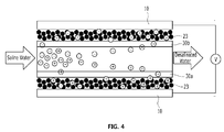
- a capacitive deionization apparatus that includes, as shown in FIGS. 4 and 5 , an ion exchange membrane 30(including a cation exchange membrane 30a and an anion exchange membrane 30b) arranged between a pair of the electrodes 10 to let ions pass through in a selective manner; and a graphene slurry 23 may continuously flow in the flow channel provided between the electrodes 10 and the ion exchange membrane 30 to remove ionic substances from the feed solution by adsorption.
- the electrodes 10 and the ion exchange membrane 30 form a flow channel in which the graphene slurry 23 flows, so the graphene can flow in the flow channel while fluidized as a mixture with an electrolyte or the like.
- the electrode material or the electrode active material is immobilized, so it needs to increase the size of the electrode in order to secure a capacity required to a charging/discharging.
- the electrode active material can be supplied continuously, making it possible to freely change the design of the apparatus according to the use purpose without a limitation in the size or space.
- the width of the flow channel between the electrode 10 and the ion exchange membrane 30 can be changed without a limitation due to the size. Also, the charging/discharging efficiency can be enhanced simply by changing the fluid velocity of the graphene slurry 23 or imposing a limit on the width ratio of a flow channel for active material to a flow channel for feed solution.
- a single unit of the capacitive deionization apparatus or a set of multiple capacitive deionization apparatuses may be in operation. Further, the individual capacitive deionization apparatuses constituting the set may be operated according to a different operating schedule from one another to perform a charging and discharging in an alternate manner, thereby achieving a continuous desalinization of the influent solution.
- the set may consist of two capacitive deionization apparatuses, as illustrated in FIG. 5 , where the two capacitive deionization apparatuses perform a charging and a discharging in an alternate manner so that the graphene slurry 23 circulates between the two capacitive deionization apparatuses to realize a successive operation of the two capacitive deionization apparatuses.
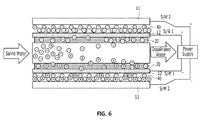
- a capacitive deionization apparatus that includes, as shown in FIGS. 6 and 7 , a pair of first electrodes 11; and a pair of second electrodes 12 having a graphene deposition layer 20 formed on the surface of the flow channel having the feed solution flowing therein.
- the second electrodes 12 are arranged between the first electrodes 11, and an active slurry 40 is put between the first and second electrodes 11 and 12.
- the ionic substances included in the feed solution are adsorbed onto the second electrodes 12 on which the graphene deposition layer 20 is formed. Passing through the second electrodes 12, the adsorbed ionic substances move to the first electrodes 11 and become adsorbed onto the first electrodes 11.
- the second electrodes 12 are preferably porous electrodes so that the ionic substances are allowed to pass through the second electrodes.
- the active slurry 40 made up of an electrode active material is put between the first electrode 11 and the second electrode 12 to further enhance the ion adsorption capacity.
- the active slurry 40 also serves to connect the first electrode 11 and the second electrode 12 together and reduce the electric resistance between the electrodes.
- the active slurry 40 may be selected from various materials capable of acting as an electrode active material.
- the active slurry may be a carbon slurry, a graphene slurry, or a conductive nanoparticle slurry.
- the charging and discharging of the first and second electrodes 11 and 12 may be performed in a simultaneous or alternate manner under necessary, as shown in FIGS. 6 and 7 .
- the above-described exemplary embodiments introduce a graphene material with high efficiency and high adsorption capacity in different forms to the existing electrodes, making it possible to realize a CDI apparatus easy to make with large capacity and applicable to water with high salt concentration.
- a capacitive deionization apparatus that has a feed solution flowing between a pair of electrodes 10 to remove ionic substances from the feed solution by adsorption, where a cation exchange resin 51 and an anion exchange resin 52 are mixed together and put into the flow channel between the electrodes 10 in order to enhance the removal efficiency of the ionic substances.
- the CDI or MCDI of the related art is generally designed to provide an ion exchange membrane and design the flow channel so narrow as much as about 100 ⁇ m, as shown in FIG. 8 , in order to increase the deionization efficiency. But, in the CDI or MCDI of the related art, such a narrow flow channel is likely to cause the fouling effect and reduce the water throughput. Further, the whole system comes to a halt when the narrow flow channel is plugged up, making it difficult to make a large-area serial CDI module and thus leading to a limitation to enhance the productivity in desalination of water on large scale.
- the present invention can reduce the electric resistance in the flow channel by increasing the size of the flow channel and also filling the flow channel with the cation exchange resin 51 and the anion exchange resin 52 to function as a bridge.
- the capacitive deionization apparatus of the present invention increases the size of the flow channel to reduce the fouling effect and increase the throughput of water and also uses the cation exchange resin 51 and the anion exchange resin 52 put into the flow channel to raise the deionization efficiency and enhance the salt removal rate during the desalination.
- the capacitive deionization apparatus of the present invention uses an ion exchange resin, which is relatively cheap, so it can dramatically reduce the CAPEX cost by eliminating the need of using an expensive ion exchange membrane that is used to enhance the deionization efficiency in the capacitive deionization apparatus of the related art.
- the thickness of the flow channel formed between the electrodes 10 can be changed in a wide range under necessary and is preferably in the range of 0.2 mm to 10 mm in order to reduce the fouling effect and increase the water throughput.
- the flow channel is too thin, it is likely to cause problems such as the fouling effect or the like as in the capacitive deionization apparatus of the related art.
- the flow channel is too thick, it leads to deterioration in the deionization efficiency.
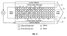
- the cation exchange resin 51 and the anion exchange resin 52 put into the flow channel between the electrodes 10 may be uniformly mixed together, as shown in FIG. 9 .
- the cation exchange resin 51 and the anion exchange resin 52 may have an opposite concentration gradient to each other in order to further enhance the deionization efficiency.
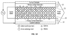
- the cation exchange resin 51 is mostly distributed on the side of the cathode rather than the anode, whereas the anion exchange resin 52 is mostly distributed on the side of the anode rather than the cathode.
- the cation exchange resin 51 and the anion exchange resin 52 are distributed uniformly in the center of the flow channel.
- a parallel capacitive deionization apparatus has a high-voltage, high-current structure that divides a voltage a little at a time into the individual cells.
- the parallel capacitive deionization apparatus has a high removal efficiency but a short removal time.
- a serial capacitive deionization apparatus has a high-voltage, low-current structure that applies a voltage to the entire electrodes.
- the serial capacitive deionization apparatus has a low initial removal efficiency but a long removal time and secures a reduced cost and high energy efficiency in association with the size-expansion of the module.
- serial capacitive deionization apparatus takes over the parallel CDI module in terms of price competition, for it uses a power supply and a control system relatively cheap and requires no SMPS (Switching Mode Power Supply).
- the present invention can realize a large-area serial capacitive deionization apparatus by expanding the flow channel and filling it with an ion exchange resin.
- the serial capacitive deionization apparatus of the present invention includes an electrode 10 and an ion exchange resin 50 sequentially stacked as shown in FIG. 13 , so that a voltage is applied to the whole electrodes, and a cation exchange resin 51 and an anion exchange resin 52 are mixed together and put into each flow channel between the adjacent electrodes 10.
- This structure can achieve desalination of water on large area and large scale without plugging up the flow channels.
- the thickness of the flow channel formed between the electrodes 10 can be changed in a wide range under necessary and is preferably in the range of 0.2 mm to 10 mm in order to reduce the fouling effect and increase the water throughput.
- the flow channel is too thin, it is likely to cause problems such as the fouling effect or the like as in the capacitive deionization apparatus of the related art.
- the flow channel is too thick, it leads to a deterioration in the deionization efficiency.
- the cation exchange resin 51 and the anion exchange resin 52 put into the flow channel between the electrodes 10 may be uniformly mixed together.
- the cation exchange resin 51 and the anion exchange resin 52 may have an opposite concentration gradient to each other in order to further enhance the deionization efficiency as described above.
- the cation exchange resin 51 is mostly distributed on the side of the cathode rather than the anode, whereas the anion exchange resin 52 is mostly distributed on the side of the anode rather than the cathode.
- the cation exchange resin 51 and the anion exchange resin 52 are distributed uniformly in the center of the flow channel.
- the above-described embodiments can realize a CDI apparatus designed to minimize the fouling effect and increase the water throughput with enhanced removal efficiency for ionic substances.
- a deionization system that includes: a serial capacitive deionization apparatus of the present invention; a water tank for feeding water to the serial capacitive deionization apparatus; a power supply for supplying power to the first and second electrodes of the serial capacitive deionization apparatus; and a deionized water tank for storing deionized water from the serial capacity deionization apparatus.
Landscapes
- Chemical & Material Sciences (AREA)
- Chemical Kinetics & Catalysis (AREA)
- Water Supply & Treatment (AREA)
- Engineering & Computer Science (AREA)
- Health & Medical Sciences (AREA)
- Life Sciences & Earth Sciences (AREA)
- Analytical Chemistry (AREA)
- Hydrology & Water Resources (AREA)
- General Chemical & Material Sciences (AREA)
- Electrochemistry (AREA)
- Environmental & Geological Engineering (AREA)
- Molecular Biology (AREA)
- Organic Chemistry (AREA)
- Urology & Nephrology (AREA)
- Water Treatment By Electricity Or Magnetism (AREA)
- Separation Using Semi-Permeable Membranes (AREA)
Abstract
Description
- This application claims priority from
Korean Application No. 10-2015-0062547, filed May 04, 2015 Korean Application No. 10-2015-0124339, filed September 02, 2015 - Apparatuses and methods consistent with exemplary embodiments relate to a capacitive deionization apparatus and a method for manufacturing the same, which capacitive deionization apparatus is enhanced in the removal efficiency for ionic substances and the fluid throughput, hence applicable to water with high salt concentration such as sea water, etc., and easy to manufacture.
- Capacitive deionization (CDI) is a technology directed to removing water of ionic substances by using the adsorption and desorption of ions in the electric double layer (EDL) formed at a charged electrode interface.
-
FIG. 1 is a diagram showing the principle of the CDI technique, illustrating the process of ion adsorption and desorption on the surface of charged electrodes. Referring toFIG. 1 , upon applying a voltage at a potential difference range that does not incur electrolysis of water, the electrodes are charged with a defined quantity of electric charge. As a stream of brine water containing ions flows through the charged electrodes, the counter-ions having the opposite charge sign to the one in the charged electrodes move to each electrode by the electrostatic force and become adsorbed from the water onto the surface of the electrodes, and the water passing through the electrodes turns to desalinated water that is free from ions. - In this regard, the quantity of ions adsorbed onto the electrodes depends on the capacitance of the electrodes in use. Thus, the electrodes as used in the CDI are generally porous carbon electrodes with a large specific surface area.
- When the electrodes are saturated with the ions beyond their adsorption capacity, theelectrodes cannot adsorb ions any more and the ions of the influent stream become stuck in the effluent stream. In order to release the ions adsorbed by the electrodes, a short-circuit potential or an opposite electric potential to the adsorption one is applied to the electrodes. This causes the electrodes to lose electric charges or get counter charges, and the adsorbed ions are rapidly released from the electrodes, leading to a regeneration of the electrodes.
- In this manner, the CDI technique is very easy to operate, for the technique involves adsorption and desorption of ions triggered merely by changing the electric potential of the electrodes. Further, the CDI causes no emission of environmental pollutants during the deionization, so it is thus known as an eco-friendly deionization process. As an example of the improved CDI, the membrane capacitive deionization (MCDI) device includes an ion exchange membrane formed on the surface of the electrodes in order to increase the selectivity for ions to adsorb.
- However, the CDI or MCDI electrodes of the related art, which are made up of a stationary active material (e.g., activated carbon, carbon fiber, carbon aerogel, etc.), have a limitation in the ion adsorption performance. In order to secure a large adsorption capacity, it is necessary to expand the electrodes to a large area or to stack multiple electrodes.However, the above-described expansion of the electrodes can cause a great increase in the costs for the manufacture and operation of the related equipment in need.
- Accordingly, many attempts have been made to use a novel material with high ion adsorption performance as an electrode material. Such methods, however, not only require a complicated process for the manufacture of electrodes but also have a limitation in maximizing the surface area of the novel material due to formability, density, etc.
- In the CDI or MCDI of the related art, it is common to design the flow channel so narrow as much as about 100 µm in order to increase the deionization efficiency. Such a narrow flow channel is susceptible to heavy fouling, reducing the water throughput and deteriorating the productivity. Further, the narrow flow channel makes it difficult to make a serial capacitive deionization (CDI) module with large area, leading to a limitation in raising the productivity.
- Particularly, when increasing the water throughput for the sake of commercialization in the CDI or MCDI of the related art, it is necessary to assemble a plurality of unit cells required to realize a defined capacity. This can deteriorate the productivity and also increase the volume of the apparatus, causing a limitation in the mobility of the apparatus. In addition, the capacitive deionization (CDI) apparatus of the related art possibly causes the channeling effect on the surface of the electrodes in the stack depending on the influent and effluent positions of the fluid and thus deteriorates the ion removal efficiency.
- One or more exemplary embodiments provide a capacitive deionization apparatus and a method for manufacturing the same, where the capacitive deionization apparatus is available to have high capacity, applicable to water with high salt concentration and easy to manufacture.
- One or more exemplary embodiments also provide a capacitive deionization apparatus and a method for manufacturing the same, where the capacitive deionization apparatus is simplified in the construction and capable of realizing optimum energy efficiency.
- In accordance with an aspect of an exemplary embodiment, there is provided a capacitive deionization apparatus, which has a feed solution passing between a pair of
electrodes 10 to remove ionic substances from the feed solution through adsorption by the electrostatic force, the capacitive deionization apparatus including: graphene contained in an electrode material or an electrode active material; or acation exchange resin 51 and ananion exchange resin 52 mixed together and put into a flow channel between theelectrodes 10 without an ion exchange membrane. - In an exemplary embodiment, the capacitive deionization apparatus may further include an
ion exchange membrane 30 arranged between theelectrodes 10 to let ions pass through in a selective manner, and a mesh-like graphene 22 may be put between theelectrodes 10 and theion exchange membrane 30. - In an exemplary embodiment, the capacitive deionization apparatus may further include an
ion exchange membrane 30 arranged between theelectrodes 10 to let ions pass through in a selective manner, and agraphene slurry 23 may continuously flow in the flow channel between theelectrodes 10 and theion exchange membrane 30 to remove ionic substances from the feed solution by adsorption. - In an exemplary embodiment, the capacitive deionization apparatus may include a pair of
first electrodes 11; and a pair ofsecond electrodes 12 being arranged between thefirst electrodes 11 and having agraphene deposition layer 20 formed on the surface of the flow channel having the feed solution flowing therein. - In an exemplary embodiment, an
active slurry 40 may be put between the first andsecond electrodes first electrode 11 or thesecond electrode 12 may be a porous electrode. - In an exemplary embodiment, the
active slurry 40 may be a carbon slurry, a graphene slurry, or a conductive nanoparticle slurry. - In an exemplary embodiment, the charging and discharging of the first and
second electrodes - In an exemplary embodiment, the thickness of the flow channel formed between the
electrodes 10 may be in the range of 0.2 mm to 10 mm. - In an exemplary embodiment, the
cation exchange resin 51 and theanion exchange resin 52 put into the flow channel between the electrodes may have an opposite concentration gradient to each other. Thecation exchange resin 51 may be mostly distributed on the side of a cathode, and theanion exchange resin 52 may be mostly distributed on the side of an anode. - In an exemplary embodiment, the
cation exchange resin 51 and theanion exchange resin 52 may be distributed uniformly in the center of the flow channel. - In an exemplary embodiment, the capacitive deionization apparatus may be constructed as a serial capacitive deionization apparatus that includes an
ion exchange resin 20 and anelectrode 10 sequentially stacked between a pair ofelectrodes 10, with a voltage applied to the whole electrodes. Thecation exchange resin 51 and theanion exchange resin 52 may be mixed together and put into each flow channel between theadjacent electrodes 10 without an ion exchange membrane. - In an exemplary embodiment, the
cation exchange resin 51 and theanion exchange resin 52 put into the flow channel between theadjacent electrodes 10 may have an opposite concentration gradient to each other. Thecation exchange resin 51 may be mostly distributed on the side of a cathode, and theanion exchange resin 52 may be mostly distributed on the side of an anode. - In accordance with an aspect of another exemplary embodiment, there is provided a capacitive deionization apparatus including: a pair of electrodes between which a feed solution passes through to remove ionic substances from the feed solution through adsorption by electrostatic force; and graphene or a cation exchange resin and an anion exchange resin mixed together, the cation and the anion exchange resins provided in a flow channel between the pair of electrodes.
- The capacitive deionization apparatus may further include an ion exchange membrane arranged between the pair of electrodes, wherein mesh-like graphene is provided between a first electrode of the pair electrodes and an ion exchange membrane.
- The capacitive deionization apparatus may further include an ion exchange membrane arranged between the pair of electrodes, wherein a graphene slurry continuously flows in the flow channel between a first electrode of the electrodes and an ion exchange membrane to remove the ionic substances from the feed solution through the adsorption.
- A continuous operation method of capacitive deionization apparatuses, the method including: providing a plurality of capacitive deionization apparatuses as a set, wherein the plurality of capacitive deionization apparatuses constituting the set are configured to operate according to a different operating schedule from one another to perform a charging and discharging in an alternate manner, thereby achieving a continuous desalinization of an influent solution.
- The set may include two capacitive deionization apparatuses, wherein the two capacitive deionization apparatuses perform a charging and a discharging in an alternate manner so that graphene slurry circulates between the two capacitive deionization apparatuses.
- The pair of electrodes may include: a pair of first electrodes; and a pair of second electrodes being arranged between the pair of first electrodes and comprising a graphene deposition layer formed on a surface of the flow channel having the feed solution flowing therein.
- An active slurry may be provided between the first and the second electrodes.
- One of the first electrodes or one of the second electrodes may be a porous electrode.
- The active slurry may include a carbon slurry, a graphene slurry, or a conductive nanoparticle slurry.
- The first and the second electrodes may be configured to charge and discharge in a simultaneous or alternate manner from each other.
- A thickness of the flow channel formed between the pair of electrodes may be in a range between 0.2 mm and 10 mm.
- The cation exchange resin and the anion exchange resin provided into the flow channel between the pair of electrodes may have an opposite concentration gradient from each other.
- The cation exchange resin may be provided on a cathode side, and the anion exchange resin is provided on an anode side.
- The cation exchange resin and the anion exchange resin may be distributed uniformly in a center portion of the flow channel.
- The capacitive deionization apparatus may include a serial capacitive deionization apparatus comprising an ion exchange resin and an electrode sequentially stacked between a pair of electrodes, with a voltage applied to the pair of electrodes, wherein the cation exchange resin and the anion exchange resin are mixed together and provided in each flow channel between the adjacent electrodes.
- The graphene may be contained in an electrode material or an electrode active material.
- The capacitive deionization apparatus of the present invention introduces a graphene material with high-efficiency adsorption performance in a variety of forms to the electrodes or uses an ion exchange resin put in the flow channels. This makes it easy to construct the apparatus with large capacity and renders the apparatus applicable to water with high salt concentration. Further, the capacitive deionization apparatus of the present invention can increase the size of the flow channels to minimize the fouling effect and promote the water throughput and also enhance the deionization efficiency to reduce the CAPEX cost.
- The advantageous effects of the present invention are not limited to the above-mentioned effects and may be construed to include all the effects deducible from the construction of the present invention as disclosed in the detailed description or the claims of the present invention.
-
-
FIG. 1 is a diagram illustrating the principle of the capacitive deionization (CDI) technique. -
FIGS. 2 and3 are conceptual schemes showing the construction and the operating mechanism of a capacitive deionization apparatus using a mesh-like graphene in accordance with one embodiment of the present invention. -
FIGS. 4 and5 are conceptual schemes showing the construction and the operating mechanism of a capacitive deionization apparatus using a graphene slurry in accordance with one embodiment of the present invention. -
FIGS. 6 and7 are conceptual schemes showing the construction and the operating mechanism of a capacitive deionization apparatus using two types of electrodes in accordance with one embodiment of the present invention. -
FIG. 8 is a conceptual scheme showing the construction and the operating mechanism of a conventional MCDI apparatus. -
FIGS. 9 and10 are conceptual schemes showing the construction and the operating mechanism of a capacitive deionization apparatus having flow channels filled with an ion exchange resin in accordance with one embodiment of the present invention. -
FIGS. 11 and12 are conceptual schemes showing the construction and the operating mechanism of parallel and serial CDI systems. -
FIG. 13 is a conceptual scheme showing the construction and the operating mechanism of a serial capacitive deionization apparatus having flow channels filled with an ion exchange resin in accordance with one embodiment of the present invention. -
10: Electrode 11: First electrode 12: Second electrode 22: Mesh-like graphene 23: Graphene slurry 30: Ion exchange membrane 30a: Cation exchange membrane 30b: Anion exchange membrane 40: Active slurry 50: Ion exchange resin 51: Cation exchange resin 52: Anion exchange resin - Reference will now be made in detail to exemplary embodiments of the disclosure with reference to the attached drawings. It will be understood that words or terms used in the specification and claims shall not be interpreted as the meaning defined in commonly used dictionaries. It will be further understood that the words or terms should be interpreted as having a meaning that is consistent with their meaning in the context of the relevant art and the technical idea of the disclosure.
- In accordance with an exemplary embodiment of the present invention, there is provided a capacitive deionization apparatus that has a feed solution flowing between a pair of
electrodes 10 to remove ionic substances from the feed solution by adsorption, where the capacitive deionization apparatus uses graphene as an electrode material or an electrode active material in order to enhance the adsorption performance of theelectrodes 10. Hereinafter, a detailed description will be given as to the embodiment of the present invention with reference to the accompanying drawings. - Graphene, a thin film-like nano-scale material made up of carbon atoms arranged in the form of a honeycomb lattice, can enhance the ion adsorption performance of CDI electrodes due to its high porosity. But, using graphene in the manufacture of CDI electrodes requires many processes and high cost in forming the graphene of a defined shape and density of a defined level or above.
- For this reason, the exemplary embodiment of the present invention involves forming a graphene deposition layer on the surface of an electrode. The graphene deposition layer may be produced by different methods, including mechanical or chemical exfoliation of graphite, epitaxial growth on a silicone carbide substrate, chemical vapor deposition on a transition metal catalyst layer, or the like.
- The chemical vapor deposition (CVD) for graphene synthesis is a method which includes heating a metal thin film at high temperature in the hydrocarbon atmosphere for pyrolysis of a hydrocarbon gas, melting the decomposed carbon atoms into the metal thin film and then performing a cooling to cause segregation of supersaturated carbon atoms on the surface of the metal thin film and thereby to create a graphene layer on the metal thin film.
- In accordance with an exemplary embodiment of the present invention, there is provided a capacitive deionization apparatus that includes, as shown in
FIGS. 2 and3 , anion exchange membrane 30 arranged between a pair of theelectrodes 10 to let ions pass through in a selective manner, where a mesh-like graphene 22 may be put between theelectrode 10 and theion exchange membrane 30. As shown inFIGS. 2 and3 , theion exchange membrane 30 may include acation exchange membrane 30a and ananion exchange membrane 30b. Hereinafter, the cation and theanion exchange membranes ion exchange membrane 30. - For this, the capacitive deionization apparatus of the present invention may further include a metal thin film between the
electrode 10 and the graphene deposition layer 20(SeeFIGS. 6 and7 ), or construct theelectrode 10 using a metal layer. In addition, anion exchange membrane 30 used to enhance the selectivity of ions adsorbed onto the surface of the electrode may be employed under necessity or omitted. - The mesh-
like graphene 22 provided between theelectrode 10 and theion exchange membrane 30 may use the existing electrode to enhance the ion adsorption performance. Theelectrode 10 and theion exchange membrane 30 may be connected to each other to reduce the electric resistance between the electrode and the membrane. The mesh-like grapheme 22 is prepared by different methods and capable of realizing the larger surface area and the higher ion adsorption performance than the thin film-type graphene. - In accordance with an exemplary embodiment of the present invention, there is provided a capacitive deionization apparatus that includes, as shown in
FIGS. 4 and5 , an ion exchange membrane 30(including acation exchange membrane 30a and ananion exchange membrane 30b) arranged between a pair of theelectrodes 10 to let ions pass through in a selective manner; and agraphene slurry 23 may continuously flow in the flow channel provided between theelectrodes 10 and theion exchange membrane 30 to remove ionic substances from the feed solution by adsorption. - The
electrodes 10 and theion exchange membrane 30 form a flow channel in which thegraphene slurry 23 flows, so the graphene can flow in the flow channel while fluidized as a mixture with an electrolyte or the like. - In the related art, the electrode material or the electrode active material is immobilized, so it needs to increase the size of the electrode in order to secure a capacity required to a charging/discharging. However, when using the
graphene slurry 23 as in the exemplary embodiment of the present invention, the electrode active material can be supplied continuously, making it possible to freely change the design of the apparatus according to the use purpose without a limitation in the size or space. - As a continuous supply of the
graphene slurry 23 is secured, the width of the flow channel between theelectrode 10 and theion exchange membrane 30 can be changed without a limitation due to the size. Also, the charging/discharging efficiency can be enhanced simply by changing the fluid velocity of thegraphene slurry 23 or imposing a limit on the width ratio of a flow channel for active material to a flow channel for feed solution. - On the other hand, a single unit of the capacitive deionization apparatus or a set of multiple capacitive deionization apparatuses may be in operation. Further, the individual capacitive deionization apparatuses constituting the set may be operated according to a different operating schedule from one another to perform a charging and discharging in an alternate manner, thereby achieving a continuous desalinization of the influent solution.
- In a specific exemplary embodiment, the set may consist of two capacitive deionization apparatuses, as illustrated in
FIG. 5 , where the two capacitive deionization apparatuses perform a charging and a discharging in an alternate manner so that thegraphene slurry 23 circulates between the two capacitive deionization apparatuses to realize a successive operation of the two capacitive deionization apparatuses. - In accordance with further another exemplary embodiment of the present invention, there is provided a capacitive deionization apparatus that includes, as shown in
FIGS. 6 and7 , a pair offirst electrodes 11; and a pair ofsecond electrodes 12 having agraphene deposition layer 20 formed on the surface of the flow channel having the feed solution flowing therein. Thesecond electrodes 12 are arranged between thefirst electrodes 11, and anactive slurry 40 is put between the first andsecond electrodes - In the exemplary embodiment, two different pairs of electrodes are used in order to maximize the surface area and the absorption performance. To describe the process in detail, the ionic substances included in the feed solution are adsorbed onto the
second electrodes 12 on which thegraphene deposition layer 20 is formed. Passing through thesecond electrodes 12, the adsorbed ionic substances move to thefirst electrodes 11 and become adsorbed onto thefirst electrodes 11. In this regard, thesecond electrodes 12 are preferably porous electrodes so that the ionic substances are allowed to pass through the second electrodes. - The
active slurry 40 made up of an electrode active material is put between thefirst electrode 11 and thesecond electrode 12 to further enhance the ion adsorption capacity. In this case, theactive slurry 40 also serves to connect thefirst electrode 11 and thesecond electrode 12 together and reduce the electric resistance between the electrodes. Theactive slurry 40 may be selected from various materials capable of acting as an electrode active material. In an exemplary embodiment, the active slurry may be a carbon slurry, a graphene slurry, or a conductive nanoparticle slurry. - Further, the charging and discharging of the first and
second electrodes FIGS. 6 and7 . - The above-described exemplary embodiments introduce a graphene material with high efficiency and high adsorption capacity in different forms to the existing electrodes, making it possible to realize a CDI apparatus easy to make with large capacity and applicable to water with high salt concentration.
- In accordance with further an exemplary embodiment of the present invention, there is provided a capacitive deionization apparatus that has a feed solution flowing between a pair of
electrodes 10 to remove ionic substances from the feed solution by adsorption, where acation exchange resin 51 and ananion exchange resin 52 are mixed together and put into the flow channel between theelectrodes 10 in order to enhance the removal efficiency of the ionic substances. Hereinafter, a detailed description will be given as to the exemplary embodiment of the present invention with reference to the accompanying drawings. - The CDI or MCDI of the related art is generally designed to provide an ion exchange membrane and design the flow channel so narrow as much as about 100 µm, as shown in
FIG. 8 , in order to increase the deionization efficiency. But, in the CDI or MCDI of the related art, such a narrow flow channel is likely to cause the fouling effect and reduce the water throughput. Further, the whole system comes to a halt when the narrow flow channel is plugged up, making it difficult to make a large-area serial CDI module and thus leading to a limitation to enhance the productivity in desalination of water on large scale. - In order to maintain the deionization efficiency and solve the problems in association with the fouling effect and the reduced water throughput, the present invention can reduce the electric resistance in the flow channel by increasing the size of the flow channel and also filling the flow channel with the
cation exchange resin 51 and theanion exchange resin 52 to function as a bridge. - In other words, the capacitive deionization apparatus of the present invention increases the size of the flow channel to reduce the fouling effect and increase the throughput of water and also uses the
cation exchange resin 51 and theanion exchange resin 52 put into the flow channel to raise the deionization efficiency and enhance the salt removal rate during the desalination. - In addition, the capacitive deionization apparatus of the present invention uses an ion exchange resin, which is relatively cheap, so it can dramatically reduce the CAPEX cost by eliminating the need of using an expensive ion exchange membrane that is used to enhance the deionization efficiency in the capacitive deionization apparatus of the related art.
- In this regard, the thickness of the flow channel formed between the
electrodes 10 can be changed in a wide range under necessary and is preferably in the range of 0.2 mm to 10 mm in order to reduce the fouling effect and increase the water throughput. When the flow channel is too thin, it is likely to cause problems such as the fouling effect or the like as in the capacitive deionization apparatus of the related art. When the flow channel is too thick, it leads to deterioration in the deionization efficiency. - The
cation exchange resin 51 and theanion exchange resin 52 put into the flow channel between theelectrodes 10 may be uniformly mixed together, as shown inFIG. 9 . Alternatively, thecation exchange resin 51 and theanion exchange resin 52 may have an opposite concentration gradient to each other in order to further enhance the deionization efficiency. - More specifically, as shown in
FIG. 10 , thecation exchange resin 51 is mostly distributed on the side of the cathode rather than the anode, whereas theanion exchange resin 52 is mostly distributed on the side of the anode rather than the cathode. This not only maximizes the adsorption efficiency in each electrode but also helps the desorbed ions released rapidly by the ion exchange resin and the flux when the power is off. Preferably, thecation exchange resin 51 and theanion exchange resin 52 are distributed uniformly in the center of the flow channel. - By expanding the flow channel in the capacitive deionization apparatus of the present invention, it is possible to manufacture a serial capacitive deionization apparatus that is difficult to realize in the prior art due to the narrow flow channel.
- As illustrated in
FIGS. 11 and12 , a parallel capacitive deionization apparatus has a high-voltage, high-current structure that divides a voltage a little at a time into the individual cells. The parallel capacitive deionization apparatus has a high removal efficiency but a short removal time. In contrast, a serial capacitive deionization apparatus has a high-voltage, low-current structure that applies a voltage to the entire electrodes. The serial capacitive deionization apparatus has a low initial removal efficiency but a long removal time and secures a reduced cost and high energy efficiency in association with the size-expansion of the module. - In addition, the serial capacitive deionization apparatus takes over the parallel CDI module in terms of price competition, for it uses a power supply and a control system relatively cheap and requires no SMPS (Switching Mode Power Supply).
- In the capacitive deionization apparatus of the related art, the whole system comes to a halt upon the narrow flow channel plugged up, making it difficult to make a large-area serial CDI module.
- The present invention can realize a large-area serial capacitive deionization apparatus by expanding the flow channel and filling it with an ion exchange resin. More specifically, the serial capacitive deionization apparatus of the present invention includes an
electrode 10 and an ion exchange resin 50 sequentially stacked as shown inFIG. 13 , so that a voltage is applied to the whole electrodes, and acation exchange resin 51 and ananion exchange resin 52 are mixed together and put into each flow channel between theadjacent electrodes 10. This structure can achieve desalination of water on large area and large scale without plugging up the flow channels. - In this regard, the thickness of the flow channel formed between the
electrodes 10 can be changed in a wide range under necessary and is preferably in the range of 0.2 mm to 10 mm in order to reduce the fouling effect and increase the water throughput. When the flow channel is too thin, it is likely to cause problems such as the fouling effect or the like as in the capacitive deionization apparatus of the related art. When the flow channel is too thick, it leads to a deterioration in the deionization efficiency. - The
cation exchange resin 51 and theanion exchange resin 52 put into the flow channel between theelectrodes 10 may be uniformly mixed together. Alternatively, thecation exchange resin 51 and theanion exchange resin 52 may have an opposite concentration gradient to each other in order to further enhance the deionization efficiency as described above. - More specifically, as shown in
FIG. 13 , thecation exchange resin 51 is mostly distributed on the side of the cathode rather than the anode, whereas theanion exchange resin 52 is mostly distributed on the side of the anode rather than the cathode. This not only maximizes the adsorption efficiency in each electrode but also helps the desorbed ions released rapidly by the ion exchange resin and the flux when the power is off. Preferably, thecation exchange resin 51 and theanion exchange resin 52 are distributed uniformly in the center of the flow channel. - The above-described embodiments can realize a CDI apparatus designed to minimize the fouling effect and increase the water throughput with enhanced removal efficiency for ionic substances.
- In accordance with still further another embodiment of the present invention, there is provided a deionization system that includes: a serial capacitive deionization apparatus of the present invention; a water tank for feeding water to the serial capacitive deionization apparatus; a power supply for supplying power to the first and second electrodes of the serial capacitive deionization apparatus; and a deionized water tank for storing deionized water from the serial capacity deionization apparatus.
- Further, the embodiments discussed have been presented by way of example only and not limitation. Thus, the breadth and scope of the invention(s) should not be limited by any of the above-described exemplary embodiments, but should be defined only in accordance with the following claims and their equivalents. Moreover, the above advantages and features are provided in described embodiments, but shall not limit the application of the claims to processes and structures accomplishing any or all of the above advantages.
- Additionally, the section headings herein are provided for consistency with the suggestions under 37 CFR 1.77 or otherwise to provide organizational cues. These headings shall not limit or characterize the invention(s) set out in any claims that may issue from this disclosure. Specifically and by way of example, although the headings refer to a "Technical Field," the claims should not be limited by the language chosen under this heading to describe the so-called technical field. Further, a description of a technology in the "Background" is not to be construed as an admission that technology is prior art to any invention(s) in this disclosure. Neither is the "Brief Summary" to be considered as a characterization of the invention(s) set forth in the claims found herein. Furthermore, any reference in this disclosure to "invention" in the singular should not be used to argue that there is only a single point of novelty claimed in this disclosure. Multiple inventions may be set forth according to the limitations of the multiple claims associated with this disclosure, and the claims accordingly define the invention(s), and their equivalents, that are protected thereby. In all instances, the scope of the claims shall be considered on their own merits in light of the specification, but should not be constrained by the headings set forth herein.
Claims (15)
- A capacitive deionization apparatus, comprising:a pair of electrodes 10 between which a feed solution passes through to remove ionic substances from the feed solution through adsorption by electrostatic force; andgraphene ora cation exchange resin 51 and an anion exchange resin 52 mixed together, the cation and the anion exchange resins provided in a flow channel between the pair of electrodes 10.
- The capacitive deionization apparatus as claimed in claim 1, further comprising:an ion exchange membrane 30 arranged between the pair of electrodes 10, wherein mesh-like graphene 22 is provided between a first electrode of the pair electrodes 10 and an ion exchange membrane 30.
- The capacitive deionization apparatus as claimed in claim 1, further comprising:an ion exchange membrane 30 arranged between the pair of electrodes 10, wherein a graphene slurry 23 continuously flows in the flow channel between a first electrode of the electrodes 10 and an ion exchange membrane 30 to remove the ionic substances from the feed solution through the adsorption.
- The capacitive deionization apparatus as claimed in claim 1, wherein the pair of electrodes comprises:a pair of first electrodes 11; anda pair of second electrodes 12 being arranged between the pair of first electrodes 11 and comprising a graphene deposition layer 20 formed on a surface of the flow channel having the feed solution flowing therein.
- The capacitive deionization apparatus as claimed in claim 4, wherein an active slurry 40 is provided between the first and the second electrodes 11 and 12.
- The capacitive deionization apparatus as claimed in claim 4, wherein one of the first electrodes 11 or one of the second electrodes 12 is a porous electrode.
- The capacitive deionization apparatus as claimed in claim 5, wherein the active slurry 40 comprises a carbon slurry, a graphene slurry, or a conductive nanoparticle slurry.
- The capacitive deionization apparatus as claimed in claim 4, wherein the first and the second electrodes are configured to charge and discharge in a simultaneous or alternate manner from each other.
- The capacitive deionization apparatus as claimed in claim 1, wherein a thickness of the flow channel formed between the pair of electrodes 10 is in a range between 0.2 mm and 10 mm.
- The capacitive deionization apparatus as claimed in claim 1, wherein the cation exchange resin 51 and the anion exchange resin 52 provided into the flow channel between the pair of electrodes 10 have an opposite concentration gradient from each other.
- The capacitive deionization apparatus as claimed in claim 10, wherein the cation exchange resin 51 is provided on a cathode side, and the anion exchange resin 52 is provided on an anode side.
- The capacitive deionization apparatus as claimed in claim 11, wherein the cation exchange resin 51 and the anion exchange resin 52 are distributed uniformly in a center portion of the flow channel.
- The capacitive deionization apparatus as claimed in claim 1, wherein the capacitive deionization apparatus comprises a serial capacitive deionization apparatus comprising an ion exchange resin 20 and an electrode 10 sequentially stacked between a pair of electrodes 10, with a voltage applied to the pair of electrodes 10,
wherein the cation exchange resin 51 and the anion exchange resin 52 are mixed together and provided in each flow channel between the adjacent electrodes 10. - The capacitive deionization apparatus as claimed in claim 13, wherein the cation exchange resin 51 and the anion exchange resin 52 provided the flow channel between the adjacent electrodes 10 have an opposite concentration gradient from each other.
- The capacitive deionization apparatus as claimed in claim 14, wherein the cation exchange resin 51 is provided on a cathode side, and the anion exchange resin 52 is provided on an anode side.
Priority Applications (1)
| Application Number | Priority Date | Filing Date | Title |
|---|---|---|---|
| EP17188076.8A EP3272714B8 (en) | 2015-05-04 | 2016-03-10 | Capacitive deionization apparatus |
Applications Claiming Priority (2)
| Application Number | Priority Date | Filing Date | Title |
|---|---|---|---|
| KR1020150062547A KR101710923B1 (en) | 2015-05-04 | 2015-05-04 | Capacitive Deionization Device and Operation Method of it |
| KR1020150124339A KR101788119B1 (en) | 2015-09-02 | 2015-09-02 | Capacitive Deionization Device and Capacitive Deionization Module |
Related Child Applications (1)
| Application Number | Title | Priority Date | Filing Date |
|---|---|---|---|
| EP17188076.8A Division EP3272714B8 (en) | 2015-05-04 | 2016-03-10 | Capacitive deionization apparatus |
Publications (2)
| Publication Number | Publication Date |
|---|---|
| EP3090988A2 true EP3090988A2 (en) | 2016-11-09 |
| EP3090988A3 EP3090988A3 (en) | 2017-01-25 |
Family
ID=55524241
Family Applications (2)
| Application Number | Title | Priority Date | Filing Date |
|---|---|---|---|
| EP17188076.8A Active EP3272714B8 (en) | 2015-05-04 | 2016-03-10 | Capacitive deionization apparatus |
| EP16159655.6A Withdrawn EP3090988A3 (en) | 2015-05-04 | 2016-03-10 | Capacitive deionization apparatus |
Family Applications Before (1)
| Application Number | Title | Priority Date | Filing Date |
|---|---|---|---|
| EP17188076.8A Active EP3272714B8 (en) | 2015-05-04 | 2016-03-10 | Capacitive deionization apparatus |
Country Status (2)
| Country | Link |
|---|---|
| US (1) | US10071922B2 (en) |
| EP (2) | EP3272714B8 (en) |
Cited By (4)
| Publication number | Priority date | Publication date | Assignee | Title |
|---|---|---|---|---|
| CN106396240A (en) * | 2016-12-08 | 2017-02-15 | 重庆理工大学 | Seawater saline ion separator based on principle of pulse transformer and seawater desalting method |
| WO2020055578A1 (en) * | 2018-09-11 | 2020-03-19 | Walsh Kevin Michael | Membrane electrode assemblies for ion concentration gradient devices |
| CN113968603A (en) * | 2020-07-22 | 2022-01-25 | 财团法人工业技术研究院 | Water treatment device and water treatment method |
| CN118724196A (en) * | 2024-06-07 | 2024-10-01 | 中国石油大学(华东) | An ultrasonic enhanced flow electrode capacitive deionization device |
Families Citing this family (12)
| Publication number | Priority date | Publication date | Assignee | Title |
|---|---|---|---|---|
| US11377375B2 (en) * | 2016-08-05 | 2022-07-05 | Doosan Heavy Industries & Construction Co., Ltd | Capacitive deionization electrode module and water treatment apparatus and method capable of saving energy using the same |
| WO2018111936A1 (en) * | 2016-12-12 | 2018-06-21 | Atlantis Technologies | Miniature capacitive deionization devices and related systems and methods |
| CN107487816A (en) * | 2017-08-30 | 2017-12-19 | 河海大学 | A kind of combination unit that membrane capacitance system is automatically controlled using the time relay |
| CN109651552B (en) * | 2017-10-11 | 2021-03-30 | 中国石油化工股份有限公司 | Strong alkaline ternary composite nano inorganic oxide-graphene-ion exchange resin material |
| CN109651619B (en) * | 2017-10-11 | 2021-02-09 | 中国石油化工股份有限公司 | Ternary composite nano inorganic oxide/graphene-ion exchange resin material |
| US10787378B2 (en) | 2018-05-30 | 2020-09-29 | Atlantis Technologies | Spirally wound electric double layer capacitor device and associated methods |
| EP3815763A1 (en) * | 2019-11-01 | 2021-05-05 | I3 Membrane GmbH | Method and apparatus for dc voltage controlled adsorption and desorption on charged membranes |
| CN112928305A (en) * | 2019-12-06 | 2021-06-08 | 北京亿华通科技股份有限公司 | Deionizing device for fuel cell |
| US20230067116A1 (en) * | 2021-08-26 | 2023-03-02 | Robert Bosch Gmbh | Cascading, recirculating water deionization systems |
| US12551849B2 (en) * | 2022-02-07 | 2026-02-17 | Jack C. Gardiner | System and method for reducing the dissolved solids of a non-potable aqueous flow |
| CN116371200A (en) * | 2023-03-13 | 2023-07-04 | 中国科学院青海盐湖研究所 | Impurity removal method for crude chemicals in salt lake based on flow capacitance deionization technology |
| CN118324269B (en) * | 2024-06-13 | 2024-08-27 | 水利部牧区水利科学研究所 | High-salinity wastewater treatment device and treatment method |
Family Cites Families (20)
| Publication number | Priority date | Publication date | Assignee | Title |
|---|---|---|---|---|
| US6284124B1 (en) | 1999-01-29 | 2001-09-04 | United States Filter Corporation | Electrodeionization apparatus and method |
| KR100521628B1 (en) | 2003-05-30 | 2005-10-12 | 웅진코웨이주식회사 | Water purifier having electrodeionization system |
| KR101227853B1 (en) | 2007-05-21 | 2013-01-31 | 삼성전자주식회사 | Water softening apparatus |
| KR101004707B1 (en) | 2009-08-07 | 2011-01-04 | (주) 시온텍 | Capacitive electrode for ion removal and electrolytic cell using the same |
| KR101233295B1 (en) | 2010-08-13 | 2013-02-14 | 한국에너지기술연구원 | Flow-electrode device |
| KR20120030834A (en) | 2010-09-20 | 2012-03-29 | 한국전력공사 | Apparatus for treating water using capacitive deionization |
| US20120186980A1 (en) * | 2011-01-26 | 2012-07-26 | Sundara Ramaprabhu | Methods and systems for separating ions from fluids |
| CN103058425B (en) * | 2011-10-21 | 2015-07-29 | 通用电气公司 | desalination system and method |
| US9272926B2 (en) * | 2011-12-18 | 2016-03-01 | Zhuo Sun | Membrane enhanced deionization capacitor device |
| MY196266A (en) * | 2011-12-29 | 2023-03-24 | Shell Int Research | Method and system for enhancing oil recovery (eor) by injecting treated water into an oil bearing formation |
| US9067811B1 (en) * | 2012-05-25 | 2015-06-30 | Lockheed Martin Corporation | System, method, and control for graphenoid desalination |
| KR101207463B1 (en) | 2012-08-16 | 2012-12-03 | (주) 시온텍 | Manufacturing method of capacitive deionization electrode having ion selectivity |
| KR101442530B1 (en) | 2012-11-07 | 2014-09-26 | 한국에너지기술연구원 | Method for manufacturing organic-inorganic hybrid ion exchange resin and method for manufacturing ion exchange membrane using the same |
| ITPD20120363A1 (en) * | 2012-11-30 | 2014-05-31 | Idropan Dell Orto Depuratori S R L | EQUIPMENT FOR THE PURIFICATION OF A FLUID AND A PURIFICATION METHOD OF A FLUID, IN PARTICULAR THROUGH THE ABOVE EQUIPMENT |
| KR20140119545A (en) | 2013-04-01 | 2014-10-10 | 한국과학기술원 | Capacitive deionization apparatus and deionization system |
| KR101582477B1 (en) | 2013-06-28 | 2016-01-06 | 한국에너지기술연구원 | Capacitive deionization apparatus having conductive foam |
| KR20150008348A (en) | 2013-07-12 | 2015-01-22 | 한국에너지기술연구원 | Hybrid seawater desalination systems |
| ITPD20130280A1 (en) * | 2013-10-09 | 2015-04-10 | Idropan Dell Orto Depuratori S R L | EQUIPMENT FOR THE TREATMENT OF A FLUID |
| KR102211119B1 (en) | 2013-12-23 | 2021-02-04 | 코웨이 주식회사 | Cdi type water treatment apparatus |
| KR101410642B1 (en) | 2014-02-20 | 2014-06-24 | (주) 시온텍 | Manufacturing method of capacitive deionization electrode and capacitive deionization electrode made therefrom and CDI module using the same |
-
2016
- 2016-03-10 EP EP17188076.8A patent/EP3272714B8/en active Active
- 2016-03-10 EP EP16159655.6A patent/EP3090988A3/en not_active Withdrawn
- 2016-03-21 US US15/075,840 patent/US10071922B2/en active Active
Non-Patent Citations (1)
| Title |
|---|
| None |
Cited By (5)
| Publication number | Priority date | Publication date | Assignee | Title |
|---|---|---|---|---|
| CN106396240A (en) * | 2016-12-08 | 2017-02-15 | 重庆理工大学 | Seawater saline ion separator based on principle of pulse transformer and seawater desalting method |
| WO2020055578A1 (en) * | 2018-09-11 | 2020-03-19 | Walsh Kevin Michael | Membrane electrode assemblies for ion concentration gradient devices |
| US11322797B2 (en) | 2018-09-11 | 2022-05-03 | Kevin Michael Walsh | Membrane electrode assemblies for ion concentration gradient devices |
| CN113968603A (en) * | 2020-07-22 | 2022-01-25 | 财团法人工业技术研究院 | Water treatment device and water treatment method |
| CN118724196A (en) * | 2024-06-07 | 2024-10-01 | 中国石油大学(华东) | An ultrasonic enhanced flow electrode capacitive deionization device |
Also Published As
| Publication number | Publication date |
|---|---|
| US10071922B2 (en) | 2018-09-11 |
| EP3272714B1 (en) | 2019-05-15 |
| EP3272714B8 (en) | 2019-07-10 |
| EP3090988A3 (en) | 2017-01-25 |
| EP3272714A1 (en) | 2018-01-24 |
| US20160326025A1 (en) | 2016-11-10 |
Similar Documents
| Publication | Publication Date | Title |
|---|---|---|
| US10071922B2 (en) | Capacitive deionization apparatus and method for manufacturing the same | |
| US10259728B2 (en) | Apparatus and process for separation and selective recomposition of ions | |
| EP3245162B1 (en) | Single module, flow-electrode apparatus and method for continous water desalination and ion separation by capacitive deionization | |
| JP6078074B2 (en) | Desalination system and method | |
| US8652314B2 (en) | Flow de-ionization using independently controlled voltages | |
| US10450661B2 (en) | Electrochemical module configuration for the continuous acidification of alkaline water sources and recovery of CO2 with continuous hydrogen gas production | |
| US20130153426A1 (en) | Membrane enhanced deionization capacitor device | |
| SE540976C2 (en) | Device for capacitive deionization of aqueous media and method of manufacturing such a device | |
| KR101692387B1 (en) | Flow-electrode device with electrode regeneration by short circuit and capacitive deionization device | |
| KR101710923B1 (en) | Capacitive Deionization Device and Operation Method of it | |
| KR101929855B1 (en) | Capacitive Deionization Device and Capacitive Deionization Module | |
| KR102043273B1 (en) | A produced water manufacturing apparatus with deionization cell and produced water manyfacturing method using the same | |
| JP5355460B2 (en) | Electric deionized water production equipment | |
| CN114873698B (en) | Capacitive deionization and water purification device with regenerative electric energy and separation chamber manufacturing method | |
| KR101094731B1 (en) | Electrochemical Water Treatment Device Using Carbon Electrode | |
| EP2810922A1 (en) | Method and device to remove ions from an electrolytic media, such as water desalination, using suspension of divided materials in a flow capacitor | |
| KR101788119B1 (en) | Capacitive Deionization Device and Capacitive Deionization Module | |
| KR102184220B1 (en) | Capacitive deionization type water treatment cell and water treatment apparatus having the same | |
| KR20130121581A (en) | Deionization device | |
| KR101850787B1 (en) | Capacitive deionization apparatus and method for adsorbing ions in feed solution using the same | |
| JP2003039070A (en) | Desalinated water production apparatus and desalinated water production method |
Legal Events
| Date | Code | Title | Description |
|---|---|---|---|
| PUAI | Public reference made under article 153(3) epc to a published international application that has entered the european phase |
Free format text: ORIGINAL CODE: 0009012 |
|
| 17P | Request for examination filed |
Effective date: 20160310 |
|
| AK | Designated contracting states |
Kind code of ref document: A2 Designated state(s): AL AT BE BG CH CY CZ DE DK EE ES FI FR GB GR HR HU IE IS IT LI LT LU LV MC MK MT NL NO PL PT RO RS SE SI SK SM TR |
|
| AX | Request for extension of the european patent |
Extension state: BA ME |
|
| PUAL | Search report despatched |
Free format text: ORIGINAL CODE: 0009013 |
|
| AK | Designated contracting states |
Kind code of ref document: A3 Designated state(s): AL AT BE BG CH CY CZ DE DK EE ES FI FR GB GR HR HU IE IS IT LI LT LU LV MC MK MT NL NO PL PT RO RS SE SI SK SM TR |
|
| AX | Request for extension of the european patent |
Extension state: BA ME |
|
| RIC1 | Information provided on ipc code assigned before grant |
Ipc: C02F 103/08 20060101ALN20161221BHEP Ipc: C02F 1/469 20060101AFI20161221BHEP |
|
| RBV | Designated contracting states (corrected) |
Designated state(s): AL AT BE BG CH CY CZ DE DK EE ES FI FR GB GR HR HU IE IS IT LI LT LU LV MC MK MT NL NO PL PT RO RS SE SI SK SM TR |
|
| 17Q | First examination report despatched |
Effective date: 20171004 |
|
| STAA | Information on the status of an ep patent application or granted ep patent |
Free format text: STATUS: THE APPLICATION IS DEEMED TO BE WITHDRAWN |
|
| 18D | Application deemed to be withdrawn |
Effective date: 20180606 |