EP3090980B1 - Kühlmittelrezirkulationsvorrichtung für ein getränkeausgabesystem - Google Patents
Kühlmittelrezirkulationsvorrichtung für ein getränkeausgabesystem Download PDFInfo
- Publication number
- EP3090980B1 EP3090980B1 EP16168452.7A EP16168452A EP3090980B1 EP 3090980 B1 EP3090980 B1 EP 3090980B1 EP 16168452 A EP16168452 A EP 16168452A EP 3090980 B1 EP3090980 B1 EP 3090980B1
- Authority
- EP
- European Patent Office
- Prior art keywords
- coolant
- temperature
- condensing
- pump
- rate
- Prior art date
- Legal status (The legal status is an assumption and is not a legal conclusion. Google has not performed a legal analysis and makes no representation as to the accuracy of the status listed.)
- Active
Links
Images


Classifications
-
- B—PERFORMING OPERATIONS; TRANSPORTING
- B67—OPENING, CLOSING OR CLEANING BOTTLES, JARS OR SIMILAR CONTAINERS; LIQUID HANDLING
- B67D—DISPENSING, DELIVERING OR TRANSFERRING LIQUIDS, NOT OTHERWISE PROVIDED FOR
- B67D1/00—Apparatus or devices for dispensing beverages on draught
- B67D1/08—Details
- B67D1/0857—Cooling arrangements
-
- B—PERFORMING OPERATIONS; TRANSPORTING
- B67—OPENING, CLOSING OR CLEANING BOTTLES, JARS OR SIMILAR CONTAINERS; LIQUID HANDLING
- B67D—DISPENSING, DELIVERING OR TRANSFERRING LIQUIDS, NOT OTHERWISE PROVIDED FOR
- B67D1/00—Apparatus or devices for dispensing beverages on draught
- B67D1/08—Details
- B67D1/0857—Cooling arrangements
- B67D1/0858—Cooling arrangements using compression systems
- B67D1/0861—Cooling arrangements using compression systems the evaporator acting through an intermediate heat transfer means
- B67D1/0864—Cooling arrangements using compression systems the evaporator acting through an intermediate heat transfer means in the form of a cooling bath
-
- B—PERFORMING OPERATIONS; TRANSPORTING
- B67—OPENING, CLOSING OR CLEANING BOTTLES, JARS OR SIMILAR CONTAINERS; LIQUID HANDLING
- B67D—DISPENSING, DELIVERING OR TRANSFERRING LIQUIDS, NOT OTHERWISE PROVIDED FOR
- B67D1/00—Apparatus or devices for dispensing beverages on draught
- B67D1/08—Details
- B67D1/0857—Cooling arrangements
- B67D1/0858—Cooling arrangements using compression systems
- B67D1/0861—Cooling arrangements using compression systems the evaporator acting through an intermediate heat transfer means
- B67D1/0865—Cooling arrangements using compression systems the evaporator acting through an intermediate heat transfer means by circulating a cooling fluid along beverage supply lines, e.g. pythons
- B67D1/0867—Cooling arrangements using compression systems the evaporator acting through an intermediate heat transfer means by circulating a cooling fluid along beverage supply lines, e.g. pythons the cooling fluid being a liquid
-
- B—PERFORMING OPERATIONS; TRANSPORTING
- B67—OPENING, CLOSING OR CLEANING BOTTLES, JARS OR SIMILAR CONTAINERS; LIQUID HANDLING
- B67D—DISPENSING, DELIVERING OR TRANSFERRING LIQUIDS, NOT OTHERWISE PROVIDED FOR
- B67D1/00—Apparatus or devices for dispensing beverages on draught
- B67D1/08—Details
- B67D1/0857—Cooling arrangements
- B67D1/0858—Cooling arrangements using compression systems
- B67D1/0861—Cooling arrangements using compression systems the evaporator acting through an intermediate heat transfer means
- B67D1/0865—Cooling arrangements using compression systems the evaporator acting through an intermediate heat transfer means by circulating a cooling fluid along beverage supply lines, e.g. pythons
-
- B—PERFORMING OPERATIONS; TRANSPORTING
- B67—OPENING, CLOSING OR CLEANING BOTTLES, JARS OR SIMILAR CONTAINERS; LIQUID HANDLING
- B67D—DISPENSING, DELIVERING OR TRANSFERRING LIQUIDS, NOT OTHERWISE PROVIDED FOR
- B67D1/00—Apparatus or devices for dispensing beverages on draught
- B67D1/08—Details
- B67D1/0878—Safety, warning or controlling devices
- B67D1/0882—Devices for controlling the dispensing conditions
- B67D1/0884—Means for controlling the parameters of the state of the liquid to be dispensed, e.g. temperature, pressure
-
- F—MECHANICAL ENGINEERING; LIGHTING; HEATING; WEAPONS; BLASTING
- F25—REFRIGERATION OR COOLING; COMBINED HEATING AND REFRIGERATION SYSTEMS; HEAT PUMP SYSTEMS; MANUFACTURE OR STORAGE OF ICE; LIQUEFACTION SOLIDIFICATION OF GASES
- F25D—REFRIGERATORS; COLD ROOMS; ICE-BOXES; COOLING OR FREEZING APPARATUS NOT OTHERWISE PROVIDED FOR
- F25D31/00—Other cooling or freezing apparatus
- F25D31/002—Liquid coolers, e.g. beverage cooler
-
- B—PERFORMING OPERATIONS; TRANSPORTING
- B67—OPENING, CLOSING OR CLEANING BOTTLES, JARS OR SIMILAR CONTAINERS; LIQUID HANDLING
- B67D—DISPENSING, DELIVERING OR TRANSFERRING LIQUIDS, NOT OTHERWISE PROVIDED FOR
- B67D1/00—Apparatus or devices for dispensing beverages on draught
- B67D1/08—Details
- B67D1/0872—Aesthetics, advertising
-
- B—PERFORMING OPERATIONS; TRANSPORTING
- B67—OPENING, CLOSING OR CLEANING BOTTLES, JARS OR SIMILAR CONTAINERS; LIQUID HANDLING
- B67D—DISPENSING, DELIVERING OR TRANSFERRING LIQUIDS, NOT OTHERWISE PROVIDED FOR
- B67D2210/00—Indexing scheme relating to aspects and details of apparatus or devices for dispensing beverages on draught or for controlling flow of liquids under gravity from storage containers for dispensing purposes
- B67D2210/00028—Constructional details
- B67D2210/00099—Temperature control
- B67D2210/00104—Cooling only
Definitions
- the present invention relates to a coolant recirculating apparatus for a beverage dispense system.
- the beverage dispense system may in particular be a system for dispensing draught beverages (such as beer or the like) where the beverage is stored and cooled at a storage location (such as a cellar), before being conducted to a dispense location (such as a bar where drinks are to be served) to be dispensed.
- Beverage dispense systems are known to employ a cooler at a location remote from the dispense location.
- the cooler may comprise a coolant reservoir having the evaporator of a refrigeration system adjacent to its internal walls and one or more product coils, all of which are normally submerged in the coolant.
- an ice bank is formed on the evaporator to a predetermined thickness and heat transferred to the coolant from beverage passing through the product coils is dissipated by melting the ice bank.
- the water is agitated in order to aid heat transfer and maintain an even temperature within the water tank.
- An agitator is provided to agitate the coolant within the coolant reservoir and distribute heat via the coolant to the ice bank.
- Beverage is conveyed to the dispense location via one or more product tubes contained within an insulated sheath commonly known in the art as a 'python'.
- chilled coolant is pumped through tubes also contained within the python.
- the coolant tubes run from the cooler to the dispense location through the python and return back through the python to the cooler, thus forming a coolant circuit.
- a pump is typically provided to pump coolant around the coolant circuit.
- the dispense points may be condensing fonts as are known in the art. Such condensing fonts are provided with coolant to cool a surface visible to the customer such that ice or condensation is formed on that surface. This is generally accepted as creating the perception of a beverage that is both cold and refreshing and, therefore, more appealing to the customer. Such condensing fonts place a high energy demand on the dispense system in order to maintain a suitable level of visible ice or condensation. Prior art beverage dispense systems described above suffer from high-energy consumption.
- Energy losses may in particular be caused by motor power consumption, work done on the coolant by the pump impeller(s), coolant reservoir losses due to constant high agitation and excess capacity being provided to the python to achieve chilling performance. Furthermore, life expectancy of the mechanical components (e.g. pump/agitator/motor combination) employed for the task can be reduced by excess or inefficient use, which may result in breakdown of the system.
- mechanical components e.g. pump/agitator/motor combination
- GB2502631 discloses a beverage dispense system having a beverage dispense point/head at a first location, for example a bar, and a cooler at a second location, for example a cellar, remote from the beverage dispense point.
- Product is delivered to the dispense head in a supply line from a product source remote from the beverage dispense head.
- the product supply line is contained within an insulated sheath and is in heat exchange relationship with lines for flow of coolant from the cooler to the first location and back to the cooler.
- Coolant is pumped from the cooler along the lines by a pump controlled by a controller such that, in a first mode of operation, coolant pumped along the lines passes through the dispense head to create condensation or ice on an outer surface of the dispense head and, in a second mode of operation, coolant pumped along the lines by-passes the dispense head.
- a refrigeration system is included which as an evaporator.
- a third aspect relates to a pump for pumping coolant at first and second speeds.
- US2010/0269707 discloses a beverage dispense system for a post-mix beverage dispenser in which concentrate lines are passed through a cooling module within the dispenser.
- the cooling module has a chamber that is flooded with coolant for the heat exchange with the concentrate.
- the coolant is circulated in a line between a remote cooler and the cooling module within an insulated sheath.
- Diluent is circulated in a line between the cooler and the beverage dispenser for mixing with the concentrate.
- the coolant may comprise diluent for mixing with the concentrate.
- the concentrate lines do not pass through the insulated sheath.
- US2008/0276641 discloses a beverage dispensing system having a beverage dispenser and a beverage dispensing tower located remote from the beverage dispenser.
- the beverage dispenser has a cold plate and the tower has a heat exchanger.
- a closed-loop water circulating circuit extends between and includes a fluid chilling circuit of the cold plate and heat exchange circuit of the heat exchanger.
- the closed-loop circuit is fluid coupled to a beverage valve of the tower to deliver chilled water to the valve
- a supply of beverage syrup is fluid coupled to the tower valve through a fluid chilling circuit of the heat exchanger for delivery of chilled syrup to the valve for mixing with chilled water in the dispensing of a beverage from the tower valve.
- IES70737 discloses an ice bank cooler system having a chilled water tank.
- An evaporator coil is mounted on the inner side wall of the tank spaced inwardly of the sidewall.
- the evaporator coil is operable to form an ice bank within the tank spaced inwardly of the sidewalls.
- An agitator paddle circulates water in the tank downwardly along an inner face of the ice bank and then upwardly along an outer face of the ice bank between the ice bank and the inner sidewall of the tank.
- Product cooling coils extend into the tank for circulating a product such as beer through chilled water in the tank.
- a cooling water circulating pump is operable to circulate cooling water from the tank through a cooling water pipe mounted in a python delivering the product from the tank to a dispenser.
- a temperature sensor at the dispenser senses the water temperature for controlling agitation and circulation of water in the system to achieve a desired product discharge temperature.
- the present invention provides a coolant recirculation apparatus for a beverage dispense system as defined in claim 1.
- the present invention provides an intelligent control unit that is arranged to control the pump mechanism and agitator mechanism according to changes in temperature of the coolant and such that it is optimised for the particular beverage dispense system with which it is being used. This ensures that the operation of the pump and agitator can be minimised to reduce energy consumption, whilst still ensuring effective performance of the beverage system.
- a change in temperature of either or both of the temperature of the coolant in the coolant reservoir and the temperature of the coolant returning to the coolant reservoir results in a change in the rate of operation of the pump mechanism and the agitator mechanism.
- control unit is arranged to control the rate of operation of the pump mechanism and/or the agitator mechanism according to a control algorithm such that the rate of operation is matched to a change in demand for beverage at the dispense location.
- a control algorithm such that the rate of operation is matched to a change in demand for beverage at the dispense location.
- control algorithm is such that the control unit is arranged to vary the rate of operation of the pump mechanism and/or the agitator mechanism in a range between a maximum rate and a minimum rate according to the magnitude of a change in temperature of the coolant. This means that a proportional response is provided to a change in temperature of the coolant. As a result, the pump and/or agitator are not constantly switched between a minimum and maximum rate of operation thus reducing energy consumption.
- the data sensor comprises a single temperature sensor arranged to sense the temperature of the coolant returning to the coolant reservoir via the coolant circuit and the temperature of the coolant in the coolant reservoir. This means that a single critically located temperature sensor is able to provide temperature data associated with both the temperature of the coolant in the reservoir and returning to the reservoir.
- the data sensor comprises a first temperature sensor arranged to sense the temperature of the coolant returning to the coolant reservoir via the coolant circuit and a second temperature sensor arranged to sense the temperature of the coolant in the coolant reservoir.
- the control means is arranged to adapt the operation of the coolant recirculation apparatus according to the particular dispense system it is attached to. This reduces the energy consumption of the coolant recirculation apparatus by tailoring the demand for coolant to the number of dispense points the system must supply with coolant that comprise condensing fonts.
- control means is arranged to control the operation of the pump such that a threshold coolant pressure is provided in the coolant circuit.
- a threshold coolant pressure is provided in the coolant circuit.
- the threshold coolant pressure can be tailored to the number of dispense points that comprise condensing fonts to provide efficient function of the condensing fonts while reducing energy consumption.
- the dispense points comprise condensing fonts and the threshold pressure is sufficient to provide cooling to a condensing surface of the, or each, condensing font. This ensures that adequate coolant is provided to ensure condensation or ice is produced on a visible surface of the condensing font.
- the coolant recirculation apparatus may further comprise a user input means arranged to receive an input specifying the number of condensing fonts attached to the coolant circuit. This allows the number of condensing fonts to be selected when the coolant recirculation apparatus is installed or at a later time if the number of condensing fonts is changed.
- the input means may comprise a selector switch.
- This provides a convenient means for the user (or installer) of the system to select the number of condensing fonts.
- another form of user input means may be provided such as a control panel, touch sensitive display or the like.
- control unit may be arranged to provide an idle mode.
- energy consumption is reduced by reducing the function of the coolant recirculation apparatus when it is not required.
- the coolant recirculation in the coolant circuit is sufficient to maintain beverage cooling. This reduces the overall energy consumption of the recirculation apparatus.
- the coolant recirculation in the coolant circuit in the idle mode can be sufficient to maintain condensation or ice formation on the at least one condensing font attached to the coolant circuit.
- the pump mechanism, the agitation mechanism or both are operated at a predetermined minimum rate.
- the minimum predetermined rate is chosen to ensure adequate cooling, while minimising energy wasted on creating condensation at the fonts.
- the coolant recirculation apparatus further comprises a user input means in communication with the control unit, the user input means arranged to receive an input selecting the idle mode.
- the user input means may be the same as that which is provided to select the number of condensing fonts attached to the coolant circuit. This provides a convenient method of allowing the user to manually activate the idle mode.
- the coolant recirculation apparatus may further comprise a timing means in communication with the control unit, the timing means arranged to activate the idle mode at a predetermined time. This allows the idle mode to be automatically initiated at a certain time without the need for a user input.
- a memory may be provided to store a user defined schedule of times at which the idle mode is to be started and stopped.
- control unit may be arranged to provide a freeze point suppressant mode in which the rate of operation of the agitation mechanism and the pump mechanism are modified to account for the presence of a freeze point suppressant within the coolant. This may allow the operation of the coolant recirculation apparatus to be tailored for use with system that does, or does not, use a freeze point suppressant.
- control unit may be arranged to control the rate of operation of the agitation mechanism and the pump mechanism at: a first set of predetermined values corresponding to a normal mode in which the coolant does not comprise a freeze point suppressant; and a second set of predetermined values corresponding to the freeze point suppressant mode in which the coolant does comprise a freeze point suppressant.
- This allows an appropriate set of values for the rate of operation to be chosen according to the type of coolant.
- the freeze point suppressant mode may be arranged to apply an offset to the temperature data in order to allow the operation of the agitation mechanism and the pump mechanism to be controlled at the second set of predetermined values. This allows the coolant to operate at a lower temperature, e.g. below zero degrees, where a freeze point suppressant is being used.
- the coolant recirculation apparatus may further comprise a user input means arranged to receive an input selecting the freeze point suppressant mode.
- the user input means may be the same as that which is provided to select the number of condensing fonts attached to the coolant circuit or to select the idle mode.
- the user input means may be provided by a keypad located at the control unit.
- the present invention provides an integrated coolant recirculation assembly comprising the pump mechanism, agitation mechanism, data sensor and control unit described above.
- the recirculation assembly can be retro-fitted to an existing system quickly, safely and with application certainty.
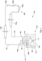
- a beverage dispense system 100 includes a beverage cooler 102 located remotely from a dispense location 104 at which one or more beverage dispense points 106a, 106b, 106c are provided (three of which are shown as an example only in Figure 1 ).
- the beverage cooler 102 comprises a coolant reservoir 108 having around its internal walls an evaporator 110 of a refrigeration system (not shown in Figure 1 ).
- the coolant reservoir 108 is arranged to hold a coolant which in the described embodiment may be water.
- the coolant may contain a freeze point suppressant such as glycol..
- the coolant may contain additives such as corrosion inhibitors. Any other coolant known in the art may be employed in the coolant circuit.
- the refrigeration system causes an ice bank to form on the evaporator 110 from the water content of the coolant of the coolant reservoir 108 as is known in the art.
- One or more product lines 112 containing beverage pass from a beverage storage source (not shown in Figure 1 ) through the beverage cooler 102 such that the beverage line 112 is submerged in the coolant. Heat from the beverage in the product line 112 is conducted to the ice bank via the coolant to cool the beverage.
- the coolant within the reservoir 108 is agitated using an agitator mechanism 114 that is driven by a motor 116.
- the agitator mechanism comprises a rotating impeller arranged to provide a flow of coolant within the reservoir 108.
- the agitator mechanism 114 may be any other mechanism suitable to cause movement of the coolant within the reservoir 108.
- the motor 116 may be variable in speed to drive the agitator mechanism 114 at different rates (e.g.
- the agitator 114 provides a flow of coolant over the ice bank in order to improve hear transfer from the beverage within the product line 112 to the ice bank.
- the product line 112 is contained within an insulated bundle of tubes commonly referred to as a python 118 in the art.
- the python 118 may contain any number of product lines 112 although in the described embodiment the python contains only one such product line 112 as shown in Figure 1 .
- a flow line 120 which conducts coolant from the reservoir 108 to the dispense location 104 and a return line 122 which conducts coolant from the dispense location 104 to the reservoir.
- the flow line 120 and return line 122 form a coolant circuit.
- Coolant is conducted around the coolant circuit by a pump 124.
- the pump 124 is driven by the motor 116, so that any change in speed of the pump 124 causes a corresponding change in speed of the agitator 114.
- a single drive shaft is provided to drive both the pump 124 and agitator 114, but in other embodiments a different drive mechanism can be provided such as separate drive shafts.
- separate motors may be provided to drive the agitator 114 and the pump 124 independently.
- the motor 116 may be varied in speed to provide variable pumping rates of coolant around the coolant circuit.
- the agitator may be omitted.
- the dispense points 106a, 106b, 106c each comprise a condensing dispense head or font (e.g. to form a thermally active dispense point or condensing font).
- Each dispense head is arranged to receive coolant from the python 118 such that all or part of its surface is reduced in temperature below the dew point allowing moisture in the ambient air to condense on the cooled surface.
- the condensation that forms on this condensing surface may in some embodiments freeze to form ice depending on the temperature of the coolant provided to the dispense point 106a, 106b, 106c.
- the number of condensing fonts may vary. In some embodiments, all the dispense points may comprise condensing fonts. In other embodiments the dispense points may include both condensing and non-condensing fonts. In other embodiments, all the dispense points may be non-condensing fonts.
- the beverage dispense system 100 further comprises a control unit 126 arranged to control the operation of the agitator 114 and the pump 124.
- the control unit 126 may be arranged to control the speed of the motor 116 in order to control the speed at which the pump 124 is driven and thereby control the rate of flow of coolant through the coolant circuit.
- the control unit may be additionally or alternatively arranged to control the pump 124 and agitator according to a predefined property of the dispense system as will be described later. By controlling the speed of the motor 116, the speed at which the agitator 114 is driven is also changed. By changing the rate at which the agitator 114 is driven, the rate at which coolant flows over the ice bank is changed.
- the control unit 126 may be directly mounted on the pump/motor assembly, or may in other embodiments be a separate unit in communication with the pump/motor assembly. Communication may be provided by any suitable means including but not limited to a wired link or a wireless link.
- the invention of this application provides an intelligent control unit 126 which is arranged to control the motor 116 (and thereby control the pump 124 and agitator 114) to improve the efficiency of the beverage dispense system and reduce energy consumption.
- control unit 126 is arranged to control the pump 124 and the agitator 114 such that the pressure of coolant is suitable for the number and/or type of dispense points 106a, 106b, 106c provided at the dispense location 104.
- the condensing fonts i.e. thermally active dispense points
- the minimum threshold pressure of coolant will depend on the number of condensing fonts supplied by the coolant circuit.
- the coolant supplied by the coolant circuit must be controlled accordingly.
- a greater number of condensing fonts will for example require a greater pressure of coolant to sustain the required condensation levels in comparison to a small number of dispensing fonts.
- the control unit 126 is arranged to control the rate of operation of the pump 124 and agitator 114 (via control of the speed of the motor 116) such that it is tailored to the number of condensing fonts.
- a multiple thermally active dispense points mode may therefore be provided in which the pump and agitator are controlled according to the number of thermally active dispense points (i.e. condensing fonts) connected to the system.
- the control unit is therefore arranged to control the rate of operation of the pump 124 and/or the agitator 114 at a minimum threshold that is determined according to the number of condensing fonts attached to the coolant circuit.
- the minimum threshold may be greater where the number of condensing fonts connected to the coolant circuit is greater.
- the dispense system 100 may further comprise a user input means 128 such as a selector switch or control panel which is arranged to receive an input specifying the number of condensing fonts supplied by the coolant circuit.
- the number of condensing fonts may be selected when the system is installed, or at a later time if the system is modified to include more or fewer condensing fonts.
- a multiple dispense point mode may be provided in which a minimum rate of operation of the pump and/or agitator is set to a predetermined level arranged to correspond to a particular number of dispense points (or condensing fonts). This may allow quick switching between use with a single dispense point (or condensing font), or with a particular number of dispense points (or condensing fonts).
- the multiple dispense point mode may be selected by the user input means 128.
- the control unit 126 may additionally or alternatively be arranged to provide an idle mode for the dispense system 100.
- the system may not be required to deliver product to the dispense location 104.
- restarting it when trading recommences can reduce the effectiveness of the system and may be energy inefficient.
- leaving the system running constantly is also energy inefficient and should be avoided. This is especially the case for condensing fonts which may require a large amount of energy to maintain condensation levels.
- control unit 126 is arranged to provide an idle mode in which a reduced temperature is maintained in the python 118 whilst condensation at the, or each, of the condensing fonts is kept to a minimum. This balances the need to keep the product remaining in the product line 112 cool to prevent degradation, whilst avoiding using large amounts of energy to unnecessarily produce condensation at the condensing font.
- cooling to the python and condensing fonts may be maintained so as to reduce the amount of energy required to reactivate the system once the idle mode is switched off. This reduces the overall energy consumption of the system.
- the control unit 126 may be arranged to receive a manual input by the user (via the same or a different input means used to select the number of dispensing fonts, for example) which specifies that the idle mode should be activated.
- a timer may be provided to provide a signal to the control unit 126 to activate the idle mode at a predetermined time (e.g. the time at which trading is expected to end).
- the idle mode may provide a full energy saving mode in which the operation of other modes of the controller (e.g. the multiple dispense points or freeze point suppressant mode) may be over-ridden if the operation of the pump 124 and/or agitator 114 exceeds a predetermined threshold. This may allow the lowest energy operation of the pump and/or agitator to be selected.
- the control unit 126 is further arranged to control the rate of operation of the pump 124 and the agitator 114 in response to temperature data associated with the coolant.
- the temperature data may be associated with the temperature of the coolant arriving at the reservoir 108 from the return line 122 and the temperature of the coolant within the reservoir 108.
- the dispense system 100 further comprises a data sensor 130 arranged to sense the temperature data.
- the data sensor 130 may be a single temperature sensor arranged to monitor the temperature of both the coolant return line 122 and coolant in the coolant reservoir 108.
- the data sensor 130 may comprises a first temperature sensor 130a arranged to monitor the temperature of the coolant from the return line 122 and a second temperature sensor 130b arranged to monitor the temperature of the coolant in the coolant reservoir 108.
- the rate of operation of the pump 124 and agitator 114 in response to temperature data associated with both the coolant at or near the point of return to the reservoir 108 (i.e. the return coolant) and the coolant within the reservoir 108 a more efficient response to changes in demand for product from the dispense system 100 can be provided. If, for example, the rate of operation of the pump 124 were to be only controlled in response to the return coolant temperature, a circumstance may exist where a sudden increase in demand for product to be delivered to the dispense location 104 leads to a delay in the appropriate response by the pump 124 and agitator 114 to maintain adequate cooling.
- the present invention alleviates this problem by controlling the rate of operation of the pump 124 and agitator 114 in response to temperature data associated with both the return coolant and the coolant within the reservoir 108. A change in either can therefore result in a change in the rate of operation of the pump 124 and the agitator 114. If a surge in demand for product were to occur, the control unit 126 is arranged to control the rate of operation of the pump 124 and agitator 114 in response to a change in temperature of the coolant within the reservoir 108, rather than waiting for the associated increase in coolant temperature at the coolant return line 112. This allows the control unit 126 to more quickly respond to an increase in the amount of product flowing through the product line 112.
- the pump 124 may tend to either operate at a maximum or minimum rate. This is because the controller may command a greater than necessary increase in the rate of operation of the pump 124 and agitator 114 in response to a sudden increase in the rate of flow of product through the product line 112.
- the controller of the present invention is arranged to employ a control algorithm in order to more closely match the rate of operation of the pump 124 to the demand for product.
- the control unit 126 is arranged to vary the rate of operation of the pump 124 and/or the agitator 114 in a range between a maximum rate and a minimum. The rate of operation may be adjusted according to the magnitude of the change in temperature of the coolant.
- the control algorithm may therefore provide a damping effect in which the response of the control unit 126 to a change in the temperature data is damped to avoid a greater than necessary increase in the rate of operation of the pump 124 and agitator 114. This reduces the energy consumption of the system.
- the controller may provide a freeze point suppressant mode in which the rate of operation of the pump 124 and/or the agitator 114 are modified to account for the presence of freeze point suppressant within the coolant.
- the freeze point suppressant mode may be selected by the user when a freeze point suppressant, such as Glycol for example, has been added to the coolant (or is used as the coolant).
- the temperature of the coolant may be less than 0°C.
- the temperature of coolant returning to the reservoir may be, for example, 3 or 4°C less than temperatures expected when a freeze point suppressant is not being used.
- the controller may therefore be arranged to control the rate of operation of the pump 124 and/or the agitator 114 at a first set of predetermined values corresponding to a normal mode in which the coolant does not comprise a freeze point suppressant, and a second set (which is different to the first) of predetermined values corresponding to a freeze point suppressant mode in which the coolant does comprise a freeze point suppressant.
- the freeze point suppressant mode may in some embodiments provide a sensor temperature offset in order to allow the operation of the pump 124 and/or agitator 124 to be controlled at the second set of predetermined values.
- the temperature offset may be applied to the temperature data measured by the data sensor 130.
- the temperature offset may be applied to the temperature data recorded by the first temperature sensor 130a arranged to monitor the temperature of the coolant from the return line 122. In other embodiments, the temperature offset may be applied to the data recorded by the second temperature sensor 130b. In some embodiments, the temperature offset may be a subtraction of 3 or 4°C. This is however only one example of the offset that may be applied, in other embodiments any other suitable temperature offset may be chosen according to the properties of the coolant.
- the freeze point suppressant mode may, in some embodiments, be selected via a user input means.
- the control unit 126, pump 124, agitator 114, motor 116 and data sensor 130 may be provided in an integrated coolant recirculation assembly 200, 300 as shown in Figures 2a , 2b and 3 .
- the integrated coolant recirculation assembly 200 comprises a single critically located temperature sensor 130 arranged to measure the coolant within the reservoir and the temperature of the coolant returning to the reservoir.
- two temperature sensors 130a, 130b are provided.
- a first temperature sensor 130a is arranged to measure the temperature of the coolant retuning to the reservoir and a second temperature sensor 130b within the reservoir.
- Figure 3 shows an alternative view of the integrated coolant recirculation assembly 300.
- the user input means 400 comprises a control panel having one or more user operable selectors such as buttons or switches forming a keypad to allow the user to select various modes of operation of the controller.
- the input means 400 may be located on the control unit 126.
- a first selector 402 is arranged to receive a user input to allow the freeze point suppressant mode described above to be selected.
- a second selector 404 is provided to select a thermally active dispense point mode (i.e. the condensing font mode) as described above.
- the second selector may be arranged to receive a user input of the number of thermally active dispense points being used, or may be arranged to select the thermally active dispense point mode corresponding to a pre-set number of thermally active dispense points.
- a third selector 406 may be arranged to allow selection of the idle mode previously described.
- additional selectors may be provided to set the timing or duration of the idle mode (e.g. may allow the setting of a timer or calendar function).
- any of the first, second or third of the selectors 402, 404, 406 may be omitted, or further selectors may be provided to receive any other user input that may be required.
- the integrated coolant recirculation assembly 200, 300 advantageously allows the present invention to be implemented in an existing beverage dispense system.
- the integrated assembly allows recirculation assembly to be retro-fitted to an existing system quickly, safely and with application certainty.
Landscapes
- Physics & Mathematics (AREA)
- Thermal Sciences (AREA)
- Engineering & Computer Science (AREA)
- Chemical & Material Sciences (AREA)
- Combustion & Propulsion (AREA)
- Mechanical Engineering (AREA)
- General Engineering & Computer Science (AREA)
- Devices For Dispensing Beverages (AREA)
Claims (12)
- Kühlmittelrezirkulationsvorrichtung (102) für ein Getränkeausgabesystem (100), wobei die Vorrichtung umfasst:einen Pumpmechanismus (124), der eingerichtet ist, um ein Kühlmittel über einen Kühlmittelkreislauf (120, 122) von einem Kühlmittelreservoir (108) zu einer Getränkeausgabestelle (104), die zumindest einen Ausgabepunkt (106a, 106b, 106c) aufweist, an dem Getränke ausgegeben werden, zu rezirkulieren, wobei der Pumpmechanismus durch einen Motor (116) angetrieben wird;einen Rührmechanismus (114), der eingerichtet ist, um ein Kühlmittel innerhalb des Kühlmittelreservoirs zu rühren, wobei der Rührmechanismus durch denselben oder einen verschiedenen Motor (116) angetrieben wird;einen Datensensor (130a, 130b), der eingerichtet ist, um die Temperatur des Kühlmittels in dem Kühlmittelreservoir (108) und/oder die Temperatur des Kühlmittels, das zu dem Kühlmittelreservoir (108) zurückkehrt, zu überwachen; undeine Steuereinheit (126), die mit dem Pumpmechanismus, dem Rührmechanismus und dem Datensensor in Verbindung steht;dadurch gekennzeichnet, dass:
die Steuereinheit eingerichtet ist, um die Geschwindigkeit des oder jedes Motors zu steuern, um die Betriebsrate des Rührmechanismus und des Pumpmechanismus bei einem minimalen Schwellenwert, der gemäß einer vordefinierten Anzahl von Kondensationsfonts, die an dem Kühlmittelkreislauf befestigt sind, bestimmt wird, wobei der minimale Schwellenwert größer ist, wenn die Anzahl der an dem Kühlmittelkreislauf befestigten Kondensationsfonts größer ist, und als Reaktion auf Änderungen in der Temperatur zu steuern. - Kühlmittelrezirkulationsvorrichtung nach Anspruch 1, wobei die Steuereinheit eingerichtet ist, um die Geschwindigkeit des oder jedes Motors zu steuern, um die Betriebsrate des Pumpmechanismus und/oder des Rührmechanismus basierend auf einer Temperaturänderung in entweder der Temperatur des Kühlmittels in dem in dem Kühlmittelreservoir oder der Temperatur des Kühlmittels, das zu dem Kühlmittelreservoir zurückkehrt, oder beiden zu steuern.
- Kühlmittelrezirkulationsvorrichtung nach Anspruch 1 oder Anspruch 2, wobei die Steuereinheit eingerichtet ist, um die Geschwindigkeit des oder jedes Motors zu steuern, um die Betriebsrate des Pumpmechanismus und/oder des Rührmechanismus gemäß einem Steueralgorithmus zu steuern, sodass die Betriebsrate an eine Änderung in einer Nachfrage für ein Getränk an der Ausgabestelle angepasst wird, und wobei der Steueralgorithmus konfiguriert ist, sodass die Steuereinheit eingerichtet ist, um die Betriebsrate des Pumpmechanismus und/oder des Rührmechanismus in einem Bereich zwischen einer maximalen Rate und einer minimalen Rate gemäß der Größe der Temperaturänderung des Kühlmittels zu variieren.
- Kühlmittelrezirkulationsvorrichtung nach einem der vorstehenden Ansprüche, wobei der Datensensor einen einzelnen Temperatursensor umfasst, der eingerichtet ist, um die Temperatur des Kühlmittels, das von dem Kühlmittelreservoir über den Kühlmittelkreislauf zurückkehrt, zu erfassen, und wobei optional der Temperatursensor eingerichtet ist, um sowohl die Temperatur des Kühlmittels, das von dem Kühlmittelreservoir über den Kühlmittelkreislauf zurückkehrt, als auch die Temperatur des Kühlmittels in dem Kühlmittelreservoir zu erfassen.
- Kühlmittelrezirkulationsvorrichtung nach einem der Ansprüche 1 bis 3, wobei der Datensensor einen ersten Temperatursensor umfasst, der eingerichtet ist, um die Temperatur des Kühlmittels, das von dem Kühlmittelreservoir über den Kühlmittelkreislauf zurückkehrt, zu erfassen, und einen zweiten Temperatursensor, der eingerichtet ist, um die Temperatur des Kühlmittels in dem Kühlmittelreservoir zu erfassen.
- Kühlmittelrezirkulationsvorrichtung nach Anspruch 1, weiter umfassend ein Benutzereingabemittel (128), das eingerichtet ist, um eine Eingabe, die die Anzahl von Kondensationsfonts, die an dem Kühlmittelkreislauf befestigt sind, spezifiziert, zu empfangen, und wobei optional das Eingabemittel einen Wahlschalter umfasst.
- Kühlmittelrezirkulationsvorrichtung nach einem der vorstehenden Ansprüche, wobei das Steuermittel eingerichtet ist, um den Betrieb der Pumpe zu steuern, sodass ein Schwellenwert-Kühlmitteldruck in dem Kühlmittelkreislauf bereitgestellt wird, und wobei optional der Schwellenwertdruck ausreichend ist, um Kühlung für eine Kondensationsfläche eines Kondensationsfonts bereitzustellen.
- Kühlmittelrezirkulationsvorrichtung nach einem der vorstehenden Ansprüche, wobei das Steuermittel auf eine Eingabe einer Anzahl von Kondensationsfonts, die an dem Kühlmittelkreislauf befestigt sind, reagiert, um den Betrieb der Pumpe einzustellen, um Kühlung für alle Kondensationsfonts, die an dem Kühlmittelkreislauf befestigt sind, bereitzustellen, und wobei optional eine Pumpgeschwindigkeit als Reaktion auf eine Benutzerauswahl der Anzahl von Kondensationsfonts einstellbar ist, um Kühlung für alle Kondensationsfonts, die an dem Kühlmittelkreislauf befestigt sind, bereitzustellen.
- Kühlmittelrezirkulationsvorrichtung nach einem der vorstehenden Ansprüche, wobei die Steuereinheit eingerichtet ist, um einen Leerlaufmodus bereitzustellen, wobei in dem Leerlaufmodus das Kühlmittel in dem Kühlmittelkreislauf vorzugsweise ausreichend ist, um die Getränkekühlung aufrechtzuerhalten, und wobei in dem Leerlaufmodus der Pumpmechanismus, der Rührmechanismus oder beide vorzugsweise bei einer vorbestimmten minimalen Rate betrieben werden.
- Kühlmittelrezirkulationsvorrichtung nach Anspruch 9, weiter umfassend ein Benutzereingabemittel (128), das mit der Steuereinheit in Verbindung steht, wobei das Benutzereingabemittel eingerichtet ist, um eine Eingabe zu empfangen, die den Leerlaufmodus auswählt, und vorzugsweise weiter umfassend ein Zeitgebermittel, das mit der Steuereinheit in Verbindung steht, wobei das Zeitgebermittel eingerichtet ist, um den Leerlaufmodus zu einer vorbestimmten Zeit zu aktivieren.
- Kühlmittelrezirkulationsvorrichtung nach einem der vorstehenden Ansprüche, wobei die Steuereinheit eingerichtet ist, um einen Gefrierpunktunterdrückungsbetriebsmodus, in dem das Kühlmittel ein Gefrierpunktunterdrückungsmittel umfasst, um die Kühlmitteltemperatur in dem Kühlmittelreservoir (108) und/oder die Temperatur des Kühlmittels, das zu dem Kühlmittelreservoir (108) zurückkehrt, zu verringern, und einen normalen Betriebsmodus, in dem das Kühlmittel kein Gefrierpunktunterdrückungsmittel umfasst, bereitzustellen; und wobei die Steuereinheit eingerichtet ist, um die Betriebsrate des Rührmechanismus und des Pumpmechanismus zu steuern bei: einem ersten Satz von vorbestimmten Werten einer Betriebsrate des Rührmechanismus und des Pumpmechanismus, die dem normalen Modus entsprechen; und einem zweiten Satz von vorbestimmten Werten einer Betriebsrate des Rührmechanismus und des Pumpmechanismus, die dem Gefrierpunktunterdrückungsmodus entsprechen, wobei der erste und der zweite Satz von vorbestimmten Werten verschieden sind, wobei der Gefrierpunktunterdrückungsmodus eingerichtet ist, um einen Versatz auf die Temperaturdaten anzuwenden, die durch den Datensensor bereitgestellt werden, um zu ermöglichen, dass der Betrieb des Rührmechanismus und des Pumpmechanismus bei dem zweiten Satz von vorbestimmten Werten gesteuert werden kann.
- Kühlmittelrezirkulationsvorrichtung nach Anspruch 11, weiter umfassend ein Benutzereingabemittel (128), das eingerichtet ist, um eine Eingabe zu empfangen, die den Gefrierpunktunterdrückungsmodus auswählt.
Priority Applications (2)
| Application Number | Priority Date | Filing Date | Title |
|---|---|---|---|
| EP19166269.1A EP3524570B1 (de) | 2015-05-05 | 2016-05-04 | Kühlmittelrezirkulationsvorrichtung für ein getränkeausgabesystem |
| EP19166265.9A EP3521239B1 (de) | 2015-05-05 | 2016-05-04 | Kühlmittelrezirkulationsvorrichtung für ein getränkeausgabesystem |
Applications Claiming Priority (2)
| Application Number | Priority Date | Filing Date | Title |
|---|---|---|---|
| GBGB1507651.6A GB201507651D0 (en) | 2015-05-05 | 2015-05-05 | A coolant recirculation apparatus for a beverage dispense system |
| GB1515906.4A GB2538114B (en) | 2015-05-05 | 2015-09-08 | A coolant recirculation apparatus for a beverage dispense system |
Related Child Applications (4)
| Application Number | Title | Priority Date | Filing Date |
|---|---|---|---|
| EP19166265.9A Division EP3521239B1 (de) | 2015-05-05 | 2016-05-04 | Kühlmittelrezirkulationsvorrichtung für ein getränkeausgabesystem |
| EP19166265.9A Division-Into EP3521239B1 (de) | 2015-05-05 | 2016-05-04 | Kühlmittelrezirkulationsvorrichtung für ein getränkeausgabesystem |
| EP19166269.1A Division EP3524570B1 (de) | 2015-05-05 | 2016-05-04 | Kühlmittelrezirkulationsvorrichtung für ein getränkeausgabesystem |
| EP19166269.1A Division-Into EP3524570B1 (de) | 2015-05-05 | 2016-05-04 | Kühlmittelrezirkulationsvorrichtung für ein getränkeausgabesystem |
Publications (2)
| Publication Number | Publication Date |
|---|---|
| EP3090980A1 EP3090980A1 (de) | 2016-11-09 |
| EP3090980B1 true EP3090980B1 (de) | 2019-06-19 |
Family
ID=53489135
Family Applications (3)
| Application Number | Title | Priority Date | Filing Date |
|---|---|---|---|
| EP19166269.1A Not-in-force EP3524570B1 (de) | 2015-05-05 | 2016-05-04 | Kühlmittelrezirkulationsvorrichtung für ein getränkeausgabesystem |
| EP19166265.9A Not-in-force EP3521239B1 (de) | 2015-05-05 | 2016-05-04 | Kühlmittelrezirkulationsvorrichtung für ein getränkeausgabesystem |
| EP16168452.7A Active EP3090980B1 (de) | 2015-05-05 | 2016-05-04 | Kühlmittelrezirkulationsvorrichtung für ein getränkeausgabesystem |
Family Applications Before (2)
| Application Number | Title | Priority Date | Filing Date |
|---|---|---|---|
| EP19166269.1A Not-in-force EP3524570B1 (de) | 2015-05-05 | 2016-05-04 | Kühlmittelrezirkulationsvorrichtung für ein getränkeausgabesystem |
| EP19166265.9A Not-in-force EP3521239B1 (de) | 2015-05-05 | 2016-05-04 | Kühlmittelrezirkulationsvorrichtung für ein getränkeausgabesystem |
Country Status (3)
| Country | Link |
|---|---|
| US (1) | US10793413B2 (de) |
| EP (3) | EP3524570B1 (de) |
| GB (2) | GB201507651D0 (de) |
Families Citing this family (9)
| Publication number | Priority date | Publication date | Assignee | Title |
|---|---|---|---|---|
| GB201507651D0 (en) | 2015-05-05 | 2015-06-17 | Cornelius Beverage Technolgies Ltd | A coolant recirculation apparatus for a beverage dispense system |
| US11034569B2 (en) | 2018-02-14 | 2021-06-15 | Taphandles Llc | Cooled beverage dispensing systems and associated devices |
| JP2019167137A (ja) * | 2018-03-23 | 2019-10-03 | アサヒビール株式会社 | 液体品質管理装置及び方法 |
| US11255583B2 (en) * | 2019-02-05 | 2022-02-22 | The Boeing Company | Dry ice-based cooling systems |
| US11479455B2 (en) * | 2019-05-17 | 2022-10-25 | Pepsico, Inc. | Water dispensing station |
| JP7591980B2 (ja) * | 2021-06-11 | 2024-11-29 | サントリーホールディングス株式会社 | 配管温度調節システム及び配管温度調節方法 |
| GB2609953B (en) * | 2021-08-18 | 2026-04-01 | Technik2 Ltd | Improvements in or relating to energy saving |
| MX2024008973A (es) * | 2022-01-28 | 2024-08-20 | Bartrack Inc | Monitoreo del equilibrio y dispensacion de un sistema de dispensacion de fluidos para mejorar la calidad y la eficiencia. |
| WO2023148589A1 (en) * | 2022-02-01 | 2023-08-10 | Bevco S.R.L. | Environmentally-friendly system for the dispensing of refrigerated beverages |
Family Cites Families (14)
| Publication number | Priority date | Publication date | Assignee | Title |
|---|---|---|---|---|
| IES960664A2 (en) | 1996-09-20 | 1996-12-11 | Daniel Joseph Ryan | An ice bank cooler system |
| US6644508B2 (en) | 2001-09-20 | 2003-11-11 | Lancer Partnership, Ltd. | Beverage dispenser |
| US6709391B2 (en) * | 2002-05-23 | 2004-03-23 | Koninklijke Philips Electronics N.V. | Diagnostic ultrasound system cart with laterally articulating control panel |
| US8511105B2 (en) * | 2002-11-13 | 2013-08-20 | Deka Products Limited Partnership | Water vending apparatus |
| US7757498B2 (en) | 2004-04-03 | 2010-07-20 | Wolski Peter F | Cold carbonation and cold syrup system for beverage dispenser with remote tower |
| GB2419176B (en) | 2004-10-18 | 2009-04-08 | Mf Refrigeration Ltd | A Device for Cooling Liquids |
| GB2448621B (en) | 2006-07-08 | 2010-04-28 | Imi Cornelius | Beverage dispense |
| AU2008346270B2 (en) | 2008-01-08 | 2013-01-10 | Marmon Foodservice Technologies UK Limited | Post-mix beverage dispenser with cooler |
| US8359877B2 (en) * | 2008-08-15 | 2013-01-29 | Deka Products Limited Partnership | Water vending apparatus |
| GB2465632A (en) * | 2008-11-28 | 2010-06-02 | Imi Cornelius | Icebank cooler |
| GB2488827B (en) | 2011-03-10 | 2014-07-02 | Mf Refrigeration Ltd | Refrigeration system |
| GB2502631B (en) | 2012-06-01 | 2018-07-18 | Cornelius Beverage Tech Limited | Beverage dispense |
| JP6011184B2 (ja) * | 2012-09-14 | 2016-10-19 | 富士電機株式会社 | 飲料供給装置 |
| GB201507651D0 (en) | 2015-05-05 | 2015-06-17 | Cornelius Beverage Technolgies Ltd | A coolant recirculation apparatus for a beverage dispense system |
-
2015
- 2015-05-05 GB GBGB1507651.6A patent/GB201507651D0/en not_active Ceased
- 2015-09-08 GB GB1515906.4A patent/GB2538114B/en not_active Expired - Fee Related
-
2016
- 2016-01-21 US US15/003,228 patent/US10793413B2/en active Active
- 2016-05-04 EP EP19166269.1A patent/EP3524570B1/de not_active Not-in-force
- 2016-05-04 EP EP19166265.9A patent/EP3521239B1/de not_active Not-in-force
- 2016-05-04 EP EP16168452.7A patent/EP3090980B1/de active Active
Non-Patent Citations (1)
| Title |
|---|
| None * |
Also Published As
| Publication number | Publication date |
|---|---|
| US20160325979A1 (en) | 2016-11-10 |
| GB201507651D0 (en) | 2015-06-17 |
| EP3524570B1 (de) | 2021-02-17 |
| GB201515906D0 (en) | 2015-10-21 |
| EP3521239B1 (de) | 2021-03-24 |
| GB2538114B (en) | 2018-01-03 |
| EP3524570A1 (de) | 2019-08-14 |
| GB2538114A (en) | 2016-11-09 |
| EP3521239A1 (de) | 2019-08-07 |
| US10793413B2 (en) | 2020-10-06 |
| EP3090980A1 (de) | 2016-11-09 |
Similar Documents
| Publication | Publication Date | Title |
|---|---|---|
| EP3090980B1 (de) | Kühlmittelrezirkulationsvorrichtung für ein getränkeausgabesystem | |
| AU2008346270B2 (en) | Post-mix beverage dispenser with cooler | |
| US5279446A (en) | Beverage cooling system | |
| EP1876137B1 (de) | Getränkeausgabe | |
| EP1683756A2 (de) | Bierschankvorrichtung mit Temperaturwähler | |
| US20080006050A1 (en) | Multiple barrel frozen product dispenser | |
| US3370755A (en) | Carbonated water system | |
| KR20190109103A (ko) | 음료 냉각 장치 | |
| US20160187044A1 (en) | Variable Differential and Offset Control for Refrigeration Systems | |
| GB2471159A (en) | Single tank beverage and ice tower cooler | |
| EP0191436A1 (de) | Vorrichtung zum Kühlen und Ausschenken von Getränken | |
| GB2502631A (en) | Beverage dispense system which creates condensation or ice on a dispense head | |
| GB2558112B (en) | Method of controlling condensation on a beverage dispense head | |
| US20110296852A1 (en) | Energy Management System | |
| EP2515060A2 (de) | Kühler | |
| GB2450925A (en) | An Ice Bank Cooler with a Coolant Freezing Below the Freezing Point of Water | |
| GB2446792A (en) | Beverage dispense system | |
| EP1510499A1 (de) | Gekühltes Getränkeausgabesystem | |
| GB2441215A (en) | Beverage dispense | |
| JPH04294788A (ja) | 冷却飲料ディスペンサー用乾式冷却システム | |
| GB2383322A (en) | Beverage dispense system | |
| IE86196B1 (en) | Beverage coolers | |
| CA2594193A1 (en) | Beverage dispensing system with temperature control |
Legal Events
| Date | Code | Title | Description |
|---|---|---|---|
| PUAI | Public reference made under article 153(3) epc to a published international application that has entered the european phase |
Free format text: ORIGINAL CODE: 0009012 |
|
| AK | Designated contracting states |
Kind code of ref document: A1 Designated state(s): AL AT BE BG CH CY CZ DE DK EE ES FI FR GB GR HR HU IE IS IT LI LT LU LV MC MK MT NL NO PL PT RO RS SE SI SK SM TR |
|
| AX | Request for extension of the european patent |
Extension state: BA ME |
|
| STAA | Information on the status of an ep patent application or granted ep patent |
Free format text: STATUS: REQUEST FOR EXAMINATION WAS MADE |
|
| TPAC | Observations filed by third parties |
Free format text: ORIGINAL CODE: EPIDOSNTIPA |
|
| 17P | Request for examination filed |
Effective date: 20170403 |
|
| RBV | Designated contracting states (corrected) |
Designated state(s): AL AT BE BG CH CY CZ DE DK EE ES FI FR GB GR HR HU IE IS IT LI LT LU LV MC MK MT NL NO PL PT RO RS SE SI SK SM TR |
|
| STAA | Information on the status of an ep patent application or granted ep patent |
Free format text: STATUS: EXAMINATION IS IN PROGRESS |
|
| 17Q | First examination report despatched |
Effective date: 20170704 |
|
| GRAP | Despatch of communication of intention to grant a patent |
Free format text: ORIGINAL CODE: EPIDOSNIGR1 |
|
| STAA | Information on the status of an ep patent application or granted ep patent |
Free format text: STATUS: GRANT OF PATENT IS INTENDED |
|
| INTG | Intention to grant announced |
Effective date: 20190104 |
|
| GRAS | Grant fee paid |
Free format text: ORIGINAL CODE: EPIDOSNIGR3 |
|
| GRAJ | Information related to disapproval of communication of intention to grant by the applicant or resumption of examination proceedings by the epo deleted |
Free format text: ORIGINAL CODE: EPIDOSDIGR1 |
|
| GRAL | Information related to payment of fee for publishing/printing deleted |
Free format text: ORIGINAL CODE: EPIDOSDIGR3 |
|
| STAA | Information on the status of an ep patent application or granted ep patent |
Free format text: STATUS: EXAMINATION IS IN PROGRESS |
|
| GRAP | Despatch of communication of intention to grant a patent |
Free format text: ORIGINAL CODE: EPIDOSNIGR1 |
|
| STAA | Information on the status of an ep patent application or granted ep patent |
Free format text: STATUS: GRANT OF PATENT IS INTENDED |
|
| INTC | Intention to grant announced (deleted) | ||
| INTG | Intention to grant announced |
Effective date: 20190417 |
|
| GRAA | (expected) grant |
Free format text: ORIGINAL CODE: 0009210 |
|
| STAA | Information on the status of an ep patent application or granted ep patent |
Free format text: STATUS: THE PATENT HAS BEEN GRANTED |
|
| AK | Designated contracting states |
Kind code of ref document: B1 Designated state(s): AL AT BE BG CH CY CZ DE DK EE ES FI FR GB GR HR HU IE IS IT LI LT LU LV MC MK MT NL NO PL PT RO RS SE SI SK SM TR |
|
| REG | Reference to a national code |
Ref country code: GB Ref legal event code: FG4D |
|
| REG | Reference to a national code |
Ref country code: CH Ref legal event code: EP |
|
| REG | Reference to a national code |
Ref country code: IE Ref legal event code: FG4D |
|
| REG | Reference to a national code |
Ref country code: AT Ref legal event code: REF Ref document number: 1145253 Country of ref document: AT Kind code of ref document: T Effective date: 20190715 |
|
| REG | Reference to a national code |
Ref country code: DE Ref legal event code: R096 Ref document number: 602016015406 Country of ref document: DE |
|
| REG | Reference to a national code |
Ref country code: NL Ref legal event code: MP Effective date: 20190619 |
|
| PG25 | Lapsed in a contracting state [announced via postgrant information from national office to epo] |
Ref country code: AL Free format text: LAPSE BECAUSE OF FAILURE TO SUBMIT A TRANSLATION OF THE DESCRIPTION OR TO PAY THE FEE WITHIN THE PRESCRIBED TIME-LIMIT Effective date: 20190619 Ref country code: SE Free format text: LAPSE BECAUSE OF FAILURE TO SUBMIT A TRANSLATION OF THE DESCRIPTION OR TO PAY THE FEE WITHIN THE PRESCRIBED TIME-LIMIT Effective date: 20190619 Ref country code: HR Free format text: LAPSE BECAUSE OF FAILURE TO SUBMIT A TRANSLATION OF THE DESCRIPTION OR TO PAY THE FEE WITHIN THE PRESCRIBED TIME-LIMIT Effective date: 20190619 Ref country code: NO Free format text: LAPSE BECAUSE OF FAILURE TO SUBMIT A TRANSLATION OF THE DESCRIPTION OR TO PAY THE FEE WITHIN THE PRESCRIBED TIME-LIMIT Effective date: 20190919 Ref country code: LT Free format text: LAPSE BECAUSE OF FAILURE TO SUBMIT A TRANSLATION OF THE DESCRIPTION OR TO PAY THE FEE WITHIN THE PRESCRIBED TIME-LIMIT Effective date: 20190619 Ref country code: FI Free format text: LAPSE BECAUSE OF FAILURE TO SUBMIT A TRANSLATION OF THE DESCRIPTION OR TO PAY THE FEE WITHIN THE PRESCRIBED TIME-LIMIT Effective date: 20190619 |
|
| REG | Reference to a national code |
Ref country code: LT Ref legal event code: MG4D |
|
| PG25 | Lapsed in a contracting state [announced via postgrant information from national office to epo] |
Ref country code: RS Free format text: LAPSE BECAUSE OF FAILURE TO SUBMIT A TRANSLATION OF THE DESCRIPTION OR TO PAY THE FEE WITHIN THE PRESCRIBED TIME-LIMIT Effective date: 20190619 Ref country code: LV Free format text: LAPSE BECAUSE OF FAILURE TO SUBMIT A TRANSLATION OF THE DESCRIPTION OR TO PAY THE FEE WITHIN THE PRESCRIBED TIME-LIMIT Effective date: 20190619 Ref country code: BG Free format text: LAPSE BECAUSE OF FAILURE TO SUBMIT A TRANSLATION OF THE DESCRIPTION OR TO PAY THE FEE WITHIN THE PRESCRIBED TIME-LIMIT Effective date: 20190919 Ref country code: GR Free format text: LAPSE BECAUSE OF FAILURE TO SUBMIT A TRANSLATION OF THE DESCRIPTION OR TO PAY THE FEE WITHIN THE PRESCRIBED TIME-LIMIT Effective date: 20190920 |
|
| REG | Reference to a national code |
Ref country code: AT Ref legal event code: MK05 Ref document number: 1145253 Country of ref document: AT Kind code of ref document: T Effective date: 20190619 |
|
| PG25 | Lapsed in a contracting state [announced via postgrant information from national office to epo] |
Ref country code: AT Free format text: LAPSE BECAUSE OF FAILURE TO SUBMIT A TRANSLATION OF THE DESCRIPTION OR TO PAY THE FEE WITHIN THE PRESCRIBED TIME-LIMIT Effective date: 20190619 Ref country code: SK Free format text: LAPSE BECAUSE OF FAILURE TO SUBMIT A TRANSLATION OF THE DESCRIPTION OR TO PAY THE FEE WITHIN THE PRESCRIBED TIME-LIMIT Effective date: 20190619 Ref country code: PT Free format text: LAPSE BECAUSE OF FAILURE TO SUBMIT A TRANSLATION OF THE DESCRIPTION OR TO PAY THE FEE WITHIN THE PRESCRIBED TIME-LIMIT Effective date: 20191021 Ref country code: EE Free format text: LAPSE BECAUSE OF FAILURE TO SUBMIT A TRANSLATION OF THE DESCRIPTION OR TO PAY THE FEE WITHIN THE PRESCRIBED TIME-LIMIT Effective date: 20190619 Ref country code: NL Free format text: LAPSE BECAUSE OF FAILURE TO SUBMIT A TRANSLATION OF THE DESCRIPTION OR TO PAY THE FEE WITHIN THE PRESCRIBED TIME-LIMIT Effective date: 20190619 Ref country code: CZ Free format text: LAPSE BECAUSE OF FAILURE TO SUBMIT A TRANSLATION OF THE DESCRIPTION OR TO PAY THE FEE WITHIN THE PRESCRIBED TIME-LIMIT Effective date: 20190619 Ref country code: RO Free format text: LAPSE BECAUSE OF FAILURE TO SUBMIT A TRANSLATION OF THE DESCRIPTION OR TO PAY THE FEE WITHIN THE PRESCRIBED TIME-LIMIT Effective date: 20190619 |
|
| PG25 | Lapsed in a contracting state [announced via postgrant information from national office to epo] |
Ref country code: ES Free format text: LAPSE BECAUSE OF FAILURE TO SUBMIT A TRANSLATION OF THE DESCRIPTION OR TO PAY THE FEE WITHIN THE PRESCRIBED TIME-LIMIT Effective date: 20190619 Ref country code: IS Free format text: LAPSE BECAUSE OF FAILURE TO SUBMIT A TRANSLATION OF THE DESCRIPTION OR TO PAY THE FEE WITHIN THE PRESCRIBED TIME-LIMIT Effective date: 20191019 Ref country code: SM Free format text: LAPSE BECAUSE OF FAILURE TO SUBMIT A TRANSLATION OF THE DESCRIPTION OR TO PAY THE FEE WITHIN THE PRESCRIBED TIME-LIMIT Effective date: 20190619 Ref country code: IT Free format text: LAPSE BECAUSE OF FAILURE TO SUBMIT A TRANSLATION OF THE DESCRIPTION OR TO PAY THE FEE WITHIN THE PRESCRIBED TIME-LIMIT Effective date: 20190619 |
|
| PG25 | Lapsed in a contracting state [announced via postgrant information from national office to epo] |
Ref country code: TR Free format text: LAPSE BECAUSE OF FAILURE TO SUBMIT A TRANSLATION OF THE DESCRIPTION OR TO PAY THE FEE WITHIN THE PRESCRIBED TIME-LIMIT Effective date: 20190619 |
|
| PG25 | Lapsed in a contracting state [announced via postgrant information from national office to epo] |
Ref country code: PL Free format text: LAPSE BECAUSE OF FAILURE TO SUBMIT A TRANSLATION OF THE DESCRIPTION OR TO PAY THE FEE WITHIN THE PRESCRIBED TIME-LIMIT Effective date: 20190619 Ref country code: DK Free format text: LAPSE BECAUSE OF FAILURE TO SUBMIT A TRANSLATION OF THE DESCRIPTION OR TO PAY THE FEE WITHIN THE PRESCRIBED TIME-LIMIT Effective date: 20190619 |
|
| PG25 | Lapsed in a contracting state [announced via postgrant information from national office to epo] |
Ref country code: IS Free format text: LAPSE BECAUSE OF FAILURE TO SUBMIT A TRANSLATION OF THE DESCRIPTION OR TO PAY THE FEE WITHIN THE PRESCRIBED TIME-LIMIT Effective date: 20200224 |
|
| REG | Reference to a national code |
Ref country code: DE Ref legal event code: R097 Ref document number: 602016015406 Country of ref document: DE |
|
| PLBE | No opposition filed within time limit |
Free format text: ORIGINAL CODE: 0009261 |
|
| STAA | Information on the status of an ep patent application or granted ep patent |
Free format text: STATUS: NO OPPOSITION FILED WITHIN TIME LIMIT |
|
| PG2D | Information on lapse in contracting state deleted |
Ref country code: IS |
|
| PGFP | Annual fee paid to national office [announced via postgrant information from national office to epo] |
Ref country code: FR Payment date: 20200421 Year of fee payment: 5 |
|
| 26N | No opposition filed |
Effective date: 20200603 |
|
| PG25 | Lapsed in a contracting state [announced via postgrant information from national office to epo] |
Ref country code: SI Free format text: LAPSE BECAUSE OF FAILURE TO SUBMIT A TRANSLATION OF THE DESCRIPTION OR TO PAY THE FEE WITHIN THE PRESCRIBED TIME-LIMIT Effective date: 20190619 |
|
| PG25 | Lapsed in a contracting state [announced via postgrant information from national office to epo] |
Ref country code: CH Free format text: LAPSE BECAUSE OF NON-PAYMENT OF DUE FEES Effective date: 20200531 Ref country code: MC Free format text: LAPSE BECAUSE OF FAILURE TO SUBMIT A TRANSLATION OF THE DESCRIPTION OR TO PAY THE FEE WITHIN THE PRESCRIBED TIME-LIMIT Effective date: 20190619 Ref country code: LI Free format text: LAPSE BECAUSE OF NON-PAYMENT OF DUE FEES Effective date: 20200531 |
|
| REG | Reference to a national code |
Ref country code: BE Ref legal event code: MM Effective date: 20200531 |
|
| PG25 | Lapsed in a contracting state [announced via postgrant information from national office to epo] |
Ref country code: LU Free format text: LAPSE BECAUSE OF NON-PAYMENT OF DUE FEES Effective date: 20200504 |
|
| PG25 | Lapsed in a contracting state [announced via postgrant information from national office to epo] |
Ref country code: BE Free format text: LAPSE BECAUSE OF NON-PAYMENT OF DUE FEES Effective date: 20200531 |
|
| REG | Reference to a national code |
Ref country code: DE Ref legal event code: R082 Ref document number: 602016015406 Country of ref document: DE Representative=s name: DEHMEL & BETTENHAUSEN PATENTANWAELTE PARTMBB, DE Ref country code: DE Ref legal event code: R081 Ref document number: 602016015406 Country of ref document: DE Owner name: CELLI GROUP (UK) LIMITED, GB Free format text: FORMER OWNER: CORNELIUS BEVERAGE TECHNOLOGIES LTD., BRIGHOUSE, WEST YORKSHIRE, GB |
|
| PGFP | Annual fee paid to national office [announced via postgrant information from national office to epo] |
Ref country code: IE Payment date: 20210525 Year of fee payment: 6 |
|
| REG | Reference to a national code |
Ref country code: GB Ref legal event code: 732E Free format text: REGISTERED BETWEEN 20210805 AND 20210811 |
|
| PG25 | Lapsed in a contracting state [announced via postgrant information from national office to epo] |
Ref country code: MT Free format text: LAPSE BECAUSE OF FAILURE TO SUBMIT A TRANSLATION OF THE DESCRIPTION OR TO PAY THE FEE WITHIN THE PRESCRIBED TIME-LIMIT Effective date: 20190619 Ref country code: FR Free format text: LAPSE BECAUSE OF NON-PAYMENT OF DUE FEES Effective date: 20210531 Ref country code: CY Free format text: LAPSE BECAUSE OF FAILURE TO SUBMIT A TRANSLATION OF THE DESCRIPTION OR TO PAY THE FEE WITHIN THE PRESCRIBED TIME-LIMIT Effective date: 20190619 |
|
| PG25 | Lapsed in a contracting state [announced via postgrant information from national office to epo] |
Ref country code: MK Free format text: LAPSE BECAUSE OF FAILURE TO SUBMIT A TRANSLATION OF THE DESCRIPTION OR TO PAY THE FEE WITHIN THE PRESCRIBED TIME-LIMIT Effective date: 20190619 |
|
| PG25 | Lapsed in a contracting state [announced via postgrant information from national office to epo] |
Ref country code: IE Free format text: LAPSE BECAUSE OF NON-PAYMENT OF DUE FEES Effective date: 20220504 |
|
| PGFP | Annual fee paid to national office [announced via postgrant information from national office to epo] |
Ref country code: DE Payment date: 20240313 Year of fee payment: 9 |
|
| PGFP | Annual fee paid to national office [announced via postgrant information from national office to epo] |
Ref country code: GB Payment date: 20250630 Year of fee payment: 10 |
|
| REG | Reference to a national code |
Ref country code: DE Ref legal event code: R119 Ref document number: 602016015406 Country of ref document: DE |
|
| PG25 | Lapsed in a contracting state [announced via postgrant information from national office to epo] |
Ref country code: DE Free format text: LAPSE BECAUSE OF NON-PAYMENT OF DUE FEES Effective date: 20251202 |