EP3090928A1 - Cabin for a vehicle, in particular for an agricultural tractor - Google Patents
Cabin for a vehicle, in particular for an agricultural tractor Download PDFInfo
- Publication number
- EP3090928A1 EP3090928A1 EP16166498.2A EP16166498A EP3090928A1 EP 3090928 A1 EP3090928 A1 EP 3090928A1 EP 16166498 A EP16166498 A EP 16166498A EP 3090928 A1 EP3090928 A1 EP 3090928A1
- Authority
- EP
- European Patent Office
- Prior art keywords
- cabin
- panel
- screw element
- frame
- support structure
- Prior art date
- Legal status (The legal status is an assumption and is not a legal conclusion. Google has not performed a legal analysis and makes no representation as to the accuracy of the status listed.)
- Granted
Links
Images


Classifications
-
- B—PERFORMING OPERATIONS; TRANSPORTING
- B62—LAND VEHICLES FOR TRAVELLING OTHERWISE THAN ON RAILS
- B62D—MOTOR VEHICLES; TRAILERS
- B62D33/00—Superstructures for load-carrying vehicles
- B62D33/06—Drivers' cabs
-
- B—PERFORMING OPERATIONS; TRANSPORTING
- B60—VEHICLES IN GENERAL
- B60J—WINDOWS, WINDSCREENS, NON-FIXED ROOFS, DOORS, OR SIMILAR DEVICES FOR VEHICLES; REMOVABLE EXTERNAL PROTECTIVE COVERINGS SPECIALLY ADAPTED FOR VEHICLES
- B60J5/00—Doors
- B60J5/04—Doors arranged at the vehicle sides
- B60J5/0486—Special type
- B60J5/0487—Special type simplified doors related to cabins of, e.g. golf carts, tractors, jeeps, cranes, forklifts, etc.
-
- E—FIXED CONSTRUCTIONS
- E02—HYDRAULIC ENGINEERING; FOUNDATIONS; SOIL SHIFTING
- E02F—DREDGING; SOIL-SHIFTING
- E02F9/00—Component parts of dredgers or soil-shifting machines, not restricted to one of the kinds covered by groups E02F3/00 - E02F7/00
- E02F9/08—Superstructures; Supports for superstructures
- E02F9/0833—Improving access, e.g. for maintenance, steps for improving driver's access, handrails
-
- E—FIXED CONSTRUCTIONS
- E02—HYDRAULIC ENGINEERING; FOUNDATIONS; SOIL SHIFTING
- E02F—DREDGING; SOIL-SHIFTING
- E02F9/00—Component parts of dredgers or soil-shifting machines, not restricted to one of the kinds covered by groups E02F3/00 - E02F7/00
- E02F9/08—Superstructures; Supports for superstructures
- E02F9/0858—Arrangement of component parts installed on superstructures not otherwise provided for, e.g. electric components, fenders, air-conditioning units
- E02F9/0891—Lids or bonnets or doors or details thereof
-
- E—FIXED CONSTRUCTIONS
- E02—HYDRAULIC ENGINEERING; FOUNDATIONS; SOIL SHIFTING
- E02F—DREDGING; SOIL-SHIFTING
- E02F9/00—Component parts of dredgers or soil-shifting machines, not restricted to one of the kinds covered by groups E02F3/00 - E02F7/00
- E02F9/16—Cabins, platforms, or the like, for drivers
Definitions
- the present invention refers to a cabin for a vehicle, in particular for an agricultural tractor, as well as to an adjustment device of a panel of such a cabin, like for example the window of a door.
- the main function of the cabin of a vehicle is to protect the driver and the possible passengers.
- the cabin must also make the vehicle as comfortable as possible to use, whether it is an automobile rather than operating or farming machinery.
- the cabin of a farming machine like for example a tractor, must not only make the work of the operator comfortable, but must also ensure the maximum visibility in any operative condition.
- the current cabins for agricultural tractors are characterised by large paned surfaces, by a windscreen and/or by a sometimes openable rear window, so as to improve the aeration of the cabin itself, as well as by doors made almost entirely with transparent panels, so as to increase lateral visibility for the driver. These cabins can also be provided with access point and emergency exits. All of the panels, whether paned, opaque, openable or fixed, of the cabin of an agricultural tractor are usually mounted on a frame fixed on the bearing structure of the vehicle.
- the frame of the cabin and the relative openable panels generally consist of rigid systems, which sealingly couple through gaskets.
- the gaskets are capable of compressing and adapting to small variations in position of the panels with respect to the frame when such panels are in their closed configuration.
- the components of a cabin for vehicles can undergo dimensional and position variations due to productions and technological problems.
- the tolerances between the various components of a cabin can vary by an amount that generally increases at the wear of the vehicle increases.
- the climatic conditions in which the vehicle operates can also influence, within certain limits, the tolerances between the various components of a cabin.
- the thermal expansions caused by particularly high temperatures can vary, even if reversibly, the position of the panels with respect to the frame, in particular as far as the doors are concerned.
- the gaskets are not always able to compensate for the aforementioned variations in position, especially when such variations exceed a certain tolerance.
- the relative gasket may not be correctly compressed, or even in some sections not adhere at all to the perimeter edge of the door opening.
- the aim of the present invention is therefore to make a cabin for a vehicle, in particular for an agricultural tractor, which is able to solve the aforementioned drawbacks of the prior art in an extremely simple, cost-effective and particularly functional manner.
- an aim of the present invention is to make a cabin for a vehicle in which it is possible to compensate for the possible variations in shape and size of the panels (in particular but not exclusively the doors) with respect to the frame of such a cabin, in order to obtain the best possible seal by the gaskets.
- Another aim of the present invention is to make a cabin for a vehicle provided with an adjustment device of the panels that is simple to make and to use.
- a vehicle with an internal combustion engine in particular an agricultural tractor, is shown, on which a cabin according to the present invention is mounted.
- the vehicle is wholly indicated with reference numeral 100, whereas the cabin is wholly indicated with reference numeral 10.
- the cabin 10 is provided with a frame 12 configured to be fixed onto the bearing structure of the vehicle 100.
- each panel 14, whether openable or not, are configured so as to maintain the cabin 10 sealingly closed in the operative configuration of the vehicle 100.
- each panel 14, in particular if it is of the openable type, is advantageously provided with at least one sealing gasket 16 that is interposed between such a panel 14 and the frame 12 of the cabin 10.
- the support structure 18 configured for constraining the relative panel 14 to the frame 12.
- the support structure 18 consists of a hinge group 20, rotatably connected to the frame 12, and of a handle 22, integral both with the hinge group 20, and with a sheet-like element 24, preferably made entirely from a transparent material, which forms the door 14.
- the support structure 18 is arranged on the internal surface of the respective door 14 so that the handle 22 can be grasped from inside the cabin 10.
- the hinge group 20 is advantageously configured for rotating the respective door 14 with respect to a vertical axis, or in any case substantially perpendicular to a resting plane of the vehicle 100.
- the support structure 18 would be configured in a manner suitable for ensuring that the driver has maximum visibility.
- the hinge group 20 could be configured for rotating such a windscreen or rear window with respect to a horizontal axis, or in any case substantially parallel to a resting plane of the vehicle 100.
- each panel 14 and the respective support structure 18 one or more slidable connection and adjustment means 26 are interposed that allow a linear displacement of the panel 14 to be performed with respect to its support structure 18 and, thus, allows the position of such a panel 14 to be adjusted with respect to the frame 12 of the cabin 10.
- at least one slidable connection and adjustment means 26, arranged at the handle 22, and a pair of slidable connection and adjustment means 26, arranged at the hinge group 20, can be provided.
- each slidable connection and adjustment means 26 consists of a threaded bushing provided with a screw element 28, integral with the door 14, and with a nut screw element 30, integral with the support structure 18 and engageable in sliding coupling with such a screw element 28.
- the screw element 28 and the nut screw element 30 are configured for sliding along a direction substantially perpendicular to the development plane of the door 14, so as to move away or approach such a door 14 with respect to the door opening formed on the frame 12.
- this does not rule out the possibility of the screw element 28 being integral with the support structure 18 and the nut screw element 30 being integral with the door 14, while maintaining the sliding coupling between such a screw element 28 and such a nut screw element 30.
- the screw element 28 is integral with the door 14 through the interposition of a sleeve 32 that engages in a corresponding hole made in the door 14 itself.
- the internal hole of the sleeve 32 has an internal diameter that is greater than the external diameter of the screw element 28, so as to allow relative movements between sleeve 32 and screw element 28 and, thus, obtain a movement (although limited) of the door 14 along its development plane. In this way, there is the possibility of adjusting the position of the door 14 also in the vertical direction with respect to the door opening formed on the frame 12.
- each single bushing 26 is independent and can be carried out both from inside, and from outside the cabin 10.
- the rotation of each bushing 26 thus corresponds to a linear variation of the distance apart of the elements involved in the adjustment, in other words the portion of panel 14 on which such a bushing 26 is installed and the respective support structure 18.
- Figures 6 and 7 show an operative condition in which the bushing 26 is completely drawn-out.
- the door 14 In this operative condition the door 14 is in the position of maximum distance with respect to its support structure 18 and, therefore, with respect to the frame 12 of the cabin 10. This maximum distance is highlighted by the fact that the sealing gasket 16 of the door 14, configured to go into abutment against a corresponding portion of frame 12, is minimally or not at all compressed.
- Figures 8 and 9 show an operative condition in which the bushing 26 is in intermediate position, in other words actuated up to half of its stroke.
- the door 14 In this operative condition the door 14 is in a position of intermediate distance with respect to its support structure 18 and, therefore, with respect to the frame 12 of the cabin 10. This intermediate distance is highlighted by the fact that the sealing gasket 16 of the door 14 is compressed by a medium amount.
- figures 10 and 11 show an operative condition in which the bushing 26 is completely drawn-in.
- the door 14 In this operative condition the door 14 is in the position of minimum distance with respect to its support structure 18 and, therefore, with respect to the frame 12 of the cabin 10. This minimum distance is highlighted by the fact that the sealing gasket 16 of the door 14 is in a condition of maximum compression.
- each bushing 26 is continuous and provides for an indefinite number of positions.
- each bushing 26 can be pre-adjusted in its intermediate position, so that the respective panel 14, whether it is a door or not, adheres to the frame 12 according to the nominal design settings of the cabin 10.
- FIGS 12 and 13 show a variant embodiment of the cabin 10, as well as of the respective bushings 26.
- each bushing 26 is configured to be mounted on a support structure 18 arranged on the external surface of the panel 14, in this case the door of the cabin 10.
- the hinge group 20 is also arranged on the external surface of the panel 14 and an external handle 22 on which further bushings 26 are possibly mounted may or may not be provided. Even if they are housed on the external hinge group 20, the bushings 26 are still able to ensure the adjustment of the distance between the door 14 and the relative opening formed in the frame 12 of the cabin 10.
- the cabin for a vehicle, in particular for an agricultural tractor, of the present invention thus conceived can in any case undergo numerous modifications and variants, all of which are encompassed by the same inventive concept; moreover, all of the details can be replaced by technically equivalent elements.
- the materials used, as well as the shapes and sizes, can be whatever according to the technical requirements.
Landscapes
- Engineering & Computer Science (AREA)
- Mining & Mineral Resources (AREA)
- Civil Engineering (AREA)
- General Engineering & Computer Science (AREA)
- Structural Engineering (AREA)
- Mechanical Engineering (AREA)
- Chemical & Material Sciences (AREA)
- Combustion & Propulsion (AREA)
- Transportation (AREA)
- Body Structure For Vehicles (AREA)
Abstract
Description
- The present invention refers to a cabin for a vehicle, in particular for an agricultural tractor, as well as to an adjustment device of a panel of such a cabin, like for example the window of a door.
- The main function of the cabin of a vehicle is to protect the driver and the possible passengers. The cabin must also make the vehicle as comfortable as possible to use, whether it is an automobile rather than operating or farming machinery. In particular, the cabin of a farming machine, like for example a tractor, must not only make the work of the operator comfortable, but must also ensure the maximum visibility in any operative condition.
- The current cabins for agricultural tractors are characterised by large paned surfaces, by a windscreen and/or by a sometimes openable rear window, so as to improve the aeration of the cabin itself, as well as by doors made almost entirely with transparent panels, so as to increase lateral visibility for the driver. These cabins can also be provided with access point and emergency exits. All of the panels, whether paned, opaque, openable or fixed, of the cabin of an agricultural tractor are usually mounted on a frame fixed on the bearing structure of the vehicle.
- The doors and, in general, all of the openable panels of a cabin for an agricultural tractor, once closed, must be correctly sealed with respect to the frame, so as to avoid both the entry of various substances (water, harmful gases, etc.), and the exit of air (loss of pressurization). The frame of the cabin and the relative openable panels generally consist of rigid systems, which sealingly couple through gaskets. The gaskets are capable of compressing and adapting to small variations in position of the panels with respect to the frame when such panels are in their closed configuration.
- With respect to the design characteristics, the components of a cabin for vehicles can undergo dimensional and position variations due to productions and technological problems. Moreover, the tolerances between the various components of a cabin can vary by an amount that generally increases at the wear of the vehicle increases. In addition, the climatic conditions in which the vehicle operates can also influence, within certain limits, the tolerances between the various components of a cabin. For example, the thermal expansions caused by particularly high temperatures can vary, even if reversibly, the position of the panels with respect to the frame, in particular as far as the doors are concerned.
- Consequently, the gaskets are not always able to compensate for the aforementioned variations in position, especially when such variations exceed a certain tolerance. In other words, with reference for example to the door opening of a cabin, due to possible deformations and/or variations in position of the door the relative gasket may not be correctly compressed, or even in some sections not adhere at all to the perimeter edge of the door opening.
- At the current state of the art, a possible solution consists of intervening on the hinges that connect the door to the frame of the cabin. However, this solution, as well as being very complicated and ensuring very limited adjustment possibilities, can compromise the modes of opening/closing and of connection of the door with respect to the frame of the cabin. Other adjustment devices of a panel of a cabin, typically the window of a door, are described for example in documents
DE 21 26 375 A1 andEP 1 332 901 A2 - The aim of the present invention is therefore to make a cabin for a vehicle, in particular for an agricultural tractor, which is able to solve the aforementioned drawbacks of the prior art in an extremely simple, cost-effective and particularly functional manner.
- In detail, an aim of the present invention is to make a cabin for a vehicle in which it is possible to compensate for the possible variations in shape and size of the panels (in particular but not exclusively the doors) with respect to the frame of such a cabin, in order to obtain the best possible seal by the gaskets.
- Another aim of the present invention is to make a cabin for a vehicle provided with an adjustment device of the panels that is simple to make and to use.
- These and other aims according to the present invention are accomplished by making a cabin for a vehicle, in particular for an agricultural tractor, as outlined in
claim 1. - Further features of the invention are highlighted by the dependent claims, which are an integral part of the present description.
- The features and advantages of a cabin for a vehicle, in particular for an agricultural tractor, according to the present invention will become clearer from the following description, given as an example and not for limiting purposes, referring to the attached schematic drawings, in which:
-
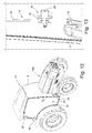
figure 1 is a perspective view of an agricultural tractor on which a preferred embodiment of the cabin according to the present invention is mounted; -
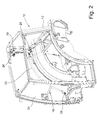
figure 2 is a perspective view of the cabin shown infigure 1 , without the roof and provided with a single covering panel, in particular a door; -
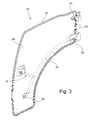
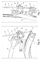
figure 3 is a perspective view, from the inside, of a panel, in particular a door, of the cabin offigure 2 ; -
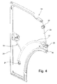
figure 4 is a section view, from the inside, of the door offigure 3 ; -
figure 5 is another section view, from the inside, of the door offigure 3 ; -
figures 6 and 7 are respective section views that show, in a first operative configuration, an adjustment device of a panel of the cabin offigure 2 ; -
figures 8 and 9 are respective section views that show, in a second operative configuration, an adjustment device of a panel of the cabin offigure 2 ; -
figures 10 and 11 are respective section views that show, in a third operative configuration, an adjustment device of a panel of the cabin offigure 2 ; -
figure 12 is a perspective view of an agricultural tractor on which a variant embodiment of the cabin according to the present invention is mounted; andfigure 13 is a section view of an adjustment device of the cabin offigure 12 . - With reference in particular to
figure 1 , a vehicle with an internal combustion engine, in particular an agricultural tractor, is shown, on which a cabin according to the present invention is mounted. The vehicle is wholly indicated withreference numeral 100, whereas the cabin is wholly indicated withreference numeral 10. - Now with reference to
figure 2 , a preferred embodiment of thecabin 10 is shown. Thecabin 10 is provided with aframe 12 configured to be fixed onto the bearing structure of thevehicle 100. A plurality ofpanels 14, for example consisting of one or more doors, a windscreen, a rear window and one or more possible further panels, like for example the roof, is mounted on theframe 12, in a fixed or openable manner. - All of the
panels 14, whether openable or not, are configured so as to maintain thecabin 10 sealingly closed in the operative configuration of thevehicle 100. For this purpose, eachpanel 14, in particular if it is of the openable type, is advantageously provided with at least onesealing gasket 16 that is interposed between such apanel 14 and theframe 12 of thecabin 10. - In detail, with reference for example to
figure 3 , at least part of thepanels 14, typically openable ones including for example the doors of thevehicle 100, is provided with asupport structure 18 configured for constraining therelative panel 14 to theframe 12. In the case of thedoor 14, for example, thesupport structure 18 consists of ahinge group 20, rotatably connected to theframe 12, and of ahandle 22, integral both with thehinge group 20, and with a sheet-like element 24, preferably made entirely from a transparent material, which forms thedoor 14. In this case, therefore, thesupport structure 18 is arranged on the internal surface of therespective door 14 so that thehandle 22 can be grasped from inside thecabin 10. Thehinge group 20 is advantageously configured for rotating therespective door 14 with respect to a vertical axis, or in any case substantially perpendicular to a resting plane of thevehicle 100. - If the
panel 14 consists, for example, of a windscreen or a tilting rear window, of the type commonly mounted on some cabins of farming machines in general, thesupport structure 18 would be configured in a manner suitable for ensuring that the driver has maximum visibility. In the case of a windscreen or tilting rear window, moreover, thehinge group 20 could be configured for rotating such a windscreen or rear window with respect to a horizontal axis, or in any case substantially parallel to a resting plane of thevehicle 100. - According to the invention, between each
panel 14 and therespective support structure 18 one or more slidable connection and adjustment means 26 are interposed that allow a linear displacement of thepanel 14 to be performed with respect to itssupport structure 18 and, thus, allows the position of such apanel 14 to be adjusted with respect to theframe 12 of thecabin 10. In the case of thedoor 14, for example, at least one slidable connection and adjustment means 26, arranged at thehandle 22, and a pair of slidable connection and adjustment means 26, arranged at thehinge group 20, can be provided. - In detail, with reference to the example embodiment shown in
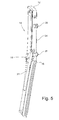
figures 3 to 11 , each slidable connection and adjustment means 26 consists of a threaded bushing provided with ascrew element 28, integral with thedoor 14, and with anut screw element 30, integral with thesupport structure 18 and engageable in sliding coupling with such ascrew element 28. Thescrew element 28 and thenut screw element 30 are configured for sliding along a direction substantially perpendicular to the development plane of thedoor 14, so as to move away or approach such adoor 14 with respect to the door opening formed on theframe 12. However, this does not rule out the possibility of thescrew element 28 being integral with thesupport structure 18 and thenut screw element 30 being integral with thedoor 14, while maintaining the sliding coupling between such ascrew element 28 and such anut screw element 30. - In the example embodiment shown in
figures 3 to 11 thescrew element 28 is integral with thedoor 14 through the interposition of asleeve 32 that engages in a corresponding hole made in thedoor 14 itself. The internal hole of thesleeve 32 has an internal diameter that is greater than the external diameter of thescrew element 28, so as to allow relative movements betweensleeve 32 andscrew element 28 and, thus, obtain a movement (although limited) of thedoor 14 along its development plane. In this way, there is the possibility of adjusting the position of thedoor 14 also in the vertical direction with respect to the door opening formed on theframe 12. - The adjustment of each
single bushing 26 is independent and can be carried out both from inside, and from outside thecabin 10. The rotation of eachbushing 26 thus corresponds to a linear variation of the distance apart of the elements involved in the adjustment, in other words the portion ofpanel 14 on which such abushing 26 is installed and therespective support structure 18. -
Figures 6 and 7 show an operative condition in which thebushing 26 is completely drawn-out. In this operative condition thedoor 14 is in the position of maximum distance with respect to itssupport structure 18 and, therefore, with respect to theframe 12 of thecabin 10. This maximum distance is highlighted by the fact that the sealinggasket 16 of thedoor 14, configured to go into abutment against a corresponding portion offrame 12, is minimally or not at all compressed. -
Figures 8 and 9 show an operative condition in which thebushing 26 is in intermediate position, in other words actuated up to half of its stroke. In this operative condition thedoor 14 is in a position of intermediate distance with respect to itssupport structure 18 and, therefore, with respect to theframe 12 of thecabin 10. This intermediate distance is highlighted by the fact that the sealinggasket 16 of thedoor 14 is compressed by a medium amount. - Finally,
figures 10 and 11 show an operative condition in which thebushing 26 is completely drawn-in. In this operative condition thedoor 14 is in the position of minimum distance with respect to itssupport structure 18 and, therefore, with respect to theframe 12 of thecabin 10. This minimum distance is highlighted by the fact that the sealinggasket 16 of thedoor 14 is in a condition of maximum compression. - Between the two maximum extremes, established by design according to the requirements, the adjustment of each
bushing 26 is continuous and provides for an indefinite number of positions. In any case, in the manufacturing step of thecabin 10, eachbushing 26 can be pre-adjusted in its intermediate position, so that therespective panel 14, whether it is a door or not, adheres to theframe 12 according to the nominal design settings of thecabin 10. -
Figures 12 and 13 show a variant embodiment of thecabin 10, as well as of therespective bushings 26. In this variant embodiment eachbushing 26 is configured to be mounted on asupport structure 18 arranged on the external surface of thepanel 14, in this case the door of thecabin 10. In this variant embodiment, therefore, thehinge group 20 is also arranged on the external surface of thepanel 14 and anexternal handle 22 on which further bushings 26 are possibly mounted may or may not be provided. Even if they are housed on theexternal hinge group 20, thebushings 26 are still able to ensure the adjustment of the distance between thedoor 14 and the relative opening formed in theframe 12 of thecabin 10. - It has thus been seen that the cabin for a vehicle, in particular for an agricultural tractor, according to the present invention achieves the purposes outlined earlier, in particular obtaining the following advantages:
- optimisation of the compression of the sealing gasket of the panels, in particular of the doors;
- sealing of the cabin, avoiding the entry and/or exit of fluids and dusts;
- guaranteed pressurization of the cabin;
- improvement of the quality of the assembly processes;
- compensation of the production tolerances of the different elements of the panels of the cabin, in particular of the doors, with consequent decrease in assembly defects;
- speed of adjustment;
- reduction of repair interventions, at the end of the assembly line, for the adjustments of the doors, which can be carried out quickly already on the assembly line of the cabins.
- The cabin for a vehicle, in particular for an agricultural tractor, of the present invention thus conceived can in any case undergo numerous modifications and variants, all of which are encompassed by the same inventive concept; moreover, all of the details can be replaced by technically equivalent elements. In practice, the materials used, as well as the shapes and sizes, can be whatever according to the technical requirements.
- The scope of protection of the invention is therefore defined by the attached claims.
Claims (9)
- Cabin (10) for a vehicle (100) provided with a frame (12) configured for being fixed on the bearing structure of said vehicle (100), the cabin (10) comprising a plurality of panels (14) mounted on said frame (12), wherein at least part of said panels (14) is provided both with a support structure (18), configured for constraining the relative panel (14) to the frame (12), and at least one sealing gasket (16), which is interposed between said panel (14) and said frame (12) in order to maintain the cabin (10) sealingly closed in the operative configuration of the vehicle (100), between each panel (14) and the respective support structure (18) one or more slidable connection and adjustment means (26) being interposed, which allow performing a linear displacement of the panel (14) with respect to its support structure (18) and, thus, adjusting the position of said panel (14) with respect to the frame (12) of the cabin (10), the cabin (10) being characterised in that each slidable connection and adjustment means (26) consists of a threaded bushing provided with a screw element (28) and with a nut screw element (30) that is engageable in slidable coupling with said screw element (28), said screw element (28) and said nut screw element (30) being configured for sliding along a direction substantially perpendicular to the development plan of the panel (14), so as to move away or approach said panel (14) with respect to the frame (12).
- Cabin (10) according to claim 1, characterised in that said screw element (28) is integral with the panel (14) and said nut screw element (30) is integral with the support structure (18).
- Cabin (10) according to claim 2, characterised in that said screw element (28) is made integral with the panel (14) by interposing a sleeve (32) that is inserted into a corresponding hole made in said panel (14), the internal hole of the sleeve (32) having an internal diameter greater than the external diameter of the screw element (28), so as to allow relative movements between said sleeve (32) and said screw element (28) and, thus, obtain a movement of the panel (14) along its own development plane.
- Cabin (10) according to claim 1, characterised in that said screw element (28) is integral with the support structure (18) and said nut screw element (30) is integral with the panel (14).
- Cabin (10) according to any claims 1 to 4, characterised in that said plurality of panels (14) is constituted by the doors of said cabin (10).
- Cabin (10) according to claim 5, characterised in that the support structure (18) consists of a hinge group (20), rotatably connected to the frame (12), and of a handle (22), integral both with the hinge group (20) and with a sheet-like element (24) that forms each of said doors (14).
- Cabin (10) according to claim 6, characterised in that it comprises at least one slidable connection and adjustment means (26) arranged at the handle (22) and a pair of slidable connection and adjustment means (26) arranged at the hinge group (20).
- Cabin (10) according to claim 6 or 7, characterised in that the support structure (18) is arranged on the internal surface of the respective door (14), so that the handle (22) can be grasped from inside the cabin (10).
- Cabin (10) according to any claims 1 to 5, characterised in that each slidable connection and adjustment means (26) is configured for being mounted on a support structure (18) arranged on the external surface of the panel (14).
Applications Claiming Priority (1)
| Application Number | Priority Date | Filing Date | Title |
|---|---|---|---|
| ITUB2015A000409A ITUB20150409A1 (en) | 2015-04-22 | 2015-04-22 | CAB FOR A VEHICLE, ESPECIALLY FOR AN AGRICULTURAL TRACTOR. |
Publications (2)
| Publication Number | Publication Date |
|---|---|
| EP3090928A1 true EP3090928A1 (en) | 2016-11-09 |
| EP3090928B1 EP3090928B1 (en) | 2018-03-28 |
Family
ID=53490178
Family Applications (1)
| Application Number | Title | Priority Date | Filing Date |
|---|---|---|---|
| EP16166498.2A Active EP3090928B1 (en) | 2015-04-22 | 2016-04-21 | Cabin for a vehicle, in particular for an agricultural tractor |
Country Status (2)
| Country | Link |
|---|---|
| EP (1) | EP3090928B1 (en) |
| IT (1) | ITUB20150409A1 (en) |
Cited By (1)
| Publication number | Priority date | Publication date | Assignee | Title |
|---|---|---|---|---|
| EP4671451A1 (en) * | 2024-06-27 | 2025-12-31 | Kubota Corporation | WORK MACHINE |
Citations (6)
| Publication number | Priority date | Publication date | Assignee | Title |
|---|---|---|---|---|
| DE2126375A1 (en) | 1971-05-27 | 1972-12-07 | Kettler, Paul Erich, 6361 Ockstadt | Entrance door for tractors, tractors, construction machines and similar vehicles equipped with a convertible top or driver's cab |
| DE2733166A1 (en) * | 1977-07-22 | 1979-02-01 | Kloeckner Humboldt Deutz Ag | VEHICLE DOORS, IN PARTICULAR FOR A DRIVER'S CAB |
| US4956942A (en) * | 1989-06-09 | 1990-09-18 | Textron Inc. | Window adjustment mechanism |
| WO1998016709A1 (en) * | 1996-10-15 | 1998-04-23 | Trim Trends, Inc. | Door cassette for a vehicle and method of assembly |
| EP1332901A2 (en) | 2002-02-02 | 2003-08-06 | Cnh U.K. Limited | Frameless and transparent vehicle door |
| DE112012006544T5 (en) * | 2012-06-18 | 2015-03-05 | Volvo Construction Equipment Ab | Cab protection device for a construction machine |
-
2015
- 2015-04-22 IT ITUB2015A000409A patent/ITUB20150409A1/en unknown
-
2016
- 2016-04-21 EP EP16166498.2A patent/EP3090928B1/en active Active
Patent Citations (6)
| Publication number | Priority date | Publication date | Assignee | Title |
|---|---|---|---|---|
| DE2126375A1 (en) | 1971-05-27 | 1972-12-07 | Kettler, Paul Erich, 6361 Ockstadt | Entrance door for tractors, tractors, construction machines and similar vehicles equipped with a convertible top or driver's cab |
| DE2733166A1 (en) * | 1977-07-22 | 1979-02-01 | Kloeckner Humboldt Deutz Ag | VEHICLE DOORS, IN PARTICULAR FOR A DRIVER'S CAB |
| US4956942A (en) * | 1989-06-09 | 1990-09-18 | Textron Inc. | Window adjustment mechanism |
| WO1998016709A1 (en) * | 1996-10-15 | 1998-04-23 | Trim Trends, Inc. | Door cassette for a vehicle and method of assembly |
| EP1332901A2 (en) | 2002-02-02 | 2003-08-06 | Cnh U.K. Limited | Frameless and transparent vehicle door |
| DE112012006544T5 (en) * | 2012-06-18 | 2015-03-05 | Volvo Construction Equipment Ab | Cab protection device for a construction machine |
Cited By (1)
| Publication number | Priority date | Publication date | Assignee | Title |
|---|---|---|---|---|
| EP4671451A1 (en) * | 2024-06-27 | 2025-12-31 | Kubota Corporation | WORK MACHINE |
Also Published As
| Publication number | Publication date |
|---|---|
| ITUB20150409A1 (en) | 2016-10-22 |
| EP3090928B1 (en) | 2018-03-28 |
Similar Documents
| Publication | Publication Date | Title |
|---|---|---|
| EP3227135B1 (en) | Optimized air control system for vehicles | |
| DE19732225B4 (en) | Motor vehicle door | |
| DE102007061812A1 (en) | Motor vehicle with a spoiler device | |
| EP3090928B1 (en) | Cabin for a vehicle, in particular for an agricultural tractor | |
| EP3556719B1 (en) | Forklift side door | |
| EP1771330B1 (en) | Aircraft door arrangement comprising a pivotable aircraft door | |
| DE102010026268A1 (en) | Vehicle, has camera arranged in radiator cowl and moved between rest position and operating position by swivel mechanism, where camera is extendable from radiator cowl in plane and visible from outside in operating position | |
| DE102009057558A1 (en) | Industrial lorry i.e. counterbalance forklift lorry, has clamps supported at fixed rotation axes and movable hinge axes, where hinge axes are arranged between rotation axes in relation to closing position of door | |
| EP2562342A2 (en) | Vehicle door fluid swivel drive | |
| DE102015207562A1 (en) | Roof integrated tailgate drive | |
| EP2915701B1 (en) | Rear view mirror adjustment assembly for vehicles, in particular for commercial vehicles, and rear view mirror with same | |
| CN205239658U (en) | Two cabin cover assemblies and car | |
| DE19821075A1 (en) | Vehicle door | |
| EP2500497B1 (en) | Work vehicle hood actuator | |
| DE102012109881A1 (en) | Structure for the intake of outside air of a vehicle | |
| DE102015013707A1 (en) | Vehicle with a liftable hood | |
| US20040056506A1 (en) | Retractable top system for vehicles with movable rear section | |
| EP3269574A1 (en) | Window device | |
| EP3144167B1 (en) | Frame adapter, window insert with a frame adapter and vehicle with a frame adapter | |
| IT201800000653A1 (en) | DEVICE FOR ADJUSTING THE POSITION IN HEIGHT OF A GLASS CARRIED BY A WINDOW REGULATOR OF A MOTOR VEHICLE. | |
| EP4194274A1 (en) | Device for a vehicle and vehicle | |
| EP1716013A1 (en) | Device for actuating at least one pivoted exterior element of a vehicle | |
| CN204355173U (en) | A kind of engineering machinery driving cabin front panel switching mechanism | |
| KR102299049B1 (en) | Power Room Sealing Structure of Heavy Equipment Vehicle | |
| DE102009058973B4 (en) | Motor vehicle with an actuator for a body lid |
Legal Events
| Date | Code | Title | Description |
|---|---|---|---|
| PUAI | Public reference made under article 153(3) epc to a published international application that has entered the european phase |
Free format text: ORIGINAL CODE: 0009012 |
|
| AK | Designated contracting states |
Kind code of ref document: A1 Designated state(s): AL AT BE BG CH CY CZ DE DK EE ES FI FR GB GR HR HU IE IS IT LI LT LU LV MC MK MT NL NO PL PT RO RS SE SI SK SM TR |
|
| AX | Request for extension of the european patent |
Extension state: BA ME |
|
| STAA | Information on the status of an ep patent application or granted ep patent |
Free format text: STATUS: REQUEST FOR EXAMINATION WAS MADE |
|
| 17P | Request for examination filed |
Effective date: 20170508 |
|
| RBV | Designated contracting states (corrected) |
Designated state(s): AL AT BE BG CH CY CZ DE DK EE ES FI FR GB GR HR HU IE IS IT LI LT LU LV MC MK MT NL NO PL PT RO RS SE SI SK SM TR |
|
| RAP1 | Party data changed (applicant data changed or rights of an application transferred) |
Owner name: SAME DEUTZ-FAHR ITALIA S.P.A. |
|
| RIC1 | Information provided on ipc code assigned before grant |
Ipc: E02F 9/16 20060101ALI20170901BHEP Ipc: B62D 33/06 20060101AFI20170901BHEP Ipc: E02F 9/08 20060101ALI20170901BHEP Ipc: B60J 5/04 20060101ALI20170901BHEP |
|
| GRAP | Despatch of communication of intention to grant a patent |
Free format text: ORIGINAL CODE: EPIDOSNIGR1 |
|
| STAA | Information on the status of an ep patent application or granted ep patent |
Free format text: STATUS: GRANT OF PATENT IS INTENDED |
|
| RAP1 | Party data changed (applicant data changed or rights of an application transferred) |
Owner name: SAME DEUTZ-FAHR ITALIA S.P.A. |
|
| INTG | Intention to grant announced |
Effective date: 20171018 |
|
| GRAS | Grant fee paid |
Free format text: ORIGINAL CODE: EPIDOSNIGR3 |
|
| GRAA | (expected) grant |
Free format text: ORIGINAL CODE: 0009210 |
|
| STAA | Information on the status of an ep patent application or granted ep patent |
Free format text: STATUS: THE PATENT HAS BEEN GRANTED |
|
| AK | Designated contracting states |
Kind code of ref document: B1 Designated state(s): AL AT BE BG CH CY CZ DE DK EE ES FI FR GB GR HR HU IE IS IT LI LT LU LV MC MK MT NL NO PL PT RO RS SE SI SK SM TR |
|
| REG | Reference to a national code |
Ref country code: GB Ref legal event code: FG4D |
|
| REG | Reference to a national code |
Ref country code: CH Ref legal event code: EP |
|
| REG | Reference to a national code |
Ref country code: AT Ref legal event code: REF Ref document number: 983146 Country of ref document: AT Kind code of ref document: T Effective date: 20180415 |
|
| REG | Reference to a national code |
Ref country code: IE Ref legal event code: FG4D |
|
| REG | Reference to a national code |
Ref country code: DE Ref legal event code: R096 Ref document number: 602016002185 Country of ref document: DE |
|
| REG | Reference to a national code |
Ref country code: FR Ref legal event code: PLFP Year of fee payment: 3 |
|
| PG25 | Lapsed in a contracting state [announced via postgrant information from national office to epo] |
Ref country code: NO Free format text: LAPSE BECAUSE OF FAILURE TO SUBMIT A TRANSLATION OF THE DESCRIPTION OR TO PAY THE FEE WITHIN THE PRESCRIBED TIME-LIMIT Effective date: 20180628 Ref country code: FI Free format text: LAPSE BECAUSE OF FAILURE TO SUBMIT A TRANSLATION OF THE DESCRIPTION OR TO PAY THE FEE WITHIN THE PRESCRIBED TIME-LIMIT Effective date: 20180328 Ref country code: LT Free format text: LAPSE BECAUSE OF FAILURE TO SUBMIT A TRANSLATION OF THE DESCRIPTION OR TO PAY THE FEE WITHIN THE PRESCRIBED TIME-LIMIT Effective date: 20180328 Ref country code: HR Free format text: LAPSE BECAUSE OF FAILURE TO SUBMIT A TRANSLATION OF THE DESCRIPTION OR TO PAY THE FEE WITHIN THE PRESCRIBED TIME-LIMIT Effective date: 20180328 |
|
| REG | Reference to a national code |
Ref country code: NL Ref legal event code: MP Effective date: 20180328 |
|
| REG | Reference to a national code |
Ref country code: LT Ref legal event code: MG4D |
|
| PG25 | Lapsed in a contracting state [announced via postgrant information from national office to epo] |
Ref country code: BG Free format text: LAPSE BECAUSE OF FAILURE TO SUBMIT A TRANSLATION OF THE DESCRIPTION OR TO PAY THE FEE WITHIN THE PRESCRIBED TIME-LIMIT Effective date: 20180628 Ref country code: RS Free format text: LAPSE BECAUSE OF FAILURE TO SUBMIT A TRANSLATION OF THE DESCRIPTION OR TO PAY THE FEE WITHIN THE PRESCRIBED TIME-LIMIT Effective date: 20180328 Ref country code: SE Free format text: LAPSE BECAUSE OF FAILURE TO SUBMIT A TRANSLATION OF THE DESCRIPTION OR TO PAY THE FEE WITHIN THE PRESCRIBED TIME-LIMIT Effective date: 20180328 Ref country code: LV Free format text: LAPSE BECAUSE OF FAILURE TO SUBMIT A TRANSLATION OF THE DESCRIPTION OR TO PAY THE FEE WITHIN THE PRESCRIBED TIME-LIMIT Effective date: 20180328 Ref country code: GR Free format text: LAPSE BECAUSE OF FAILURE TO SUBMIT A TRANSLATION OF THE DESCRIPTION OR TO PAY THE FEE WITHIN THE PRESCRIBED TIME-LIMIT Effective date: 20180629 |
|
| PG25 | Lapsed in a contracting state [announced via postgrant information from national office to epo] |
Ref country code: NL Free format text: LAPSE BECAUSE OF FAILURE TO SUBMIT A TRANSLATION OF THE DESCRIPTION OR TO PAY THE FEE WITHIN THE PRESCRIBED TIME-LIMIT Effective date: 20180328 Ref country code: PL Free format text: LAPSE BECAUSE OF FAILURE TO SUBMIT A TRANSLATION OF THE DESCRIPTION OR TO PAY THE FEE WITHIN THE PRESCRIBED TIME-LIMIT Effective date: 20180328 Ref country code: EE Free format text: LAPSE BECAUSE OF FAILURE TO SUBMIT A TRANSLATION OF THE DESCRIPTION OR TO PAY THE FEE WITHIN THE PRESCRIBED TIME-LIMIT Effective date: 20180328 Ref country code: AL Free format text: LAPSE BECAUSE OF FAILURE TO SUBMIT A TRANSLATION OF THE DESCRIPTION OR TO PAY THE FEE WITHIN THE PRESCRIBED TIME-LIMIT Effective date: 20180328 Ref country code: IT Free format text: LAPSE BECAUSE OF FAILURE TO SUBMIT A TRANSLATION OF THE DESCRIPTION OR TO PAY THE FEE WITHIN THE PRESCRIBED TIME-LIMIT Effective date: 20180328 Ref country code: RO Free format text: LAPSE BECAUSE OF FAILURE TO SUBMIT A TRANSLATION OF THE DESCRIPTION OR TO PAY THE FEE WITHIN THE PRESCRIBED TIME-LIMIT Effective date: 20180328 Ref country code: ES Free format text: LAPSE BECAUSE OF FAILURE TO SUBMIT A TRANSLATION OF THE DESCRIPTION OR TO PAY THE FEE WITHIN THE PRESCRIBED TIME-LIMIT Effective date: 20180328 |
|
| PG25 | Lapsed in a contracting state [announced via postgrant information from national office to epo] |
Ref country code: CZ Free format text: LAPSE BECAUSE OF FAILURE TO SUBMIT A TRANSLATION OF THE DESCRIPTION OR TO PAY THE FEE WITHIN THE PRESCRIBED TIME-LIMIT Effective date: 20180328 Ref country code: SM Free format text: LAPSE BECAUSE OF FAILURE TO SUBMIT A TRANSLATION OF THE DESCRIPTION OR TO PAY THE FEE WITHIN THE PRESCRIBED TIME-LIMIT Effective date: 20180328 Ref country code: SK Free format text: LAPSE BECAUSE OF FAILURE TO SUBMIT A TRANSLATION OF THE DESCRIPTION OR TO PAY THE FEE WITHIN THE PRESCRIBED TIME-LIMIT Effective date: 20180328 |
|
| REG | Reference to a national code |
Ref country code: AT Ref legal event code: MK05 Ref document number: 983146 Country of ref document: AT Kind code of ref document: T Effective date: 20180328 |
|
| REG | Reference to a national code |
Ref country code: BE Ref legal event code: MM Effective date: 20180430 |
|
| PG25 | Lapsed in a contracting state [announced via postgrant information from national office to epo] |
Ref country code: PT Free format text: LAPSE BECAUSE OF FAILURE TO SUBMIT A TRANSLATION OF THE DESCRIPTION OR TO PAY THE FEE WITHIN THE PRESCRIBED TIME-LIMIT Effective date: 20180730 |
|
| REG | Reference to a national code |
Ref country code: DE Ref legal event code: R097 Ref document number: 602016002185 Country of ref document: DE |
|
| REG | Reference to a national code |
Ref country code: IE Ref legal event code: MM4A |
|
| PG25 | Lapsed in a contracting state [announced via postgrant information from national office to epo] |
Ref country code: MC Free format text: LAPSE BECAUSE OF FAILURE TO SUBMIT A TRANSLATION OF THE DESCRIPTION OR TO PAY THE FEE WITHIN THE PRESCRIBED TIME-LIMIT Effective date: 20180328 Ref country code: DK Free format text: LAPSE BECAUSE OF FAILURE TO SUBMIT A TRANSLATION OF THE DESCRIPTION OR TO PAY THE FEE WITHIN THE PRESCRIBED TIME-LIMIT Effective date: 20180328 Ref country code: AT Free format text: LAPSE BECAUSE OF FAILURE TO SUBMIT A TRANSLATION OF THE DESCRIPTION OR TO PAY THE FEE WITHIN THE PRESCRIBED TIME-LIMIT Effective date: 20180328 Ref country code: LU Free format text: LAPSE BECAUSE OF NON-PAYMENT OF DUE FEES Effective date: 20180421 |
|
| PLBE | No opposition filed within time limit |
Free format text: ORIGINAL CODE: 0009261 |
|
| STAA | Information on the status of an ep patent application or granted ep patent |
Free format text: STATUS: NO OPPOSITION FILED WITHIN TIME LIMIT |
|
| PG25 | Lapsed in a contracting state [announced via postgrant information from national office to epo] |
Ref country code: BE Free format text: LAPSE BECAUSE OF NON-PAYMENT OF DUE FEES Effective date: 20180430 |
|
| 26N | No opposition filed |
Effective date: 20190103 |
|
| PG25 | Lapsed in a contracting state [announced via postgrant information from national office to epo] |
Ref country code: IE Free format text: LAPSE BECAUSE OF NON-PAYMENT OF DUE FEES Effective date: 20180421 |
|
| PG25 | Lapsed in a contracting state [announced via postgrant information from national office to epo] |
Ref country code: SI Free format text: LAPSE BECAUSE OF FAILURE TO SUBMIT A TRANSLATION OF THE DESCRIPTION OR TO PAY THE FEE WITHIN THE PRESCRIBED TIME-LIMIT Effective date: 20180328 |
|
| REG | Reference to a national code |
Ref country code: CH Ref legal event code: PL |
|
| PG25 | Lapsed in a contracting state [announced via postgrant information from national office to epo] |
Ref country code: MT Free format text: LAPSE BECAUSE OF NON-PAYMENT OF DUE FEES Effective date: 20180421 Ref country code: LI Free format text: LAPSE BECAUSE OF NON-PAYMENT OF DUE FEES Effective date: 20190430 Ref country code: CH Free format text: LAPSE BECAUSE OF NON-PAYMENT OF DUE FEES Effective date: 20190430 |
|
| PG25 | Lapsed in a contracting state [announced via postgrant information from national office to epo] |
Ref country code: TR Free format text: LAPSE BECAUSE OF FAILURE TO SUBMIT A TRANSLATION OF THE DESCRIPTION OR TO PAY THE FEE WITHIN THE PRESCRIBED TIME-LIMIT Effective date: 20180328 |
|
| PG25 | Lapsed in a contracting state [announced via postgrant information from national office to epo] |
Ref country code: CY Free format text: LAPSE BECAUSE OF FAILURE TO SUBMIT A TRANSLATION OF THE DESCRIPTION OR TO PAY THE FEE WITHIN THE PRESCRIBED TIME-LIMIT Effective date: 20180328 Ref country code: MK Free format text: LAPSE BECAUSE OF NON-PAYMENT OF DUE FEES Effective date: 20180328 Ref country code: HU Free format text: LAPSE BECAUSE OF FAILURE TO SUBMIT A TRANSLATION OF THE DESCRIPTION OR TO PAY THE FEE WITHIN THE PRESCRIBED TIME-LIMIT; INVALID AB INITIO Effective date: 20160421 |
|
| PG25 | Lapsed in a contracting state [announced via postgrant information from national office to epo] |
Ref country code: IS Free format text: LAPSE BECAUSE OF FAILURE TO SUBMIT A TRANSLATION OF THE DESCRIPTION OR TO PAY THE FEE WITHIN THE PRESCRIBED TIME-LIMIT Effective date: 20180728 |
|
| GBPC | Gb: european patent ceased through non-payment of renewal fee |
Effective date: 20200421 |
|
| PG25 | Lapsed in a contracting state [announced via postgrant information from national office to epo] |
Ref country code: GB Free format text: LAPSE BECAUSE OF NON-PAYMENT OF DUE FEES Effective date: 20200421 |
|
| P01 | Opt-out of the competence of the unified patent court (upc) registered |
Effective date: 20230502 |
|
| PGFP | Annual fee paid to national office [announced via postgrant information from national office to epo] |
Ref country code: DE Payment date: 20250305 Year of fee payment: 10 |
|
| PGFP | Annual fee paid to national office [announced via postgrant information from national office to epo] |
Ref country code: FR Payment date: 20260309 Year of fee payment: 11 |