EP3090898A1 - Verriegelungsvorrichtung - Google Patents
Verriegelungsvorrichtung Download PDFInfo
- Publication number
- EP3090898A1 EP3090898A1 EP15166387.9A EP15166387A EP3090898A1 EP 3090898 A1 EP3090898 A1 EP 3090898A1 EP 15166387 A EP15166387 A EP 15166387A EP 3090898 A1 EP3090898 A1 EP 3090898A1
- Authority
- EP
- European Patent Office
- Prior art keywords
- locking
- coupling portion
- receptacle
- base
- locking element
- Prior art date
- Legal status (The legal status is an assumption and is not a legal conclusion. Google has not performed a legal analysis and makes no representation as to the accuracy of the status listed.)
- Granted
Links
- 238000010168 coupling process Methods 0.000 claims abstract description 68
- 230000008878 coupling Effects 0.000 claims abstract description 67
- 238000005859 coupling reaction Methods 0.000 claims abstract description 67
- 238000005520 cutting process Methods 0.000 claims description 40
- 230000013011 mating Effects 0.000 claims description 3
- 230000007246 mechanism Effects 0.000 claims description 3
- 238000003306 harvesting Methods 0.000 claims 1
- 238000003780 insertion Methods 0.000 description 5
- 230000037431 insertion Effects 0.000 description 5
- 241001124569 Lycaenidae Species 0.000 description 3
- 238000000034 method Methods 0.000 description 3
- 230000008569 process Effects 0.000 description 3
- 238000004519 manufacturing process Methods 0.000 description 2
- 239000002184 metal Substances 0.000 description 2
- 230000008901 benefit Effects 0.000 description 1
- 230000000295 complement effect Effects 0.000 description 1
- 238000010276 construction Methods 0.000 description 1
- 230000001419 dependent effect Effects 0.000 description 1
- 238000013461 design Methods 0.000 description 1
- 238000011161 development Methods 0.000 description 1
- 230000018109 developmental process Effects 0.000 description 1
- 238000009826 distribution Methods 0.000 description 1
- 238000005516 engineering process Methods 0.000 description 1
- 230000002349 favourable effect Effects 0.000 description 1
- 239000004459 forage Substances 0.000 description 1
- 230000001771 impaired effect Effects 0.000 description 1
- 238000012423 maintenance Methods 0.000 description 1
- 230000008439 repair process Effects 0.000 description 1
- 238000012546 transfer Methods 0.000 description 1
Images


Classifications
-
- B—PERFORMING OPERATIONS; TRANSPORTING
- B60—VEHICLES IN GENERAL
- B60P—VEHICLES ADAPTED FOR LOAD TRANSPORTATION OR TO TRANSPORT, TO CARRY, OR TO COMPRISE SPECIAL LOADS OR OBJECTS
- B60P3/00—Vehicles adapted to transport, to carry or to comprise special loads or objects
- B60P3/06—Vehicles adapted to transport, to carry or to comprise special loads or objects for carrying vehicles
- B60P3/07—Vehicles adapted to transport, to carry or to comprise special loads or objects for carrying vehicles for carrying road vehicles
- B60P3/073—Vehicle retainers
-
- A—HUMAN NECESSITIES
- A01—AGRICULTURE; FORESTRY; ANIMAL HUSBANDRY; HUNTING; TRAPPING; FISHING
- A01D—HARVESTING; MOWING
- A01D75/00—Accessories for harvesters or mowers
- A01D75/002—Carriers for the transport of harvesters or mowers
-
- B—PERFORMING OPERATIONS; TRANSPORTING
- B60—VEHICLES IN GENERAL
- B60P—VEHICLES ADAPTED FOR LOAD TRANSPORTATION OR TO TRANSPORT, TO CARRY, OR TO COMPRISE SPECIAL LOADS OR OBJECTS
- B60P7/00—Securing or covering of load on vehicles
- B60P7/06—Securing of load
- B60P7/08—Securing to the vehicle floor or sides
Definitions
- the present invention relates to a locking device for locking a to be transported on a transport vehicle cutting unit for a harvester against a support frame of the transport vehicle, with an example schneidwerk pasen coupling portion and an example vehicle-side receptacle for the coupling portion, which can be brought together in a locking engagement.
- Cutting units for combine harvesters, forage harvesters and the like are generally designed as intent cutting units and have an unacceptably large width for road traffic. Therefore, special transport vehicles are required for transporting cutting units away from a field.
- so-called "cutting unit carriages" are used to transport cutting units.
- a cutting carriage is a trailer on which a cutting unit is to accommodate in longitudinal direction and which can be pulled for example by the associated harvester itself.
- the support frame of such a transport vehicle may comprise different support elements, supports and the like in various numbers. Accordingly, the term "support frame” should not be limited to a simple closed frame construction.
- a locking device of the type mentioned ensures at a cutting unit carriage or a similar transport vehicle that the cutting unit to be transported does not slip, tilt or even fall during transport.
- the coupling portion and the Receiving be provided with respective through holes, through which a separate plug element is inserted laterally by aligned alignment. This insertion can prove difficult or troublesome in practice. In addition, the separate plug element can easily get lost.
- the coupling portion has a base, a shaft extending from the base and a head projecting from the shaft, and that the receptacle has a stop surface for the base of the coupling portion and an opening for passing at least the head of the coupling portion in one Implementing direction, wherein on the receptacle, a locking element is provided, which is movable between a release position and a locking position and is adapted to engage behind the guided through the opening head of the coupling portion in the locking position.
- the locking element of the coupling portion Due to the gripping behind of the head by the locking element of the coupling portion is positively held and accordingly reliably in the recording.
- the locking element when the locking element is in the release position, the head of the coupling section guided through the opening is not engaged behind and the coupling section can be guided out of the receptacle counter to the direction of passage.
- the cutting mechanism is thus either positively held on the support frame or detached from this and therefore removable.
- the stop surface provided on the receptacle for the base of the coupling portion facilitates the locking operation in that a user does not have to pay attention to maintaining a predetermined insertion depth of the coupling portion. Rather, insertion of the coupling portion into the receptacle beyond the predetermined amount by the stop is excluded.
- Another advantage of the invention is that no losable loose parts are required for locking.
- the locking element can be mounted pivotably between the release position and the locking position on a base portion of the receptacle, preferably about a pivot axis extending parallel to the direction of passage. This allows a particularly simple and compact design. In particular, no complex linear guides are necessary in this case.
- a special embodiment of the invention provides that the locking element is designed like a hook or has a hook-like holding portion. In principle, a displaceable mounting of the locking element on the base could also be provided instead of a pivotable mounting.
- the locking element on an elongated and open at one longitudinal end recess, the opposite boundary edges engage behind the head of the coupling portion on both sides when the locking element is in the locked position.
- the width of this recess corresponds approximately to the thickness of the shank.
- the recess may in particular be designed as a one-sided open slot, so that there is a fork-like basic shape of the locking element. In the case of a pivotable locking element, it is preferred that the recess is curved.
- the two-sided engagement behind ensures a particularly reliable fixation of the coupling section in the receptacle.
- a locking element with a slot open on one side is also simple and inexpensive to produce.
- the locking element may generally have a flat basic shape, so for example be plate-like. This is manufacturing technology particularly favorable.
- the planar locking element can be manufactured as a stamped and / or lasered sheet metal part. A tongue-like widening of the planar locking element can in this case form a grip section for actuating the locking element. There are then no complex separate actuators required.
- a preferred embodiment of the invention provides that the head of the coupling portion is at least substantially spherical. Such a rounded head facilitates the movement of the locking element in the direction of the locking position and prevents "sticking" on edges or heels.
- the ball head is particularly easy to slide along the insertion bevels of the recording and so further simplify the locking process.
- the shaft of the coupling portion may be at least substantially cylindrical in order to enable simple and cost-effective production.
- the receptacle on two mutually inclined abutment surfaces which are designed for a system corresponding to each other inclined mating surfaces of the base of the coupling portion.
- Such stop surfaces form chamfers and facilitate the correct positioning of the coupling portion.
- the mutually inclined abutment surfaces can be arranged arrow-like with respect to the direction of execution, so that they cause a self-centering of the coupling portion relative to the receptacle.
- the locking element in the release position and / or in the locked position can be locked, in particular by means of an adjustable locking bolt.
- an adjustable locking bolt may be provided on the receptacle, a recess into which a lock bolt movably mounted on the locking bolt is inserted.
- the locking pin is adjustable by actuation of a securing element such as a safety lever, in particular wherein the securing element can be fixed at least in a securing position.
- the coupling portion or the receptacle is designed for a releasable attachment to the cutting unit.
- the schneidtechnik suede locking component z. B. be removed for maintenance and repair purposes.
- z. B. retaining tabs or retaining flanges may be provided with corresponding mounting holes on the coupling portion or on the recording.
- the coupling portion forms a cutting mechanism-side locking component, while the receptacle forms a vehicle-side locking component of the device according to the invention.
- the coupling portion could be designed for attachment to the transport vehicle, while the receptacle is designed for attachment to the cutting unit.
- a further embodiment of the invention provides that a support for the coupling portion and / or at least one further portion of the cutting unit is arranged on the receptacle, in particular wherein the support mounted in the State of the locking device is at least partially inclined relative to the horizontal.
- a support serves to support and / or guide the cutting unit during the locking process and thus facilitates the insertion of the coupling portion in the receptacle.
- the support can be designed in particular as a simple support plate. On a relative to the horizontal inclined portion of the support, the cutting unit during loading of the transport vehicle with the cutting mechanism or during the coupling process slide down until the coupling portion comes into engagement with the recording.
- the base of the coupling portion has a counter-surface formed to rest on the support.
- a full-surface contact of the counter surface may be provided on the support by the counter surface is designed to be complementary to the support.
- the base of the coupling portion may comprise at least one hollow profile, in particular a rectangular tube.
- the weight of the coupling portion can be kept low by using a hollow profile, without the stability is unduly impaired.
- the invention also relates to a transport vehicle for reapers of harvesters with a chassis, a support frame and a locking device for locking a transportable cutting unit relative to the support frame, wherein the locking device is formed as described above.
- the locking device allows a reliable backup of the cutting unit on the transport vehicle during any transport and transfer trips.
- the transport vehicle is designed as a trailer.
- a trailer can z. B. are pulled by the associated harvester, so that the use of a motorized transport vehicle is generally not necessary.
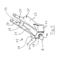
- the in Fig. 1-3 illustrated coupling portion 11 forms the schneidwerk brieflyen part of a Fig. 8 completely shown locking device 13 for locking a cutting unit on a transport vehicle.
- the coupling portion 11 comprises a base 15, a neck or shank 17 extending from the base 15, and a head 19 projecting from the shank 17.
- the shank 17 is cylindrically shaped while the head 19 is a ball head is.
- the base 15 comprises a hollow profile in the form of an elongate rectangular tube 21.
- Plate-like lateral webs 23 are attached to two opposite longitudinal sides of the rectangular tube 21.
- a functional portion 29 which carries the here formed integrally with the shaft 17 head 19 and two with respect to a shaft axis A of the shaft 17th has inclined inclined surfaces 31.
- the inclined surfaces 31 are arrow-like inclined to each other as shown.
- the head 19 facing away from the end of the rectangular tube 21 is covered by a stiffening portion 33 which is connected to the side bars 23.
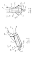
- the functional portion 29 and the stiffening portion 33 may be formed by a common edge plate or by a plurality of interconnected edge plates. As in Fig. 2 can be seen, intersect the longitudinal axis L of the rectangular tube 21 and the shaft axis A.
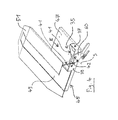
- the Fig. 4-7 show a recording 35 for the in Fig. 1-3 illustrated coupling portion 11, the vehicle-side part of in Fig. 8 shown locking device 13 forms.
- the receptacle 35 comprises a base section 37 which defines a flat end face 39 and two inclined surfaces 41 facing away from one another in the manner of an arrow and facing away from the end face 39. Between the two inclined surfaces 41 is a gap which has an opening 42 for passing the head 19 (FIG. Fig. 1 ) of the coupling portion 11 in a direction of passage E forms.
- the receptacle 35 is located at the edge of a support and guide plate 45, which forms a support for the cutting unit to be transported.
- the support and guide plate 45 has a first plate portion 47 and a relation to the first plate portion 47 extended second plate portion 49, which define a common support plane.
- an extension 51 At an end facing away from the receptacle 35 of the second plate portion 49 is an extension 51, which is angled relative to the second plate portion 49.
- the extended second plate portion 49 serves as a support for a support tube, not shown, conventional cutting units.
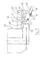
- the unit formed by the support and guide plate 45 and the receptacle 35 is designed for attachment to the support frame of a transport vehicle such as a cutting carriage, of which in Fig. 8 only the part of a longitudinal member 70 is shown.
- the bearing plane defined by the first plate section 47 and the second plate section 49 is inclined relative to the horizontal, preferably by 15 ° to 30 ° and particularly preferably by 20 ° to 25 °.
- the attachment of the receptacle 35 on the support frame can be done via the support and guide plate 45.
- the support and guide plate 45 can be mounted on the underside of at least two bearing points by means of suitable bearing blocks on the support frame.
- the support and guide plate 45 is mounted vertically adjustable on at least one bearing point on the support frame, for example by means of a threaded spindle, so that the inclination angle of the support plane can be adapted to the particular application if necessary.
- a locking element 60 is articulated so that it is pivotable about a pivot axis S between a release position and a locking position.
- the pivot axis S extends in the illustrated embodiment, parallel to the feedthrough direction E.
- the locking element 60 has a plate-like shape and is preferably designed as a simple punched or laser plate. Furthermore, the locking element 60 has a curved running, one-sided open recess 61 (FIG. Fig. 7 ) on. This recess 61 is tapered towards the closed end.
- the in Fig. 7 Above the recess 61 located portion of the locking element 60 forms a hook 62nd
- a narrow, tongue-like extension 63 of the locking element 60 is shaped so that it is easily grasped by an operator and as an operating lever for manually pivoting the locking element 60 between the head 19 through the opening 42 by passing the release position and the in Fig. 8 shown, the head 19 engaging behind bolt position can be used.
- Fig. 8 in contrast to Fig. 4-7 Figure 4 shows a variant in which the locking element 60 is to be pivoted clockwise rather than counterclockwise to move it into the locking position.
- a locking device 64 For locking the locking element 60 as required in the locked position, a locking device 64 is provided which has a locking bolt 65 displaceably guided on the locking element 60 and an eccentric lever 66.
- the locking pin 65 or index pin can be inserted into one of two existing in the end face 39 of the base portion 37 recesses 67, so as to set the locking element 60 in the locked position on the base portion 37.
- the eccentric lever 66 By actuating the eccentric lever 66, the locking pin 65 can be selectively moved into the respective recess 67 and out of the recess 67 out become.
- a curved surface provided on the eccentric lever 66 serves to clamp the eccentric lever 66 in the arresting position, as is generally known.
- Fig. 5 It can be seen that the two recesses 67 are arranged symmetrically with respect to the opening 42.
- the locking element 60 can both left-hand as in Fig. 4 shown as well as right-closing as in Fig. 8 shown mounted on the base portion 37, wherein one of the recesses 67 is used for engagement of the locking pin 65 depending on the type of mounting.
- a cutter on the support frame of a transport vehicle preferably at least two locking devices 13 are provided per cutting to ensure a secure fit and in particular to avoid unwanted tilting of the cutting unit. Furthermore, it is preferable to position the locking devices 13 such that they are visible from the driver's cab of the harvester and not hidden.
- the coupling portion 11 is screwed using the side bars 23 on a support beam 75 of the cutting unit. On the support beam 75 corresponding fastening tabs 77 are provided for this purpose, for example, welded.
- the cutting unit For transport, the cutting unit is moved by means of the associated harvester to the transport vehicle and lowered until appropriate areas of the cutting floor sit on the support and guide plates 45. In this case, too, mating surfaces 78 formed at the respective bases 15 of the coupling sections 11 (see FIG. Fig. 2 ) to rest on the support and guide plates 45. With continued lowering of the cutting unit this slides on the inclined plane of the support and guide plates 45 down, each of the head 19 of the coupling portion 11 in the direction E through the opening 42 of the receptacle 35th to be led. Should not the head 19 on exactly the opening 42 to be aligned, it slides along one of the inclined surfaces 41 and is automatically moved to the opening 42 towards. The spherical shape of the head 19 facilitates this sliding process. Finally, the inclined surfaces 31 of the coupling portion 11 abut against the inclined surfaces 41 of the receptacle 35, due to the corresponding orientation substantially over the entire surface. In this state, the shaft 17 is just in the opening 42.
- the locking element 60 is now grasped at the extension 63 and pivoted into the locking position, wherein the shaft 17 enters the recess 61 and the head 19 is thus engaged behind by the boundary edges of the recess 61. This condition is in Fig. 8 shown. Finally, the locking element 60 is fixed by actuating the locking device 64 in the locked position.
- the invention enables a secure, positive locking of cutting units on transport vehicles such as cutting carriage, the locking and unlocking is simple and intuitive to carry out.
Landscapes
- Engineering & Computer Science (AREA)
- Transportation (AREA)
- Mechanical Engineering (AREA)
- Health & Medical Sciences (AREA)
- Public Health (AREA)
- Life Sciences & Earth Sciences (AREA)
- Environmental Sciences (AREA)
- Fittings On The Vehicle Exterior For Carrying Loads, And Devices For Holding Or Mounting Articles (AREA)
Abstract
Description
- Die vorliegende Erfindung betrifft eine Verriegelungsvorrichtung zum Verriegeln eines auf einem Transportfahrzeug zu transportierenden Schneidwerks für eine Erntemaschine gegenüber einem Tragrahmen des Transportfahrzeugs, mit einem beispielsweise schneidwerkseitigen Kupplungsabschnitt und einer beispielsweise fahrzeugseitigen Aufnahme für den Kupplungsabschnitt, welche miteinander in einen verriegelnden Eingriff bringbar sind.
- Schneidwerke für Mähdrescher, Feldhäcksler und dergleichen sind im Allgemeinen als Vorsatzschneidwerke ausgeführt und weisen eine für den Straßenverkehr unzulässig große Breite auf. Zum Transport von Schneidwerken abseits eines Feldes sind daher spezielle Transportfahrzeuge erforderlich. Beispielsweise werden so genannte "Schneidwerkswagen" zum Transport von Schneidwerken verwendet. Bei einem Schneidwerkswagen handelt es sich um einen Anhänger, auf welchem ein Schneidwerk in Längsausrichtung unterzubringen ist und welcher beispielsweise von der zugehörigen Erntemaschine selbst gezogen werden kann. Der Tragrahmen eines solchen Transportfahrzeugs kann je nach Anwendung unterschiedliche Stützelemente, Auflagen und dergleichen in verschiedener Anzahl umfassen. Demgemäß soll der Begriff "Tragrahmen" nicht auf eine einfache geschlossene Rahmenkonstruktion beschränkt sein.
- Eine Verriegelungsvorrichtung der eingangs genannten Art sorgt bei einem Schneidwerkswagen oder einem ähnlichen Transportfahrzeug dafür, dass das zu transportierende Schneidwerk während des Transports nicht verrutscht, verkippt oder gar herabfällt. Zu diesem Zweck können der Kupplungsabschnitt und die Aufnahme mit jeweiligen Durchgangslöchern versehen sein, durch welche nach miteinander fluchtender Ausrichtung ein separates Steckelement seitlich hindurchgesteckt wird. Dieses Hindurchstecken kann sich in der Praxis als schwierig oder lästig erweisen. Außerdem kann das separate Steckelement leicht abhandenkommen.
- Es ist eine Aufgabe der Erfindung, eine zuverlässige und leicht bedienbare Verriegelungsvorrichtung für Schneidwerk-Transportfahrzeuge anzugeben.
- Die Lösung der Aufgabe erfolgt durch eine Verriegelungsvorrichtung mit den Merkmalen des Anspruchs 1.
- Die Erfindung sieht vor, dass der Kupplungsabschnitt eine Basis, einen sich von der Basis erstreckenden Schaft und einen gegenüber dem Schaft auskragenden Kopf aufweist, und dass die Aufnahme eine Anschlagfläche für die Basis des Kupplungsabschnitts und eine Öffnung zum Durchführen zumindest des Kopfes des Kupplungsabschnitts in einer Durchführrichtung aufweist, wobei an der Aufnahme ein Riegelelement vorgesehen ist, welches zwischen einer Freigabestellung und einer Riegelstellung beweglich ist und dazu ausgebildet ist, in der Riegelstellung den durch die Öffnung hindurchgeführten Kopf des Kupplungsabschnitts zu hintergreifen.
- Aufgrund des Hintergreifens des Kopfes durch das Riegelelement wird der Kupplungsabschnitt formschlüssig und dementsprechend zuverlässig in der Aufnahme gehalten. Wenn sich das Riegelelement hingegen in der Freigabestellung befindet, wird der durch die Öffnung hindurchgeführte Kopf des Kupplungsabschnitts nicht hintergriffen und der Kupplungsabschnitt kann entgegen der Durchführrichtung aus der Aufnahme herausgeführt werden. Je nach Stellung des Riegelelements ist das Schneidwerk also entweder formschlüssig am Tragrahmen gehalten oder von diesem gelöst und daher entnehmbar. Die an der Aufnahme vorgesehene Anschlagfläche für die Basis des Kupplungsabschnitts erleichtert den Verriegelungsvorgang insofern, als ein Benutzer nicht auf das Einhalten einer vorgegebenen Einführtiefe des Kupplungsabschnitts achten muss. Vielmehr ist ein Einführen des Kupplungsabschnitts in die Aufnahme über das durch den Anschlag vorgegebene Maß hinaus ausgeschlossen. Ein weiterer Vorteil der Erfindung besteht darin, dass zum Verriegeln keine verlierbaren Losteile erforderlich sind.
- Das Riegelelement kann zwischen der Freigabestellung und der Riegelstellung verschwenkbar an einem Basisabschnitt der Aufnahme gelagert sein, vorzugsweise um eine parallel zu der Durchführrichtung verlaufende Schwenkachse. Dies ermöglicht eine besonders einfache und kompakte Konstruktion. Insbesondere sind hierbei keine aufwändigen Linearführungen notwendig. Eine spezielle Ausführungsform der Erfindung sieht vor, dass das Riegelelement hakenartig gestaltet ist oder einen hakenartigen Halteabschnitt aufweist. Anstelle einer schwenkbaren Lagerung könnte grundsätzlich auch eine verschiebbare Lagerung des Riegelelements an der Basis vorgesehen sein.
- Gemäß einer Ausführungsform der Erfindung weist das Riegelelement eine längliche und an einem Längsende offene Aussparung auf, deren gegenüberliegende Begrenzungsränder den Kopf des Kupplungsabschnitts zweiseitig hintergreifen, wenn sich das Riegelelement in der Riegelstellung befindet. Vorzugsweise entspricht die Breite dieser Aussparung etwa der Dicke des Schaftes. Die Aussparung kann insbesondere als einseitig offener Schlitz ausgeführt sein, sodass sich eine gabelartige Grundform des Riegelelements ergibt. Im Falle eines verschwenkbaren Riegelelements ist es bevorzugt, dass die Aussparung gekrümmt verläuft. Das zweiseitige Hintergreifen sorgt für eine besonders zuverlässige Fixierung des Kupplungsabschnitts in der Aufnahme. Ein Riegelelement mit einem einseitig offenen Schlitz ist zudem einfach und kostengünstig herstellbar.
- Das Riegelelement kann allgemein eine flächige Grundform aufweisen, also zum Beispiel plattenartig ausgebildet sein. Dies ist herstellungstechnisch besonders günstig. Insbesondere kann das flächige Riegelelement als gestanztes und/oder gelasertes Blechteil gefertigt sein. Eine zungenartige Erweiterung des flächigen Riegelelements kann hierbei einen Griffabschnitt zum Betätigen des Riegelelements bilden. Es sind dann keine aufwändigen separaten Betätigungselemente erforderlich.
- Eine bevorzugte Ausgestaltung der Erfindung sieht vor, dass der Kopf des Kupplungsabschnitts zumindest im Wesentlichen kugelförmig ist. Ein solcher abgerundeter Kopf erleichtert das Bewegen des Riegelelements in Richtung der Riegelstellung und verhindert ein "Hängenbleiben" an Kanten oder Absätzen. Der Kugelkopf kann besonders leicht an Einführschrägen der Aufnahme entlanggleiten und so den Verriegelungsvorgang weiter vereinfachen.
- Der Schaft des Kupplungsabschnitts kann zumindest im Wesentlichen zylindrisch sein, um eine einfache und kostengünstige Fertigung zu ermöglichen.
- Gemäß einer weiteren Ausführungsform der Erfindung weist die Aufnahme zwei zueinander geneigte Anschlagflächen auf, welche für eine Anlage entsprechend zueinander geneigter Gegenflächen der Basis des Kupplungsabschnitts ausgebildet sind. Solche Anschlagflächen bilden Einführschrägen und erleichtern das korrekte Positionieren des Kupplungsabschnitts.
- Insbesondere können die zueinander geneigten Anschlagflächen in Bezug auf die Durchführrichtung pfeilartig angeordnet sein, sodass sie eine Selbstzentrierung des Kupplungsabschnitts relativ zu der Aufnahme bewirken.
- Gemäß einer speziellen Ausgestaltung der Erfindung ist das Riegelelement in der Freigabestellung und/oder in der Riegelstellung arretierbar, insbesondere mittels eines verstellbaren Arretierbolzens. Hierdurch wird ein unbeabsichtigtes Lösen der Verriegelung verhindert. Beispielsweise kann an der Aufnahme eine Ausnehmung vorgesehen sein, in welche ein am Riegelelement beweglich gelagerter Arretierbolzen einführbar ist. Vorzugsweise ist der Arretierbolzen durch Betätigung eines Sicherungselements wie eines Sicherungshebels verstellbar, insbesondere wobei das Sicherungselement zumindest in einer Sicherungsstellung festlegbar ist. Diese Ausgestaltung ermöglicht eine besonders zuverlässige Verriegelung eines Schneidwerks am Transportfahrzeug, da der Kupplungsabschnitt durch das Riegelelement sicherbar ist, das Riegelelement durch den Arretierbolzen sicherbar ist und der Arretierbolzen durch das festlegbare Sicherungselement sicherbar ist.
- Bevorzugt ist der Kupplungsabschnitt oder die Aufnahme für eine lösbare Befestigung am Schneidwerk ausgebildet. Dies ermöglicht bei Bedarf ein Nachrüsten bestehender Schneidwerke mit entsprechenden Kupplungsabschnitten oder Aufnahmen. Außerdem kann bei einer solchen Ausgestaltung die schneidwerkseitige Verriegelungskomponente z. B. für Wartungs- und Reparaturzwecke abgenommen werden. Um eine lösbare Befestigung zu ermöglichen, können z. B. Haltelaschen oder Halteflansche mit entsprechenden Befestigungslöchern am Kupplungsabschnitt oder an der Aufnahme vorgesehen sein.
- Vorzugsweise bildet der Kupplungsabschnitt eine schneidwerkseitige Verriegelungskomponente, während die Aufnahme eine fahrzeugseitige Verriegelungskomponente der erfindungsgemäßen Vorrichtung bildet. Grundsätzlich könnte jedoch auch der Kupplungsabschnitt zur Befestigung am Transportfahrzeug ausgebildet sein, während die Aufnahme zur Befestigung am Schneidwerk ausgebildet ist.
- Eine weitere Ausführungsform der Erfindung sieht vor, dass an der Aufnahme eine Auflage für den Kupplungsabschnitt und/oder wenigstens einen weiteren Abschnitt des Schneidwerks angeordnet ist, insbesondere wobei die Auflage im montierten Zustand der Verriegelungsvorrichtung wenigstens bereichsweise gegenüber der Horizontalen geneigt ist. Eine solche Auflage dient zum Stützen und/oder Führen des Schneidwerks während des Verriegelungsvorgangs und erleichtert so das Einführen des Kupplungsabschnitts in die Aufnahme. Die Auflage kann insbesondere als einfache Stützplatte ausgeführt sein. Auf einem gegenüber der Horizontalen geneigten Abschnitt der Auflage kann das Schneidwerk während des Beladens des Transportfahrzeugs mit dem Schneidwerk bzw. während des Kupplungsvorgangs herabgleiten, bis der Kupplungsabschnitt in einen Eingriff mit der Aufnahme gelangt.
- Es kann vorgesehen sein, dass die Basis des Kupplungsabschnitts eine zum Aufliegen auf der Auflage ausgebildete Gegenfläche aufweist. Insbesondere kann zur besseren Kraftverteilung ein vollflächiges Aufliegen der Gegenfläche auf der Auflage vorgesehen sein, indem die Gegenfläche komplementär zu der Auflage gestaltet ist.
- Die Basis des Kupplungsabschnitts kann wenigstens ein Hohlprofil, insbesondere ein Rechteckrohr, umfassen. Das Gewicht des Kupplungsabschnitts kann durch Verwendung eines Hohlprofils gering gehalten werden, ohne dass die Stabilität übermäßig beeinträchtigt ist.
- Die Erfindung betrifft auch ein Transportfahrzeug für Schneidwerke von Erntemaschinen mit einem Fahrwerk, einem Tragrahmen und einer Verriegelungsvorrichtung zum Verriegeln eines zu transportierenden Schneidwerks gegenüber dem Tragrahmen, wobei die Verriegelungsvorrichtung wie vorstehend beschrieben ausgebildet ist. Die Verriegelungsvorrichtung ermöglicht eine zuverlässige Sicherung des Schneidwerks auf dem Transportfahrzeug während jeglicher Transport- und Überführungsfahrten.
- Vorzugsweise ist das Transportfahrzeug als Anhänger ausgebildet. Ein Anhänger kann z. B. von der zugehörigen Erntemaschine gezogen werden, sodass der Einsatz eines motorisierten Transportfahrzeugs im Allgemeinen nicht nötig ist.
- Weiterbildungen der Erfindung sind auch den abhängigen Ansprüchen, der Beschreibung sowie den beigefügten Zeichnungen zu entnehmen.
- Die Erfindung wird nachfolgend beispielhaft anhand der Zeichnungen beschrieben.
- Fig. 1
- zeigt in Perspektivdarstellung einen Kupplungsabschnitt einer erfindungsgemäßen Verriegelungsvorrichtung zum Verriegeln eines auf einem Transportfahrzeug zu transportierenden Schneidwerks für eine Erntemaschine gegenüber einem Tragrahmen des Transportfahrzeugs.
- Fig. 2
- zeigt den Kupplungsabschnitt gemäß
Fig. 1 in einer seitlichen Schnittansicht. - Fig. 3
- ist eine Draufsicht auf den Kupplungsabschnitt gemäß
Fig. 1 . - Fig. 4
- zeigt in Perspektivdarstellung eine Aufnahme einer erfindungsgemäßen Verriegelungsvorrichtung, welche für ein Zusammenwirken mit dem in
Fig. 1 gezeigten Kupplungsabschnitt vorgesehen ist. - Fig. 5
- ist eine Draufsicht auf die Aufnahme gemäß
Fig. 4 . - Fig. 6
- zeigt die Aufnahme gemäß
Fig. 4 in einer Seitenansicht. - Fig. 7
- zeigt die Aufnahme gemäß
Fig. 4 schräg von oben. - Fig. 8
- zeigt den Kupplungsabschnitt gemäß
Fig. 1 und die Aufnahme gemäßFig. 4 in einem verriegelnden Eingriff miteinander. - Der in
Fig. 1-3 dargestellte Kupplungsabschnitt 11 bildet den schneidwerkseitigen Teil einer inFig. 8 vollständig gezeigten Verriegelungsvorrichtung 13 zum Verriegeln eines Schneidwerks auf einem Transportfahrzeug. Der Kupplungsabschnitt 11 umfasst eine Basis 15, einen sich von der Basis 15 erstreckenden Hals oder Schaft 17 und einen gegenüber dem Schaft 17 auskragenden Kopf 19. Bei dem dargestellten Ausführungsbeispiel ist der Schaft 17 zylindrisch geformt, während es sich bei dem Kopf 19 um einen Kugelkopf handelt. Die Basis 15 umfasst ein Hohlprofil in Form eines länglichen Rechteckrohrs 21. An zwei entgegengesetzten Längsseiten des Rechteckrohrs 21 sind plattenartige Seitenstege 23 angebracht. Die vorzugsweise aus Blech gefertigten Seitenstege 23 weisen jeweils an ihrem dem Kopf 19 abgewandten Ende einen teilkreisförmig einwärts gewölbten Verlauf auf. Entlang des gewölbt verlaufenden Randes befinden sich mehrere Befestigungslöcher 27. An einem dem Kopf 19 zugewandten Ende des Rechteckrohrs 21 befindet sich ein Funktionsabschnitt 29, welcher den hier einstückig mit dem Schaft 17 ausgebildeten Kopf 19 trägt und zwei in Bezug auf eine Schaftachse A des Schaftes 17 geneigte Schrägflächen 31 aufweist. Die Schrägflächen 31 sind wie dargestellt pfeilartig zueinander geneigt. Das dem Kopf 19 abgewandte Ende des Rechteckrohrs 21 ist durch einen Versteifungsabschnitt 33 abgedeckt, welcher mit den Seitenstegen 23 verbunden ist. Der Funktionsabschnitt 29 und der Versteifungsabschnitt 33 können durch ein gemeinsames Kantblech oder durch mehrere miteinander verbundene Kantbleche gebildet sein. Wie inFig. 2 zu erkennen ist, kreuzen sich die Längsachse L des Rechteckrohrs 21 und die Schaftachse A. - Die
Fig. 4-7 zeigen eine Aufnahme 35 für den inFig. 1-3 dargestellten Kupplungsabschnitt 11, die den fahrzeugseitigen Teil der inFig. 8 gezeigten Verriegelungsvorrichtung 13 bildet. Die Aufnahme 35 umfasst einen Basisabschnitt 37, der eine ebene Stirnfläche 39 sowie zwei der Stirnfläche 39 abgewandte, pfeilartig zueinander geneigte Schrägflächen 41 definiert. Zwischen den beiden Schrägflächen 41 befindet sich ein Zwischenraum, der eine Öffnung 42 zum Durchführen des Kopfes 19 (Fig. 1 ) des Kupplungsabschnitts 11 in einer Durchführrichtung E bildet. - Die Aufnahme 35 befindet sich am Rand einer Stütz- und Führungsplatte 45, welche eine Auflage für das zu transportierende Schneidwerk bildet. Die Stütz- und Führungsplatte 45 weist einen ersten Plattenabschnitt 47 und einen gegenüber dem ersten Plattenabschnitt 47 verlängerten zweiten Plattenabschnitt 49 auf, welche eine gemeinsame Auflageebene definieren. An einem der Aufnahme 35 abgewandten Ende des zweiten Plattenabschnitts 49 befindet sich eine Erweiterung 51, welche gegenüber dem zweiten Plattenabschnitt 49 abgewinkelt ist. Der verlängerte zweite Plattenabschnitt 49 dient als Auflage für ein nicht dargestelltes Stützrohr gängiger Schneidwerke.
- Die durch die Stütz- und Führungsplatte 45 sowie die Aufnahme 35 gebildete Einheit ist zum Anbringen am Tragrahmen eines Transportfahrzeugs wie eines Schneidwerkswagens ausgebildet, von welchem in
Fig. 8 lediglich der Teil eines Längsträgers 70 gezeigt ist. Im montierten Zustand der Stütz- und Führungsplatte 45 ist die durch den ersten Plattenabschnitt 47 und den zweiten Plattenabschnitt 49 definierte Auflageebene gegenüber der Horizontalen geneigt, vorzugsweise um 15° bis 30° und besonders bevorzugt um 20° bis 25°. Die Anbringung der Aufnahme 35 am Tragrahmen kann über die Stütz- und Führungsplatte 45 erfolgen. Speziell kann die Stütz- und Führungsplatte 45 unterseitig an wenigstens zwei Lagerstellen mittels geeigneter Lagerböcke am Tragrahmen gelagert sein. Gemäß einer speziellen Ausgestaltung der Erfindung ist die Stütz- und Führungsplatte 45 an wenigstens einer Lagerstelle höhenverstellbar am Tragrahmen gelagert, beispielsweise mittels einer Gewindespindel, sodass der Neigungswinkel der Auflageebene bei Bedarf an die jeweilige Anwendung angepasst werden kann. - An der Stirnfläche 39 des Basisabschnitts 37 ist ein Riegelelement 60 derart gelenkig gelagert, dass es um eine Schwenkachse S zwischen einer Freigabestellung und einer Riegelstellung verschwenkbar ist. Die Schwenkachse S verläuft bei dem dargestellten Ausführungsbeispiel parallel zu der Durchführrichtung E. Das Riegelelement 60 weist eine plattenartige Form auf und ist bevorzugt als einfaches Stanz- oder Laserblech ausgeführt. Weiterhin weist das Riegelelement 60 eine gekrümmt verlaufende, einseitig offene Aussparung 61 (
Fig. 7 ) auf. Diese Aussparung 61 ist zum geschlossenen Ende hin verjüngt. Der inFig. 7 oberhalb der Aussparung 61 befindliche Abschnitt des Riegelelements 60 bildet einen Haken 62. - Eine schmale, zungenartige Erweiterung 63 des Riegelelements 60 ist derart geformt, dass sie von einem Bediener leicht ergriffen und als Betätigungshebel zum manuellen Verschwenken des Riegelelements 60 zwischen einer den Kopf 19 durch die Öffnung 42 hindurchlassenden Freigabestellung und der in
Fig. 8 gezeigten, den Kopf 19 hintergreifenden Riegelstellung verwendet werden kann. Es ist darauf hinzuweisen, dassFig. 8 im Gegensatz zuFig. 4-7 eine Variante zeigt, bei welcher das Riegelelement 60 im Uhrzeigersinn anstatt gegen den Uhrzeigersinn zu schwenken ist, um es in die Riegelstellung zu bewegen. - Zum bedarfsweisen Arretieren des Riegelelements 60 in der Riegelstellung ist eine Arretiervorrichtung 64 vorgesehen, die einen verschiebbar am Riegelelement 60 geführten Arretierbolzen 65 und einen Exzenterhebel 66 aufweist. Der Arretierbolzen 65 oder Indexbolzen kann in eine von zwei in der Stirnfläche 39 des Basisabschnitts 37 vorhandenen Ausnehmungen 67 eingeschoben werden, um so das Riegelelement 60 in der Riegelstellung am Basisabschnitt 37 festzulegen. Durch Betätigen des Exzenterhebels 66 kann der Arretierbolzen 65 wahlweise in die betreffende Ausnehmung 67 hinein und aus der Ausnehmung 67 heraus bewegt werden. Eine am Exzenterhebel 66 vorgesehene gekrümmte Fläche dient dazu, den Exzenterhebel 66 in der arretierenden Stellung festzuklemmen, wie dies grundsätzlich bekannt ist. In
Fig. 5 ist erkennbar, dass die zwei Ausnehmungen 67 symmetrisch in Bezug auf die Öffnung 42 angeordnet sind. Somit kann das Riegelelement 60 sowohl linksschließend wie inFig. 4 gezeigt als auch rechtsschließend wie inFig. 8 gezeigt am Basisabschnitt 37 montiert werden, wobei je nach Montageart jeweils eine der Ausnehmungen 67 für einen Eingriff des Arretierbolzens 65 genutzt wird. - Das Verriegeln eines Schneidwerks am Tragrahmen eines Transportfahrzeugs wird nun unter Bezugnahme auf
Fig. 8 erläutert. Es ist darauf hinzuweisen, dass an einem Transportfahrzeug vorzugsweise jeweils wenigstens zwei Verriegelungsvorrichtungen 13 pro Schneidwerk vorgesehen sind, um einen sicheren Halt zu gewährleisten und insbesondere ein unerwünschtes Verkippen des Schneidwerks zu vermeiden. Ferner ist es bevorzugt, die Verriegelungsvorrichtungen 13 derart zu positionieren, dass sie von der Fahrerkabine der Erntemaschine aus sichtbar und nicht etwa verdeckt sind. Wie inFig. 8 zu erkennen ist, ist der Kupplungsabschnitt 11 unter Verwendung der Seitenstege 23 an einem Tragholm 75 des Schneidwerks angeschraubt. An dem Tragholm 75 sind hierfür entsprechende Befestigungslaschen 77 vorgesehen, beispielsweise angeschweißt. - Für einen Transport wird das Schneidwerk mittels der zugehörigen Erntemaschine an das Transportfahrzeug herangefahren und abgesenkt, bis entsprechende Bereiche des Schneidwerkbodens auf den Stütz- und Führungsplatten 45 aufsitzen. Hierbei gelangen auch an den jeweiligen Basen 15 der Kupplungsabschnitte 11 ausgebildete Gegenflächen 78 (
Fig. 2 ) zum Aufliegen auf die Stütz- und Führungsplatten 45. Unter fortgesetztem Absenken des Schneidwerks gleitet dieses auf der schiefen Ebene der Stütz- und Führungsplatten 45 nach unten, wobei jeweils der Kopf 19 des Kupplungsabschnitts 11 in der Durchführrichtung E durch die Öffnung 42 der Aufnahme 35 geführt wird. Sollte der Kopf 19 nicht exakt auf die Öffnung 42 hin ausgerichtet sein, so gleitet er an einer der Schrägflächen 41 entlang und wird dabei automatisch zur Öffnung 42 hin bewegt. Die Kugelform des Kopfes 19 erleichtert diesen Gleitvorgang. Schließlich schlagen die Schrägflächen 31 des Kupplungsabschnitts 11 an den Schrägflächen 41 der Aufnahme 35 an, aufgrund der korrespondierenden Ausrichtung im Wesentlichen vollflächig. In diesem Zustand befindet sich der Schaft 17 gerade in der Öffnung 42. - Zum Verriegeln wird nun das Riegelelement 60 an der Erweiterung 63 ergriffen und in die Riegelstellung geschwenkt, wobei der Schaft 17 in die Aussparung 61 gelangt und der Kopf 19 demgemäß von den Begrenzungsrändern der Aussparung 61 hintergriffen wird. Dieser Zustand ist in
Fig. 8 dargestellt. Schließlich wird das Riegelelement 60 durch Betätigen der Arretiervorrichtung 64 in der Riegelstellung fixiert. - Die Erfindung ermöglicht eine sichere, formschlüssige Verriegelung von Schneidwerken an Transportfahrzeugen wie Schneidwerkswagen, wobei das Verriegeln und Entriegeln einfach und intuitiv durchführbar ist.
-
- 11
- Kupplungsabschnitt
- 13
- Verriegelungsvorrichtung
- 15
- Basis
- 17
- Schaft
- 19
- Kopf
- 21
- Rechteckrohr
- 23
- Seitensteg
- 27
- Befestigungsloch
- 29
- Funktionsabschnitt
- 31
- Schrägfläche
- 33
- Versteifungsabschnitt
- 35
- Aufnahme
- 37
- Basisabschnitt
- 39
- Stirnfläche
- 41
- Schrägfläche
- 42
- Öffnung
- 45
- Stütz- und Führungsplatte
- 47
- erster Plattenabschnitt
- 49
- zweiter Plattenabschnitt
- 51
- Erweiterung
- 60
- Riegelelement
- 61
- Aussparung
- 62
- Haken
- 63
- Erweiterung
- 64
- Arretiervorrichtung
- 65
- Arretierbolzen
- 66
- Exzenterhebel
- 67
- Ausnehmung
- 70
- Längsträger
- 75
- Tragholm
- 77
- Befestigungslasche
- 78
- Gegenfläche
- A
- Schaftachse
- L
- Längsachse
- S
- Schwenkachse
- E
- Durchführrichtung
Claims (15)
- Verriegelungsvorrichtung (13) zum Verriegeln eines auf einem Transportfahrzeug zu transportierenden Schneidwerks für eine Erntemaschine gegenüber einem Tragrahmen des Transportfahrzeugs, mit einem beispielsweise schneidwerkseitigen Kupplungsabschnitt (11) und einer beispielsweise fahrzeugseitigen Aufnahme (35) für den Kupplungsabschnitt (11), welche miteinander in einen verriegelnden Eingriff bringbar sind,
dadurch gekennzeichnet, dass
der Kupplungsabschnitt (11) eine Basis (15), einen sich von der Basis (15) erstreckenden Schaft (17) und einen gegenüber dem Schaft (17) auskragenden Kopf (19) aufweist, und dass
die Aufnahme (35) eine Anschlagfläche (31) für die Basis (15) des Kupplungsabschnitts (11) und eine Öffnung (42) zum Durchführen zumindest des Kopfes (19) des Kupplungsabschnitts (11) in einer Durchführrichtung (E) aufweist, wobei
an der Aufnahme (35) ein Riegelelement (60) vorgesehen ist, welches zwischen einer Freigabestellung und einer Riegelstellung beweglich ist und dazu ausgebildet ist, in der Riegelstellung den durch die Öffnung (42) hindurchgeführten Kopf (19) des Kupplungsabschnitts (11) zu hintergreifen. - Vorrichtung nach Anspruch 1,
dadurch gekennzeichnet, dass
das Riegelelement (60) zwischen der Freigabestellung und der Riegelstellung verschwenkbar an einem Basisabschnitt (37) der Aufnahme (35) gelagert ist, vorzugsweise um eine parallel zu der Durchführrichtung (E) verlaufende Schwenkachse (S). - Vorrichtung nach Anspruch 1 oder 2,
dadurch gekennzeichnet, dass
das Riegelelement (60) eine längliche und an einem Längsende offene Aussparung (61) aufweist, deren gegenüberliegende Begrenzungsränder den Kopf (19) des Kupplungsabschnitts (11) zweiseitig hintergreifen, wenn sich das Riegelelement (60) in der Riegelstellung befindet. - Vorrichtung nach einem der vorstehenden Ansprüche,
dadurch gekennzeichnet, dass
das Riegelelement (60) eine flächige Grundform aufweist, insbesondere wobei eine zungenartige Erweiterung (63) des flächigen Riegelelements (60) einen Griffabschnitt zum Betätigen des Riegelelements (60) bildet. - Vorrichtung nach einem der vorstehenden Ansprüche,
dadurch gekennzeichnet, dass
der Kopf (19) des Kupplungsabschnitts (11) zumindest im Wesentlichen kugelförmig ist. - Vorrichtung nach einem der vorstehenden Ansprüche,
dadurch gekennzeichnet, dass
der Schaft (17) des Kupplungsabschnitts (11) zumindest im Wesentlichen zylindrisch ist. - Vorrichtung nach einem der vorstehenden Ansprüche,
dadurch gekennzeichnet, dass
die Aufnahme (35) zwei zueinander geneigte Anschlagflächen (41) aufweist, welche für eine Anlage entsprechend zueinander geneigter Gegenflächen (31) der Basis (15) des Kupplungsabschnitts (11) ausgebildet sind, insbesondere wobei die zueinander geneigten Anschlagflächen (41) in Bezug auf die Durchführrichtung (E) pfeilartig angeordnet sind. - Vorrichtung nach einem der vorstehenden Ansprüche,
dadurch gekennzeichnet, dass
das Riegelelement (60) in der Freigabestellung und/oder in der Riegelstellung arretierbar ist, insbesondere mittels eines verstellbaren Arretierbolzens (65). - Vorrichtung nach einem der vorstehenden Ansprüche,
dadurch gekennzeichnet, dass
der Kupplungsabschnitt (11) oder die Aufnahme (35) für eine lösbare Befestigung am Schneidwerk ausgebildet ist. - Vorrichtung nach einem der vorstehenden Ansprüche,
dadurch gekennzeichnet, dass
der Kupplungsabschnitt (11) eine schneidwerkseitige Verriegelungskomponente und die Aufnahme (35) eine fahrzeugseitige Verriegelungskomponente der Vorrichtung bildet. - Vorrichtung nach einem der vorstehenden Ansprüche,
dadurch gekennzeichnet, dass
an der Aufnahme (35) eine Auflage (45) für den Kupplungsabschnitt (11) und/oder wenigstens einen weiteren Abschnitt des Schneidwerks angeordnet ist, insbesondere wobei die Auflage (45) im montierten Zustand der Verriegelungsvorrichtung (13) wenigstens bereichsweise gegenüber der Horizontalen geneigt ist. - Vorrichtung nach Anspruch 11,
dadurch gekennzeichnet, dass
die Basis (15) des Kupplungsabschnitts (11) eine zum Aufliegen auf der Auflage (45) ausgebildete Gegenfläche (78) aufweist. - Vorrichtung nach einem der vorstehenden Ansprüche,
dadurch gekennzeichnet, dass
die Basis (15) des Kupplungsabschnitts (11) wenigstens ein Hohlprofil, insbesondere ein Rechteckrohr (21), umfasst. - Transportfahrzeug für Schneidwerke von Erntemaschinen mit einem Fahrwerk, einem Tragrahmen und einer Verriegelungsvorrichtung (13) zum Verriegeln eines zu transportierenden Schneidwerks gegenüber dem Tragrahmen,
dadurch gekennzeichnet, dass
die Verriegelungsvorrichtung (13) nach einem der vorstehenden Ansprüche ausgebildet ist. - Transportfahrzeug nach Anspruch 14,
dadurch gekennzeichnet, dass
das Transportfahrzeug als Anhänger ausgebildet ist.
Priority Applications (5)
| Application Number | Priority Date | Filing Date | Title |
|---|---|---|---|
| LT15166387T LT3090898T (lt) | 2015-05-05 | 2015-05-05 | Užrakto įtaisas |
| EP15166387.9A EP3090898B1 (de) | 2015-05-05 | 2015-05-05 | Verriegelungsvorrichtung |
| PL15166387T PL3090898T3 (pl) | 2015-05-05 | 2015-05-05 | Urządzenie blokujące |
| HUE15166387A HUE046291T2 (hu) | 2015-05-05 | 2015-05-05 | Reteszelõszerkezet |
| DK15166387.9T DK3090898T3 (da) | 2015-05-05 | 2015-05-05 | Låseindretning |
Applications Claiming Priority (1)
| Application Number | Priority Date | Filing Date | Title |
|---|---|---|---|
| EP15166387.9A EP3090898B1 (de) | 2015-05-05 | 2015-05-05 | Verriegelungsvorrichtung |
Publications (2)
| Publication Number | Publication Date |
|---|---|
| EP3090898A1 true EP3090898A1 (de) | 2016-11-09 |
| EP3090898B1 EP3090898B1 (de) | 2019-08-28 |
Family
ID=53039352
Family Applications (1)
| Application Number | Title | Priority Date | Filing Date |
|---|---|---|---|
| EP15166387.9A Not-in-force EP3090898B1 (de) | 2015-05-05 | 2015-05-05 | Verriegelungsvorrichtung |
Country Status (5)
| Country | Link |
|---|---|
| EP (1) | EP3090898B1 (de) |
| DK (1) | DK3090898T3 (de) |
| HU (1) | HUE046291T2 (de) |
| LT (1) | LT3090898T (de) |
| PL (1) | PL3090898T3 (de) |
Citations (3)
| Publication number | Priority date | Publication date | Assignee | Title |
|---|---|---|---|---|
| US4385483A (en) * | 1982-01-19 | 1983-05-31 | Sperry Corporation | Transporting a crop harvesting header |
| US5749685A (en) * | 1997-03-20 | 1998-05-12 | Hain; Ronald J. | Adjustable securing apparatus |
| US8348561B1 (en) * | 2011-08-04 | 2013-01-08 | Bauer Sr Joey | Motorcycle restraining device |
-
2015
- 2015-05-05 DK DK15166387.9T patent/DK3090898T3/da active
- 2015-05-05 LT LT15166387T patent/LT3090898T/lt unknown
- 2015-05-05 EP EP15166387.9A patent/EP3090898B1/de not_active Not-in-force
- 2015-05-05 HU HUE15166387A patent/HUE046291T2/hu unknown
- 2015-05-05 PL PL15166387T patent/PL3090898T3/pl unknown
Patent Citations (3)
| Publication number | Priority date | Publication date | Assignee | Title |
|---|---|---|---|---|
| US4385483A (en) * | 1982-01-19 | 1983-05-31 | Sperry Corporation | Transporting a crop harvesting header |
| US5749685A (en) * | 1997-03-20 | 1998-05-12 | Hain; Ronald J. | Adjustable securing apparatus |
| US8348561B1 (en) * | 2011-08-04 | 2013-01-08 | Bauer Sr Joey | Motorcycle restraining device |
Also Published As
| Publication number | Publication date |
|---|---|
| LT3090898T (lt) | 2019-10-25 |
| DK3090898T3 (da) | 2019-10-07 |
| PL3090898T3 (pl) | 2020-04-30 |
| EP3090898B1 (de) | 2019-08-28 |
| HUE046291T2 (hu) | 2020-02-28 |
Similar Documents
| Publication | Publication Date | Title |
|---|---|---|
| EP0096200B1 (de) | Fahrzeug mit einem Arbeitsgerät | |
| DE4408686C1 (de) | Vorrichtung zum Verbinden eines Längsträgers eines Fahrzeugsitzes mit der Fahrzeugstruktur | |
| EP0695655B1 (de) | Zugvorrichtung und Verriegelungsvorrichtung | |
| EP3581057B1 (de) | Schnalle, insbesondere gurtschnalle | |
| DE2910164C2 (de) | Höhenverstellbare Anhängerkupplung | |
| DE102014116000A1 (de) | Anhängevorrichtung für Kraftfahrzeuge | |
| DE3402065C1 (de) | Schutzeinrichtung zum Verhindern der Beruehrung mindestens eines sich drehenden Teiles | |
| EP0071728B1 (de) | Ballastgewichtanordnung an landwirtschaftlichen Zugmaschinen | |
| DE3416485A1 (de) | Ausstelldach fuer ein fahrzeug | |
| EP2712839A2 (de) | Werkzeugwechselrahmen | |
| EP3549417A1 (de) | Lenkeranordnung für einen dreipunkt-kraftheber eines traktors oder einer sonstigen landwirtschaftlichen arbeitsmaschine sowie dreipunkt-kraftheber | |
| EP3276112B1 (de) | Türverriegelungsvorrichtung | |
| DE19940813A1 (de) | Längseinstellvorrichtung für einen Fahrzeugsitz | |
| DE202022100380U1 (de) | Kinderaufnahmeeinrichtung | |
| EP3090898B1 (de) | Verriegelungsvorrichtung | |
| DE4041796C1 (de) | ||
| DE102017203428B4 (de) | Entriegelungsvorrichtung, Längseinsteller und Fahrzeugsitz | |
| EP3456211A2 (de) | Vorrichtung zur halterung mindestens eines fingers | |
| DE69202121T2 (de) | Anlage zur Querversetzung von untereinanderverbundenen Strassenleiteinrichtungselementen. | |
| EP0064292B1 (de) | Vorrichtung zum Anbau von landwirtschaftlichen Maschinen an das Dreipunkthubwerk einer Zugmaschine | |
| DE4402978C2 (de) | Rücksitzlehne für Kraftfahrzeuge | |
| EP0467195A1 (de) | Abnehmbare Anhängerkupplung | |
| EP3029234B1 (de) | Einstellbarer Eckbeschlag | |
| DE4427399A1 (de) | Zugvorrichtung und Verriegelungsvorrichtung | |
| DE102012104190A1 (de) | Zugdeichsel für einen Nutzfahrzeuganhänger |
Legal Events
| Date | Code | Title | Description |
|---|---|---|---|
| PUAI | Public reference made under article 153(3) epc to a published international application that has entered the european phase |
Free format text: ORIGINAL CODE: 0009012 |
|
| AK | Designated contracting states |
Kind code of ref document: A1 Designated state(s): AL AT BE BG CH CY CZ DE DK EE ES FI FR GB GR HR HU IE IS IT LI LT LU LV MC MK MT NL NO PL PT RO RS SE SI SK SM TR |
|
| AX | Request for extension of the european patent |
Extension state: BA ME |
|
| STAA | Information on the status of an ep patent application or granted ep patent |
Free format text: STATUS: REQUEST FOR EXAMINATION WAS MADE |
|
| 17P | Request for examination filed |
Effective date: 20170509 |
|
| RBV | Designated contracting states (corrected) |
Designated state(s): AL AT BE BG CH CY CZ DE DK EE ES FI FR GB GR HR HU IE IS IT LI LT LU LV MC MK MT NL NO PL PT RO RS SE SI SK SM TR |
|
| GRAP | Despatch of communication of intention to grant a patent |
Free format text: ORIGINAL CODE: EPIDOSNIGR1 |
|
| STAA | Information on the status of an ep patent application or granted ep patent |
Free format text: STATUS: GRANT OF PATENT IS INTENDED |
|
| INTG | Intention to grant announced |
Effective date: 20190312 |
|
| GRAS | Grant fee paid |
Free format text: ORIGINAL CODE: EPIDOSNIGR3 |
|
| GRAA | (expected) grant |
Free format text: ORIGINAL CODE: 0009210 |
|
| STAA | Information on the status of an ep patent application or granted ep patent |
Free format text: STATUS: THE PATENT HAS BEEN GRANTED |
|
| AK | Designated contracting states |
Kind code of ref document: B1 Designated state(s): AL AT BE BG CH CY CZ DE DK EE ES FI FR GB GR HR HU IE IS IT LI LT LU LV MC MK MT NL NO PL PT RO RS SE SI SK SM TR |
|
| REG | Reference to a national code |
Ref country code: GB Ref legal event code: FG4D Free format text: NOT ENGLISH |
|
| REG | Reference to a national code |
Ref country code: CH Ref legal event code: EP |
|
| REG | Reference to a national code |
Ref country code: DE Ref legal event code: R096 Ref document number: 502015010115 Country of ref document: DE |
|
| REG | Reference to a national code |
Ref country code: AT Ref legal event code: REF Ref document number: 1171998 Country of ref document: AT Kind code of ref document: T Effective date: 20190915 |
|
| REG | Reference to a national code |
Ref country code: IE Ref legal event code: FG4D Free format text: LANGUAGE OF EP DOCUMENT: GERMAN |
|
| REG | Reference to a national code |
Ref country code: DK Ref legal event code: T3 Effective date: 20191003 |
|
| REG | Reference to a national code |
Ref country code: RO Ref legal event code: EPE |
|
| REG | Reference to a national code |
Ref country code: EE Ref legal event code: FG4A Ref document number: E018099 Country of ref document: EE Effective date: 20190916 |
|
| REG | Reference to a national code |
Ref country code: NL Ref legal event code: MP Effective date: 20190828 |
|
| PG25 | Lapsed in a contracting state [announced via postgrant information from national office to epo] |
Ref country code: FI Free format text: LAPSE BECAUSE OF FAILURE TO SUBMIT A TRANSLATION OF THE DESCRIPTION OR TO PAY THE FEE WITHIN THE PRESCRIBED TIME-LIMIT Effective date: 20190828 Ref country code: HR Free format text: LAPSE BECAUSE OF FAILURE TO SUBMIT A TRANSLATION OF THE DESCRIPTION OR TO PAY THE FEE WITHIN THE PRESCRIBED TIME-LIMIT Effective date: 20190828 Ref country code: SE Free format text: LAPSE BECAUSE OF FAILURE TO SUBMIT A TRANSLATION OF THE DESCRIPTION OR TO PAY THE FEE WITHIN THE PRESCRIBED TIME-LIMIT Effective date: 20190828 Ref country code: BG Free format text: LAPSE BECAUSE OF FAILURE TO SUBMIT A TRANSLATION OF THE DESCRIPTION OR TO PAY THE FEE WITHIN THE PRESCRIBED TIME-LIMIT Effective date: 20191128 Ref country code: NO Free format text: LAPSE BECAUSE OF FAILURE TO SUBMIT A TRANSLATION OF THE DESCRIPTION OR TO PAY THE FEE WITHIN THE PRESCRIBED TIME-LIMIT Effective date: 20191128 Ref country code: PT Free format text: LAPSE BECAUSE OF FAILURE TO SUBMIT A TRANSLATION OF THE DESCRIPTION OR TO PAY THE FEE WITHIN THE PRESCRIBED TIME-LIMIT Effective date: 20191230 Ref country code: NL Free format text: LAPSE BECAUSE OF FAILURE TO SUBMIT A TRANSLATION OF THE DESCRIPTION OR TO PAY THE FEE WITHIN THE PRESCRIBED TIME-LIMIT Effective date: 20190828 |
|
| PG25 | Lapsed in a contracting state [announced via postgrant information from national office to epo] |
Ref country code: GR Free format text: LAPSE BECAUSE OF FAILURE TO SUBMIT A TRANSLATION OF THE DESCRIPTION OR TO PAY THE FEE WITHIN THE PRESCRIBED TIME-LIMIT Effective date: 20191129 Ref country code: LV Free format text: LAPSE BECAUSE OF FAILURE TO SUBMIT A TRANSLATION OF THE DESCRIPTION OR TO PAY THE FEE WITHIN THE PRESCRIBED TIME-LIMIT Effective date: 20190828 Ref country code: ES Free format text: LAPSE BECAUSE OF FAILURE TO SUBMIT A TRANSLATION OF THE DESCRIPTION OR TO PAY THE FEE WITHIN THE PRESCRIBED TIME-LIMIT Effective date: 20190828 Ref country code: AL Free format text: LAPSE BECAUSE OF FAILURE TO SUBMIT A TRANSLATION OF THE DESCRIPTION OR TO PAY THE FEE WITHIN THE PRESCRIBED TIME-LIMIT Effective date: 20190828 Ref country code: RS Free format text: LAPSE BECAUSE OF FAILURE TO SUBMIT A TRANSLATION OF THE DESCRIPTION OR TO PAY THE FEE WITHIN THE PRESCRIBED TIME-LIMIT Effective date: 20190828 Ref country code: IS Free format text: LAPSE BECAUSE OF FAILURE TO SUBMIT A TRANSLATION OF THE DESCRIPTION OR TO PAY THE FEE WITHIN THE PRESCRIBED TIME-LIMIT Effective date: 20191228 |
|
| REG | Reference to a national code |
Ref country code: HU Ref legal event code: AG4A Ref document number: E046291 Country of ref document: HU |
|
| PG25 | Lapsed in a contracting state [announced via postgrant information from national office to epo] |
Ref country code: TR Free format text: LAPSE BECAUSE OF FAILURE TO SUBMIT A TRANSLATION OF THE DESCRIPTION OR TO PAY THE FEE WITHIN THE PRESCRIBED TIME-LIMIT Effective date: 20190828 |
|
| PG25 | Lapsed in a contracting state [announced via postgrant information from national office to epo] |
Ref country code: IT Free format text: LAPSE BECAUSE OF FAILURE TO SUBMIT A TRANSLATION OF THE DESCRIPTION OR TO PAY THE FEE WITHIN THE PRESCRIBED TIME-LIMIT Effective date: 20190828 |
|
| PG25 | Lapsed in a contracting state [announced via postgrant information from national office to epo] |
Ref country code: SK Free format text: LAPSE BECAUSE OF FAILURE TO SUBMIT A TRANSLATION OF THE DESCRIPTION OR TO PAY THE FEE WITHIN THE PRESCRIBED TIME-LIMIT Effective date: 20190828 Ref country code: SM Free format text: LAPSE BECAUSE OF FAILURE TO SUBMIT A TRANSLATION OF THE DESCRIPTION OR TO PAY THE FEE WITHIN THE PRESCRIBED TIME-LIMIT Effective date: 20190828 Ref country code: IS Free format text: LAPSE BECAUSE OF FAILURE TO SUBMIT A TRANSLATION OF THE DESCRIPTION OR TO PAY THE FEE WITHIN THE PRESCRIBED TIME-LIMIT Effective date: 20200224 |
|
| REG | Reference to a national code |
Ref country code: DE Ref legal event code: R097 Ref document number: 502015010115 Country of ref document: DE |
|
| PLBE | No opposition filed within time limit |
Free format text: ORIGINAL CODE: 0009261 |
|
| STAA | Information on the status of an ep patent application or granted ep patent |
Free format text: STATUS: NO OPPOSITION FILED WITHIN TIME LIMIT |
|
| PG2D | Information on lapse in contracting state deleted |
Ref country code: IS |
|
| PGFP | Annual fee paid to national office [announced via postgrant information from national office to epo] |
Ref country code: CZ Payment date: 20200504 Year of fee payment: 6 Ref country code: DK Payment date: 20200527 Year of fee payment: 6 |
|
| 26N | No opposition filed |
Effective date: 20200603 |
|
| PG25 | Lapsed in a contracting state [announced via postgrant information from national office to epo] |
Ref country code: SI Free format text: LAPSE BECAUSE OF FAILURE TO SUBMIT A TRANSLATION OF THE DESCRIPTION OR TO PAY THE FEE WITHIN THE PRESCRIBED TIME-LIMIT Effective date: 20190828 |
|
| PGFP | Annual fee paid to national office [announced via postgrant information from national office to epo] |
Ref country code: GB Payment date: 20200527 Year of fee payment: 6 |
|
| PG25 | Lapsed in a contracting state [announced via postgrant information from national office to epo] |
Ref country code: LI Free format text: LAPSE BECAUSE OF NON-PAYMENT OF DUE FEES Effective date: 20200531 Ref country code: CH Free format text: LAPSE BECAUSE OF NON-PAYMENT OF DUE FEES Effective date: 20200531 Ref country code: MC Free format text: LAPSE BECAUSE OF FAILURE TO SUBMIT A TRANSLATION OF THE DESCRIPTION OR TO PAY THE FEE WITHIN THE PRESCRIBED TIME-LIMIT Effective date: 20190828 Ref country code: HU Free format text: LAPSE BECAUSE OF NON-PAYMENT OF DUE FEES Effective date: 20200506 Ref country code: RO Free format text: LAPSE BECAUSE OF NON-PAYMENT OF DUE FEES Effective date: 20190828 |
|
| REG | Reference to a national code |
Ref country code: BE Ref legal event code: MM Effective date: 20200531 |
|
| PG25 | Lapsed in a contracting state [announced via postgrant information from national office to epo] |
Ref country code: LU Free format text: LAPSE BECAUSE OF NON-PAYMENT OF DUE FEES Effective date: 20200505 |
|
| PG25 | Lapsed in a contracting state [announced via postgrant information from national office to epo] |
Ref country code: IE Free format text: LAPSE BECAUSE OF NON-PAYMENT OF DUE FEES Effective date: 20200505 |
|
| PG25 | Lapsed in a contracting state [announced via postgrant information from national office to epo] |
Ref country code: BE Free format text: LAPSE BECAUSE OF NON-PAYMENT OF DUE FEES Effective date: 20200531 |
|
| REG | Reference to a national code |
Ref country code: AT Ref legal event code: MM01 Ref document number: 1171998 Country of ref document: AT Kind code of ref document: T Effective date: 20200505 |
|
| PGFP | Annual fee paid to national office [announced via postgrant information from national office to epo] |
Ref country code: FR Payment date: 20210525 Year of fee payment: 7 Ref country code: LT Payment date: 20210429 Year of fee payment: 7 Ref country code: EE Payment date: 20210518 Year of fee payment: 7 |
|
| PG25 | Lapsed in a contracting state [announced via postgrant information from national office to epo] |
Ref country code: AT Free format text: LAPSE BECAUSE OF NON-PAYMENT OF DUE FEES Effective date: 20200505 |
|
| PGFP | Annual fee paid to national office [announced via postgrant information from national office to epo] |
Ref country code: PL Payment date: 20210423 Year of fee payment: 7 |
|
| PGFP | Annual fee paid to national office [announced via postgrant information from national office to epo] |
Ref country code: DE Payment date: 20210729 Year of fee payment: 7 |
|
| REG | Reference to a national code |
Ref country code: DK Ref legal event code: EBP Effective date: 20210531 |
|
| GBPC | Gb: european patent ceased through non-payment of renewal fee |
Effective date: 20210505 |
|
| PG25 | Lapsed in a contracting state [announced via postgrant information from national office to epo] |
Ref country code: CZ Free format text: LAPSE BECAUSE OF NON-PAYMENT OF DUE FEES Effective date: 20210505 |
|
| PG25 | Lapsed in a contracting state [announced via postgrant information from national office to epo] |
Ref country code: GB Free format text: LAPSE BECAUSE OF NON-PAYMENT OF DUE FEES Effective date: 20210505 Ref country code: DK Free format text: LAPSE BECAUSE OF NON-PAYMENT OF DUE FEES Effective date: 20210531 |
|
| PG25 | Lapsed in a contracting state [announced via postgrant information from national office to epo] |
Ref country code: MT Free format text: LAPSE BECAUSE OF FAILURE TO SUBMIT A TRANSLATION OF THE DESCRIPTION OR TO PAY THE FEE WITHIN THE PRESCRIBED TIME-LIMIT Effective date: 20190828 Ref country code: CY Free format text: LAPSE BECAUSE OF FAILURE TO SUBMIT A TRANSLATION OF THE DESCRIPTION OR TO PAY THE FEE WITHIN THE PRESCRIBED TIME-LIMIT Effective date: 20190828 |
|
| PG25 | Lapsed in a contracting state [announced via postgrant information from national office to epo] |
Ref country code: MK Free format text: LAPSE BECAUSE OF FAILURE TO SUBMIT A TRANSLATION OF THE DESCRIPTION OR TO PAY THE FEE WITHIN THE PRESCRIBED TIME-LIMIT Effective date: 20190828 |
|
| REG | Reference to a national code |
Ref country code: LT Ref legal event code: MM4D Effective date: 20220505 |
|
| REG | Reference to a national code |
Ref country code: DE Ref legal event code: R119 Ref document number: 502015010115 Country of ref document: DE |
|
| REG | Reference to a national code |
Ref country code: EE Ref legal event code: MM4A Ref document number: E018099 Country of ref document: EE Effective date: 20220531 |
|
| PG25 | Lapsed in a contracting state [announced via postgrant information from national office to epo] |
Ref country code: LT Free format text: LAPSE BECAUSE OF NON-PAYMENT OF DUE FEES Effective date: 20220505 Ref country code: EE Free format text: LAPSE BECAUSE OF NON-PAYMENT OF DUE FEES Effective date: 20220531 |
|
| PG25 | Lapsed in a contracting state [announced via postgrant information from national office to epo] |
Ref country code: FR Free format text: LAPSE BECAUSE OF NON-PAYMENT OF DUE FEES Effective date: 20220531 |
|
| PG25 | Lapsed in a contracting state [announced via postgrant information from national office to epo] |
Ref country code: DE Free format text: LAPSE BECAUSE OF NON-PAYMENT OF DUE FEES Effective date: 20221201 |
|
| PG25 | Lapsed in a contracting state [announced via postgrant information from national office to epo] |
Ref country code: PL Free format text: LAPSE BECAUSE OF NON-PAYMENT OF DUE FEES Effective date: 20220505 |