EP3090892A1 - Sound insulation member, and vehicular door structure - Google Patents
Sound insulation member, and vehicular door structure Download PDFInfo
- Publication number
- EP3090892A1 EP3090892A1 EP14865629.1A EP14865629A EP3090892A1 EP 3090892 A1 EP3090892 A1 EP 3090892A1 EP 14865629 A EP14865629 A EP 14865629A EP 3090892 A1 EP3090892 A1 EP 3090892A1
- Authority
- EP
- European Patent Office
- Prior art keywords
- door
- sound insulation
- insulation member
- weather strip
- inner weather
- Prior art date
- Legal status (The legal status is an assumption and is not a legal conclusion. Google has not performed a legal analysis and makes no representation as to the accuracy of the status listed.)
- Granted
Links
Images



Classifications
-
- B—PERFORMING OPERATIONS; TRANSPORTING
- B60—VEHICLES IN GENERAL
- B60J—WINDOWS, WINDSCREENS, NON-FIXED ROOFS, DOORS, OR SIMILAR DEVICES FOR VEHICLES; REMOVABLE EXTERNAL PROTECTIVE COVERINGS SPECIALLY ADAPTED FOR VEHICLES
- B60J10/00—Sealing arrangements
- B60J10/50—Sealing arrangements characterised by means for prevention or reduction of noise, e.g. of rattling or vibration of windows
-
- B—PERFORMING OPERATIONS; TRANSPORTING
- B60—VEHICLES IN GENERAL
- B60J—WINDOWS, WINDSCREENS, NON-FIXED ROOFS, DOORS, OR SIMILAR DEVICES FOR VEHICLES; REMOVABLE EXTERNAL PROTECTIVE COVERINGS SPECIALLY ADAPTED FOR VEHICLES
- B60J10/00—Sealing arrangements
- B60J10/40—Sealing arrangements characterised by contact between two or more cooperating sealing arrangements
-
- B—PERFORMING OPERATIONS; TRANSPORTING
- B60—VEHICLES IN GENERAL
- B60J—WINDOWS, WINDSCREENS, NON-FIXED ROOFS, DOORS, OR SIMILAR DEVICES FOR VEHICLES; REMOVABLE EXTERNAL PROTECTIVE COVERINGS SPECIALLY ADAPTED FOR VEHICLES
- B60J10/00—Sealing arrangements
- B60J10/70—Sealing arrangements specially adapted for windows or windscreens
- B60J10/74—Sealing arrangements specially adapted for windows or windscreens for sliding window panes, e.g. sash guides
- B60J10/75—Sealing arrangements specially adapted for windows or windscreens for sliding window panes, e.g. sash guides for sealing the lower part of the panes
-
- B—PERFORMING OPERATIONS; TRANSPORTING
- B60—VEHICLES IN GENERAL
- B60J—WINDOWS, WINDSCREENS, NON-FIXED ROOFS, DOORS, OR SIMILAR DEVICES FOR VEHICLES; REMOVABLE EXTERNAL PROTECTIVE COVERINGS SPECIALLY ADAPTED FOR VEHICLES
- B60J5/00—Doors
- B60J5/04—Doors arranged at the vehicle sides
- B60J5/0411—Beltline
-
- B—PERFORMING OPERATIONS; TRANSPORTING
- B60—VEHICLES IN GENERAL
- B60J—WINDOWS, WINDSCREENS, NON-FIXED ROOFS, DOORS, OR SIMILAR DEVICES FOR VEHICLES; REMOVABLE EXTERNAL PROTECTIVE COVERINGS SPECIALLY ADAPTED FOR VEHICLES
- B60J5/00—Doors
- B60J5/04—Doors arranged at the vehicle sides
- B60J5/0412—Lower door structure
- B60J5/0418—Water or sound barrier, e.g. watershields or seals between dry/wet compartment, sound or vibration dampers
Definitions
- the invention relates to a sound insulation member and a vehicular door structure.
- a sound insulation structure that is equipped with protrusions at a lower end portion of a sealing portion (a weather strip) that is attached to the door panel is disclosed in Japanese Patent Application Publication No. 2001-219738 ( JP 2001-219738 A ). It should be noted herein that the sound is insulated by providing the door glass with sound insulation members, and elastically bringing the sound insulation members into contact with the protrusions with the door glass closed.
- the door glass needs to be provided with a large number of sound insulation members, so there is a room for improvement from the standpoint of the assembling man-hour.
- a sound insulation member has a fitting portion and a sealing portion.
- the fitting portion is attached to at least one of a door front-side end portion and a door rear-side end portion of an inner weather strip that is disposed at an upper portion of a door inner panel, and is fitted into the inner weather strip.
- the sealing portion fills a gap between the inner weather strip and the door inner panel.
- the sound insulation member according to the first aspect of the invention is provided with the fitting portion that is fitted into the inner weather strip. Therefore, the inner weather strip and the sound insulation member, which are fitted to each other by attaching the sound insulation member to at least one of the door front-side end portion and the door rear-side end portion of the inner weather strip, can be assembled with the door inner panel. Thus, the assembling man-hour can be reduced. Besides, the sound insulation member is provided with the sealing portion that fills the gap between the inner weather strip and the door inner panel. Therefore, the road noise and wind noise in the door inner panel can be insulated.
- a sound insulation member according to a second aspect of the invention is the sound insulation member set forth in the first aspect of the invention that is configured such that the fitting portion is provided with a covering portion that covers a door lower side of the inner weather strip.
- the covering portion covers the door lower side of the inner weather strip, so sound insulating properties can be ensured.
- a sound insulation member according to a third aspect of the invention is the sound insulation member set forth in the first or second aspect of the invention that is configured such that the sealing portion is equipped with a sealing lip that is elastically pressed into contact with an opening edge portion of the door inner panel.
- the difference in shape of the opening edge portion of the door inner panel can be permitted through elastic deformation of the sealing lip.
- sound insulating properties can be ensured by filling the gap between the inner weather strip and the door inner panel.
- a sound insulation member according to a fourth aspect of the invention is the sound insulation member set forth in any one of the first to third aspects of the invention that is configured to be equipped with a tubular damping portion that is surrounded by lateral walls and a bottom wall.
- the noise in the case where noise enters from the gap between the inner weather strip and the door inner panel, the noise can be damped.
- a vehicular door structure has a door inner panel of a vehicle, an inner weather strip that is disposed at an upper portion of the door inner panel, and the sound insulation member set forth in any one of the first to fourth aspects of the invention that is fitted to a door front-side end portion or a door rear-side end portion of the inner weather strip.
- the sound insulation member set forth in any one of the first to fourth aspects of the invention is provided. Therefore, an operation and an effect as described previously are achieved.
- the sound insulation member and the vehicular door structure according to the invention have an excellent effect of making it possible to reduce the assembling man-hour.
- FIGS. 1 to 4 A sound insulation member 16 and a vehicular door structure 10 according to the first embodiment of the invention will be described hereinafter, using FIGS. 1 to 4 .
- arrows UP, FR and IN which are appropriately shown in the drawings, denote an upward direction with respect to a door, a forward direction with respect to the door, and an inward direction with respect to the thickness of the door.
- forward/backward directions and inward/outward directions are mentioned in the following description without being otherwise specified, they are meant to indicate the upward/downward directions with respect to a vertical direction of the door, the forward/backward directions with respect to a longitudinal direction of the door, and the inward/outward directions with respect to a thickness direction of the door, respectively.
- the vehicular door structure 10 is mainly equipped with a door panel 12 of a front side door 11, an inner weather strip 14 that is disposed at an upper portion of the door panel 12, a sound insulation member 40 that is attached to a door front-side end portion of the inner weather strip 14, and a sound insulation member 16 that is attached to a door rear-side end portion of the inner weather strip 14.
- the sound insulation member 16 or the sound insulation member 40 be attached to at least one of the door front-side end portion and the door rear-side end portion of the inner weather strip 14.
- the door structure 10 may have only the sound insulation member 16 attached to at least one of the end portions of the inner weather strip 14.
- the sound insulation member 16 that is attached to the door rear-side end portion of the inner weather strip 14 will be described.
- the sound insulation member 40 that is attached to the door front-side end portion of the inner weather strip 14 will be described in the second embodiment of the invention.
- the door panel 12 that constitutes the vehicular door structure 10 is equipped with a metallic door inner panel 12A that is provided inside in the thickness direction of the door, and a metallic door outer panel 12B that is provided outside in the thickness direction of the door. Besides, a metallic door frame 20 that is formed in the shape of a frame is provided at an upper portion of the door inner panel 12A.
- the inner weather strip 14 is disposed at the upper portion of the door inner panel 12A.
- an outer weather strip (not shown) is disposed at an upper portion of the door outer panel 12B.
- the inner weather strip 14 is disposed along the door inner panel 12A on a door belt line from a door front-side end portion of the door inner panel 12A to a door rear-side end portion of the door inner panel 12A. More specifically, the inner weather strip 14 is fitted into and assembled with a flange at an upper end portion of the door inner panel 12A.
- the sound insulation member 16 is attached to the door rear-side end portion of the inner weather strip 14.
- the sound insulation member 16 is a resinous blockish part, and is fitted into and assembled with the flange at the upper end portion of the door inner panel 12A as is the case with the inner weather strip 14.
- the sound insulation member 16 is mainly equipped with a fitting portion 24, a sealing portion 26, a damping portion 28 and a damping portion 29.
- the sound insulation member 16 is formed of a synthetic rubber such as olefinic elastomer (TPO), ethylene-propylene-diene rubber (EPDM) or the like, but the invention is not limited thereto.
- the sound insulation member 16 may be formed of other resin materials. The same holds true for the second to fourth embodiments of the invention.
- the fitting portion 24 is provided at a region of the sound insulation member 16 to which the inner weather strip 14 is attached (a region that is located on the door front side). As shown in FIG. 4 , the fitting portion 24 is equipped with an inclined surface 30. The end portion of the inner weather strip 14 is placed against the inclined surface 30 to abut thereon. Besides, a plurality of protrusions 24A, 24B and 24C protrude forward with respect to the door from the inclined surface 30. The fitting portion 24 assumes a convexo-concave shape corresponding to the shape of the end portion of the inner weather strip 14.
- the protrusion 24A, the protrusion 24B and the protrusion 24C are arranged apart from one another in the thickness direction of the door.
- the protrusion 24A, which is located outside in the thickness direction of the door is formed in the shape of a tube that is open on a tip side thereof.
- the protrusion 24B, which is located at a center in the thickness direction of the door, and the protrusion 24C, which is located inside in the thickness direction of the door are formed substantially in the shape of the vertically inverted letter "L".
- the invention is not limited to this configuration.
- the shape of the fitting portion 24 may be set in accordance with the shape of the end portion of the inner weather strip 14. The number of protrusions may be changed, and the shape of the protrusions may be changed.
- a covering portion 32 that covers a door lower side of the inner weather strip 14 is formed at the fitting portion 24.
- the covering portion 32 is a plate-like region that extends forward with respect to the door from a lower end portion of the fitting portion 24.
- the covering portion 32 is configured to enter a gap between the door inner panel 12A and the inner weather strip 14 when the sound insulation member 16 is attached to the inner weather strip 14.
- the sealing portion 26 is provided at a region that is located behind the fitting portion 24 with respect to the door.
- the sealing portion 26 is arranged between the door rear-side end portion of the inner weather strip 14 and a lower end portion of the door frame 20 when the sound insulation member 16 is attached to the inner weather strip 14.
- the sealing portion 26 is configured to seal a gap between the inner weather strip 14 and the door inner panel 12A (see FIG. 2 ).
- a sealing lip 26A is provided at a door rear-side end portion of the sealing portion 26.
- the sealing lip 26A is elastically deformably formed. As shown in FIG. 2 , the sealing lip 26A is elastically pressed into contact with and seals the door frame 20 at an opening edge portion of the door inner panel 12A.
- the damping portion 28 and the damping portion 29 are provided at a region that is located inside the sealing portion 26 in the thickness direction of the door.
- the damping portion 28 is formed in the shape of a tube by two pairs of opposed lateral walls 28A and a bottom wall (not shown), and constitutes a space that substantially assumes the shape of a rectangular parallelepiped.
- the damping portion 29 is provided behind the damping portion 28 with respect to the door.
- the damping portion 29 is formed in the shape of a tube by the lateral wall 28A that is common to the damping portion 28, three lateral walls 29A and a bottom wall (not shown). It should be noted herein that one of the lateral walls 29A constituting the damping portion 29 is curved along the contour of the sealing lip 26A, and constitutes a space that assumes the shape of a partially inwardly crushed rectangular parallelepiped.
- the damping portion 28 and the damping portion 29 be formed in the shape of a tube by lateral walls and a bottom wall.
- the damping portion 28 and the damping portion 29 may be formed in other shapes.
- the damping portion 28 and the damping portion 29 may be formed substantially in the shape of a triangle in a plan view.
- the two damping portions are formed in the present embodiment of the invention, the invention is not limited thereto. Three or more damping portions may be formed. On the contrary, only one damping portion may be formed.
- the inner weather strip 14 and the sound insulation member 16 can be assembled with the door inner panel 12A with the door rear-side end portion of the inner weather strip 14 and the fitting portion 24 of the sound insulation member 16 fitted to each other.
- the assembling man-hour can be reduced in comparison with the case where the inner weather strip 14 and the sound insulation member 16 are assembled with the door inner panel 12A in separate processes.
- the invention is not limited to this configuration.
- the inner weather strip 14 may be assembled with the door inner panel 12A with the sound insulation member 16 assembled with the upper end portion of the door inner panel 12A in advance.
- the gap between the inner weather strip 14 and the door inner panel 12A can be filled by the sealing portion 26 that is provided on the sound insulation member 16. Therefore, sound insulating properties can be ensured without filling the gap with a sponge or the like.
- sound insulating properties can be obtained by attaching the sound insulation member 16 to at least one of the door front-side end portion and the door rear-side end portion of the inner weather strip 14. Therefore, the number of parts can be reduced in comparison with the case where a large number of sound insulation materials are provided on a door glass. Furthermore, the trouble of attaching the sound insulation member to the door glass can be saved, so the cost can be reduced.
- the covering portion 32 which is provided at the lower end portion of the fitting portion 24, has entered the gap between the door inner panel 12A and the inner weather strip 14. Therefore, even in the case where a gap is created between the inner weather strip 14 and the fitting portion 24, the covering portion 32 covers the door lower side of the inner weather strip 14, and sound insulating properties can thereby be ensured.
- the sealing portion 26 of the sound insulation member 16 of the present embodiment of the invention is provided with the sealing lip 26A. Therefore, even in the case where the sound insulation member 16 is applied to a vehicle with the door inner panel 12A or the door frame 20 that assumes a different shape, the sealing lip is elastically deformed, is pressed into contact with the opening edge portion of the door inner panel 12A, and seals the gap. Thus, sound insulating properties can be ensured. Besides, the road noise and wind noise that have entered from the gap between the inner weather strip 14 and the door inner panel 12A can be damped by the damping portion 28 and the damping portion 29.
- the sound insulation member 40 according to the second embodiment of the invention will be described, using FIGS. 5 and 6 .
- the sound insulation member 40 of the present embodiment of the invention is attached to the door front-side end portion of the door inner panel 12A, and is mainly equipped with a fitting portion 42 and a sealing portion 46.
- the weather strip is not shown in FIG. 5 .
- the inner weather strip is disposed at the upper portion of the door inner panel 12A. The sound insulation member 40 is attached to this inner weather strip.
- the fitting portion 42 is provided at a door rear-side end portion of the sound insulation member 40. As shown in FIG. 6 , the fitting portion 42 is formed in a convexo-concave shape corresponding to the shape of the end portion of the inner weather strip. Besides, the fitting portion 42 is provided with a protrusion 42A, and is configured such that this protrusion 42A enters the inner weather strip to be fitted thereto. Besides, a plate-like covering portion 44 extends backward with respect to the door from a lower end portion of the fitting portion 42. The covering portion 44 is configured to enter a gap between the door inner panel 12A and the inner weather strip when the sound insulation member 40 is attached to the inner weather strip.
- the sealing portion 46 is provided at a region on the opposite side of the fitting portion 42.
- the sealing portion 46 is arranged between the door front-side end portion of the inner weather strip and the lower end portion of the door frame 20 when the sound insulation member 40 is attached to the inner weather strip.
- the sealing portion 46 is configured to seal the gap between the inner weather strip and the door inner panel 12A.
- two reinforcement ribs 48 that reinforce the sound insulation member 40 are provided between the fitting portion 42 and the sealing portion 46.
- the sound insulation member 40 of the present embodiment of the invention an operation and an effect that are similar to those of the sound insulation member 16 of the first embodiment of the invention are achieved.
- the sound insulation member 40 is attached to the door front side of the inner weather strip 14, and the sound insulation member 16 is attached to the door rear-side end portion of the inner weather strip 14. Sound insulating properties can thereby be enhanced in comparison with the case where the sound insulation member is attached to only one of the end portions of the weather strip 14.
- the sound insulation member 40 of the present embodiment of the invention is not equipped with the damping portion 28 as in the case of the sound insulation member 16 of the first embodiment of the invention.
- the sound insulation member 40 may be provided with a damping portion in order to obtain a damping effect.
- FIGS. 7 and 8 a sound insulation member 60 according to the third embodiment of the invention will be described, using FIGS. 7 and 8 .
- a sound insulation member that is attached to a weather strip on a rear side door side will be described.
- an inner weather strip 64 is disposed at an upper portion of a door inner panel 62 of a rear side door.
- the resinous blockish sound insulation member 60 is attached to a door front-side end portion of this inner weather strip 64.
- the sound insulation member 60 is mainly equipped with a fitting portion 68, a sealing portion 70, a damping portion 72 and a damping portion 74.
- a door front-side end portion of the sound insulation member 60 abuts on a rear door frame 66.
- the fitting portion 68 is formed in a convexo-concave shape by a plurality of protrusions 68A, and is configured to be fitted to the end portion of the inner weather strip 64.
- a plate-like covering portion 76 that extends forward with respect to the door is provided at a lower end portion of the fitting portion 68.
- the covering portion 76 is configured to enter a gap between the door inner panel 62 and the inner weather strip 64 when the sound insulation member 60 is attached to the inner weather strip 64.
- the sealing portion 70 is provided at a region on the opposite side of the fitting portion 68.
- the sealing portion 70 is arranged between the door front-side end portion of the inner weather strip 64 and the rear door frame 66 when the sound insulation member 60 is attached to the weather strip.
- the sealing portion 70 is configured to seal the gap between the inner weather strip 64 and the door inner panel 62.
- the sealing portion 70 is provided with an elastically deformable sealing lip 70A. This sealing lip 70A is in contact with the rear door frame 66 to seal the sound insulation member 60 and the rear door frame 66.
- the damping portion 72 and the damping portion 74 are provided inside the fitting portion 68 in the thickness direction of the door.
- the damping portion 72 and the damping portion 74 constitute a space that substantially assumes the shape of a rectangular parallelepiped, as is the case with the damping portion 28 of the first embodiment of the invention.
- FIGS. 9 and 10 a sound insulation member 80 according to the fourth embodiment of the invention will be described, using FIGS. 9 and 10 .
- the inner weather strip 64 is disposed at the upper portion of the door inner panel 62 of the rear side door.
- the resinous blockish sound insulation member 80 is attached to a door-side end portion of this inner weather strip 64.
- the sound insulation member 80 is mainly equipped with a fitting portion 82, a sealing portion 84, a damping portion 88 and a damping portion 90.
- a door rear-side end portion of the sound insulation member 80 abuts on a division bar 100.
- the fitting portion 82 is formed in a convexo-concave shape by a protrusion 82A, and is configured to be fitted to the end portion of the inner weather strip 64.
- a plate-like covering portion 86 that extends forward with respect to the door is provided at a lower end portion of the fitting portion 82.
- the covering portion 86 is configured to enter the gap between the door inner panel 62 and the inner weather strip 64 when the sound insulation member 80 is attached to the inner weather strip 64.
- the sealing portion 84 is provided at a region that is located behind the fitting portion 82 with respect to the door.
- the sealing portion 84 is configured to seal the gap between the inner weather strip 64 and the door inner panel 62.
- the damping portion 88 and the damping portion 90 are provided outside the sealing portion 84 in the thickness direction of the door.
- the damping portion 88 and the damping portion 90 constitute a space that substantially assumes the shape of a rectangular parallelepiped, as is the case with the damping portion 28 of the first embodiment of the invention.
- the sound insulation member 80 of the present embodiment of the invention an operation and an effect that are similar to those of the sound insulation member 16 of the first embodiment of the invention are achieved.
- the sound insulation member 16 of the first embodiment of the invention and the sound insulation member 40 of the second embodiment of the invention to the inner weather strip 14 on the front side door side
- the sound insulation member 60 of the third embodiment of the invention and the sound insulation member 80 of the present embodiment of the invention to the inner weather strip 64 on an outside door side
- sound insulating properties can be enhanced to the maximum in comparison with the cases where only one, two or three of the sound insulation members are attached to the inner weather strip(s).
Landscapes
- Engineering & Computer Science (AREA)
- Mechanical Engineering (AREA)
- Seal Device For Vehicle (AREA)
- Vehicle Interior And Exterior Ornaments, Soundproofing, And Insulation (AREA)
- Civil Engineering (AREA)
- Structural Engineering (AREA)
Abstract
Description
- The invention relates to a sound insulation member and a vehicular door structure.
- As a sound insulation member that insulates the sound between a door panel and a door glass of a vehicle, a sound insulation structure that is equipped with protrusions at a lower end portion of a sealing portion (a weather strip) that is attached to the door panel is disclosed in
Japanese Patent Application Publication No. 2001-219738 JP 2001-219738 A - However, the door glass needs to be provided with a large number of sound insulation members, so there is a room for improvement from the standpoint of the assembling man-hour.
- In view of the above, it is an object of the invention to provide a sound insulation member and a vehicular door structure that make it possible to reduce the assembling man-hour.
- A sound insulation member according to a first aspect of the invention has a fitting portion and a sealing portion. The fitting portion is attached to at least one of a door front-side end portion and a door rear-side end portion of an inner weather strip that is disposed at an upper portion of a door inner panel, and is fitted into the inner weather strip. The sealing portion fills a gap between the inner weather strip and the door inner panel.
- The sound insulation member according to the first aspect of the invention is provided with the fitting portion that is fitted into the inner weather strip. Therefore, the inner weather strip and the sound insulation member, which are fitted to each other by attaching the sound insulation member to at least one of the door front-side end portion and the door rear-side end portion of the inner weather strip, can be assembled with the door inner panel. Thus, the assembling man-hour can be reduced. Besides, the sound insulation member is provided with the sealing portion that fills the gap between the inner weather strip and the door inner panel. Therefore, the road noise and wind noise in the door inner panel can be insulated.
- A sound insulation member according to a second aspect of the invention is the sound insulation member set forth in the first aspect of the invention that is configured such that the fitting portion is provided with a covering portion that covers a door lower side of the inner weather strip.
- In accordance with the sound insulation member according to the second aspect of the invention, even in the case where a gap is created between the inner weather strip and the fitting portion of the sound insulation member, the covering portion covers the door lower side of the inner weather strip, so sound insulating properties can be ensured.
- A sound insulation member according to a third aspect of the invention is the sound insulation member set forth in the first or second aspect of the invention that is configured such that the sealing portion is equipped with a sealing lip that is elastically pressed into contact with an opening edge portion of the door inner panel.
- In accordance with the sound insulation member according to the third aspect of the invention, the difference in shape of the opening edge portion of the door inner panel can be permitted through elastic deformation of the sealing lip. Thus, even in the case where the sound insulation member is assembled with a plurality of kinds of vehicles, sound insulating properties can be ensured by filling the gap between the inner weather strip and the door inner panel.
- A sound insulation member according to a fourth aspect of the invention is the sound insulation member set forth in any one of the first to third aspects of the invention that is configured to be equipped with a tubular damping portion that is surrounded by lateral walls and a bottom wall.
- In accordance with the sound insulation member according to the fourth aspect of the invention, in the case where noise enters from the gap between the inner weather strip and the door inner panel, the noise can be damped.
- A vehicular door structure according to a fifth aspect of the invention has a door inner panel of a vehicle, an inner weather strip that is disposed at an upper portion of the door inner panel, and the sound insulation member set forth in any one of the first to fourth aspects of the invention that is fitted to a door front-side end portion or a door rear-side end portion of the inner weather strip.
- In accordance with the vehicular door structure according to the fifth embodiment of the invention, the sound insulation member set forth in any one of the first to fourth aspects of the invention is provided. Therefore, an operation and an effect as described previously are achieved.
- As described above, the sound insulation member and the vehicular door structure according to the invention have an excellent effect of making it possible to reduce the assembling man-hour.
-
- [
FIG. 1] FIG. 1 is a lateral view showing a vehicular door structure that is equipped with a sound insulation member according to a first embodiment of the invention, as viewed from inside in a thickness direction of a door. - [
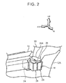
FIG. 2] FIG. 2 is a perspective view showing a state where the sound insulation member according to the first embodiment of the invention is assembled with a front side door. - [
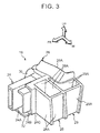
FIG. 3] FIG. 3 is a perspective view showing the sound insulation member according to the first embodiment of the invention. - [
FIG. 4] FIG. 4 is a perspective view of the sound insulation member according to the first embodiment of the invention, as viewed from a different angle. - [
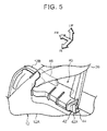
FIG. 5] FIG. 5 is a perspective view showing a state where a sound insulation member according to a second embodiment of the invention is assembled with a front side door. - [
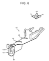
FIG. 6] FIG. 6 is a perspective view showing the sound insulation member according to the second embodiment of the invention. - [
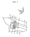
FIG. 7] FIG. 7 is a perspective view showing a state where a sound insulation member according to a third embodiment of the invention is assembled with a rear side door. - [
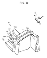
FIG. 8] FIG. 8 is a perspective view showing the sound insulation member according to the third embodiment of the invention. - [
FIG. 9] FIG. 9 is a perspective view showing a state where a sound insulation member according to a fourth embodiment of the invention is assembled with a rear side door. - [
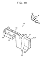
FIG. 10] FIG. 10 is a perspective view showing the sound insulation member according to the fourth embodiment of the invention. - A
sound insulation member 16 and avehicular door structure 10 according to the first embodiment of the invention will be described hereinafter, usingFIGS. 1 to 4 . Incidentally, arrows UP, FR and IN, which are appropriately shown in the drawings, denote an upward direction with respect to a door, a forward direction with respect to the door, and an inward direction with respect to the thickness of the door. Besides, when upward/downward directions, forward/backward directions and inward/outward directions are mentioned in the following description without being otherwise specified, they are meant to indicate the upward/downward directions with respect to a vertical direction of the door, the forward/backward directions with respect to a longitudinal direction of the door, and the inward/outward directions with respect to a thickness direction of the door, respectively. - As shown in
FIG. 1 , thevehicular door structure 10 according to the present embodiment of the invention is mainly equipped with adoor panel 12 of afront side door 11, aninner weather strip 14 that is disposed at an upper portion of thedoor panel 12, asound insulation member 40 that is attached to a door front-side end portion of theinner weather strip 14, and asound insulation member 16 that is attached to a door rear-side end portion of theinner weather strip 14. - Incidentally, it is sufficient that the
sound insulation member 16 or thesound insulation member 40 be attached to at least one of the door front-side end portion and the door rear-side end portion of theinner weather strip 14. For example, thedoor structure 10 may have only thesound insulation member 16 attached to at least one of the end portions of theinner weather strip 14. Besides, in the present embodiment of the invention, thesound insulation member 16 that is attached to the door rear-side end portion of theinner weather strip 14 will be described. Thesound insulation member 40 that is attached to the door front-side end portion of theinner weather strip 14 will be described in the second embodiment of the invention. - The
door panel 12 that constitutes thevehicular door structure 10 is equipped with a metallic doorinner panel 12A that is provided inside in the thickness direction of the door, and a metallic doorouter panel 12B that is provided outside in the thickness direction of the door. Besides, ametallic door frame 20 that is formed in the shape of a frame is provided at an upper portion of the doorinner panel 12A. - It should be noted herein that the
inner weather strip 14 is disposed at the upper portion of the doorinner panel 12A. Besides, an outer weather strip (not shown) is disposed at an upper portion of the doorouter panel 12B. Theinner weather strip 14 is disposed along the doorinner panel 12A on a door belt line from a door front-side end portion of the doorinner panel 12A to a door rear-side end portion of the doorinner panel 12A. More specifically, theinner weather strip 14 is fitted into and assembled with a flange at an upper end portion of the doorinner panel 12A. - As shown in
FIG. 2 , thesound insulation member 16 is attached to the door rear-side end portion of theinner weather strip 14. Thesound insulation member 16 is a resinous blockish part, and is fitted into and assembled with the flange at the upper end portion of the doorinner panel 12A as is the case with theinner weather strip 14. Thesound insulation member 16 is mainly equipped with a fittingportion 24, a sealingportion 26, a dampingportion 28 and a dampingportion 29. Incidentally, in the present embodiment of the invention, for instance, thesound insulation member 16 is formed of a synthetic rubber such as olefinic elastomer (TPO), ethylene-propylene-diene rubber (EPDM) or the like, but the invention is not limited thereto. Thesound insulation member 16 may be formed of other resin materials. The same holds true for the second to fourth embodiments of the invention. - As shown in
FIG. 3 , thefitting portion 24 is provided at a region of thesound insulation member 16 to which theinner weather strip 14 is attached (a region that is located on the door front side). As shown inFIG. 4 , thefitting portion 24 is equipped with aninclined surface 30. The end portion of theinner weather strip 14 is placed against theinclined surface 30 to abut thereon. Besides, a plurality ofprotrusions inclined surface 30. Thefitting portion 24 assumes a convexo-concave shape corresponding to the shape of the end portion of theinner weather strip 14. It should be noted herein that theprotrusion 24A, theprotrusion 24B and theprotrusion 24C are arranged apart from one another in the thickness direction of the door. Theprotrusion 24A, which is located outside in the thickness direction of the door, is formed in the shape of a tube that is open on a tip side thereof. Besides, theprotrusion 24B, which is located at a center in the thickness direction of the door, and theprotrusion 24C, which is located inside in the thickness direction of the door, are formed substantially in the shape of the vertically inverted letter "L". Incidentally, the invention is not limited to this configuration. The shape of thefitting portion 24 may be set in accordance with the shape of the end portion of theinner weather strip 14. The number of protrusions may be changed, and the shape of the protrusions may be changed. - A covering
portion 32 that covers a door lower side of theinner weather strip 14 is formed at thefitting portion 24. The coveringportion 32 is a plate-like region that extends forward with respect to the door from a lower end portion of thefitting portion 24. The coveringportion 32 is configured to enter a gap between the doorinner panel 12A and theinner weather strip 14 when thesound insulation member 16 is attached to theinner weather strip 14. - The sealing
portion 26 is provided at a region that is located behind thefitting portion 24 with respect to the door. The sealingportion 26 is arranged between the door rear-side end portion of theinner weather strip 14 and a lower end portion of thedoor frame 20 when thesound insulation member 16 is attached to theinner weather strip 14. Also, the sealingportion 26 is configured to seal a gap between theinner weather strip 14 and the doorinner panel 12A (seeFIG. 2 ). Besides, a sealinglip 26A is provided at a door rear-side end portion of the sealingportion 26. The sealinglip 26A is elastically deformably formed. As shown inFIG. 2 , the sealinglip 26A is elastically pressed into contact with and seals thedoor frame 20 at an opening edge portion of the doorinner panel 12A. - As shown in
FIG. 3 , the dampingportion 28 and the dampingportion 29 are provided at a region that is located inside the sealingportion 26 in the thickness direction of the door. The dampingportion 28 is formed in the shape of a tube by two pairs of opposedlateral walls 28A and a bottom wall (not shown), and constitutes a space that substantially assumes the shape of a rectangular parallelepiped. Besides, the dampingportion 29 is provided behind the dampingportion 28 with respect to the door. The dampingportion 29 is formed in the shape of a tube by thelateral wall 28A that is common to the dampingportion 28, threelateral walls 29A and a bottom wall (not shown). It should be noted herein that one of thelateral walls 29A constituting the dampingportion 29 is curved along the contour of the sealinglip 26A, and constitutes a space that assumes the shape of a partially inwardly crushed rectangular parallelepiped. - Incidentally, it is sufficient that the damping
portion 28 and the dampingportion 29 be formed in the shape of a tube by lateral walls and a bottom wall. The dampingportion 28 and the dampingportion 29 may be formed in other shapes. For example, the dampingportion 28 and the dampingportion 29 may be formed substantially in the shape of a triangle in a plan view. Besides, although the two damping portions are formed in the present embodiment of the invention, the invention is not limited thereto. Three or more damping portions may be formed. On the contrary, only one damping portion may be formed. - Next, the operation and effect of the
sound insulation member 16 and thevehicular door structure 10 of the present embodiment of the invention will be described. According to thevehicular door structure 10 of the present embodiment of the invention, as shown inFIG. 2 , theinner weather strip 14 and thesound insulation member 16 can be assembled with the doorinner panel 12A with the door rear-side end portion of theinner weather strip 14 and thefitting portion 24 of thesound insulation member 16 fitted to each other. Thus, the assembling man-hour can be reduced in comparison with the case where theinner weather strip 14 and thesound insulation member 16 are assembled with the doorinner panel 12A in separate processes. Incidentally, the invention is not limited to this configuration. Theinner weather strip 14 may be assembled with the doorinner panel 12A with thesound insulation member 16 assembled with the upper end portion of the doorinner panel 12A in advance. - Besides, the gap between the
inner weather strip 14 and the doorinner panel 12A can be filled by the sealingportion 26 that is provided on thesound insulation member 16. Therefore, sound insulating properties can be ensured without filling the gap with a sponge or the like. - Besides, sound insulating properties can be obtained by attaching the
sound insulation member 16 to at least one of the door front-side end portion and the door rear-side end portion of theinner weather strip 14. Therefore, the number of parts can be reduced in comparison with the case where a large number of sound insulation materials are provided on a door glass. Furthermore, the trouble of attaching the sound insulation member to the door glass can be saved, so the cost can be reduced. - Besides, the covering
portion 32, which is provided at the lower end portion of thefitting portion 24, has entered the gap between the doorinner panel 12A and theinner weather strip 14. Therefore, even in the case where a gap is created between theinner weather strip 14 and thefitting portion 24, the coveringportion 32 covers the door lower side of theinner weather strip 14, and sound insulating properties can thereby be ensured. - Besides, the sealing
portion 26 of thesound insulation member 16 of the present embodiment of the invention is provided with the sealinglip 26A. Therefore, even in the case where thesound insulation member 16 is applied to a vehicle with the doorinner panel 12A or thedoor frame 20 that assumes a different shape, the sealing lip is elastically deformed, is pressed into contact with the opening edge portion of the doorinner panel 12A, and seals the gap. Thus, sound insulating properties can be ensured. Besides, the road noise and wind noise that have entered from the gap between theinner weather strip 14 and the doorinner panel 12A can be damped by the dampingportion 28 and the dampingportion 29. - Next, the
sound insulation member 40 according to the second embodiment of the invention will be described, usingFIGS. 5 and6 . As shown inFIG. 5 , thesound insulation member 40 of the present embodiment of the invention is attached to the door front-side end portion of the doorinner panel 12A, and is mainly equipped with afitting portion 42 and a sealingportion 46. Incidentally, for the sake of convenience of explanation, the weather strip is not shown inFIG. 5 . However, the inner weather strip is disposed at the upper portion of the doorinner panel 12A. Thesound insulation member 40 is attached to this inner weather strip. - The
fitting portion 42 is provided at a door rear-side end portion of thesound insulation member 40. As shown inFIG. 6 , thefitting portion 42 is formed in a convexo-concave shape corresponding to the shape of the end portion of the inner weather strip. Besides, thefitting portion 42 is provided with aprotrusion 42A, and is configured such that thisprotrusion 42A enters the inner weather strip to be fitted thereto. Besides, a plate-like covering portion 44 extends backward with respect to the door from a lower end portion of thefitting portion 42. The coveringportion 44 is configured to enter a gap between the doorinner panel 12A and the inner weather strip when thesound insulation member 40 is attached to the inner weather strip. - The sealing
portion 46 is provided at a region on the opposite side of thefitting portion 42. The sealingportion 46 is arranged between the door front-side end portion of the inner weather strip and the lower end portion of thedoor frame 20 when thesound insulation member 40 is attached to the inner weather strip. Also, the sealingportion 46 is configured to seal the gap between the inner weather strip and the doorinner panel 12A. Besides, tworeinforcement ribs 48 that reinforce thesound insulation member 40 are provided between thefitting portion 42 and the sealingportion 46. - According to the
sound insulation member 40 of the present embodiment of the invention, an operation and an effect that are similar to those of thesound insulation member 16 of the first embodiment of the invention are achieved. In particular, as shown inFIG. 1 , thesound insulation member 40 is attached to the door front side of theinner weather strip 14, and thesound insulation member 16 is attached to the door rear-side end portion of theinner weather strip 14. Sound insulating properties can thereby be enhanced in comparison with the case where the sound insulation member is attached to only one of the end portions of theweather strip 14. Incidentally, thesound insulation member 40 of the present embodiment of the invention is not equipped with the dampingportion 28 as in the case of thesound insulation member 16 of the first embodiment of the invention. However, thesound insulation member 40 may be provided with a damping portion in order to obtain a damping effect. - Next, a
sound insulation member 60 according to the third embodiment of the invention will be described, usingFIGS. 7 and8 . Incidentally, in the following third and fourth embodiments of the invention, a sound insulation member that is attached to a weather strip on a rear side door side will be described. - As shown in
FIG. 7 , aninner weather strip 64 is disposed at an upper portion of a doorinner panel 62 of a rear side door. The resinous blockishsound insulation member 60 is attached to a door front-side end portion of thisinner weather strip 64. Thesound insulation member 60 is mainly equipped with afitting portion 68, a sealingportion 70, a dampingportion 72 and a dampingportion 74. A door front-side end portion of thesound insulation member 60 abuts on arear door frame 66. - As shown in
FIG. 8 , thefitting portion 68 is formed in a convexo-concave shape by a plurality ofprotrusions 68A, and is configured to be fitted to the end portion of theinner weather strip 64. Besides, a plate-like covering portion 76 that extends forward with respect to the door is provided at a lower end portion of thefitting portion 68. Also, the coveringportion 76 is configured to enter a gap between the doorinner panel 62 and theinner weather strip 64 when thesound insulation member 60 is attached to theinner weather strip 64. - The sealing
portion 70 is provided at a region on the opposite side of thefitting portion 68. The sealingportion 70 is arranged between the door front-side end portion of theinner weather strip 64 and therear door frame 66 when thesound insulation member 60 is attached to the weather strip. Also, the sealingportion 70 is configured to seal the gap between theinner weather strip 64 and the doorinner panel 62. Besides, the sealingportion 70 is provided with an elasticallydeformable sealing lip 70A. This sealinglip 70A is in contact with therear door frame 66 to seal thesound insulation member 60 and therear door frame 66. - As shown in
FIG. 7 , the dampingportion 72 and the dampingportion 74 are provided inside thefitting portion 68 in the thickness direction of the door. The dampingportion 72 and the dampingportion 74 constitute a space that substantially assumes the shape of a rectangular parallelepiped, as is the case with the dampingportion 28 of the first embodiment of the invention. - According to the
sound insulation member 60 of the present embodiment of the invention, an operation and an effect that are similar to those of thesound insulation member 16 of the first embodiment of the invention are achieved. - Next, a
sound insulation member 80 according to the fourth embodiment of the invention will be described, usingFIGS. 9 and10 . As shown inFIG. 9 , theinner weather strip 64 is disposed at the upper portion of the doorinner panel 62 of the rear side door. The resinous blockishsound insulation member 80 is attached to a door-side end portion of thisinner weather strip 64. Thesound insulation member 80 is mainly equipped with afitting portion 82, a sealingportion 84, a dampingportion 88 and a dampingportion 90. A door rear-side end portion of thesound insulation member 80 abuts on adivision bar 100. - As shown in
FIG. 10 , thefitting portion 82 is formed in a convexo-concave shape by aprotrusion 82A, and is configured to be fitted to the end portion of theinner weather strip 64. Besides, a plate-like covering portion 86 that extends forward with respect to the door is provided at a lower end portion of thefitting portion 82. Also, the coveringportion 86 is configured to enter the gap between the doorinner panel 62 and theinner weather strip 64 when thesound insulation member 80 is attached to theinner weather strip 64. - The sealing
portion 84 is provided at a region that is located behind thefitting portion 82 with respect to the door. The sealingportion 84 is configured to seal the gap between theinner weather strip 64 and the doorinner panel 62. Besides, the dampingportion 88 and the dampingportion 90 are provided outside the sealingportion 84 in the thickness direction of the door. The dampingportion 88 and the dampingportion 90 constitute a space that substantially assumes the shape of a rectangular parallelepiped, as is the case with the dampingportion 28 of the first embodiment of the invention. - According to the
sound insulation member 80 of the present embodiment of the invention, an operation and an effect that are similar to those of thesound insulation member 16 of the first embodiment of the invention are achieved. Incidentally, by attaching thesound insulation member 16 of the first embodiment of the invention and thesound insulation member 40 of the second embodiment of the invention to theinner weather strip 14 on the front side door side, and attaching thesound insulation member 60 of the third embodiment of the invention and thesound insulation member 80 of the present embodiment of the invention to theinner weather strip 64 on an outside door side, sound insulating properties can be enhanced to the maximum in comparison with the cases where only one, two or three of the sound insulation members are attached to the inner weather strip(s). - While the sound insulation members according to the first to fourth embodiments of the invention have been described above, it is obvious that the first to fourth embodiments of the invention may be appropriately combined with one another to be used, and can be carried out in various modes within such a range as not to depart from the gist of the invention.
- The disclosure of
Japanese Patent Application No. 2013-246610 filed on November 28, 2013 - All the documents, patent applications and technical standards mentioned in the present specification are incorporated in the present specification by reference to the same extent as in the case where incorporation of each of the documents, the patent applications and the technical standards by reference is concretely and individually mentioned.
Claims (5)
- A sound insulation member comprising:a fitting portion that is fitted into at least one of a door front-side end portion and a door rear-side end portion of an inner weather strip that is disposed at an upper portion of a door inner panel; anda sealing portion that fills a gap between the inner weather strip and the door inner panel.
- The sound insulation member according to claim 1, wherein
the fitting portion is provided with a covering portion that covers a door lower side of the inner weather strip. - The sound insulation member according to claim 1 or 2, wherein
the sealing portion is equipped with a sealing lip that is elastically pressed into contact with an opening edge portion of the door inner panel. - The sound insulation member according to any one of claims 1 to 3, further comprising:a tubular damping portion that is surrounded by lateral walls and a bottom wall.
- A vehicular door structure comprising:a door inner panel of a vehicle;an inner weather strip that is disposed at an upper portion of the door inner panel; andthe sound insulation member according to any one of claims 1 to 4 that is fitted to a door front-side end portion or a door rear-side end portion of the inner weather strip.
Applications Claiming Priority (2)
| Application Number | Priority Date | Filing Date | Title |
|---|---|---|---|
| JP2013246610A JP5848313B2 (en) | 2013-11-28 | 2013-11-28 | Sound insulation member and vehicle door structure |
| PCT/JP2014/079372 WO2015079878A1 (en) | 2013-11-28 | 2014-11-05 | Sound insulation member, and vehicular door structure |
Publications (3)
| Publication Number | Publication Date |
|---|---|
| EP3090892A1 true EP3090892A1 (en) | 2016-11-09 |
| EP3090892A4 EP3090892A4 (en) | 2016-11-23 |
| EP3090892B1 EP3090892B1 (en) | 2020-12-23 |
Family
ID=53198826
Family Applications (1)
| Application Number | Title | Priority Date | Filing Date |
|---|---|---|---|
| EP14865629.1A Active EP3090892B1 (en) | 2013-11-28 | 2014-11-05 | Sound insulation member, and vehicular door structure |
Country Status (5)
| Country | Link |
|---|---|
| US (1) | US10035411B2 (en) |
| EP (1) | EP3090892B1 (en) |
| JP (1) | JP5848313B2 (en) |
| CN (1) | CN105934356B (en) |
| WO (1) | WO2015079878A1 (en) |
Families Citing this family (12)
| Publication number | Priority date | Publication date | Assignee | Title |
|---|---|---|---|---|
| JP6698368B2 (en) * | 2016-02-04 | 2020-05-27 | 西川ゴム工業株式会社 | Automotive door seal structure |
| JP6715016B2 (en) * | 2016-02-04 | 2020-07-01 | 西川ゴム工業株式会社 | Automotive door seal structure |
| US10434857B2 (en) * | 2016-08-19 | 2019-10-08 | Ford Global Technologies, Llc | Vehicle window weatherstripping having an inner belt with interlocking end details |
| JP6319398B2 (en) * | 2016-10-28 | 2018-05-09 | マツダ株式会社 | Vehicle side body structure and manufacturing method thereof |
| US12404716B2 (en) * | 2018-04-09 | 2025-09-02 | ASSA ABLOY Accessories and Door Controls Group, Inc. | Integrated guide system and door seal for a soft close sliding door |
| FR3111299B1 (en) * | 2020-06-16 | 2022-11-25 | Psa Automobiles Sa | MOTOR VEHICLE DOOR TRIM |
| JP7406515B2 (en) * | 2021-02-04 | 2023-12-27 | 東海興業株式会社 | Belt molding and its manufacturing method |
| JP7691672B2 (en) * | 2021-03-11 | 2025-06-12 | トヨタ自動車九州株式会社 | Sound insulation materials |
| JP7605728B2 (en) | 2021-12-21 | 2024-12-24 | 東海興業株式会社 | Belt molding manufacturing method |
| KR20240086262A (en) * | 2022-12-09 | 2024-06-18 | 현대자동차주식회사 | Inner belt mounting structure for door of vehicle |
| US12403754B2 (en) * | 2023-04-18 | 2025-09-02 | Rivian Ip Holdings, Llc | Hidden outer belt seal |
| US12454169B2 (en) * | 2023-09-22 | 2025-10-28 | Nissan North America, Inc. | Vehicle sealing assembly |
Family Cites Families (38)
| Publication number | Priority date | Publication date | Assignee | Title |
|---|---|---|---|---|
| US3742649A (en) * | 1970-04-14 | 1973-07-03 | Draftex Gmbh | Support for decorative moldings on door or window frames provided with rubber or plastic sealstrips |
| JPS53153624U (en) * | 1977-05-10 | 1978-12-02 | ||
| US4817336A (en) * | 1987-05-30 | 1989-04-04 | Toyoda Gosei Co., Ltd. | Glass run connecting corner piece |
| US4894954A (en) * | 1987-12-24 | 1990-01-23 | Toyoda Gosei Co., Ltd. | Weather strip for vehicle |
| JPH0269529U (en) * | 1988-11-16 | 1990-05-25 | ||
| US4956941A (en) * | 1989-01-12 | 1990-09-18 | The Standard Products Company | Front loading flush glass run system |
| US5636895A (en) * | 1992-10-27 | 1997-06-10 | Toyoda Gosei Co., Ltd. | Seal structure for weather strip |
| US5353549A (en) * | 1992-11-06 | 1994-10-11 | The Standard Products Company | Molded weatherstrip and method |
| JPH0825976A (en) * | 1994-07-14 | 1996-01-30 | Suzuki Motor Corp | Structure of door glass run |
| US5524388A (en) * | 1995-06-09 | 1996-06-11 | Ford Motor Company | Automotive window stability assembly |
| US5815985A (en) * | 1996-07-09 | 1998-10-06 | Illinois Tool Works Inc. | Stabilizer for automobile door glass |
| JP3633332B2 (en) | 1999-01-12 | 2005-03-30 | 豊田合成株式会社 | Weather strip for fixed window |
| US6502832B2 (en) * | 2000-01-27 | 2003-01-07 | Toyoda Gosei Co., Ltd. | Automotive seal component for vehicle door |
| JP2001219738A (en) | 2000-02-14 | 2001-08-14 | Nishikawa Rubber Co Ltd | Sound insulation structure of belt line section of automobile |
| JP2001260661A (en) * | 2000-03-23 | 2001-09-26 | Toyoda Gosei Co Ltd | Mounting structure for glass inner weather strip of automobile door |
| JP2003200737A (en) | 2002-01-08 | 2003-07-15 | Nishikawa Rubber Co Ltd | Weatherstrip for automobile |
| JP3706347B2 (en) * | 2002-03-04 | 2005-10-12 | 西川ゴム工業株式会社 | Automotive door structure |
| KR100471843B1 (en) * | 2002-06-11 | 2005-03-08 | 현대자동차주식회사 | Mounting structure of out side weather strip in automobile |
| JP2004224198A (en) | 2003-01-23 | 2004-08-12 | Nishikawa Rubber Co Ltd | Weather Strip |
| JP2005297794A (en) * | 2004-04-13 | 2005-10-27 | Toyota Motor Corp | Door belt line seal structure |
| US7484287B2 (en) * | 2004-09-10 | 2009-02-03 | Tokai Kogyo Company Limited | Apparatus for assembling flexible molding main body part and cover part as molding |
| GB2421044A (en) * | 2004-12-09 | 2006-06-14 | Gdx North America Inc | Sealing arrangement including sections |
| JP4248530B2 (en) * | 2005-06-27 | 2009-04-02 | トヨタ自動車株式会社 | Seal structure |
| JP4235655B2 (en) * | 2006-04-27 | 2009-03-11 | アイシン精機株式会社 | Belt Mall |
| US8001727B2 (en) * | 2007-07-24 | 2011-08-23 | Magna International Inc | Sealing molding with insert for forming closeout surface |
| JP2009126313A (en) * | 2007-11-22 | 2009-06-11 | Aisin Seiki Co Ltd | Vehicle mall |
| JP5483418B2 (en) * | 2009-12-01 | 2014-05-07 | 西川ゴム工業株式会社 | Lower seal |
| JP5805942B2 (en) * | 2010-12-06 | 2015-11-10 | シロキ工業株式会社 | Belt molding for vehicle doors |
| JP5710999B2 (en) * | 2011-02-14 | 2015-04-30 | シロキ工業株式会社 | the mall |
| CN103635338A (en) * | 2011-06-23 | 2014-03-12 | 丰田自动车株式会社 | Door structure for vehicle |
| US8572897B2 (en) * | 2011-09-14 | 2013-11-05 | Ford Global Technologies, Llc | Weatherstrip cinch clip |
| CN103373207B (en) * | 2012-04-27 | 2016-12-07 | 西川橡胶工业股份有限公司 | The sealing structure of automobile door |
| CN103568797B (en) * | 2012-08-01 | 2017-04-12 | 亨尼格斯汽车密封系统北美公司 | Dual end cap for seal assembly |
| US9211781B2 (en) * | 2012-08-31 | 2015-12-15 | Honda Motor Co., Ltd. | Vehicle door |
| JP5968750B2 (en) * | 2012-10-05 | 2016-08-10 | 西川ゴム工業株式会社 | Glass run and belt line weatherstrip connection structure |
| JP5626310B2 (en) * | 2012-10-23 | 2014-11-19 | トヨタ自動車株式会社 | Vehicle door structure |
| US9248729B2 (en) * | 2013-12-19 | 2016-02-02 | Nissan North America, Inc. | Vehicle door structure |
| JP6140767B2 (en) * | 2015-06-05 | 2017-05-31 | トヨタ自動車東日本株式会社 | Transmission sound shielding member and transmission sound shielding structure using the same |
-
2013
- 2013-11-28 JP JP2013246610A patent/JP5848313B2/en active Active
-
2014
- 2014-11-05 WO PCT/JP2014/079372 patent/WO2015079878A1/en not_active Ceased
- 2014-11-05 CN CN201480064796.5A patent/CN105934356B/en active Active
- 2014-11-05 US US15/100,118 patent/US10035411B2/en active Active
- 2014-11-05 EP EP14865629.1A patent/EP3090892B1/en active Active
Also Published As
| Publication number | Publication date |
|---|---|
| US10035411B2 (en) | 2018-07-31 |
| WO2015079878A1 (en) | 2015-06-04 |
| JP2015104952A (en) | 2015-06-08 |
| CN105934356B (en) | 2018-03-27 |
| EP3090892A4 (en) | 2016-11-23 |
| EP3090892B1 (en) | 2020-12-23 |
| JP5848313B2 (en) | 2016-01-27 |
| CN105934356A (en) | 2016-09-07 |
| US20170057334A1 (en) | 2017-03-02 |
Similar Documents
| Publication | Publication Date | Title |
|---|---|---|
| US10035411B2 (en) | Sound insulation member and vehicular door structure | |
| US8151521B2 (en) | Vehicle door structure | |
| US8985678B2 (en) | Body front structure for automobile | |
| US9162625B2 (en) | Structure for vehicle body lateral section | |
| CN205706114U (en) | Filler rod installation constitution | |
| JP6585952B2 (en) | Mounting structure for automobile door molding | |
| US10286768B2 (en) | Inner weather strip and seal structure of vehicle door | |
| JP6700979B2 (en) | Glass run for car door | |
| JP6500232B2 (en) | Holding structure for automotive glass run | |
| CN107627823B (en) | Glass run channel | |
| JP6833480B2 (en) | Mounting structure of glass run for car doors | |
| JP2020179842A (en) | Seal component for vehicle door window | |
| CN107585005B (en) | Attachment structure of top-side weather strip | |
| JP2009006851A (en) | Door weather strip | |
| US6932422B2 (en) | Attachment structure of weather strip for motor vehicle | |
| RU2719069C2 (en) | Compactor for car door, car door, comprising two interconnected sealants, and vehicle | |
| JP6487345B2 (en) | Vehicle door structure | |
| US20250269908A1 (en) | Vehicle rear structure | |
| JP4962859B2 (en) | Glass run | |
| JP6032434B2 (en) | Weather strip | |
| US20250001843A1 (en) | Motor Vehicle With a Side Door | |
| JP2020050226A (en) | Door weather strip | |
| JP2010023650A (en) | Vehicular door structure | |
| JP6652819B2 (en) | Grass run | |
| JP2013129230A (en) | Clip |
Legal Events
| Date | Code | Title | Description |
|---|---|---|---|
| PUAI | Public reference made under article 153(3) epc to a published international application that has entered the european phase |
Free format text: ORIGINAL CODE: 0009012 |
|
| REG | Reference to a national code |
Ref country code: DE Ref legal event code: R079 Ref document number: 602014073679 Country of ref document: DE Free format text: PREVIOUS MAIN CLASS: B60J0005000000 Ipc: B60J0005040000 |
|
| 17P | Request for examination filed |
Effective date: 20160527 |
|
| AK | Designated contracting states |
Kind code of ref document: A1 Designated state(s): AL AT BE BG CH CY CZ DE DK EE ES FI FR GB GR HR HU IE IS IT LI LT LU LV MC MK MT NL NO PL PT RO RS SE SI SK SM TR |
|
| AX | Request for extension of the european patent |
Extension state: BA ME |
|
| A4 | Supplementary search report drawn up and despatched |
Effective date: 20161026 |
|
| RIC1 | Information provided on ipc code assigned before grant |
Ipc: B60J 10/00 20160101ALI20161020BHEP Ipc: B60J 5/04 20060101AFI20161020BHEP Ipc: B60J 10/40 20160101ALI20161020BHEP Ipc: B60J 10/75 20160101ALI20161020BHEP Ipc: B60J 10/50 20160101ALI20161020BHEP |
|
| DAX | Request for extension of the european patent (deleted) | ||
| STAA | Information on the status of an ep patent application or granted ep patent |
Free format text: STATUS: EXAMINATION IS IN PROGRESS |
|
| 17Q | First examination report despatched |
Effective date: 20190829 |
|
| GRAP | Despatch of communication of intention to grant a patent |
Free format text: ORIGINAL CODE: EPIDOSNIGR1 |
|
| STAA | Information on the status of an ep patent application or granted ep patent |
Free format text: STATUS: GRANT OF PATENT IS INTENDED |
|
| INTG | Intention to grant announced |
Effective date: 20200713 |
|
| GRAS | Grant fee paid |
Free format text: ORIGINAL CODE: EPIDOSNIGR3 |
|
| GRAA | (expected) grant |
Free format text: ORIGINAL CODE: 0009210 |
|
| STAA | Information on the status of an ep patent application or granted ep patent |
Free format text: STATUS: THE PATENT HAS BEEN GRANTED |
|
| RIN1 | Information on inventor provided before grant (corrected) |
Inventor name: KAWAKAMI, YASUAKI Inventor name: TOYOTA, MASARU Inventor name: SUZUKI, KOUJI Inventor name: OOTSUKA, SUSUMU Inventor name: INAYOSHI, YUICHIRO |
|
| RAP1 | Party data changed (applicant data changed or rights of an application transferred) |
Owner name: TOYOTA JIDOSHA KABUSHIKI KAISHA Owner name: NIFCO INC. Owner name: VTEC CO., LTD. |
|
| AK | Designated contracting states |
Kind code of ref document: B1 Designated state(s): AL AT BE BG CH CY CZ DE DK EE ES FI FR GB GR HR HU IE IS IT LI LT LU LV MC MK MT NL NO PL PT RO RS SE SI SK SM TR |
|
| REG | Reference to a national code |
Ref country code: GB Ref legal event code: FG4D |
|
| RIN1 | Information on inventor provided before grant (corrected) |
Inventor name: SUZUKI, KOUJI Inventor name: OOTSUKA, SUSUMU Inventor name: TOYOTA, MASARU Inventor name: KAWAKAMI, YASUAKI Inventor name: INAYOSHI, YUICHIRO |
|
| REG | Reference to a national code |
Ref country code: DE Ref legal event code: R096 Ref document number: 602014073679 Country of ref document: DE |
|
| REG | Reference to a national code |
Ref country code: AT Ref legal event code: REF Ref document number: 1347379 Country of ref document: AT Kind code of ref document: T Effective date: 20210115 |
|
| REG | Reference to a national code |
Ref country code: IE Ref legal event code: FG4D |
|
| PG25 | Lapsed in a contracting state [announced via postgrant information from national office to epo] |
Ref country code: GR Free format text: LAPSE BECAUSE OF FAILURE TO SUBMIT A TRANSLATION OF THE DESCRIPTION OR TO PAY THE FEE WITHIN THE PRESCRIBED TIME-LIMIT Effective date: 20210324 Ref country code: RS Free format text: LAPSE BECAUSE OF FAILURE TO SUBMIT A TRANSLATION OF THE DESCRIPTION OR TO PAY THE FEE WITHIN THE PRESCRIBED TIME-LIMIT Effective date: 20201223 Ref country code: FI Free format text: LAPSE BECAUSE OF FAILURE TO SUBMIT A TRANSLATION OF THE DESCRIPTION OR TO PAY THE FEE WITHIN THE PRESCRIBED TIME-LIMIT Effective date: 20201223 Ref country code: NO Free format text: LAPSE BECAUSE OF FAILURE TO SUBMIT A TRANSLATION OF THE DESCRIPTION OR TO PAY THE FEE WITHIN THE PRESCRIBED TIME-LIMIT Effective date: 20210323 |
|
| REG | Reference to a national code |
Ref country code: AT Ref legal event code: MK05 Ref document number: 1347379 Country of ref document: AT Kind code of ref document: T Effective date: 20201223 |
|
| REG | Reference to a national code |
Ref country code: NL Ref legal event code: MP Effective date: 20201223 |
|
| PG25 | Lapsed in a contracting state [announced via postgrant information from national office to epo] |
Ref country code: SE Free format text: LAPSE BECAUSE OF FAILURE TO SUBMIT A TRANSLATION OF THE DESCRIPTION OR TO PAY THE FEE WITHIN THE PRESCRIBED TIME-LIMIT Effective date: 20201223 Ref country code: LV Free format text: LAPSE BECAUSE OF FAILURE TO SUBMIT A TRANSLATION OF THE DESCRIPTION OR TO PAY THE FEE WITHIN THE PRESCRIBED TIME-LIMIT Effective date: 20201223 Ref country code: BG Free format text: LAPSE BECAUSE OF FAILURE TO SUBMIT A TRANSLATION OF THE DESCRIPTION OR TO PAY THE FEE WITHIN THE PRESCRIBED TIME-LIMIT Effective date: 20210323 |
|
| PG25 | Lapsed in a contracting state [announced via postgrant information from national office to epo] |
Ref country code: NL Free format text: LAPSE BECAUSE OF FAILURE TO SUBMIT A TRANSLATION OF THE DESCRIPTION OR TO PAY THE FEE WITHIN THE PRESCRIBED TIME-LIMIT Effective date: 20201223 Ref country code: HR Free format text: LAPSE BECAUSE OF FAILURE TO SUBMIT A TRANSLATION OF THE DESCRIPTION OR TO PAY THE FEE WITHIN THE PRESCRIBED TIME-LIMIT Effective date: 20201223 |
|
| REG | Reference to a national code |
Ref country code: LT Ref legal event code: MG9D |
|
| PG25 | Lapsed in a contracting state [announced via postgrant information from national office to epo] |
Ref country code: SM Free format text: LAPSE BECAUSE OF FAILURE TO SUBMIT A TRANSLATION OF THE DESCRIPTION OR TO PAY THE FEE WITHIN THE PRESCRIBED TIME-LIMIT Effective date: 20201223 Ref country code: EE Free format text: LAPSE BECAUSE OF FAILURE TO SUBMIT A TRANSLATION OF THE DESCRIPTION OR TO PAY THE FEE WITHIN THE PRESCRIBED TIME-LIMIT Effective date: 20201223 Ref country code: SK Free format text: LAPSE BECAUSE OF FAILURE TO SUBMIT A TRANSLATION OF THE DESCRIPTION OR TO PAY THE FEE WITHIN THE PRESCRIBED TIME-LIMIT Effective date: 20201223 Ref country code: RO Free format text: LAPSE BECAUSE OF FAILURE TO SUBMIT A TRANSLATION OF THE DESCRIPTION OR TO PAY THE FEE WITHIN THE PRESCRIBED TIME-LIMIT Effective date: 20201223 Ref country code: PT Free format text: LAPSE BECAUSE OF FAILURE TO SUBMIT A TRANSLATION OF THE DESCRIPTION OR TO PAY THE FEE WITHIN THE PRESCRIBED TIME-LIMIT Effective date: 20210423 Ref country code: LT Free format text: LAPSE BECAUSE OF FAILURE TO SUBMIT A TRANSLATION OF THE DESCRIPTION OR TO PAY THE FEE WITHIN THE PRESCRIBED TIME-LIMIT Effective date: 20201223 |
|
| PG25 | Lapsed in a contracting state [announced via postgrant information from national office to epo] |
Ref country code: PL Free format text: LAPSE BECAUSE OF FAILURE TO SUBMIT A TRANSLATION OF THE DESCRIPTION OR TO PAY THE FEE WITHIN THE PRESCRIBED TIME-LIMIT Effective date: 20201223 Ref country code: AT Free format text: LAPSE BECAUSE OF FAILURE TO SUBMIT A TRANSLATION OF THE DESCRIPTION OR TO PAY THE FEE WITHIN THE PRESCRIBED TIME-LIMIT Effective date: 20201223 |
|
| REG | Reference to a national code |
Ref country code: DE Ref legal event code: R097 Ref document number: 602014073679 Country of ref document: DE |
|
| PG25 | Lapsed in a contracting state [announced via postgrant information from national office to epo] |
Ref country code: IS Free format text: LAPSE BECAUSE OF FAILURE TO SUBMIT A TRANSLATION OF THE DESCRIPTION OR TO PAY THE FEE WITHIN THE PRESCRIBED TIME-LIMIT Effective date: 20210423 |
|
| PG25 | Lapsed in a contracting state [announced via postgrant information from national office to epo] |
Ref country code: AL Free format text: LAPSE BECAUSE OF FAILURE TO SUBMIT A TRANSLATION OF THE DESCRIPTION OR TO PAY THE FEE WITHIN THE PRESCRIBED TIME-LIMIT Effective date: 20201223 Ref country code: IT Free format text: LAPSE BECAUSE OF FAILURE TO SUBMIT A TRANSLATION OF THE DESCRIPTION OR TO PAY THE FEE WITHIN THE PRESCRIBED TIME-LIMIT Effective date: 20201223 |
|
| PLBE | No opposition filed within time limit |
Free format text: ORIGINAL CODE: 0009261 |
|
| STAA | Information on the status of an ep patent application or granted ep patent |
Free format text: STATUS: NO OPPOSITION FILED WITHIN TIME LIMIT |
|
| PG25 | Lapsed in a contracting state [announced via postgrant information from national office to epo] |
Ref country code: DK Free format text: LAPSE BECAUSE OF FAILURE TO SUBMIT A TRANSLATION OF THE DESCRIPTION OR TO PAY THE FEE WITHIN THE PRESCRIBED TIME-LIMIT Effective date: 20201223 Ref country code: ES Free format text: LAPSE BECAUSE OF FAILURE TO SUBMIT A TRANSLATION OF THE DESCRIPTION OR TO PAY THE FEE WITHIN THE PRESCRIBED TIME-LIMIT Effective date: 20201223 |
|
| PGFP | Annual fee paid to national office [announced via postgrant information from national office to epo] |
Ref country code: GB Payment date: 20210930 Year of fee payment: 8 |
|
| 26N | No opposition filed |
Effective date: 20210924 |
|
| PGFP | Annual fee paid to national office [announced via postgrant information from national office to epo] |
Ref country code: CZ Payment date: 20211015 Year of fee payment: 8 Ref country code: TR Payment date: 20211103 Year of fee payment: 8 |
|
| PG25 | Lapsed in a contracting state [announced via postgrant information from national office to epo] |
Ref country code: SI Free format text: LAPSE BECAUSE OF FAILURE TO SUBMIT A TRANSLATION OF THE DESCRIPTION OR TO PAY THE FEE WITHIN THE PRESCRIBED TIME-LIMIT Effective date: 20201223 |
|
| PGFP | Annual fee paid to national office [announced via postgrant information from national office to epo] |
Ref country code: FR Payment date: 20211018 Year of fee payment: 8 |
|
| PG25 | Lapsed in a contracting state [announced via postgrant information from national office to epo] |
Ref country code: IS Free format text: LAPSE BECAUSE OF FAILURE TO SUBMIT A TRANSLATION OF THE DESCRIPTION OR TO PAY THE FEE WITHIN THE PRESCRIBED TIME-LIMIT Effective date: 20210423 |
|
| PG25 | Lapsed in a contracting state [announced via postgrant information from national office to epo] |
Ref country code: MC Free format text: LAPSE BECAUSE OF FAILURE TO SUBMIT A TRANSLATION OF THE DESCRIPTION OR TO PAY THE FEE WITHIN THE PRESCRIBED TIME-LIMIT Effective date: 20201223 |
|
| REG | Reference to a national code |
Ref country code: CH Ref legal event code: PL |
|
| PG25 | Lapsed in a contracting state [announced via postgrant information from national office to epo] |
Ref country code: LU Free format text: LAPSE BECAUSE OF NON-PAYMENT OF DUE FEES Effective date: 20211105 Ref country code: BE Free format text: LAPSE BECAUSE OF NON-PAYMENT OF DUE FEES Effective date: 20211130 |
|
| REG | Reference to a national code |
Ref country code: BE Ref legal event code: MM Effective date: 20211130 |
|
| PG25 | Lapsed in a contracting state [announced via postgrant information from national office to epo] |
Ref country code: LI Free format text: LAPSE BECAUSE OF NON-PAYMENT OF DUE FEES Effective date: 20211130 Ref country code: CH Free format text: LAPSE BECAUSE OF NON-PAYMENT OF DUE FEES Effective date: 20211130 |
|
| PG25 | Lapsed in a contracting state [announced via postgrant information from national office to epo] |
Ref country code: IE Free format text: LAPSE BECAUSE OF NON-PAYMENT OF DUE FEES Effective date: 20211105 |
|
| PG25 | Lapsed in a contracting state [announced via postgrant information from national office to epo] |
Ref country code: HU Free format text: LAPSE BECAUSE OF FAILURE TO SUBMIT A TRANSLATION OF THE DESCRIPTION OR TO PAY THE FEE WITHIN THE PRESCRIBED TIME-LIMIT; INVALID AB INITIO Effective date: 20141105 |
|
| PG25 | Lapsed in a contracting state [announced via postgrant information from national office to epo] |
Ref country code: CY Free format text: LAPSE BECAUSE OF FAILURE TO SUBMIT A TRANSLATION OF THE DESCRIPTION OR TO PAY THE FEE WITHIN THE PRESCRIBED TIME-LIMIT Effective date: 20201223 |
|
| GBPC | Gb: european patent ceased through non-payment of renewal fee |
Effective date: 20221105 |
|
| PG25 | Lapsed in a contracting state [announced via postgrant information from national office to epo] |
Ref country code: CZ Free format text: LAPSE BECAUSE OF NON-PAYMENT OF DUE FEES Effective date: 20221105 |
|
| PG25 | Lapsed in a contracting state [announced via postgrant information from national office to epo] |
Ref country code: GB Free format text: LAPSE BECAUSE OF NON-PAYMENT OF DUE FEES Effective date: 20221105 |
|
| PG25 | Lapsed in a contracting state [announced via postgrant information from national office to epo] |
Ref country code: FR Free format text: LAPSE BECAUSE OF NON-PAYMENT OF DUE FEES Effective date: 20221130 |
|
| PG25 | Lapsed in a contracting state [announced via postgrant information from national office to epo] |
Ref country code: MK Free format text: LAPSE BECAUSE OF FAILURE TO SUBMIT A TRANSLATION OF THE DESCRIPTION OR TO PAY THE FEE WITHIN THE PRESCRIBED TIME-LIMIT Effective date: 20201223 |
|
| PG25 | Lapsed in a contracting state [announced via postgrant information from national office to epo] |
Ref country code: MT Free format text: LAPSE BECAUSE OF FAILURE TO SUBMIT A TRANSLATION OF THE DESCRIPTION OR TO PAY THE FEE WITHIN THE PRESCRIBED TIME-LIMIT Effective date: 20201223 |
|
| PGFP | Annual fee paid to national office [announced via postgrant information from national office to epo] |
Ref country code: DE Payment date: 20250930 Year of fee payment: 12 |