EP3090484B1 - Imitationssolarmodul zur verwendung in einer versetzten oder unregelmässig geformten solarzellengruppe - Google Patents
Imitationssolarmodul zur verwendung in einer versetzten oder unregelmässig geformten solarzellengruppe Download PDFInfo
- Publication number
- EP3090484B1 EP3090484B1 EP15779940.4A EP15779940A EP3090484B1 EP 3090484 B1 EP3090484 B1 EP 3090484B1 EP 15779940 A EP15779940 A EP 15779940A EP 3090484 B1 EP3090484 B1 EP 3090484B1
- Authority
- EP
- European Patent Office
- Prior art keywords
- body portion
- module
- imitation
- modules
- solar module
- Prior art date
- Legal status (The legal status is an assumption and is not a legal conclusion. Google has not performed a legal analysis and makes no representation as to the accuracy of the status listed.)
- Active
Links
Images






Classifications
-
- H—ELECTRICITY
- H02—GENERATION; CONVERSION OR DISTRIBUTION OF ELECTRIC POWER
- H02S—GENERATION OF ELECTRIC POWER BY CONVERSION OF INFRARED RADIATION, VISIBLE LIGHT OR ULTRAVIOLET LIGHT, e.g. USING PHOTOVOLTAIC [PV] MODULES
- H02S30/00—Structural details of PV modules other than those related to light conversion
-
- H—ELECTRICITY
- H02—GENERATION; CONVERSION OR DISTRIBUTION OF ELECTRIC POWER
- H02S—GENERATION OF ELECTRIC POWER BY CONVERSION OF INFRARED RADIATION, VISIBLE LIGHT OR ULTRAVIOLET LIGHT, e.g. USING PHOTOVOLTAIC [PV] MODULES
- H02S20/00—Supporting structures for PV modules
- H02S20/20—Supporting structures directly fixed to an immovable object
- H02S20/22—Supporting structures directly fixed to an immovable object specially adapted for buildings
- H02S20/23—Supporting structures directly fixed to an immovable object specially adapted for buildings specially adapted for roof structures
-
- H—ELECTRICITY
- H02—GENERATION; CONVERSION OR DISTRIBUTION OF ELECTRIC POWER
- H02S—GENERATION OF ELECTRIC POWER BY CONVERSION OF INFRARED RADIATION, VISIBLE LIGHT OR ULTRAVIOLET LIGHT, e.g. USING PHOTOVOLTAIC [PV] MODULES
- H02S20/00—Supporting structures for PV modules
- H02S20/20—Supporting structures directly fixed to an immovable object
- H02S20/22—Supporting structures directly fixed to an immovable object specially adapted for buildings
- H02S20/23—Supporting structures directly fixed to an immovable object specially adapted for buildings specially adapted for roof structures
- H02S20/25—Roof tile elements
-
- H—ELECTRICITY
- H02—GENERATION; CONVERSION OR DISTRIBUTION OF ELECTRIC POWER
- H02S—GENERATION OF ELECTRIC POWER BY CONVERSION OF INFRARED RADIATION, VISIBLE LIGHT OR ULTRAVIOLET LIGHT, e.g. USING PHOTOVOLTAIC [PV] MODULES
- H02S30/00—Structural details of PV modules other than those related to light conversion
- H02S30/10—Frame structures
-
- H—ELECTRICITY
- H10—SEMICONDUCTOR DEVICES; ELECTRIC SOLID-STATE DEVICES NOT OTHERWISE PROVIDED FOR
- H10F—INORGANIC SEMICONDUCTOR DEVICES SENSITIVE TO INFRARED RADIATION, LIGHT, ELECTROMAGNETIC RADIATION OF SHORTER WAVELENGTH OR CORPUSCULAR RADIATION
- H10F19/00—Integrated devices, or assemblies of multiple devices, comprising at least one photovoltaic cell covered by group H10F10/00, e.g. photovoltaic modules
-
- Y—GENERAL TAGGING OF NEW TECHNOLOGICAL DEVELOPMENTS; GENERAL TAGGING OF CROSS-SECTIONAL TECHNOLOGIES SPANNING OVER SEVERAL SECTIONS OF THE IPC; TECHNICAL SUBJECTS COVERED BY FORMER USPC CROSS-REFERENCE ART COLLECTIONS [XRACs] AND DIGESTS
- Y02—TECHNOLOGIES OR APPLICATIONS FOR MITIGATION OR ADAPTATION AGAINST CLIMATE CHANGE
- Y02B—CLIMATE CHANGE MITIGATION TECHNOLOGIES RELATED TO BUILDINGS, e.g. HOUSING, HOUSE APPLIANCES OR RELATED END-USER APPLICATIONS
- Y02B10/00—Integration of renewable energy sources in buildings
- Y02B10/10—Photovoltaic [PV]
-
- Y—GENERAL TAGGING OF NEW TECHNOLOGICAL DEVELOPMENTS; GENERAL TAGGING OF CROSS-SECTIONAL TECHNOLOGIES SPANNING OVER SEVERAL SECTIONS OF THE IPC; TECHNICAL SUBJECTS COVERED BY FORMER USPC CROSS-REFERENCE ART COLLECTIONS [XRACs] AND DIGESTS
- Y02—TECHNOLOGIES OR APPLICATIONS FOR MITIGATION OR ADAPTATION AGAINST CLIMATE CHANGE
- Y02E—REDUCTION OF GREENHOUSE GAS [GHG] EMISSIONS, RELATED TO ENERGY GENERATION, TRANSMISSION OR DISTRIBUTION
- Y02E10/00—Energy generation through renewable energy sources
- Y02E10/50—Photovoltaic [PV] energy
Definitions
- the present invention relates to solar panel arrays and solar panel mounting systems.
- Photovoltaic modules are manufactured in rectangular shapes of standard dimensions. Although different manufacturers use different dimensions for their modules, almost all standard photovoltaic modules tend to be rectangular in shape.
- an array of modules is formed.
- the modules are positioned such that the corner edges of four adjacent modules meet near the same general location (and are connected together using one or more connectors).
- the overall array that is formed will have a rectangular shape (since each module will be side-by-side another module, with a module positioned above and a module positioned below).
- the photovoltaic modules are "staggered” like bricks in a wall, with the edges of two modules coming together at a location above the middle of the side edge of a third module.
- the perimeter of the overall array will have a staggered edge.
- many potential customers do not like the appearance of the jagged edge of such a staggered array.
- staggered perimeter edges even discourage some people from adopting solar arrays in the first place.
- roofing surfaces are irregular shaped and have obstructions like skylights, vents and chimneys. Such obstructions further complicate the shape of the array that can be laid down on the roof.
- the available width of the roof itself may limit the number of module rows that can be placed into the array - for example, an entire row of modules may need to be omitted if the available space for the row is slightly less than the width of the modules in the row.
- What is instead desired is a system that permits a staggered or irregular shaped solar array to have a more finished and rounded or fuller edge look. It may also be desired to provide a solar array having cut-out interior sections in the modules themselves that can accommodate roofing structures such that the solar array can be positioned very close to (or even partially or fully around) objects protruding therethrough (such as vents, skylights and chimneys).
- D1 JP H10 131440 A (MISAWA HONMES CO) 19 May 1998 (1998-05-19) relates to improve the appearance, and to allow a panel to function as a roof material by installing the panel having the solar energy conversion function in a roof of special shape such as a hipped roof to cover the whole surface of the roof.
- a flat and rectangular main panel 4 having the solar energy conversion function and an auxiliary panel 5 which is arranged adjacent to the main panel 4 are installed on a roof base material 2 having an inclined side 1A in which a part of a roof surface 1 forms an acute angle in the downhill direction of the roof to cover the roof surface 1 and the panels 4, 5 form a waterproof surface on the roof base material 2.
- the auxiliary panel 5 is of dissimilar flat shape, and provided with a first side edge 7 joined with the main panel 4 and extending in the downhill direction of the roof, and a second side edge 9 connected to the first side edge 7 and corresponding to the inclined side 1A.
- D2 US 2010/326488 A1 (AUE ROBERT [US] ET AL) 30 December 2010 (2010-12-20) relates to a photovoltaic array includes a functioning photovoltaic module for converting sunlight into electricity.
- the functioning photovoltaic module includes a first panel having a first exterior surface.
- the array further includes a simulated photovoltaic module disposed adjacent to the functioning photovoltaic module.
- the simulated photovoltaic module includes a second panel having a second exterior surface simulating an appearance of the first exterior surface of the functioning photovoltaic module.
- D3 EP 2 105 971 A1 (UBBINK BV [N;]) 30 September 2009 (2009-09-30) relates to a pitched roof comprising elongated supports preferably extending horizontally and parallel to each other, and a solar panel holder including a solar panel on the supports, wherein the solar panel holder comprises a guttered plate cover on the supports and at least one elongated attachment profile between the solar panel and the guttered plate cover, wherein the guttered plate cover is undulatory having continuous gutters and flat wave tops extending in the pitch direction of the roof, and the attachment profile is provided with a flat back at the outer side and engagement members standing upright therefrom on which a coupling engages between the solar panel and the attachment profile, wherein the attachment profile extends on top of a flat wave top and with the flat back contacts said flat wave top in an abutting manner.
- D4 ( US 2014/090695 A1 (RODRIGUES TOMMY F [US] ET AL) 3 April 2014 (2014-04-03) relates to a roof-mounted solar power system for generating electrical power that includes a plurality of solar modules adapted for generating electrical power from sunlight, and with each of the plurality of solar modules having substantially the same size, aspect ratio and surface coloring.
- the plurality of solar modules are mounted on the deck of a roof to form a bank of solar modules having at least one irregular edge.
- the solar power system further includes one or more non-power generating edge treatments having substantially the same size, aspect ratio and surface coloring as the solar modules and that are adapted for installation along the irregular edge.
- Each edge treatment is adapted for a cutting away of at least one corner thereof to smooth the irregular edge of the bank of solar modules to a regular edge.
- the present system provides an imitation (i.e.: non-electricity generating) solar module that is received within or at the edges of an array of standard (i.e.: electricity generating) solar modules.
- the present imitation solar module preferably (but not always) has a triangular or non-standard shape. To an observer, the imitation module appears to be the same type of module as all of the other standard electricity-producing modules in the array. As such, the present system offers the aesthetic benefit of the overall array being visually pleasing to the viewer. Importantly as well, however, the present imitation solar module offers many functional (non-aesthetic) benefits as well. Such benefits include module-to-module grounding, and module-to-module load distribution across the fully formed array.
- the imitation module is triangular in shape and is designed to be connected to two adjacent photovoltaic modules at the perimeter edge of a staggered solar module array such that its triangular shape "fills in” or “smooths out” the perimeter of the staggered array.
- a benefit of the present triangular design is that it enables the formation of an array having a smooth visually appealing perimeter. Simply put, the final array does not look like an unfinished wall of bricks. Therefore, the final array avoids large notched, angled corner edges. By using one or more triangular-shaped modules in the array, smoother and more artistic array designs are possible.
- the triangular-shaped modules generate no electricity of their own, but simply operate to provide structural support to the two adjacent photovoltaic modules in the array that do generate electrical energy.
- an advantage of the present triangular shaped module is that it provides electrical grounding between adjacent photovoltaic modules. It also provides load balancing and distribution between the adjacent photovoltaic modules.
- Yet another advantage of the present triangular-shaped design is that the module can be fully supported on only two sides (due to its triangular shape) such that its own cantilever is minimized.
- the present imitation module is not triangular.
- it may be a small elongated rectangle (or even square) and may be fit into position as a "spacer" between two rows of non-staggered standard solar modules.
- the present imitation module may be the size of a standard module, but may have a hole cut therethrough such that the module itself may be fit around an obstruction on the roof.
- a unique advantage of the present imitation module is that (since its top surface is only a "picture" of a solar module - and not an actual electricity generating module), the top surface may be cut into any desired shape without interfering with the electrical properties of a working solar module. Therefore, it may be provided with a side or center section cut out (so that it can be placed right up against a roof obstruction).
- the present imitation module can preferably be made from a thin panel of sheet metal.
- the present imitation module is comparably lightweight, having a body thickness considerably less than a standard electricity generating solar module. Being thin and lightweight, it is very easy for an operator to handle and install.
- the present imitation modules are relatively inexpensive to manufacture, and quick and easy to install. Moreover, the present imitation modules require no additional installation hardware other than that already used to install the adjacent electricity generating modules. Additionally, the present imitation modules are sufficiently strong such that they meet snow and wind loading requirements. Yet another advantage of the present imitation module is that it minimizes roof penetration points (since it is supported by the adjacent fully functioning solar modules, as opposed to being fastened directly to the roof itself). It can also be attached to the array with the same standard tools that are used to fix the other fully functioning modules in place.
- the present invention provides an imitation solar module that does not generate electricity itself. It is instead positioned within an array of standard electricity generating solar modules for both structural and aesthetic purposes.
- This imitation solar module may have a triangular or non-standard shape.
- a visual representation such as a decal (or other "picture” such as a printed image) of an actual solar module surface is displayed thereon. From an aesthetic point of view, the module has a surface that appears just like a functional solar module such that an observer on the ground will believe the present module generates its own electricity just like the surrounding modules. Simply put, the imitation module will look just like one of the electricity generating modules in the array. A passer by will not notice that the module in question is merely an imitation meant to look like the adjacent fully functioning modules.
- the main body portion of the present imitation module is preferably a thin panel of sheet metal. Being thin and easy to cut and work with, another aesthetic benefit is that the present module can be cut in a variety of novel shapes such that it can be used to fit at the edges of the array, or even around or beside obstructions in the center of the array. From a structural point of view, however, the imitation module has side flanges with connectors thereon to provide both grounding and load sharing with the adjacent (fully functional electricity generating) modules.
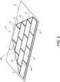
- Figs. 1a to 2 show a first triangular embodiment of the invention.
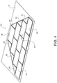
- Figs. 3A to 4 show a second truncated triangular embodiment of the invention.
- Figs. 5 to 8B show a module-to-module coupling system for use with the present system.
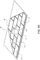
- Figs. 9A through 13 show arrays with a variety of novel-shaped imitation solar modules for use in fitting around various roofing obstructions.
- triangular-shaped solar module 10 is seen.
- Solar module 10 generates no power of its own. Instead, as seen in Fig. 2 , modules 10 are used to round out or fill the corners of an array 50 on the top of a building's roof R. In array 50, triangular-shaped modules 10 do not generate electricity. Instead, only standard photovoltaic modules 20 generate electricity.
- triangular-shaped modules 10 offer aesthetic benefits in that they provide a much more appealing shape for the overall array 50. Specifically, the array 50 does not have the all too common appearance of a staggered module solar array which looks like bricks in an unfinished wall.
- modules 10 may add other structural, electrical and non-aesthetic benefits to the array design.
- modules 10 provide electrical grounding between adjacent photovoltaic modules 20.
- modules 10 provide load balancing and distribution between the adjacent photovoltaic modules 20.
- triangular-shaped modules 10 advantageously need only be connected to adjacent (electricity-generating) modules 20 on two sides. Since the two sides of module 10 which are connected to modules 20 are the shorter sides (leaving only the hypotenuse unconnected to an adjacent module), modules 10 are slightly cantilevered in position. However, due to their triangular shape (and thin body structure), the cantilever effect is minimized. Thus, connections to adjacent modules 20 on only two of the three sides of module 10 are all that is required to support it in position.
- the present system provides an imitation solar module for use in a photovoltaic array, comprising: a flat triangular shaped body portion 12 with a visual representation 14 of a portion of a photovoltaic module displayed on the flat triangular shaped body portion.
- visual representation 14 is simply a decal or printed or otherwise attached "picture" of a triangular section of an actual electricity-generating photovoltaic module.
- module 10 is simply made to look like a fully functioning photovoltaic module. When viewed from the ground, the array 50 will look like a creatively designed and shaped photovoltaic module array. An observer on the ground will not know that only modules 20 generate power while modules 10 simply look like fully functioning electricity-generating modules.
- the decal (or printed picture) that comprises the visual representation 14 is designed such that it looks exactly like a series of standard photovoltaic cells on the surface of the adjacent electricity generating solar modules.
- the decal comprises a substrate made of (PVC free) Envision Print WrapTM Film or ControltacTM Graphic Film made by 3M of Saint Paul, MN with a covering laminate made of or ScotchcalTM Lustre Overlaminate also made by 3M.
- PVC free Envision Print WrapTM Film or ControltacTM Graphic Film made by 3M of Saint Paul, MN with a covering laminate made of or ScotchcalTM Lustre Overlaminate also made by 3M.
- the decal or image is made or printed with a material that is both UV resistant and fade resistant. The image will have the same color as the surface of the neighboring electricity generating modules.
- the module glare, reflectivity, and even the visual images of the traces will be made to match or be the same as those of the fully functioning modules.
- the visual image will match the cell spacing, color, and even texture of a working electricity generating module as closely as possible.
- Even the backsheet color is preferably chosen to match that of the electricity generating modules.
- the image is preferably sufficiently detailed such that it has the randomized cell colors and color gradients typically found on a solar module. (Normally, some cells are slightly darker and some are slightly lighter than one another, or some are slightly greener while others appear more purple than one another).
- the visual representation 14 is designed to mimic these subtle changes. Simply put, it will look like the crystalline structure of a fully functioning solar cell module.
- triangular-shaped module 10 has a thin, planar, flat triangular shaped body portion 12.
- Body portion 12 is given structural rigidity by a first side flange (or flanges) 16 extending downwardly from a first side S1 of the triangular shaped body portion.
- a second side flange (or flanges) 18 extends downwardly from a second side S2 of the triangular shaped body portion.
- a third side flange (or flanges) 19 may extend downwardly from the third side S3 of the triangular shaped body portion.
- sides S1 and S2 may be the roughly same length (thereby giving the corners of body portion two roughly 45 degree angles. Note: in the actual illustration, one angle is approximately 40 degrees whereas the other is approximately 50 degrees. It is to be understood that the present triangle-shaped design encompasses any range of preferred angles (for example from 20 to 70 degrees).
- the longer (hypotenuse) side S3 may preferably be opposite to the 90 degree angle of the triangle.
- an exemplary imitation module 10A may be connected to a first adjacent photovoltaic module 20A which is adjacent in a Y-direction and to a second adjacent photovoltaic module 20B which is adjacent in an X-direction.
- Figs. 3A to 4 illustrated a second (truncated-triangle) embodiment of the imitation solar module.
- solar module 30 has a side groove 32 extending therearound.
- Groove 32 is dimensioned to receive any of a variety of coupling elements therein which can be used to connect the sides of imitation module 30 to adjacent fully functioning electricity generating modules 20.
- Fig. 4 shows six imitation modules 30 together with standard modules 20 forming an aesthetically pleasing shaped array 50.
- modules 10 and 30 may be made of sheet metal, which gives them excellent structural strength to assist with load balancing between the adjacent modules in the array 50, yet is still thin and easy to handle.
- decal 14 can be positioned with one of its edges spaced farther from one of the side edges of the triangle shaped body.
- the position of decal 14 will give the illusion that a side edge of the triangle (from which the edge of the decal is spaced apart) is a raised frame on the side of the imitation module.
- the imitation module is designed such that it appears that the visual representation 14 is at the optimal height such that it appears that it is in the same plane as the rest of the electricity generating solar cells in fully functioning modules 20.
- the main body portion may be made from a thin, planar section of sheet metal, yet still give the illusion that it has the same thickness as the surrounding electricity generating modules.
- the visual representation 14 can be positioned in the same plane as the cells in the surrounding functioning modules, with the side frames 16 and 18 reaching downward from body 12 to provide a platform for couplings which link it to adjacent modules.
- Figs. 5 to 8B illustrate exemplary systems for connecting module 10 to adjacent modules 20.
- a pair of couplings 60 may be placed on two of the sides of the triangle.
- Coupling 60 may have a generally round base 62 and a T-shaped head 64.
- Coupling 60 may be received through a hole in side flanges 16 or 18. It may optionally be riveted in place, (such that it rotates but does not over-tighten), but it is to be understood that the present invention encompasses all suitable fastening mechanisms.
- flanges 16 and 18 extend partially along the respective sides of module 10. It is to be understood that the present invention encompasses embodiments with one or more flanges on any of its sides.
- couplings 60 are simply rotated by approximately 90 degrees to lock T-shaped head 64 into a side groove of the first and second adjacent photovoltaic modules.
- Fig. 8A shows couplings 60 with their T-shaped heads 64 rotated to an unlocked position (such that it can be inserted into a side groove in an adjacent module 20)
- Fig. 8B shows couplings 60 with their T-shaped heads 64 rotated to a locked position (such that it can be securely held within a side groove in an adjacent module 20).
- the present invention also encompasses imitation solar modules that do not have a triangular shape. Examples of such non-triangular modules are seen in Figs. 9A to 13 , as follows.
- a first imitation module 100 has a circular center hole 102 cut therein such that it can be received around a roof vent V.
- a second imitation module 110 has a rectangular center hole 112 cut therein so as not to obstruct the view through a skylight SL therethrough.
- one advantage of imitation modules 100 and 110 is how close they can be built to the sides of the roof obstruction. This provides a structurally solid array on the roof, without having to leave any large gaps which a standard rectangular-shaped module does not fit in the remaining spaces. Again, cutting such sections out of the body portion of the imitation module is facilitated by the use of a thin sheet metal panel as the main body portion 12.
- Fig. 10 shows a different situation where two rows of modules 20 are positioned an irregular distance apart.
- a row of imitation modules 120 can be positioned therebetween to act as "spacers". This situation may occur when one row of modules 20 has to be positioned adjacent to a roof edge, or other obstruction.
- Modules 120 permit a single array 50 to be formed (as opposed to two separated rows formed of modules 20).
- Fig. 11 shows the situation of two small narrow rectangular imitation modules 130A and 130B partially filling a gap between adjacent electricity generating modules 20.
- the space between modules 130A and 130B is left open to accommodate an obstruction in the roof (not shown).
- Fig. 12 shows an imitation solar module 140 having a cut out side section that enables the array to be positioned up close against a roof vent V.
- Fig. 13 shows four imitation modules 150 (surrounded by fully functioning electricity generating modules 20), where each of imitation modules 150 have a rounded corner section cut out such that they can be arranged as shown to provide space for a roof obstruction (such as a vent or chimney).
- a roof obstruction such as a vent or chimney
- the present imitation solar module can be provided in many shapes and sizes. Without limitation, it may be triangular, rectangular or some other regular or irregular shape. It may have straight edges, curved edges or cut-out edges, or any combination of the above.
- the body portion of the imitation module is made of aluminum or galvanized sheet metal.
- the body portion of the imitation module may instead be made of steel, glass, plastic, fiberglass, plastic, or other suitable material.
- the body portion of the imitation module may be made from an actual photovoltaic module that is simply cut to shape. Such a cut or sliced through module will no longer generate any electricity, but it may be cut into a shape such that it can fit into a triangular or other irregularly shaped imitation module.
Landscapes
- Engineering & Computer Science (AREA)
- Architecture (AREA)
- Civil Engineering (AREA)
- Structural Engineering (AREA)
- Roof Covering Using Slabs Or Stiff Sheets (AREA)
- Photovoltaic Devices (AREA)
Claims (15)
- Imitationssolarmodul (10) zur Verwendung in einer Photovoltaikgruppe (50), umfassend:einen flachen, im Allgemeinen planaren Körperabschnitt (12) ;eine visuelle Darstellung eines Photovoltaikmoduls, die auf dem flachen, im Allgemeinen planaren Körperabschnitt angezeigt wird;einen ersten Seitenflansch (16) des Körperabschnitts (12), der sich von dem flachen, im Allgemeinen planaren Körperabschnitt nur nach unten erstreckt, wobei der erste Seitenflansch dazu geeignet ist, mit einem ersten angrenzenden Photovoltaikmodul verbunden zu werden; undeinen zweiten Seitenflansch (18) des Körperabschnitts (12), der sich von dem flachen, im Allgemeinen planaren Körperabschnitt nur nach unten erstreckt, wobei der zweite Seitenflansch dazu geeignet ist, mit einem zweiten angrenzenden Photovoltaikmodul verbunden zu werden; wobei der erste und der zweite Seitenflansch sich jeweils nur teilweise entlang jeweiligen Seiten des planaren Körperabschnitts erstrecken.
- Imitationssolarmodul nach Anspruch 1, wobei der erste und der zweite Seitenflansch dazu geeignet sind, mit dem ersten (20A) und dem zweiten (20B) angrenzenden Photovoltaikmodul durch mindestens eine Kopplung auf jedem von dem ersten und dem zweiten Seitenflansch verbunden zu werden, die sich von dem flachen Körperabschnitt nach unten erstrecken.
- Imitationssolarmodul nach Anspruch 1, wobei der planare Körperabschnitt ein flacher, dreieckig geformter Körperabschnitt ist;
wobei der erste Seitenflansch ein erster Seitenflansch ist, der sich von einer ersten Seite des dreieckig geformten Körperabschnitts nach unten erstreckt;
wobei das Imitationssolarmodul ferner mindestens eine Kopplung auf dem ersten Seitenflansch zum Verbinden des dreieckig geformten Körperabschnitts mit einem ersten angrenzenden Photovoltaikmodul umfasst;
wobei der zweite Seitenflansch ein zweiter Seitenflansch ist, der sich von einer zweiten Seite des dreieckig geformten Körperabschnitts nach unten erstreckt; und
wobei das Imitationssolarmodul ferner mindestens eine Kopplung auf dem zweiten Seitenflansch zum Verbinden des dreieckig geformten Körperabschnitts mit einem zweiten angrenzenden Photovoltaikmodul umfasst. - Imitationssolarmodul nach Anspruch 3, wobei das erste angrenzende Photovoltaikmodul in einer X-Richtung angrenzend ist und das zweite angrenzende Photovoltaikmodul in einer Y-Richtung angrenzend ist.
- Imitationssolarmodul nach Anspruch 1, wobei sich die mindestens eine Kopplung (60) auf dem ersten Seitenflansch durch den ersten Seitenflansch erstreckt und so bemessen ist, dass sie um etwa 90 Grad gedreht werden kann, um in eine Seitennut (32) des ersten und des zweiten Photovoltaikmoduls einzurasten.
- Imitationssolarmodul nach Anspruch 1 oder 3, wobei die visuelle Darstellung eines Abschnitts eines Photovoltaikmoduls ein Aufkleber (14) ist, der auf der Oberseite des Körperabschnitts befestigt ist.
- Imitationssolarmodul nach Anspruch 1 oder 3, wobei die Erscheinung der visuellen Darstellung auf dem Körperabschnitt die Farbe, Farbverläufe und Zelloberflächenmerkmale imitiert, die in einem Strom erzeugenden Solarmodul zu sehen sind.
- Imitationssolarmodul nach Anspruch 1 oder 3, wobei das Imitationssolarmodul keine Strom erzeugenden Elemente umfasst.
- Imitationssolarmodul nach Anspruch 1 oder 2, wobei jede Kopplung ein Paar von Kopplungen umfasst.
- Imitationssolarmodul nach Anspruch 1, wobei der flache Körperabschnitt rechteckig ist.
- Imitationssolarmodul nach Anspruch 1, wobei der flache Körperabschnitt eine gekrümmte Kante aufweist.
- Imitationssolarmodul nach Anspruch 1, wobei der flache Körperabschnitt einen ausgeschnittenen Abschnitt aufweist.
- Gruppe von Strom erzeugenden Solarmodulen und Imitationssolarmodulen, umfassend:(a) mehrere Strom erzeugende Solarmodule;(b) mehrere Imitationssolarmodule gemäß Anspruch 1; und(c) mehrere Kopplungen, die die Imitationssolarmodule mit den Strom erzeugenden Solarmodulen verbinden, um eine Gruppe von Strom erzeugenden Solarmodulen und Imitationssolarmodulen zu bilden.
- Gruppe nach Anspruch 13, wobei die mehreren Imitationssolarmodule eine dreieckige Form haben.
- Imitationssolarmodul nach Anspruch 1 oder 3 oder Gruppe nach Anspruch 13, wobei der flache Körperabschnitt aus Stahlblech gefertigt ist.
Priority Applications (1)
| Application Number | Priority Date | Filing Date | Title |
|---|---|---|---|
| EP20156626.2A EP3678193A1 (de) | 2014-04-18 | 2015-04-10 | Imitationssolarmodul zur verwendung in einer versetzten oder unregelmässig geformten solarzellengruppe |
Applications Claiming Priority (3)
| Application Number | Priority Date | Filing Date | Title |
|---|---|---|---|
| US14/256,657 US8946540B1 (en) | 2014-04-18 | 2014-04-18 | Imitation solar module for use in a staggered or irregularly shaped solar array |
| US14/577,222 US20150303865A1 (en) | 2014-04-18 | 2014-12-19 | Imitation Solar Module For Use In A Staggered Or Irregularly Shaped Solar Array |
| PCT/US2015/025269 WO2015160644A1 (en) | 2014-04-18 | 2015-04-10 | An imitation solar module for use in a staggered or irregularly shaped solar array |
Related Child Applications (1)
| Application Number | Title | Priority Date | Filing Date |
|---|---|---|---|
| EP20156626.2A Division EP3678193A1 (de) | 2014-04-18 | 2015-04-10 | Imitationssolarmodul zur verwendung in einer versetzten oder unregelmässig geformten solarzellengruppe |
Publications (3)
| Publication Number | Publication Date |
|---|---|
| EP3090484A1 EP3090484A1 (de) | 2016-11-09 |
| EP3090484A4 EP3090484A4 (de) | 2017-08-09 |
| EP3090484B1 true EP3090484B1 (de) | 2020-02-12 |
Family
ID=52395630
Family Applications (2)
| Application Number | Title | Priority Date | Filing Date |
|---|---|---|---|
| EP20156626.2A Pending EP3678193A1 (de) | 2014-04-18 | 2015-04-10 | Imitationssolarmodul zur verwendung in einer versetzten oder unregelmässig geformten solarzellengruppe |
| EP15779940.4A Active EP3090484B1 (de) | 2014-04-18 | 2015-04-10 | Imitationssolarmodul zur verwendung in einer versetzten oder unregelmässig geformten solarzellengruppe |
Family Applications Before (1)
| Application Number | Title | Priority Date | Filing Date |
|---|---|---|---|
| EP20156626.2A Pending EP3678193A1 (de) | 2014-04-18 | 2015-04-10 | Imitationssolarmodul zur verwendung in einer versetzten oder unregelmässig geformten solarzellengruppe |
Country Status (4)
| Country | Link |
|---|---|
| US (2) | US8946540B1 (de) |
| EP (2) | EP3678193A1 (de) |
| CN (2) | CN106416057B (de) |
| WO (1) | WO2015160644A1 (de) |
Families Citing this family (19)
| Publication number | Priority date | Publication date | Assignee | Title |
|---|---|---|---|---|
| US9134044B2 (en) | 2010-01-25 | 2015-09-15 | Vermont Slate & Copper Services, Inc. | Roof mount assembly |
| US9447988B2 (en) | 2010-01-25 | 2016-09-20 | Rillito Rive Solar, LLC | Roof mount assembly |
| US20110000544A1 (en) * | 2009-07-02 | 2011-01-06 | West John R | Drop-in connection apparatus, system, and method for photovoltaic arrays |
| US9175478B2 (en) | 2012-05-29 | 2015-11-03 | Vermont Slate & Copper Services, Inc. | Snow fence for a solar panel |
| US9973142B2 (en) | 2013-03-06 | 2018-05-15 | Vermont Slate and Copper Services, Inc. | Snow fence for a solar panel |
| US10256765B2 (en) | 2013-06-13 | 2019-04-09 | Building Materials Investment Corporation | Roof integrated photovoltaic system |
| US9985575B2 (en) * | 2014-04-07 | 2018-05-29 | Rillito River Solar, Llc | Height adjustment bracket for roof applications |
| US9431953B2 (en) | 2014-10-31 | 2016-08-30 | Rillito River Solar, Llc | Height adjustment bracket for roof applications |
| US12107530B2 (en) | 2014-04-07 | 2024-10-01 | EcoFasten Solar, LLC | Height adjustment bracket for roof applications |
| US9985579B2 (en) | 2016-04-12 | 2018-05-29 | Preformed Line Products Co. | Mounting assembly for mounting a solar panel |
| JP6678063B2 (ja) * | 2016-05-20 | 2020-04-08 | ソーラーフロンティア株式会社 | コーナー部材の保持機構 |
| USD844419S1 (en) * | 2016-08-19 | 2019-04-02 | Solarcity Corporation | Coupling |
| US10469023B2 (en) | 2016-09-12 | 2019-11-05 | EcoFasten Solar, LLC | Roof mounting system |
| JP6976068B2 (ja) * | 2017-03-29 | 2021-12-01 | ソーラーフロンティア株式会社 | 側方部材、パネルアレイ構造体及び側方部材の設置方法 |
| JP7036619B2 (ja) * | 2018-02-21 | 2022-03-15 | 積水化学工業株式会社 | 太陽電池の設置構造、屋根および屋根の補修方法 |
| WO2019163152A1 (ja) * | 2018-02-26 | 2019-08-29 | 三菱電機株式会社 | 太陽電池モジュールおよび太陽電池モジュールの製造方法 |
| EP3792984B1 (de) | 2019-09-13 | 2021-11-24 | g-neration.energy AG | Verfahren zur herstellung eines solarmoduls |
| CZ2024482A3 (cs) * | 2024-12-12 | 2026-01-28 | Wienerberger s.r.o. | Střešní redukční adaptér a střecha |
| USD1126137S1 (en) | 2025-05-13 | 2026-05-12 | Kajal Sheth | Rhombus-shaped solar panel |
Family Cites Families (19)
| Publication number | Priority date | Publication date | Assignee | Title |
|---|---|---|---|---|
| US2010032A (en) * | 1931-03-19 | 1935-08-06 | Coxhead Ralph C Corp | Means and the method of making type shuttles for typewriting machines |
| JPH10131441A (ja) * | 1996-11-05 | 1998-05-19 | Misawa Homes Co Ltd | 屋根設置用パネル |
| JP3269778B2 (ja) * | 1996-11-05 | 2002-04-02 | ミサワホーム株式会社 | 屋根構造体 |
| JPH1136541A (ja) | 1997-07-24 | 1999-02-09 | Sekisui House Ltd | 太陽電池モジュールを模造したダミーモジュール |
| JP3586083B2 (ja) | 1997-11-13 | 2004-11-10 | キヤノン株式会社 | 太陽電池モジュールの配置方法及び太陽電池モジュールアレイ |
| JP3937654B2 (ja) | 1998-06-30 | 2007-06-27 | キヤノン株式会社 | 太陽電池モジュール、その設置方法、ならびにそれを用いた太陽光発電装置および屋根 |
| JP2000323739A (ja) * | 1999-05-14 | 2000-11-24 | Kanegafuchi Chem Ind Co Ltd | 薄膜太陽電池ダミーモジュール |
| JP4226153B2 (ja) * | 1999-07-15 | 2009-02-18 | 株式会社カネカ | 薄膜太陽電池ダミーモジュール |
| JP2001098703A (ja) * | 1999-07-23 | 2001-04-10 | Kanegafuchi Chem Ind Co Ltd | 屋根構造体及び瓦葺方法 |
| US20030154667A1 (en) | 2002-02-20 | 2003-08-21 | Dinwoodie Thomas L. | Shingle system |
| JP4684874B2 (ja) * | 2005-12-13 | 2011-05-18 | 株式会社屋根技術研究所 | 太陽電池モジュール枠体 |
| US7731383B2 (en) * | 2007-02-02 | 2010-06-08 | Inovus Solar, Inc. | Solar-powered light pole and LED light fixture |
| NL2001380C2 (nl) * | 2008-03-17 | 2009-09-21 | Ubbink Bv | Hellend dak met zonnepaneelhouder. |
| EP2350535A4 (de) * | 2008-10-11 | 2014-01-22 | Solar Power Inc | Solarzellensysteme mit effizienter installation |
| US8276330B2 (en) | 2008-12-12 | 2012-10-02 | Applied Energy Technologies | Modular solar panel racking system |
| US20100326488A1 (en) * | 2009-06-26 | 2010-12-30 | Robert Aue | Simulated photovoltaic module and array including same |
| US20120298188A1 (en) * | 2009-10-06 | 2012-11-29 | Zep Solar, Inc. | Method and Apparatus for Forming and Mounting a Photovoltaic Array |
| US10187005B2 (en) * | 2012-10-01 | 2019-01-22 | Building Materials Investment Corporation | Solar roof panel system with edge and surface treatments |
| CN103715286A (zh) * | 2013-12-27 | 2014-04-09 | 安徽长远绿色能源有限公司 | 新型建筑用光伏构件 |
-
2014
- 2014-04-18 US US14/256,657 patent/US8946540B1/en active Active
- 2014-12-19 US US14/577,222 patent/US20150303865A1/en not_active Abandoned
-
2015
- 2015-04-10 WO PCT/US2015/025269 patent/WO2015160644A1/en not_active Ceased
- 2015-04-10 EP EP20156626.2A patent/EP3678193A1/de active Pending
- 2015-04-10 EP EP15779940.4A patent/EP3090484B1/de active Active
- 2015-04-10 CN CN201580007363.0A patent/CN106416057B/zh active Active
- 2015-04-17 CN CN201520350611.9U patent/CN204947972U/zh not_active Expired - Lifetime
Non-Patent Citations (1)
| Title |
|---|
| None * |
Also Published As
| Publication number | Publication date |
|---|---|
| EP3090484A4 (de) | 2017-08-09 |
| US20150303865A1 (en) | 2015-10-22 |
| WO2015160644A1 (en) | 2015-10-22 |
| CN106416057A (zh) | 2017-02-15 |
| CN106416057B (zh) | 2019-04-23 |
| US8946540B1 (en) | 2015-02-03 |
| EP3678193A1 (de) | 2020-07-08 |
| CN204947972U (zh) | 2016-01-06 |
| EP3090484A1 (de) | 2016-11-09 |
Similar Documents
| Publication | Publication Date | Title |
|---|---|---|
| US8946540B1 (en) | Imitation solar module for use in a staggered or irregularly shaped solar array | |
| US12525912B2 (en) | Solar roof panel system with edge and surface treatments | |
| US11705855B2 (en) | Interlocking BIPV roof tile with backer | |
| US9127863B2 (en) | Mounting for solar panels | |
| US10790777B2 (en) | Flexible solar roofing modules | |
| US10855220B2 (en) | Hinged building integrated photovoltaic roof tile modules | |
| US20100326488A1 (en) | Simulated photovoltaic module and array including same | |
| US20120312373A1 (en) | Solar Roof Panel Assembly and Method for Installation | |
| US10505495B2 (en) | PV tile mounting system | |
| US10812012B2 (en) | Hinging inverted seam module mounting system | |
| NO20231108A1 (en) | Solar cell wall panel | |
| WO2002039505A1 (en) | Building with sandwich panels | |
| WO2024153804A1 (en) | Replacement roof tile; optionally with solar panel | |
| DK202631130A1 (en) | Solar cell wall panel | |
| EP4295482A1 (de) | Vorgefertigte fassadenplatte | |
| JP5751468B2 (ja) | 瓦屋根への外設構造の構築法、及び外装構造 |
Legal Events
| Date | Code | Title | Description |
|---|---|---|---|
| PUAI | Public reference made under article 153(3) epc to a published international application that has entered the european phase |
Free format text: ORIGINAL CODE: 0009012 |
|
| 17P | Request for examination filed |
Effective date: 20160805 |
|
| AK | Designated contracting states |
Kind code of ref document: A1 Designated state(s): AL AT BE BG CH CY CZ DE DK EE ES FI FR GB GR HR HU IE IS IT LI LT LU LV MC MK MT NL NO PL PT RO RS SE SI SK SM TR |
|
| AX | Request for extension of the european patent |
Extension state: BA ME |
|
| REG | Reference to a national code |
Ref country code: DE Ref legal event code: R079 Ref document number: 602015046869 Country of ref document: DE Free format text: PREVIOUS MAIN CLASS: H02S0020260000 Ipc: H01L0031042000 |
|
| DAV | Request for validation of the european patent (deleted) | ||
| DAX | Request for extension of the european patent (deleted) | ||
| A4 | Supplementary search report drawn up and despatched |
Effective date: 20170711 |
|
| RIC1 | Information provided on ipc code assigned before grant |
Ipc: H01L 31/042 20140101AFI20170706BHEP Ipc: H02S 20/25 20140101ALI20170706BHEP Ipc: H02S 20/23 20140101ALI20170706BHEP |
|
| STAA | Information on the status of an ep patent application or granted ep patent |
Free format text: STATUS: EXAMINATION IS IN PROGRESS |
|
| 17Q | First examination report despatched |
Effective date: 20180425 |
|
| GRAP | Despatch of communication of intention to grant a patent |
Free format text: ORIGINAL CODE: EPIDOSNIGR1 |
|
| STAA | Information on the status of an ep patent application or granted ep patent |
Free format text: STATUS: GRANT OF PATENT IS INTENDED |
|
| RAP1 | Party data changed (applicant data changed or rights of an application transferred) |
Owner name: TESLA, INC. |
|
| INTG | Intention to grant announced |
Effective date: 20190823 |
|
| RIN1 | Information on inventor provided before grant (corrected) |
Inventor name: HAINES, ALEX Inventor name: TRIPP, KYLE Inventor name: WEST, JACK RAYMOND |
|
| GRAS | Grant fee paid |
Free format text: ORIGINAL CODE: EPIDOSNIGR3 |
|
| GRAA | (expected) grant |
Free format text: ORIGINAL CODE: 0009210 |
|
| STAA | Information on the status of an ep patent application or granted ep patent |
Free format text: STATUS: THE PATENT HAS BEEN GRANTED |
|
| AK | Designated contracting states |
Kind code of ref document: B1 Designated state(s): AL AT BE BG CH CY CZ DE DK EE ES FI FR GB GR HR HU IE IS IT LI LT LU LV MC MK MT NL NO PL PT RO RS SE SI SK SM TR |
|
| REG | Reference to a national code |
Ref country code: GB Ref legal event code: FG4D |
|
| REG | Reference to a national code |
Ref country code: CH Ref legal event code: EP |
|
| REG | Reference to a national code |
Ref country code: AT Ref legal event code: REF Ref document number: 1233245 Country of ref document: AT Kind code of ref document: T Effective date: 20200215 |
|
| REG | Reference to a national code |
Ref country code: IE Ref legal event code: FG4D |
|
| REG | Reference to a national code |
Ref country code: DE Ref legal event code: R096 Ref document number: 602015046869 Country of ref document: DE |
|
| PG25 | Lapsed in a contracting state [announced via postgrant information from national office to epo] |
Ref country code: NO Free format text: LAPSE BECAUSE OF FAILURE TO SUBMIT A TRANSLATION OF THE DESCRIPTION OR TO PAY THE FEE WITHIN THE PRESCRIBED TIME-LIMIT Effective date: 20200512 Ref country code: RS Free format text: LAPSE BECAUSE OF FAILURE TO SUBMIT A TRANSLATION OF THE DESCRIPTION OR TO PAY THE FEE WITHIN THE PRESCRIBED TIME-LIMIT Effective date: 20200212 Ref country code: FI Free format text: LAPSE BECAUSE OF FAILURE TO SUBMIT A TRANSLATION OF THE DESCRIPTION OR TO PAY THE FEE WITHIN THE PRESCRIBED TIME-LIMIT Effective date: 20200212 |
|
| REG | Reference to a national code |
Ref country code: LT Ref legal event code: MG4D |
|
| REG | Reference to a national code |
Ref country code: NL Ref legal event code: MP Effective date: 20200212 |
|
| PG25 | Lapsed in a contracting state [announced via postgrant information from national office to epo] |
Ref country code: SE Free format text: LAPSE BECAUSE OF FAILURE TO SUBMIT A TRANSLATION OF THE DESCRIPTION OR TO PAY THE FEE WITHIN THE PRESCRIBED TIME-LIMIT Effective date: 20200212 Ref country code: LV Free format text: LAPSE BECAUSE OF FAILURE TO SUBMIT A TRANSLATION OF THE DESCRIPTION OR TO PAY THE FEE WITHIN THE PRESCRIBED TIME-LIMIT Effective date: 20200212 Ref country code: HR Free format text: LAPSE BECAUSE OF FAILURE TO SUBMIT A TRANSLATION OF THE DESCRIPTION OR TO PAY THE FEE WITHIN THE PRESCRIBED TIME-LIMIT Effective date: 20200212 Ref country code: IS Free format text: LAPSE BECAUSE OF FAILURE TO SUBMIT A TRANSLATION OF THE DESCRIPTION OR TO PAY THE FEE WITHIN THE PRESCRIBED TIME-LIMIT Effective date: 20200612 Ref country code: GR Free format text: LAPSE BECAUSE OF FAILURE TO SUBMIT A TRANSLATION OF THE DESCRIPTION OR TO PAY THE FEE WITHIN THE PRESCRIBED TIME-LIMIT Effective date: 20200513 Ref country code: BG Free format text: LAPSE BECAUSE OF FAILURE TO SUBMIT A TRANSLATION OF THE DESCRIPTION OR TO PAY THE FEE WITHIN THE PRESCRIBED TIME-LIMIT Effective date: 20200512 |
|
| PG25 | Lapsed in a contracting state [announced via postgrant information from national office to epo] |
Ref country code: NL Free format text: LAPSE BECAUSE OF FAILURE TO SUBMIT A TRANSLATION OF THE DESCRIPTION OR TO PAY THE FEE WITHIN THE PRESCRIBED TIME-LIMIT Effective date: 20200212 |
|
| PG25 | Lapsed in a contracting state [announced via postgrant information from national office to epo] |
Ref country code: RO Free format text: LAPSE BECAUSE OF FAILURE TO SUBMIT A TRANSLATION OF THE DESCRIPTION OR TO PAY THE FEE WITHIN THE PRESCRIBED TIME-LIMIT Effective date: 20200212 Ref country code: CZ Free format text: LAPSE BECAUSE OF FAILURE TO SUBMIT A TRANSLATION OF THE DESCRIPTION OR TO PAY THE FEE WITHIN THE PRESCRIBED TIME-LIMIT Effective date: 20200212 Ref country code: EE Free format text: LAPSE BECAUSE OF FAILURE TO SUBMIT A TRANSLATION OF THE DESCRIPTION OR TO PAY THE FEE WITHIN THE PRESCRIBED TIME-LIMIT Effective date: 20200212 Ref country code: SM Free format text: LAPSE BECAUSE OF FAILURE TO SUBMIT A TRANSLATION OF THE DESCRIPTION OR TO PAY THE FEE WITHIN THE PRESCRIBED TIME-LIMIT Effective date: 20200212 Ref country code: ES Free format text: LAPSE BECAUSE OF FAILURE TO SUBMIT A TRANSLATION OF THE DESCRIPTION OR TO PAY THE FEE WITHIN THE PRESCRIBED TIME-LIMIT Effective date: 20200212 Ref country code: LT Free format text: LAPSE BECAUSE OF FAILURE TO SUBMIT A TRANSLATION OF THE DESCRIPTION OR TO PAY THE FEE WITHIN THE PRESCRIBED TIME-LIMIT Effective date: 20200212 Ref country code: DK Free format text: LAPSE BECAUSE OF FAILURE TO SUBMIT A TRANSLATION OF THE DESCRIPTION OR TO PAY THE FEE WITHIN THE PRESCRIBED TIME-LIMIT Effective date: 20200212 Ref country code: PT Free format text: LAPSE BECAUSE OF FAILURE TO SUBMIT A TRANSLATION OF THE DESCRIPTION OR TO PAY THE FEE WITHIN THE PRESCRIBED TIME-LIMIT Effective date: 20200705 Ref country code: SK Free format text: LAPSE BECAUSE OF FAILURE TO SUBMIT A TRANSLATION OF THE DESCRIPTION OR TO PAY THE FEE WITHIN THE PRESCRIBED TIME-LIMIT Effective date: 20200212 |
|
| REG | Reference to a national code |
Ref country code: DE Ref legal event code: R097 Ref document number: 602015046869 Country of ref document: DE |
|
| REG | Reference to a national code |
Ref country code: AT Ref legal event code: MK05 Ref document number: 1233245 Country of ref document: AT Kind code of ref document: T Effective date: 20200212 |
|
| PG25 | Lapsed in a contracting state [announced via postgrant information from national office to epo] |
Ref country code: MC Free format text: LAPSE BECAUSE OF FAILURE TO SUBMIT A TRANSLATION OF THE DESCRIPTION OR TO PAY THE FEE WITHIN THE PRESCRIBED TIME-LIMIT Effective date: 20200212 |
|
| REG | Reference to a national code |
Ref country code: CH Ref legal event code: PL |
|
| PLBE | No opposition filed within time limit |
Free format text: ORIGINAL CODE: 0009261 |
|
| STAA | Information on the status of an ep patent application or granted ep patent |
Free format text: STATUS: NO OPPOSITION FILED WITHIN TIME LIMIT |
|
| 26N | No opposition filed |
Effective date: 20201113 |
|
| PG25 | Lapsed in a contracting state [announced via postgrant information from national office to epo] |
Ref country code: AT Free format text: LAPSE BECAUSE OF FAILURE TO SUBMIT A TRANSLATION OF THE DESCRIPTION OR TO PAY THE FEE WITHIN THE PRESCRIBED TIME-LIMIT Effective date: 20200212 Ref country code: IT Free format text: LAPSE BECAUSE OF FAILURE TO SUBMIT A TRANSLATION OF THE DESCRIPTION OR TO PAY THE FEE WITHIN THE PRESCRIBED TIME-LIMIT Effective date: 20200212 Ref country code: CH Free format text: LAPSE BECAUSE OF NON-PAYMENT OF DUE FEES Effective date: 20200430 Ref country code: LI Free format text: LAPSE BECAUSE OF NON-PAYMENT OF DUE FEES Effective date: 20200430 Ref country code: LU Free format text: LAPSE BECAUSE OF NON-PAYMENT OF DUE FEES Effective date: 20200410 |
|
| REG | Reference to a national code |
Ref country code: BE Ref legal event code: MM Effective date: 20200430 |
|
| PG25 | Lapsed in a contracting state [announced via postgrant information from national office to epo] |
Ref country code: BE Free format text: LAPSE BECAUSE OF NON-PAYMENT OF DUE FEES Effective date: 20200430 Ref country code: PL Free format text: LAPSE BECAUSE OF FAILURE TO SUBMIT A TRANSLATION OF THE DESCRIPTION OR TO PAY THE FEE WITHIN THE PRESCRIBED TIME-LIMIT Effective date: 20200212 Ref country code: SI Free format text: LAPSE BECAUSE OF FAILURE TO SUBMIT A TRANSLATION OF THE DESCRIPTION OR TO PAY THE FEE WITHIN THE PRESCRIBED TIME-LIMIT Effective date: 20200212 |
|
| PG25 | Lapsed in a contracting state [announced via postgrant information from national office to epo] |
Ref country code: IE Free format text: LAPSE BECAUSE OF NON-PAYMENT OF DUE FEES Effective date: 20200410 |
|
| PG25 | Lapsed in a contracting state [announced via postgrant information from national office to epo] |
Ref country code: TR Free format text: LAPSE BECAUSE OF FAILURE TO SUBMIT A TRANSLATION OF THE DESCRIPTION OR TO PAY THE FEE WITHIN THE PRESCRIBED TIME-LIMIT Effective date: 20200212 Ref country code: MT Free format text: LAPSE BECAUSE OF FAILURE TO SUBMIT A TRANSLATION OF THE DESCRIPTION OR TO PAY THE FEE WITHIN THE PRESCRIBED TIME-LIMIT Effective date: 20200212 Ref country code: CY Free format text: LAPSE BECAUSE OF FAILURE TO SUBMIT A TRANSLATION OF THE DESCRIPTION OR TO PAY THE FEE WITHIN THE PRESCRIBED TIME-LIMIT Effective date: 20200212 |
|
| PG25 | Lapsed in a contracting state [announced via postgrant information from national office to epo] |
Ref country code: MK Free format text: LAPSE BECAUSE OF FAILURE TO SUBMIT A TRANSLATION OF THE DESCRIPTION OR TO PAY THE FEE WITHIN THE PRESCRIBED TIME-LIMIT Effective date: 20200212 Ref country code: AL Free format text: LAPSE BECAUSE OF FAILURE TO SUBMIT A TRANSLATION OF THE DESCRIPTION OR TO PAY THE FEE WITHIN THE PRESCRIBED TIME-LIMIT Effective date: 20200212 |
|
| P01 | Opt-out of the competence of the unified patent court (upc) registered |
Effective date: 20230512 |
|
| REG | Reference to a national code |
Ref country code: DE Ref legal event code: R079 Ref document number: 602015046869 Country of ref document: DE Free format text: PREVIOUS MAIN CLASS: H01L0031042000 Ipc: H10F0019000000 |
|
| PGFP | Annual fee paid to national office [announced via postgrant information from national office to epo] |
Ref country code: DE Payment date: 20250428 Year of fee payment: 11 |
|
| PGFP | Annual fee paid to national office [announced via postgrant information from national office to epo] |
Ref country code: GB Payment date: 20250422 Year of fee payment: 11 |
|
| PGFP | Annual fee paid to national office [announced via postgrant information from national office to epo] |
Ref country code: FR Payment date: 20250424 Year of fee payment: 11 |