EP3090270B1 - Device and method for inspecting an alternator - Google Patents
Device and method for inspecting an alternator Download PDFInfo
- Publication number
- EP3090270B1 EP3090270B1 EP14833258.8A EP14833258A EP3090270B1 EP 3090270 B1 EP3090270 B1 EP 3090270B1 EP 14833258 A EP14833258 A EP 14833258A EP 3090270 B1 EP3090270 B1 EP 3090270B1
- Authority
- EP
- European Patent Office
- Prior art keywords
- probe
- moving
- alternator
- driving element
- deflecting
- Prior art date
- Legal status (The legal status is an assumption and is not a legal conclusion. Google has not performed a legal analysis and makes no representation as to the accuracy of the status listed.)
- Active
Links
Images

Classifications
-
- G—PHYSICS
- G01—MEASURING; TESTING
- G01R—MEASURING ELECTRIC VARIABLES; MEASURING MAGNETIC VARIABLES
- G01R31/00—Arrangements for testing electric properties; Arrangements for locating electric faults; Arrangements for electrical testing characterised by what is being tested not provided for elsewhere
- G01R31/34—Testing dynamo-electric machines
Definitions
- the present invention relates to a device and to a method for inspecting an alternator.
- the present invention relates to a device and to a method for inspecting parts of a stator of an alternator of a plant for electric energy production with rotor inserted.
- Alternators for generating electric energy often contemplate activities involving the inspection of parts of the stator, with the aim of preventing the occurrence of failures. Sometimes, such inspections are carried out following the detection of anomalies or malfunctions of the alternator.
- Such a monitoring activity is usually carried out by means of inspection probes of known type.
- inspection probes are disclosed in documents US5105658 , EP0684483 , US2002/135383 , US2005/093536 , EP2071343 .
- the present invention relates to a device for inspecting an alternator according to claim 1.
- the present invention relates to a method for inspecting an alternator according to claim 11.
- numeral 1 indicates an alternator, as a whole, which extends along a longitudinal axis A and comprises a rotor 2, which is the inductor and is the movable part of turboalternator 1, and a stator 3, which is the armature and is the fixed part of the turboalternator.
- Rotor 2 is substantially cylindrical shaped and rotates - moved by a turbine (not illustrated) - about its own axis, which coincides with the longitudinal axis A of alternator 1.
- Stator 3 is a hollow cylinder which is coaxial with rotor 2, which extends outside rotor 2.
- the space comprised between rotor 2 and stator 3 is called air gap 4.
- Stator 3 comprises a cylindrical core 5, which extends along the longitudinal axis A, a plurality of electrical windings 6 (only some of which are shown diagrammatically in figure 1 ), two heads 7 arranged at the ends of stator 3 and of terminals 8 for drawing the current.
- the windings 6 are crossed by a current induced by the rotation of rotor 2.
- the cylindrical core 5 has a plurality of axial grooves, called slots 10, which extend for the entire length of the cylindrical core 5.
- the slots 10 are separated and delimited by longitudinal projections 11, which are parallel to axis A.
- Each winding 6 comprises a plurality of conductor bars 12, each of which is arranged in part along a defined path inside the slots 10, and in part at the heads 7 ( figure 1 ).
- Each electrical winding 6 is therefore arranged in several slots 10. In particular, each winding 6 passes through a first slot 10, comes out of the first slot 10 at a head 7 ( figure 1 ) to then enter a second slot 10 and comes out at the opposite head 7 ( figure 1 ), enters a third slot 10 and so on, for a number of times defined in the project.
- each slot 10 accommodates two bars 12: a hollow external bar 12a and a hollow internal bar 12b.
- Figures 1 and 2 show a device 15 for inspecting alternator 1 according to the present invention.
- device 15 is arranged in the air gap 4 and is configured for inspecting stator 3 of alternator 1 with rotor 2 assembled.
- Device 15 comprises a carriage 16, a probe 17, first moving means 20 configured for moving probe 17 along a moving axis V belonging to a moving plane (shown in figures 3 and 4 ), second moving means 21 (diagrammatically shown in figure 1 ) connected to probe 17 and configured for moving a free end 22 of probe 17, at least a first driving element 24 (best shown in figures 3 and 4 ) shaped for deflecting probe 17 along a first direction D1 transversal to the moving axis V on a first side of the moving plane, a control station 25 and a monitor 26 connected to probe 17.
- carriage 16 is arranged preferably resting on core 5 and is movable along a direction parallel to axis A. In the non-limiting embodiment herein described and illustrated, carriage 16 moves substantially along the moving axis V.
- carriage 16 is provided with a moving system 28 (partly shown in figure 4 ) which is controlled remotely by means of the control station 25.
- the moving system 28 comprises an electric motor (not illustrated in the accompanying figures for simplicity), two tracks 30 (one of which is diagrammatically illustrated in figure 4 ) and drive means (not illustrated in the accompanying figures for simplicity) configured to transmit the motion of the electric motor to the tracks 30.
- each track 30 is arranged resting on a respective projection 11 of core 5 of stator 3.
- the tracks 30 and/or the drive means are coupled to elements made of magnetic material so as to ensure a secure and reliable adhesion of the tracks 30 to the respective projections 11 of the entire core 5, including the upper portion of core 5.
- Variants (not illustrated) provide for other elements of carriage 16 to be made of magnetic material to ensure the adhesion between carriage 16 and the projections 11 to which carriage 16 is to be coupled.
- carriage 16 comprises two main bodies 34, each of which is coupled to a respective track 30, a head 35 and a middle portion 36 arranged between the head and the two main bodies 34.
- the two main bodies 34 are arranged side by side, extend parallel to one another and are coupled to each other by means of a connection system 37.
- connection system 37 is configured so that the distance between the main bodies 34 is adjustable.
- the connection system 37 comprises two tubular elements 38, telescopic tubular elements.
- the distance between the centers of the tracks 30 may be adjusted so that each track 30 is coupled to the respective projection 11 of the cylindrical core 5 of stator 3. Thereby, device 15 according to the present invention may be engaged on alternators of different sizes in which the distance is variable between the projections 11 of core 5.
- carriage 16 may comprise a single main body coupled to the tracks 30 and that the distance between the centers of the tracks 30 is in any case adjustable.
- the middle portion 36 is preferably coupled to one of the two main bodies 34 and supports probe 15 along the moving axis V.
- the middle portion 36 comprises an accommodating seat 40 configured for accommodating the first moving means 20 of probe 17.
- the first moving means 20 of probe 17 comprise an electric motor (not illustrated for simplicity), at least one roller 41 arranged against probe 17, and drive means for transmitting the motion of the motor to roller 41.
- Roller 41 rotates with respect to an axis O which is orthogonal to the moving axis V of probe 17.
- Roller 41 may rotate in a first direction V1 to obtain a forward movement of probe 17 along the moving axis V, and in a second direction V2 to obtain a reverse movement of probe 17 along the moving axis V.
- the operation of the electric motor of the moving means 20 and the setting of the direction of rotation of roller 41 is automatically regulated by the control station 25 or following a manual adjustment.
- the operation of the electric motor determines the advancing of carriage 16 along the moving axis V.
- the second moving means 21 are configured to move the free end 22 of probe 17.
- head 35 comprises a main conduit 43, the first driving element 24, which extends substantially along the moving axis V, a second driving element 44 and a third driving element 45.
- the second driving element 44 and the third driving element 45 are arranged preferably symmetrical with respect to the moving axis V and extend along respective directions.
- the second driving element 44 and the third driving element 45 are shaped so as to deflect probe 17 in a respective second direction D2 and in a respective third direction D3 on the first side of the moving plane.
- the second direction D2 and the third direction D3 are both transversal to the moving axis V of probe 17.
- the main conduit 43 drives probe 17 along the moving axis V and is in communication with the first driving element 24, the second driving element 44 and the third driving element 45 by means of respective inlet mouths.
- the first driving element 24, the second driving element 44 and the third driving element 45 are defined by respective grooves 50, 51, 52 obtained on head 35.
- Each groove 50, 51, 52 has a progressively decreasing depth A1, A2, A3 so as to deflect the probe in the respective direction D1, D2, D3.
- depth A1, A2, A3 of each groove 50, 51, 52 decreases in the advancing direction of probe 17, which is determined by the rotation of roller 41 in direction V 1 .
- the free end 22 of probe 17 is moved by the moving means 21 under the control of the control station 25 so as to engage, according to the needs, one from the first driving element 24, the second driving element 44 and the third driving element 45.
- control station 25 is provided with a manual control (not illustrated) (joystick) capable of controlling the movement of end 22 of probe 17.
- a manual control not illustrated
- joystick capable of controlling the movement of end 22 of probe 17.
- the movement of probe 17 set by the rotation of roller 41 in direction V 1 determines a forward movement of probe 17 inside the respective driving element 24, 44 and 45 and a deflection of probe 17 in the respective direction D1, D2 and D3.
- the driving elements 24, 44 and 45 are arranged so that, in use, once deflected probe 17 penetrates inside a slot 10 in different directions to completely inspect slot 10 and the bars 12 contained therein.
- the first driving element 24 determines a deflection of probe 17 in direction D1 in a first portion inside a slot 10
- the second driving element 44 determines a deflection of probe 17 in direction D2 of a second portion inside slot 10
- the third driving element 45 determines a deflection of probe 17 in direction D3 inside slot 10.
- driving elements herein described and illustrated is purely indicative.
- a variant (not illustrated) provides for the driving elements to be greater than three so as to direct the probe, for example, onto further slots of core 5 of stator 3.
- each driving element 24, 44 and 45 contemplates for each driving element 24, 44 and 45 to be provided with means configured to selectively occlude the respective inlet mouths. Such means are controllable from the control station 25. Thereby, the selective occlusion of two inlet mouths drives probe 17 toward the driving element with the inlet mouth not occluded.
- Such a variant allows the elimination of the second moving means 21 for moving the free end 22.
- device 15 allows the complete inspection of the bars 12 that define the windings 6 in alternators 1 with rotor 2 assembled. Not only is it possible due to this aspect to inspect the bars 12 during scheduled maintenance operations, but also during extraordinary maintenance operations without requiring the disassembly of machine components which would excessively slow down the operability of the plant on which alternator 1 is assembled.
- device 15 does not engage the ventilation channels of the stator and therefore does not require such channels to be emptied of the coolant contained therein, with apparent advantages in terms of intervention times and costs.
- device 15 according to the present invention is easy and affordable to make and allows ordinary inspection costs to be significantly reduced by avoiding the disassembly of the rotor.
Landscapes
- Physics & Mathematics (AREA)
- General Physics & Mathematics (AREA)
- Manufacture Of Motors, Generators (AREA)
- Control Of Eletrric Generators (AREA)
- Testing Of Short-Circuits, Discontinuities, Leakage, Or Incorrect Line Connections (AREA)
Description
- The present invention relates to a device and to a method for inspecting an alternator.
- In particular, the present invention relates to a device and to a method for inspecting parts of a stator of an alternator of a plant for electric energy production with rotor inserted.
- Alternators for generating electric energy often contemplate activities involving the inspection of parts of the stator, with the aim of preventing the occurrence of failures. Sometimes, such inspections are carried out following the detection of anomalies or malfunctions of the alternator.
- In any case, during the inspection steps the need to monitor the condition of the stator windings inside the slots is felt in order to check the condition of the electric insulation by detecting visible faults or the occurrence of partial discharges.
- Failure to detect such faults could lead to irreversible damage of the winding, sooner or later.
- Such a monitoring activity is usually carried out by means of inspection probes of known type. Examples of inspection probes are disclosed in documents
US5105658 ,EP0684483 ,US2002/135383 ,US2005/093536 ,EP2071343 . - However, such probes have a very limited possibility of inspection. They are indeed introduced through the ventilation channels usually used to circulate the coolant, thus allowing an inspection that is limited only to stator slots provided with ventilation channels and only related to the lower part of the stator pack.
- Other inspection devices which do not take advantage of the ventilation channels are also known. However, these devices are limited to the visual inspection alone of the superficial portion of the stator overlooking the air gap, thus making a thorough and reliable analysis of the insulation conditions of the stator bars impossible.
- Further, more advanced inspection devices instead require disassembling the rotor, with apparent disadvantages in terms of costs and intervention times.
- It is thus one object of the present invention to make a device for inspecting an alternator which allows to overcome the limitations of the known art.
- In particular, it is one object of the present invention to make a device for inspecting an alternator which does not require the disassembly of the rotor and at the same time, performs a detailed and reliable inspection of the alternator, with particular attention on the insulation system of the electrical windings.
- In accordance with such objects, the present invention relates to a device for inspecting an alternator according to
claim 1. - It is a further object of the invention to provide a method for inspecting an alternator which allows to overcome the drawbacks highlighted by the known methods in a simple and affordable manner, and which at the same time allows to ensure a reliable and punctual inspection of the alternator, and in particular of the insulation system of the stator bars of the alternator.
- In accordance with such objects, the present invention relates to a method for inspecting an alternator according to
claim 11. - Further features and advantages of the present invention will become more apparent from the following description of a non-limiting embodiment thereof, with reference to the figures of the accompanying drawings, in which:
-
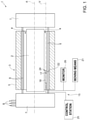
figure 1 is a diagrammatic side view, with sectional parts and parts removed for clarity, of an alternator and of a device for inspecting the alternator in a first operating position; -
figure 2 is a front diagrammatic view, with sectional parts and parts removed for clarity, of the device for inspecting the alternator infigure 1 ; -
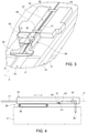
figure 3 is a perspective top view, with sectional parts and parts removed for clarity, of the inspection device shown infigure 1 ; -
figure 4 is a diagrammatic side view, with sectional parts and parts removed for clarity, of a detail offigure 1 ; -
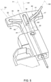
figure 5 is a perspective bottom view, with sectional parts and parts removed for clarity, of the inspection device shown infigure 1 . - With reference to
figure 1 ,numeral 1 indicates an alternator, as a whole, which extends along a longitudinal axis A and comprises arotor 2, which is the inductor and is the movable part ofturboalternator 1, and a stator 3, which is the armature and is the fixed part of the turboalternator. -
Rotor 2 is substantially cylindrical shaped and rotates - moved by a turbine (not illustrated) - about its own axis, which coincides with the longitudinal axis A ofalternator 1. - Stator 3 is a hollow cylinder which is coaxial with
rotor 2, which extends outsiderotor 2. The space comprised betweenrotor 2 and stator 3 is called air gap 4. - Stator 3 comprises a cylindrical core 5, which extends along the longitudinal axis A, a plurality of electrical windings 6 (only some of which are shown diagrammatically in
figure 1 ), two heads 7 arranged at the ends of stator 3 and of terminals 8 for drawing the current. The windings 6 are crossed by a current induced by the rotation ofrotor 2. - With reference to
figure 2 , the cylindrical core 5 has a plurality of axial grooves, calledslots 10, which extend for the entire length of the cylindrical core 5. Theslots 10 are separated and delimited bylongitudinal projections 11, which are parallel to axis A. - Each winding 6 comprises a plurality of
conductor bars 12, each of which is arranged in part along a defined path inside theslots 10, and in part at the heads 7 (figure 1 ). Each electrical winding 6 is therefore arranged inseveral slots 10. In particular, each winding 6 passes through afirst slot 10, comes out of thefirst slot 10 at a head 7 (figure 1 ) to then enter asecond slot 10 and comes out at the opposite head 7 (figure 1 ), enters athird slot 10 and so on, for a number of times defined in the project. - In particular, each
slot 10 accommodates two bars 12: a hollowexternal bar 12a and a hollowinternal bar 12b. -
Figures 1 and2 show adevice 15 for inspectingalternator 1 according to the present invention. - With particular reference to
figure 1 ,device 15 is arranged in the air gap 4 and is configured for inspecting stator 3 ofalternator 1 withrotor 2 assembled. -
Device 15 comprises acarriage 16, aprobe 17, first moving means 20 configured for movingprobe 17 along a moving axis V belonging to a moving plane (shown infigures 3 and 4 ), second moving means 21 (diagrammatically shown infigure 1 ) connected toprobe 17 and configured for moving afree end 22 ofprobe 17, at least a first driving element 24 (best shown infigures 3 and 4 ) shaped fordeflecting probe 17 along a first direction D1 transversal to the moving axis V on a first side of the moving plane, acontrol station 25 and amonitor 26 connected toprobe 17. - With reference to
figures 3 and 4 ,carriage 16 is arranged preferably resting on core 5 and is movable along a direction parallel to axis A. In the non-limiting embodiment herein described and illustrated,carriage 16 moves substantially along the moving axis V. - In detail,
carriage 16 is provided with a moving system 28 (partly shown infigure 4 ) which is controlled remotely by means of thecontrol station 25. - In the non-limiting embodiment herein described and illustrated, the moving
system 28 comprises an electric motor (not illustrated in the accompanying figures for simplicity), two tracks 30 (one of which is diagrammatically illustrated infigure 4 ) and drive means (not illustrated in the accompanying figures for simplicity) configured to transmit the motion of the electric motor to thetracks 30. - In use, each
track 30 is arranged resting on arespective projection 11 of core 5 of stator 3. - In the non-limiting embodiment herein described and illustrated, the
tracks 30 and/or the drive means are coupled to elements made of magnetic material so as to ensure a secure and reliable adhesion of thetracks 30 to therespective projections 11 of the entire core 5, including the upper portion of core 5. - Variants (not illustrated) provide for other elements of
carriage 16 to be made of magnetic material to ensure the adhesion betweencarriage 16 and theprojections 11 to whichcarriage 16 is to be coupled. - With reference to
figure 3 ,carriage 16 comprises twomain bodies 34, each of which is coupled to arespective track 30, ahead 35 and amiddle portion 36 arranged between the head and the twomain bodies 34. - The two
main bodies 34 are arranged side by side, extend parallel to one another and are coupled to each other by means of aconnection system 37. - In the non-limiting embodiment herein described and illustrated, the
connection system 37 is configured so that the distance between themain bodies 34 is adjustable. For example, theconnection system 37 comprises twotubular elements 38, telescopic tubular elements. - Due to the possibility of adjusting the distance between the
main bodies 34, the distance between the centers of thetracks 30 may be adjusted so that eachtrack 30 is coupled to therespective projection 11 of the cylindrical core 5 of stator 3. Thereby,device 15 according to the present invention may be engaged on alternators of different sizes in which the distance is variable between theprojections 11 of core 5. - It is understood that
carriage 16 may comprise a single main body coupled to thetracks 30 and that the distance between the centers of thetracks 30 is in any case adjustable. - The
middle portion 36 is preferably coupled to one of the twomain bodies 34 and supportsprobe 15 along the moving axis V. - Preferably, the
middle portion 36 comprises anaccommodating seat 40 configured for accommodating the first moving means 20 ofprobe 17. - With reference to
figure 4 , the first moving means 20 ofprobe 17 comprise an electric motor (not illustrated for simplicity), at least one roller 41 arranged againstprobe 17, and drive means for transmitting the motion of the motor to roller 41. - Roller 41 rotates with respect to an axis O which is orthogonal to the moving axis V of
probe 17. - Roller 41 may rotate in a first direction V1 to obtain a forward movement of
probe 17 along the moving axis V, and in a second direction V2 to obtain a reverse movement ofprobe 17 along the moving axis V. - The operation of the electric motor of the moving means 20 and the setting of the direction of rotation of roller 41 is automatically regulated by the
control station 25 or following a manual adjustment. - In use, the operation of the electric motor determines the advancing of
carriage 16 along the moving axis V. - The second moving means 21 are configured to move the
free end 22 ofprobe 17. - With reference to
figure 5 ,head 35 comprises amain conduit 43, thefirst driving element 24, which extends substantially along the moving axis V, asecond driving element 44 and athird driving element 45. Thesecond driving element 44 and thethird driving element 45 are arranged preferably symmetrical with respect to the moving axis V and extend along respective directions. - Similarly to the
first driving element 24, thesecond driving element 44 and thethird driving element 45 are shaped so as to deflectprobe 17 in a respective second direction D2 and in a respective third direction D3 on the first side of the moving plane. - The second direction D2 and the third direction D3 are both transversal to the moving axis V of
probe 17. - The
main conduit 43drives probe 17 along the moving axis V and is in communication with thefirst driving element 24, thesecond driving element 44 and thethird driving element 45 by means of respective inlet mouths. - In the non-limiting embodiment herein described and illustrated, the
first driving element 24, thesecond driving element 44 and thethird driving element 45 are defined byrespective grooves head 35. Eachgroove - Specifically, depth A1, A2, A3 of each
groove probe 17, which is determined by the rotation of roller 41 in direction V1. - In use, the
free end 22 ofprobe 17 is moved by the moving means 21 under the control of thecontrol station 25 so as to engage, according to the needs, one from thefirst driving element 24, thesecond driving element 44 and thethird driving element 45. - Preferably, the
control station 25 is provided with a manual control (not illustrated) (joystick) capable of controlling the movement ofend 22 ofprobe 17. - The movement of
probe 17 set by the rotation of roller 41 in direction V1 determines a forward movement ofprobe 17 inside therespective driving element probe 17 in the respective direction D1, D2 and D3. - The driving
elements probe 17 penetrates inside aslot 10 in different directions to completely inspectslot 10 and thebars 12 contained therein. - With reference to
figure 2 , thefirst driving element 24 determines a deflection ofprobe 17 in direction D1 in a first portion inside aslot 10, thesecond driving element 44 determines a deflection ofprobe 17 in direction D2 of a second portion insideslot 10, and thethird driving element 45 determines a deflection ofprobe 17 in direction D3 insideslot 10. Thereby,device 15 according to the present invention is capable of thoroughly inspecting eachslot 10. - Furthermore, with the
same device 15 it is possible to thoroughly inspect the surface of the bars positioned inside the slots adjacent to the slot being inspected, which is visible through the ventilation channels. - It is understood that the number of driving elements herein described and illustrated is purely indicative. A variant (not illustrated) provides for the driving elements to be greater than three so as to direct the probe, for example, onto further slots of core 5 of stator 3.
- A variant (not illustrated) contemplates for each driving
element control station 25. Thereby, the selective occlusion of two inlet mouths drivesprobe 17 toward the driving element with the inlet mouth not occluded. Such a variant allows the elimination of the second moving means 21 for moving thefree end 22. - Advantageously,
device 15 according to the present invention allows the complete inspection of thebars 12 that define the windings 6 inalternators 1 withrotor 2 assembled. Not only is it possible due to this aspect to inspect thebars 12 during scheduled maintenance operations, but also during extraordinary maintenance operations without requiring the disassembly of machine components which would excessively slow down the operability of the plant on whichalternator 1 is assembled. - Furthermore,
device 15 according to the present invention does not engage the ventilation channels of the stator and therefore does not require such channels to be emptied of the coolant contained therein, with apparent advantages in terms of intervention times and costs. - Finally,
device 15 according to the present invention is easy and affordable to make and allows ordinary inspection costs to be significantly reduced by avoiding the disassembly of the rotor. - Finally, it is apparent that modifications and variants may be made to the device and the method herein described without departing from the scope of the accompanying claims.
Claims (16)
- Device (15) for inspecting an alternator of a plant for electric energy production comprising:- a probe (17);- first moving means (20) configured for moving the probe (17) along a moving axis (V) lying on a moving plane;- at least a first driving element (24, 44, 45) shaped for deflecting the probe (17) in a first direction (D1, D2, D3) transversal to the moving axis (V) on a first side of the plane;the device being characterized in that, in use, the driving element (24, 44, 45) is arranged so that, once deflected, the probe (17) penetrates inside one slot (10) of the alternator.
- Device according to claim 1, comprising at least a second driving element (44, 45, 24) shaped for deflecting the probe (17) in a second direction (D2, D3, D1) transversal to the moving axis (V) on a first side of the plane.
- Device according to claim 2, comprising at least a third driving element (45, 24, 44) shaped for deflecting the probe (17) in a third direction (D3, D1, D2) transversal to the moving axis (V) on a first side of the plane.
- Device according to anyone of the foregoing claims, comprising a control station (25) configured to control the first moving means (20).
- Device according to claim 4, comprising second moving means (21) configured to move an end (22) of the probe (17) .
- Device according to claim 5, wherein the control station (25) is configured to control the second moving means (21) .
- Device according to any one of claims from 4 to 6, wherein the control station (25) comprises at least a first manual control configured to control the first moving means (20) .
- Device according to anyone of the foregoing claims, comprising at least an image detector and at least a monitor (26), coupled to the probe (17).
- Device according to anyone of the foregoing claims comprising a carriage (16) provided with a moving system (28); the carriage (16) being configured for supporting, at least in part, the probe (17) and the first driving element (24, 44, 45).
- Device according to claim 9, wherein the carriage (16) comprises at least an element made of magnetic material.
- Method for inspecting an alternator (1) of a plant for electric energy production comprising the steps of:arranging a probe (17) in an air gap (4) of the alternator (1);moving the probe (17) along a moving axis (V) lying on a moving plane;deflecting the probe (17) along a first direction (D1, D2, D3) transversal to the moving axis (V) on a first side of the plane;detecting images by means of the probe (17);the method being characterized in that the step of deflecting the probe (17) comprises deflecting the probe (17) so that, once deflected, the probe (17) penetrates inside one slot (10) of the alternator.
- Method according to claim 11, comprising the step of deflecting the probe (17) along a second direction (D2, D3, D1) transversal to the moving axis (V) on a first side of the plane.
- Method according to claim 12, comprising the step of deflecting the probe along a third direction (D3, D2, D1) transversal to the moving axis (V) on a first side of the plane.
- Method according to any one of claims from 11 to 13, comprising the step of moving an end (22) of the probe (17) .
- Method according to any one of claims from 11 to 14, wherein the step of arranging a probe (17) in an air gap (4) of the alternator (1) is performed without disassembling a rotor (2) of the alternator (1).
- Method according to any one of claims from 11 to 15, wherein the step of arranging a probe (17) in an air gap (4) of the alternator (1) is performed without disassembling heads (7) of the alternator (1).
Applications Claiming Priority (2)
| Application Number | Priority Date | Filing Date | Title |
|---|---|---|---|
| IT002223A ITMI20132223A1 (en) | 2013-12-31 | 2013-12-31 | DEVICE AND METHOD TO INSPECT AN ALTERNATOR |
| PCT/IB2014/067146 WO2015101894A1 (en) | 2013-12-31 | 2014-12-19 | Device and method for inspecting an alternator |
Publications (2)
| Publication Number | Publication Date |
|---|---|
| EP3090270A1 EP3090270A1 (en) | 2016-11-09 |
| EP3090270B1 true EP3090270B1 (en) | 2022-02-02 |
Family
ID=50336427
Family Applications (1)
| Application Number | Title | Priority Date | Filing Date |
|---|---|---|---|
| EP14833258.8A Active EP3090270B1 (en) | 2013-12-31 | 2014-12-19 | Device and method for inspecting an alternator |
Country Status (4)
| Country | Link |
|---|---|
| EP (1) | EP3090270B1 (en) |
| CN (1) | CN106062577B (en) |
| IT (1) | ITMI20132223A1 (en) |
| WO (1) | WO2015101894A1 (en) |
Families Citing this family (1)
| Publication number | Priority date | Publication date | Assignee | Title |
|---|---|---|---|---|
| CN115681009A (en) * | 2021-07-23 | 2023-02-03 | 上海勘测设计研究院有限公司 | A wind power station with flexible detection function |
Family Cites Families (6)
| Publication number | Priority date | Publication date | Assignee | Title |
|---|---|---|---|---|
| IN169952B (en) * | 1987-02-11 | 1992-01-18 | Westinghouse Electric Corp | |
| US5105658A (en) * | 1987-02-11 | 1992-04-21 | Westinghouse Electric Corp. | Electric generator inspection system and motor controller |
| IT1269818B (en) * | 1994-05-23 | 1997-04-15 | Ansaldo Gie Srl | EQUIPMENT AND DIAGNOSTIC PROCEDURE FOR MONITORING THE EFFICIENCY OF ROTATING ELECTRIC GENERATORS, SUCH AS TURBO ALTERNATORS |
| DE10107401A1 (en) * | 2001-02-14 | 2002-08-29 | Alstom Switzerland Ltd | Device for generator diagnosis with a built-in rotor |
| US7208971B2 (en) * | 2002-10-15 | 2007-04-24 | General Electric Company | Manual probe carriage system and method of using the same |
| EP2071343B1 (en) * | 2007-12-10 | 2013-10-16 | Alstom Technology Ltd | Self-guiding instrument carrier for in-situ operation in a generator |
-
2013
- 2013-12-31 IT IT002223A patent/ITMI20132223A1/en unknown
-
2014
- 2014-12-19 CN CN201480071753.XA patent/CN106062577B/en active Active
- 2014-12-19 WO PCT/IB2014/067146 patent/WO2015101894A1/en not_active Ceased
- 2014-12-19 EP EP14833258.8A patent/EP3090270B1/en active Active
Also Published As
| Publication number | Publication date |
|---|---|
| ITMI20132223A1 (en) | 2015-07-01 |
| CN106062577B (en) | 2018-12-11 |
| EP3090270A1 (en) | 2016-11-09 |
| CN106062577A (en) | 2016-10-26 |
| WO2015101894A1 (en) | 2015-07-09 |
Similar Documents
| Publication | Publication Date | Title |
|---|---|---|
| US11215046B2 (en) | Wellbore inspection system and method for ultra-deep vertical shaft | |
| JP5936270B2 (en) | Winding device and winding method | |
| US10689228B2 (en) | Elevator system evaluation device | |
| EP1233278B1 (en) | Device for diagnosing a generator with mounted rotor | |
| CN101965673A (en) | Apparatus and method for winding and terminating cores of dynamoelectric machines | |
| DE102006002552B4 (en) | Manual probe carrier system | |
| EP3221711B1 (en) | System and method for inspection of a generator stator core step iron region with the rotor in-situ | |
| WO2015101894A1 (en) | Device and method for inspecting an alternator | |
| EP2782221A1 (en) | Method for testing a rod-shaped coil of a rotor of a rotating electrical machine | |
| CN105084113A (en) | Automatic wire winding device | |
| CN103498843A (en) | Stretchable sleeve device and measuring and control method thereof | |
| CN103303735B (en) | A kind of wire harness automatic winder and method for winding thereof | |
| CN108792808B (en) | Automatic precise winding and arranging equipment and method | |
| WO2015169512A1 (en) | Method and apparatus for detecting interturn faults, and electrical machine | |
| CN104280220B (en) | A kind of optical detecting platform | |
| KR20250054060A (en) | Method for inspecting and verifying accurate stripping process of an insulating layer at predefined sections of a conductive wire covered by a dielectric material layer and associated assembly for inspection and verification | |
| CN103794356B (en) | Winder and method for winding | |
| CN114678819A (en) | Cable bundle test simultaneous injection test device | |
| CN108455387A (en) | A kind of captive balloon draw off gear | |
| CN209120010U (en) | A kind of precise wire arrangement coiling spindle unit | |
| Savenkov et al. | New robotic technologies for inspecting two pole electric generators while the rotor remains in place | |
| KR101259141B1 (en) | Docking apparatus and moving apparatus having the same and docking method for moving apparatus | |
| JP3672710B2 (en) | Winding device | |
| US20240418779A1 (en) | Test system | |
| CN223500780U (en) | A test device for disconnecting switch support |
Legal Events
| Date | Code | Title | Description |
|---|---|---|---|
| PUAI | Public reference made under article 153(3) epc to a published international application that has entered the european phase |
Free format text: ORIGINAL CODE: 0009012 |
|
| 17P | Request for examination filed |
Effective date: 20160620 |
|
| AK | Designated contracting states |
Kind code of ref document: A1 Designated state(s): AL AT BE BG CH CY CZ DE DK EE ES FI FR GB GR HR HU IE IS IT LI LT LU LV MC MK MT NL NO PL PT RO RS SE SI SK SM TR |
|
| AX | Request for extension of the european patent |
Extension state: BA ME |
|
| DAX | Request for extension of the european patent (deleted) | ||
| GRAP | Despatch of communication of intention to grant a patent |
Free format text: ORIGINAL CODE: EPIDOSNIGR1 |
|
| STAA | Information on the status of an ep patent application or granted ep patent |
Free format text: STATUS: GRANT OF PATENT IS INTENDED |
|
| INTG | Intention to grant announced |
Effective date: 20210728 |
|
| GRAS | Grant fee paid |
Free format text: ORIGINAL CODE: EPIDOSNIGR3 |
|
| GRAA | (expected) grant |
Free format text: ORIGINAL CODE: 0009210 |
|
| STAA | Information on the status of an ep patent application or granted ep patent |
Free format text: STATUS: THE PATENT HAS BEEN GRANTED |
|
| AK | Designated contracting states |
Kind code of ref document: B1 Designated state(s): AL AT BE BG CH CY CZ DE DK EE ES FI FR GB GR HR HU IE IS IT LI LT LU LV MC MK MT NL NO PL PT RO RS SE SI SK SM TR |
|
| REG | Reference to a national code |
Ref country code: GB Ref legal event code: FG4D |
|
| REG | Reference to a national code |
Ref country code: CH Ref legal event code: EP Ref country code: AT Ref legal event code: REF Ref document number: 1466718 Country of ref document: AT Kind code of ref document: T Effective date: 20220215 |
|
| REG | Reference to a national code |
Ref country code: DE Ref legal event code: R096 Ref document number: 602014082395 Country of ref document: DE |
|
| REG | Reference to a national code |
Ref country code: IE Ref legal event code: FG4D |
|
| REG | Reference to a national code |
Ref country code: LT Ref legal event code: MG9D |
|
| REG | Reference to a national code |
Ref country code: NL Ref legal event code: MP Effective date: 20220202 |
|
| REG | Reference to a national code |
Ref country code: AT Ref legal event code: MK05 Ref document number: 1466718 Country of ref document: AT Kind code of ref document: T Effective date: 20220202 |
|
| PG25 | Lapsed in a contracting state [announced via postgrant information from national office to epo] |
Ref country code: SE Free format text: LAPSE BECAUSE OF FAILURE TO SUBMIT A TRANSLATION OF THE DESCRIPTION OR TO PAY THE FEE WITHIN THE PRESCRIBED TIME-LIMIT Effective date: 20220202 Ref country code: RS Free format text: LAPSE BECAUSE OF FAILURE TO SUBMIT A TRANSLATION OF THE DESCRIPTION OR TO PAY THE FEE WITHIN THE PRESCRIBED TIME-LIMIT Effective date: 20220202 Ref country code: PT Free format text: LAPSE BECAUSE OF FAILURE TO SUBMIT A TRANSLATION OF THE DESCRIPTION OR TO PAY THE FEE WITHIN THE PRESCRIBED TIME-LIMIT Effective date: 20220602 Ref country code: NO Free format text: LAPSE BECAUSE OF FAILURE TO SUBMIT A TRANSLATION OF THE DESCRIPTION OR TO PAY THE FEE WITHIN THE PRESCRIBED TIME-LIMIT Effective date: 20220502 Ref country code: NL Free format text: LAPSE BECAUSE OF FAILURE TO SUBMIT A TRANSLATION OF THE DESCRIPTION OR TO PAY THE FEE WITHIN THE PRESCRIBED TIME-LIMIT Effective date: 20220202 Ref country code: LT Free format text: LAPSE BECAUSE OF FAILURE TO SUBMIT A TRANSLATION OF THE DESCRIPTION OR TO PAY THE FEE WITHIN THE PRESCRIBED TIME-LIMIT Effective date: 20220202 Ref country code: HR Free format text: LAPSE BECAUSE OF FAILURE TO SUBMIT A TRANSLATION OF THE DESCRIPTION OR TO PAY THE FEE WITHIN THE PRESCRIBED TIME-LIMIT Effective date: 20220202 Ref country code: ES Free format text: LAPSE BECAUSE OF FAILURE TO SUBMIT A TRANSLATION OF THE DESCRIPTION OR TO PAY THE FEE WITHIN THE PRESCRIBED TIME-LIMIT Effective date: 20220202 Ref country code: BG Free format text: LAPSE BECAUSE OF FAILURE TO SUBMIT A TRANSLATION OF THE DESCRIPTION OR TO PAY THE FEE WITHIN THE PRESCRIBED TIME-LIMIT Effective date: 20220502 |
|
| PG25 | Lapsed in a contracting state [announced via postgrant information from national office to epo] |
Ref country code: PL Free format text: LAPSE BECAUSE OF FAILURE TO SUBMIT A TRANSLATION OF THE DESCRIPTION OR TO PAY THE FEE WITHIN THE PRESCRIBED TIME-LIMIT Effective date: 20220202 Ref country code: LV Free format text: LAPSE BECAUSE OF FAILURE TO SUBMIT A TRANSLATION OF THE DESCRIPTION OR TO PAY THE FEE WITHIN THE PRESCRIBED TIME-LIMIT Effective date: 20220202 Ref country code: GR Free format text: LAPSE BECAUSE OF FAILURE TO SUBMIT A TRANSLATION OF THE DESCRIPTION OR TO PAY THE FEE WITHIN THE PRESCRIBED TIME-LIMIT Effective date: 20220503 Ref country code: FI Free format text: LAPSE BECAUSE OF FAILURE TO SUBMIT A TRANSLATION OF THE DESCRIPTION OR TO PAY THE FEE WITHIN THE PRESCRIBED TIME-LIMIT Effective date: 20220202 Ref country code: AT Free format text: LAPSE BECAUSE OF FAILURE TO SUBMIT A TRANSLATION OF THE DESCRIPTION OR TO PAY THE FEE WITHIN THE PRESCRIBED TIME-LIMIT Effective date: 20220202 |
|
| PG25 | Lapsed in a contracting state [announced via postgrant information from national office to epo] |
Ref country code: IS Free format text: LAPSE BECAUSE OF FAILURE TO SUBMIT A TRANSLATION OF THE DESCRIPTION OR TO PAY THE FEE WITHIN THE PRESCRIBED TIME-LIMIT Effective date: 20220602 |
|
| PG25 | Lapsed in a contracting state [announced via postgrant information from national office to epo] |
Ref country code: SM Free format text: LAPSE BECAUSE OF FAILURE TO SUBMIT A TRANSLATION OF THE DESCRIPTION OR TO PAY THE FEE WITHIN THE PRESCRIBED TIME-LIMIT Effective date: 20220202 Ref country code: SK Free format text: LAPSE BECAUSE OF FAILURE TO SUBMIT A TRANSLATION OF THE DESCRIPTION OR TO PAY THE FEE WITHIN THE PRESCRIBED TIME-LIMIT Effective date: 20220202 Ref country code: RO Free format text: LAPSE BECAUSE OF FAILURE TO SUBMIT A TRANSLATION OF THE DESCRIPTION OR TO PAY THE FEE WITHIN THE PRESCRIBED TIME-LIMIT Effective date: 20220202 Ref country code: EE Free format text: LAPSE BECAUSE OF FAILURE TO SUBMIT A TRANSLATION OF THE DESCRIPTION OR TO PAY THE FEE WITHIN THE PRESCRIBED TIME-LIMIT Effective date: 20220202 Ref country code: DK Free format text: LAPSE BECAUSE OF FAILURE TO SUBMIT A TRANSLATION OF THE DESCRIPTION OR TO PAY THE FEE WITHIN THE PRESCRIBED TIME-LIMIT Effective date: 20220202 Ref country code: CZ Free format text: LAPSE BECAUSE OF FAILURE TO SUBMIT A TRANSLATION OF THE DESCRIPTION OR TO PAY THE FEE WITHIN THE PRESCRIBED TIME-LIMIT Effective date: 20220202 |
|
| REG | Reference to a national code |
Ref country code: DE Ref legal event code: R097 Ref document number: 602014082395 Country of ref document: DE |
|
| PG25 | Lapsed in a contracting state [announced via postgrant information from national office to epo] |
Ref country code: AL Free format text: LAPSE BECAUSE OF FAILURE TO SUBMIT A TRANSLATION OF THE DESCRIPTION OR TO PAY THE FEE WITHIN THE PRESCRIBED TIME-LIMIT Effective date: 20220202 |
|
| PLBE | No opposition filed within time limit |
Free format text: ORIGINAL CODE: 0009261 |
|
| STAA | Information on the status of an ep patent application or granted ep patent |
Free format text: STATUS: NO OPPOSITION FILED WITHIN TIME LIMIT |
|
| 26N | No opposition filed |
Effective date: 20221103 |
|
| PG25 | Lapsed in a contracting state [announced via postgrant information from national office to epo] |
Ref country code: SI Free format text: LAPSE BECAUSE OF FAILURE TO SUBMIT A TRANSLATION OF THE DESCRIPTION OR TO PAY THE FEE WITHIN THE PRESCRIBED TIME-LIMIT Effective date: 20220202 |
|
| PG25 | Lapsed in a contracting state [announced via postgrant information from national office to epo] |
Ref country code: IT Free format text: LAPSE BECAUSE OF FAILURE TO SUBMIT A TRANSLATION OF THE DESCRIPTION OR TO PAY THE FEE WITHIN THE PRESCRIBED TIME-LIMIT Effective date: 20220202 |
|
| REG | Reference to a national code |
Ref country code: CH Ref legal event code: PL |
|
| GBPC | Gb: european patent ceased through non-payment of renewal fee |
Effective date: 20221219 |
|
| REG | Reference to a national code |
Ref country code: BE Ref legal event code: MM Effective date: 20221231 |
|
| PG25 | Lapsed in a contracting state [announced via postgrant information from national office to epo] |
Ref country code: LU Free format text: LAPSE BECAUSE OF NON-PAYMENT OF DUE FEES Effective date: 20221219 |
|
| PG25 | Lapsed in a contracting state [announced via postgrant information from national office to epo] |
Ref country code: LI Free format text: LAPSE BECAUSE OF NON-PAYMENT OF DUE FEES Effective date: 20221231 Ref country code: IE Free format text: LAPSE BECAUSE OF NON-PAYMENT OF DUE FEES Effective date: 20221219 Ref country code: GB Free format text: LAPSE BECAUSE OF NON-PAYMENT OF DUE FEES Effective date: 20221219 Ref country code: CH Free format text: LAPSE BECAUSE OF NON-PAYMENT OF DUE FEES Effective date: 20221231 |
|
| PG25 | Lapsed in a contracting state [announced via postgrant information from national office to epo] |
Ref country code: FR Free format text: LAPSE BECAUSE OF NON-PAYMENT OF DUE FEES Effective date: 20221231 Ref country code: BE Free format text: LAPSE BECAUSE OF NON-PAYMENT OF DUE FEES Effective date: 20221231 |
|
| PG25 | Lapsed in a contracting state [announced via postgrant information from national office to epo] |
Ref country code: HU Free format text: LAPSE BECAUSE OF FAILURE TO SUBMIT A TRANSLATION OF THE DESCRIPTION OR TO PAY THE FEE WITHIN THE PRESCRIBED TIME-LIMIT; INVALID AB INITIO Effective date: 20141219 |
|
| PG25 | Lapsed in a contracting state [announced via postgrant information from national office to epo] |
Ref country code: CY Free format text: LAPSE BECAUSE OF FAILURE TO SUBMIT A TRANSLATION OF THE DESCRIPTION OR TO PAY THE FEE WITHIN THE PRESCRIBED TIME-LIMIT Effective date: 20220202 |
|
| PG25 | Lapsed in a contracting state [announced via postgrant information from national office to epo] |
Ref country code: MK Free format text: LAPSE BECAUSE OF FAILURE TO SUBMIT A TRANSLATION OF THE DESCRIPTION OR TO PAY THE FEE WITHIN THE PRESCRIBED TIME-LIMIT Effective date: 20220202 |
|
| P01 | Opt-out of the competence of the unified patent court (upc) registered |
Effective date: 20240430 |
|
| PG25 | Lapsed in a contracting state [announced via postgrant information from national office to epo] |
Ref country code: MC Free format text: LAPSE BECAUSE OF FAILURE TO SUBMIT A TRANSLATION OF THE DESCRIPTION OR TO PAY THE FEE WITHIN THE PRESCRIBED TIME-LIMIT Effective date: 20220202 |
|
| PG25 | Lapsed in a contracting state [announced via postgrant information from national office to epo] |
Ref country code: MC Free format text: LAPSE BECAUSE OF FAILURE TO SUBMIT A TRANSLATION OF THE DESCRIPTION OR TO PAY THE FEE WITHIN THE PRESCRIBED TIME-LIMIT Effective date: 20220202 |
|
| PG25 | Lapsed in a contracting state [announced via postgrant information from national office to epo] |
Ref country code: MT Free format text: LAPSE BECAUSE OF FAILURE TO SUBMIT A TRANSLATION OF THE DESCRIPTION OR TO PAY THE FEE WITHIN THE PRESCRIBED TIME-LIMIT Effective date: 20220202 |
|
| PG25 | Lapsed in a contracting state [announced via postgrant information from national office to epo] |
Ref country code: TR Free format text: LAPSE BECAUSE OF FAILURE TO SUBMIT A TRANSLATION OF THE DESCRIPTION OR TO PAY THE FEE WITHIN THE PRESCRIBED TIME-LIMIT Effective date: 20220202 |
|
| PGFP | Annual fee paid to national office [announced via postgrant information from national office to epo] |
Ref country code: DE Payment date: 20251222 Year of fee payment: 12 |