EP3090121B1 - Drill rod handling system for moving drill rods to and from an operative position - Google Patents
Drill rod handling system for moving drill rods to and from an operative position Download PDFInfo
- Publication number
- EP3090121B1 EP3090121B1 EP14876854.2A EP14876854A EP3090121B1 EP 3090121 B1 EP3090121 B1 EP 3090121B1 EP 14876854 A EP14876854 A EP 14876854A EP 3090121 B1 EP3090121 B1 EP 3090121B1
- Authority
- EP
- European Patent Office
- Prior art keywords
- drill
- cradle
- relative
- longitudinal axis
- rod
- Prior art date
- Legal status (The legal status is an assumption and is not a legal conclusion. Google has not performed a legal analysis and makes no representation as to the accuracy of the status listed.)
- Active
Links
- 238000013519 translation Methods 0.000 claims description 54
- 238000005553 drilling Methods 0.000 claims description 22
- 238000000034 method Methods 0.000 claims description 21
- 238000004891 communication Methods 0.000 claims description 19
- 230000000694 effects Effects 0.000 claims description 18
- 230000004913 activation Effects 0.000 claims description 6
- 230000000712 assembly Effects 0.000 description 27
- 238000000429 assembly Methods 0.000 description 27
- 230000008878 coupling Effects 0.000 description 9
- 238000010168 coupling process Methods 0.000 description 9
- 238000005859 coupling reaction Methods 0.000 description 9
- 230000015572 biosynthetic process Effects 0.000 description 6
- JOYRKODLDBILNP-UHFFFAOYSA-N Ethyl urethane Chemical compound CCOC(N)=O JOYRKODLDBILNP-UHFFFAOYSA-N 0.000 description 4
- 230000009471 action Effects 0.000 description 4
- 150000001247 metal acetylides Chemical class 0.000 description 4
- 125000006850 spacer group Chemical group 0.000 description 4
- 230000008901 benefit Effects 0.000 description 3
- 230000006378 damage Effects 0.000 description 3
- 230000004323 axial length Effects 0.000 description 2
- JCXJVPUVTGWSNB-UHFFFAOYSA-N Nitrogen dioxide Chemical class O=[N]=O JCXJVPUVTGWSNB-UHFFFAOYSA-N 0.000 description 1
- 230000006978 adaptation Effects 0.000 description 1
- 238000013459 approach Methods 0.000 description 1
- 230000009286 beneficial effect Effects 0.000 description 1
- 230000000295 complement effect Effects 0.000 description 1
- 230000001419 dependent effect Effects 0.000 description 1
- 238000003780 insertion Methods 0.000 description 1
- 230000037431 insertion Effects 0.000 description 1
- 238000012986 modification Methods 0.000 description 1
- 230000004048 modification Effects 0.000 description 1
- 230000008569 process Effects 0.000 description 1
- 230000009467 reduction Effects 0.000 description 1
Images


Classifications
-
- E—FIXED CONSTRUCTIONS
- E21—EARTH DRILLING; MINING
- E21B—EARTH DRILLING, e.g. DEEP DRILLING; OBTAINING OIL, GAS, WATER, SOLUBLE OR MELTABLE MATERIALS OR A SLURRY OF MINERALS FROM WELLS
- E21B19/00—Handling rods, casings, tubes or the like outside the borehole, e.g. in the derrick; Apparatus for feeding the rods or cables
- E21B19/14—Racks, ramps, troughs or bins, for holding the lengths of rod singly or connected; Handling between storage place and borehole
- E21B19/15—Racking of rods in horizontal position; Handling between horizontal and vertical position
- E21B19/155—Handling between horizontal and vertical position
-
- E—FIXED CONSTRUCTIONS
- E21—EARTH DRILLING; MINING
- E21B—EARTH DRILLING, e.g. DEEP DRILLING; OBTAINING OIL, GAS, WATER, SOLUBLE OR MELTABLE MATERIALS OR A SLURRY OF MINERALS FROM WELLS
- E21B15/00—Supports for the drilling machine, e.g. derricks or masts
-
- E—FIXED CONSTRUCTIONS
- E21—EARTH DRILLING; MINING
- E21B—EARTH DRILLING, e.g. DEEP DRILLING; OBTAINING OIL, GAS, WATER, SOLUBLE OR MELTABLE MATERIALS OR A SLURRY OF MINERALS FROM WELLS
- E21B19/00—Handling rods, casings, tubes or the like outside the borehole, e.g. in the derrick; Apparatus for feeding the rods or cables
- E21B19/02—Rod or cable suspensions
- E21B19/06—Elevators, i.e. rod- or tube-gripping devices
-
- E—FIXED CONSTRUCTIONS
- E21—EARTH DRILLING; MINING
- E21B—EARTH DRILLING, e.g. DEEP DRILLING; OBTAINING OIL, GAS, WATER, SOLUBLE OR MELTABLE MATERIALS OR A SLURRY OF MINERALS FROM WELLS
- E21B19/00—Handling rods, casings, tubes or the like outside the borehole, e.g. in the derrick; Apparatus for feeding the rods or cables
- E21B19/20—Combined feeding from rack and connecting, e.g. automatically
-
- E—FIXED CONSTRUCTIONS
- E21—EARTH DRILLING; MINING
- E21B—EARTH DRILLING, e.g. DEEP DRILLING; OBTAINING OIL, GAS, WATER, SOLUBLE OR MELTABLE MATERIALS OR A SLURRY OF MINERALS FROM WELLS
- E21B19/00—Handling rods, casings, tubes or the like outside the borehole, e.g. in the derrick; Apparatus for feeding the rods or cables
- E21B19/24—Guiding or centralising devices for drilling rods or pipes
-
- E—FIXED CONSTRUCTIONS
- E21—EARTH DRILLING; MINING
- E21B—EARTH DRILLING, e.g. DEEP DRILLING; OBTAINING OIL, GAS, WATER, SOLUBLE OR MELTABLE MATERIALS OR A SLURRY OF MINERALS FROM WELLS
- E21B3/00—Rotary drilling
Definitions
- This invention relates to drill head assemblies for securing a drill rod in an operative position for drilling and rod handling operations. This invention further relates to loading devices for engaging a drill rod as it is secured to a drill head assembly.
- a drill rod Prior to drilling operations, a drill rod must be secured in the chuck of a drill head assembly.
- workers use their hands to support, lift, and/or rotate a drill rod in a position that allows the chuck to threadingly engage the drill rod.
- a worker threads a mainline hoist plug onto a new rod.
- the worker guides an end of the new rod over a previous rod in the hole, and the chuck is rotated by hand to engage the threads of the drill rod.
- the chuck is then repositioned and rotated to apply sufficient torque to the rod to make the joint.
- the workers will stabilize the drill rod such that the drill rod does not rotate with the chuck but is advanced axially within the chuck.
- the workers supporting the drill rod often fail to prevent rotation of the drill rod, and the workers also regularly fail to maintain the drill rod in alignment with the chuck.
- Some conventional attempts at addressing these problems include floating devices, such as spline/spring assemblies, and hydraulic float devices, such as feed cylinder valves. Both of these attempts allow axial translation during rotation.
- floating devices such as spline/spring assemblies
- hydraulic float devices such as feed cylinder valves. Both of these attempts allow axial translation during rotation.
- splined floating devices are expensive and heavy and can add to the overall length of the drill head assembly. It is not always practical to apply the force required to compress the springs of these floating devices before threading and/or unthreading the joint.
- the drill rod is not always oriented parallel to the feed cylinder, use of hydraulic float devices is not always possible.
- US 4,890,681 A discloses a method and apparatus for rotary power driven swivel drilling in which a rotary drive swivel unit is tilted for alignment with a horizontally approaching drill pipe, receives the horizontal drill pipe and makes up a joint with the output shaft, is reoriented under the weight of the drill pipe suspended therefrom such that it is in alignment over the drill string, and thereafter the drill pipe is added to the drill string.
- Described herein is a drill head assembly for securing a drill rod in an operative position, as defined in claim 1.
- Preferred and optional features are set out in dependent claims 2 to 7.
- a drilling method is also defined in claim 8.
- Ranges can be expressed herein as from “about” one particular value, and/or to "about” another particular value. When such a range is expressed, another aspect includes from the one particular value and/or to the other particular value. Similarly, when values are expressed as approximations, by use of the antecedent "about,” it will be understood that the particular value forms another aspect. It will be further understood that the endpoints of each of the ranges are significant both in relation to the other endpoint, and independently of the other endpoint.
- the terms "optional” or “optionally” mean that the subsequently described event or circumstance may or may not occur, and that the description includes instances where said event or circumstance occurs and instances where it does not.
- a drill rod handling system 150 for positioning a drill rod 12 in an operative position.
- the drill rod handling system 150 can comprise a loading device 70, 170, 370, a drill mast 16, and a drill head assembly 10 according to the invention.
- the drill mast 16 and the drill rod 12 can have respective longitudinal axes 18, 14.
- the drill rod handling system 150 can substantially eliminate the need for direct contact between an operator of the drill rod handling system and a drill rod to be loaded or unloaded from the drill head assembly 10. It is further contemplated that the drill rod handling system 150 can operate as fast as current drill loading and unloading methods while offering a cost reduction.
- the drill head assembly 10 is for use in securing the drill rod 12 in the operative position.
- the drill head assembly 10 is operatively coupled to the drill mast 16.
- the drill head assembly 10 can comprise a motor and a gear box as are known in the art.
- the disclosed drill head assembly 10 can be retrofit and/or added to an existing drilling system, such as, for example and without limitation, the LFTM 90D Surface Coring Drill system manufactured by BOART LONGYEAR (South Jordan, Utah).
- the drill head assembly 10 comprises a cradle 20, a chuck 30 operatively supported by the cradle, and can comprise a gear box portion 36.
- the cradle 20 is operatively configured for movement relative to both the longitudinal axis 18 of the drill mast 16and a transverse axis 19 substantially perpendicular to the longitudinal axis 18 of the drill mast 16.
- the chuck can be a NITRO CHUCKTM (BOART LONGYEAR, South Jordan, Utah) chuck.
- the chuck 30 can be any conventional chuck that is configured to grip drill shafts and spin with a head spindle as is known in the art.
- the chuck 30 has a longitudinal axis 32 and defines an opening 34.
- the opening 34 of the chuck 30 can be configured to securely receive a portion of a Kelly rod as is known in the art. It is contemplated that the Kelly rod can be configured for engagement with a portion of the drill rod 12 such that the longitudinal axis 14 of the drill rod 12 is substantially axially aligned with the longitudinal axis 32 of the chuck 30.
- the drill rod 12 can be positioned within the chuck 30 without the need of a Kelly rod as is known in the art.
- the drill head assembly 10 can comprise a head spindle 35 that spans between the gear box portion 36 and the chuck portion 30 of the drill head assembly 10.
- a drill rod receiving assembly 500 for receiving the drill rod 12 can be provided.
- the drill rod receiving assembly 500 can have a longitudinal axis 502 and be configured for positioning within the head spindle 35 of the drill head 10 such that the longitudinal axis of the drill rod receiving assembly is substantially aligned with a longitudinal axis of the head spindle.
- the drill rod receiving assembly 500 can comprise an elongate shaft 510 having a first end 512, an opposed second end 514, an inner surface 516, and an outer surface 518.
- the inner surface 516 of the elongate shaft 510 can define a bore 520 extending between the first and second ends 512, 514 of the elongate shaft 510.
- the first end 512 of the elongate shaft 510 can define a first opening 522 in communication with the bore 520.
- the second end 514 of the elongate shaft 510 can be configured for receipt within the chuck portion 30 of the drill head 10.
- the drill rod receiving assembly 500 can comprise a receiving element 530 configured for operative coupling to the gear box portion 36 of the drill head 10.
- the receiving element 530 can have a first end 532, an opposed second end 534, an inner surface 536, and an outer surface 538.
- the inner surface 536 of the receiving element 530 can define a bore 540 extending between the first and second ends 532, 534 of the receiving element.
- the first end 532 of the receiving element 530 can define a first opening 542 in communication with the bore 540.
- the second end 534 of the receiving element 530 can define a second opening 544 in communication with the bore 540.
- At least a portion of the inner surface 536 of the receiving element 530 can be inwardly tapered moving from the first opening 542 toward the second opening 544. At least a portion of the inner surface 536 of the receiving element 530 can be angled relative to the longitudinal axis 502 of the drill rod receiving assembly 500 at an angle ranging from about 10 degrees to about 45 degrees and, more preferably, about 15 degrees. Thus, the inner surface 536 of the receiving element 530 can be configured to provide between about 20 and about 90 degrees of tolerance during insertion of the drill rod 12 into the first opening 542 of the receiving element 530.
- this tolerance can permit receipt of a wide range of drill rods that are not axially aligned with the first opening 542 of the receiving element 530. It is further contemplated that the second end 534 of the receiving element 530 can be operatively coupled to the first end 512 of the elongate shaft 510 such that the second opening 544 of the receiving element 530 is substantially aligned and in communication with the first opening 522 of the elongate shaft.
- the inner surfaces 536, 516 of the receiving element and the elongate shaft can be configured to cooperate to guide the drill rod to a desired orientation in which a longitudinal axis of the drill rod 12 is substantially parallel to the longitudinal axis of the head spindle. It is contemplated that the longitudinal axis of the drill rod 12 can also be substantially parallel to (or in alignment with) the translation axis 15 of a loading device as further disclosed herein.
- the disclosed drill rod receiving assembly 500 can receive a drill rod in the desired orientation without the need for threading joints to pass the drill rod to a drilling assembly. During use of the disclosed drill rod receiving assembly 500, only axial advancement (i.e., pushing) of the drill rod is needed to correctly position the drill rod within the assembly 500.
- the drill rod receiving assembly 500 can further comprise a plate assembly 550.
- the plate assembly 550 can comprise a first plate 552 configured for circumferential engagement with the outer surface of the head spindle 35 of the drill head 10 and a second plate 554 configured to circumferentially engage a portion of the outer surface 538 of the receiving element 530 proximate the second end 534 of the receiving element.
- the plate assembly 550 can further comprise means for securely coupling the first plate 552 to the second plate 554 to thereby stabilize the receiving element.
- the means for securely coupling the first plate to the second plate can comprise at least one fastener configured to securely couple the first plate 552 to the second plate 554. It is contemplated that the at least one fastener can comprise a plurality of fasteners.
- each fastener of the at least one fastener can comprise any conventional fastener as is known in the art, including, for example and without limitation, a bolt, a screw, a pin, and the like.
- the means for securely coupling the first plate to the second plate can comprise a snap ring as is known in the art.
- the snap ring can be configured for operative engagement with an inner portion of the second plate 554 such that the snap ring is positioned between the second plate and the outer surface 538 of the receiving element 530.
- the drill rod receiving assembly 500 can further comprise a plurality of spacers 560.
- Each spacer 560 of the plurality of spacers can be configured to circumferentially surround a portion of the outer surface 518 of the elongate shaft 510 and to maintain the spacing between the outer surface of the elongate shaft and an inner surface of the head spindle.
- At least a portion of the inner surface 516 of the elongate shaft 510 can be configured for engagement with a portion of the drill rod 12 to support the drill rod in alignment with the longitudinal axis 502 of the receiving assembly 500 (and, thus, with the longitudinal axis of the chuck 30).
- a drill rod 12 can be inserted into the first opening 542 of the receiving element 530 and then advanced relative to the longitudinal axis 502 of the receiving assembly 500 such that the drill rod is received in the second opening 544 of the receiving element and then axially advanced through the first opening 522 of the elongate shaft 510 until the drill rod passes through the second opening 524 of the elongate shaft.
- the inwardly tapered profile of the receiving element 530 can accommodate receipt of drill rods positioned at a wide range of angles and then help establish alignment of the drill rod with the longitudinal axis 502 of the receiving assembly 500 as the drill rods are advanced toward the second opening 524 of the elongate shaft. It is further contemplated that the inwardly tapered profile of the receiving element 530 can be useful in a variety of operating conditions, including, for example and without limitation, when deflection occurs during feeding of a drill head down over a drill rod positioned within a foot clamp or during the addition of a drill rod onto a spindle. It is contemplated that the receiving element 530 and the elongate shaft 510 can be configured to prevent contact between the drill rod 12 and the chuck 30 until the drill rod is adequately positioned within the jaws of the chuck.
- the elongate shaft 510 can have a substantially constant inner diameter (defined by inner surface 516) and a substantially constant outer diameter (defined by outer surface 518).
- the receiving element 530 of the receiving assembly 500 can be selectively detachable from the head spindle 35 and the elongate shaft 510 of the receiving assembly. It is further contemplated that each elongate shaft 510 can be selectively removed from the drill head 10. It is contemplated that each respective receiving element 530 can be configured for operative connection to a corresponding elongate shaft 510. Thus, it is contemplated that, for a given drill rod 12, a suitably sized elongate shaft 510 and corresponding receiving element 530 can be selected for usage with the drill head 10 to permit advancement of the drill rod as disclosed herein.
- Figures 13A-13D depict various drill rods being advanced within suitably sized elongate shafts and their complementary receiving elements.
- the inner diameter of the elongate shaft 510 and at least a minimum inner diameter of the receiving element 530 increase, whereas the dimensions of the spacers 560 (which may not be used depending upon the diameter of the drill rod) decrease.
- the cradle 20 is configured for movement between a first position and a second position. As shown in Figures 8A-8B , in the first position, it is contemplated that the longitudinal axis 32 of the chuck 30 is substantially parallel to the longitudinal axis 18 of the drill mast 16. From the first position, the cradle 20 is configured for sequential axial and then pivotal (or, alternatively, sequential pivotal and then axial) movement relative to the transverse axis 19 to reach the second position. As shown in Figure 8C , in the second position, it is contemplated that the longitudinal axis 32 of the chuck 30 is substantially perpendicular to the longitudinal axis 18 of the drill mast 16.
- the cradle 20 in the second position, can be axially spaced from the drill mast 16 relative to the transverse axis 19. From the second position, the cradle 20 can be configured for sequential pivotal and then axial (or, alternatively, sequential axial and then pivotal) movement relative to the transverse axis 19 to return to the first position.
- the cradle 20 depending on the length of the drill rod, it will be appreciated that it may be necessary to lift the cradle 20 axially relative to the longitudinal axis 18 of the drill mast 16 before the cradle is sequentially pivotally and then axially moved relative to the transverse axis 19.
- pivotal movement of the cradle is restricted until the completion of axial movement relative to the transverse axis 19. It is further contemplated that axial movement of the cradle 20 relative to the transverse axis 19 can be restricted until the completion of pivotal movement of the cradle relative to the transverse axis.
- the cradle 20 (and, thus, the chuck 30) will not axially shift during tilting of the cradle relative to the transverse axis 19, such as, for example, while it is tilting during movement of the cradle from the second position to the first position.
- the cradle 20 (and, thus, the chuck 30) will not tilt while the cradle is shifting axially relative to the transverse axis 19, such as, for example, while it is shifting axially from the first position to the second position. It is contemplated that, by requiring a full axial shift before tilting occurs and/or a full tilt before axial shifting occurs, many of the safety risks associated with conventional drill head assemblies can be avoided.
- the drill head assembly 10 comprises a plurality of sensors 40. At least one sensor 40 of the plurality of sensors is configured to detect the completion of axial movement of the cradle 20 relative to the transverse axis 19. It is contemplated that at least one sensor 40 of the plurality of sensors is configured to detect the completion of pivotal movement of the cradle 20 relative to the transverse axis 19.
- the plurality of sensors 40 can comprise a plurality of proximity switches operatively coupled in a relay configuration.
- any conventional position sensors such as, for example and without limitation, electrical position sensors, programmable logic controllers (PLC's), and the like, can be used.
- the plurality of sensors 40 can optionally comprise a plurality of hydraulic sequence valves.
- the drill head assembly 10 can further comprise a first hydraulic cylinder 50 operatively coupled to the cradle and positioned in communication with the plurality of hydraulic sequence valves. It is contemplated that the first hydraulic cylinder 50 can optionally have a longitudinal axis substantially parallel to the transverse axis. It is further contemplated that activation of the first hydraulic cylinder 50 can be configured to effect axial movement of the cradle 20 relative to the transverse axis 19.
- the drill head assembly 10 can further comprise a second hydraulic cylinder 52 operatively coupled to the cradle 20 and positioned in communication with the plurality of hydraulic sequence valves.
- activation of the second hydraulic cylinder 52 can be configured to effect pivotal movement of the cradle 20 relative to the transverse axis 19.
- oil can be diverted between the first and second hydraulic cylinders 50, 52 as necessary to effect tilting and shifting of the cradle 20 and chuck 30.
- the plurality of sensors 40 and the first and second hydraulic cylinders 50, 52 can be positioned in operative communication with a control assembly 120 as further described herein.
- a control assembly 120 sequential axial and then pivotal movement of the cradle from the first position to the second position can be effected by a single action by an operator of the control assembly 120.
- sequential pivotal and then axial movement of the cradle from the second position to the first position can be effected by a single action by an operator of the control assembly.
- control assembly 120 can comprise a first lever (or other user input means) that can be activated to effect movement of the cradle from the first position to the second position as disclosed herein and a second lever (or other user input means) that can be activated to effect movement of the cradle from the second position to the first position as disclosed herein.
- movement about and between the first and second positions can be accomplished using a single lever (or other user input means) having two or more operative positions, with one operative position effecting movement from the first position to the second position and a second operative position effecting movement from the second position to the first position.
- control assembly 120 can comprise one or more additional user input means for effecting movement of the cradle relative to the longitudinal axis 18 of the drill mast 16.
- control assembly 120 can communicate with the plurality of sensors 40 and the hydraulic cylinders 50, 52 to ensure that axial movement of the cradle relative to the transverse axis is completed before pivotal movement begins and that pivotal movement of the cradle relative to the transverse axis is completed before axial movement relative to the transverse axis begins.
- the control assembly 120 can directs the plurality of sensors to move the cradle from the first position to the second position, the control assembly can actuate the first hydraulic cylinder to effect axial movement of the cradle relative to the transverse axis.
- the sensor and/or the control assembly can effect sequential actuation of the second hydraulic cylinder (e.g., in a relay configuration) to thereby effect pivotal movement of the cradle relative to the transverse axis; however, the control assembly cooperates with the plurality of sensors to prevent pivotal movement of the cradle until axial movement has been completed.
- a sensor of the plurality of sensors can also determine when pivotal movement of the cradle has been completed, thereby confirming positioning of the cradle in the second position.
- the control assembly 120 when the control assembly 120 directs the plurality of sensors to move the cradle from the second position to the first position, the control assembly can actuate the second hydraulic cylinder to effect pivotal movement of the cradle relative to the transverse axis.
- the sensor and/or the control assembly can effect sequential actuation of the first hydraulic cylinder (e.g., in a relay configuration) to thereby effect axial movement of the cradle relative to the transverse axis; however, the control assembly cooperates with the plurality of sensors to prevent axial movement of the cradle until pivotal movement has been completed.
- a sensor of the plurality of sensors can also determine when axial movement of the cradle has been completed, thereby confirming positioning of the cradle has been returned to the first position.
- the drill head assembly 10 can further comprise a plurality of spaced guide bars 60 operatively coupled to the cradle 20.
- Each guide bar 60 of the plurality of guide bars can have a longitudinal axis substantially parallel to the transverse axis 19. It is contemplated that the cradle 20 can be configured for movement along the plurality of guide bars 60 relative to the transverse axis 19. It is further contemplated that the plurality of guide bars 60 can be configured to support the cradle 20 during axial and pivotal movement of the cradle relative to the transverse axis 19. During or following tilting of the cradle 20, it is contemplated that the plurality of spaced guide bars 60 must fully support the cradle 20 before the drill head assembly 10 will be permitted to axially shift relative to the transverse axis 19.
- the loading device 70 can be used for engaging a drill rod 12 moving relative to a translation axis 15.
- the loading device 70 can optionally comprise a base assembly 80, a support assembly 90, and a clamping assembly 100.
- the base assembly 80 of the loading device 70 can comprise at least one horizontal roller. It is contemplated that the at least one horizontal roller can comprise a single horizontal roller. Optionally, the at least one horizontal roller can comprise at least one proximal roller 82 and at least one distal roller 86. The at least one proximal roller 82 can be spaced from the at least one distal roller 86. It is contemplated that the proximal and distal rollers 82, 86 can have respective longitudinal axes 84, 88. It is further contemplated that the longitudinal axes 84 of the at least one proximal roller 82 can be substantially parallel to the longitudinal axes 88 of the at least one distal roller 86. It is still further contemplated that the longitudinal axes 84, 88 of the proximal and distal rollers 82, 86 can be substantially perpendicular to the translation axis 15.
- the support assembly 90 of the loading device 70 can be secured to the base assembly 80.
- the support assembly 90 can comprise at least one support roller 92.
- the at least one support roller 92 can comprise a plurality of support rollers. It is contemplated that each support roller 92 of the at least one support roller can have a respective longitudinal axis 94. It is further contemplated that the longitudinal axes 94 of the at least one support roller 92 can be substantially parallel. It is still further contemplated that the longitudinal axes 94 of the at least one support roller 92 can be substantially perpendicular to the translation axis 15 and the longitudinal axes 84, 88 of the proximal and distal rollers 82, 86.
- the clamping assembly 100 of the loading device 70 can be spaced from the support assembly 90 relative to a transverse axis 72.
- the transverse axis 72 can optionally be substantially parallel to the longitudinal axes 84, 88 of the proximal and distal rollers 82, 86.
- the clamping assembly 100 can have at least one clamping roller 102 configured for movement relative to the transverse axis 72 between an open position and an engaged position.
- the at least one clamping roller 102 can have a longitudinal axis 104 that is substantially parallel to the longitudinal axes 94 of the at least one support roller 92.
- the at least one clamping roller 102 can comprise a plurality of clamping rollers.
- each clamping roller 102 can comprise a flexible material that is configured to also provide a surface for frictional engagement with a drill rod.
- the clamping roller 102 can comprise urethane.
- the clamping roller 102 can comprise carbides that are configured to frictionally engage a drill rod while minimizing damage to the drill rod.
- the clamping roller 102 can comprise urethane and carbides.
- the horizontal, support, and clamping rollers 82, 86, 92, 102 can cooperate to define a receiving space 74.
- the receiving space 74 can be configured to receive at least a portion of the drill rod 12. It is contemplated that, in the engaged position of the clamping roller 102, the horizontal, support, and clamping rollers 82, 86, 92, 102 can be positioned in engagement with the drill rod 12. It is further contemplated that, in the engaged position of the at least one clamping roller 102, the horizontal, support, and clamping rollers 82, 86, 92, 102 can be configured to permit axial movement of the drill rod 12 relative to the translation axis 15 but restrict rotation of the drill rod relative to the translation axis.
- the loading device 70 can further comprise a lever 112.
- the lever 112 can have a lever support 114 secured to the base assembly 80 and a coupling element 116 coupled to the lever 112 and the at least one clamping roller 102.
- the coupling element 116 can be pivotally coupled to the lever support 114.
- the coupling element 116 can be configured for pivotal movement relative to the lever support 114.
- selective pivotal movement of the coupling element 116 can effect movement of the clamping roller 102 relative to the transverse axis 72.
- the position of at least one of the lever support 114 and the support assembly 90 can be selectively adjustable relative to the transverse axis 72.
- the loading device 70 can comprise means for driving the lever 112.
- the means for driving the lever 112 can be configured to selectively move the lever, thereby effecting movement of the coupling element 116 and/or the clamping roller 102.
- the loading device 70 can comprise means for driving the at least one support roller 92.
- the means for driving the at least one support roller 92 can be configured to selectively rotate the at least one support roller.
- the loading device 70 can further comprise means for adjusting the axial position of the support assembly 90 relative to the transverse axis 72 and/or means for adjusting the axial position of the clamping assembly 100 relative to the transverse axis 72.
- the means for driving the lever 112, the means for driving the at least one support roller 92, the means for adjusting the axial position of the support assembly 90, and the means for adjusting the axial position of the clamping assembly 100 can comprise any conventional motor that is operatively coupled to a conventional power source, including, for example and without limitation, a hydraulic or electronic power source.
- the lever 112 can have a longitudinal axis 113.
- the longitudinal axis 113 of the lever In the open position of the at least one clamping roller 102, the longitudinal axis 113 of the lever can be substantially parallel to the transverse axis 72. It is contemplated that the at least one clamping roller 102 can be moveable from the open position to the engaged position upon application of a downward force to the lever 112. It is further contemplated that, in the engaged position of the at least one clamping roller 102, the longitudinal axis 113 of the lever 112 can be angled downwardly relative to the transverse axis 72.
- the loading device 70 can comprise means for driving the at least one clamping roller 102.
- the means for driving the at least one clamping roller 102 can be configured to selectively rotate the at least one clamping roller 102. It is contemplated that the means for driving the at least one clamping roller 102 can comprise any conventional motor that is operatively coupled to a conventional power source, including, for example and without limitation,
- the base assembly 80 of the loading device 70 can further comprise a cross-bar 85. It is contemplated that the proximal and distal rollers 82, 86 of the base assembly 80 can be positioned on opposing sides of the cross-bar 85. Optionally, it is further contemplated that the base assembly 80 can further comprise a plurality of legs 87 secured to the cross-bar 85.
- the at least one clamping roller 102 of the clamping assembly 100 can comprise a single clamping roller. It is contemplated that the at least one support roller 92 of the support assembly 90 can comprise two support rollers. It is further contemplated that the single clamping roller 102 can be substantially axially centered between the two support rollers 92 relative to the translation axis 15.
- proximal and distal rollers 82, 86 of the base assembly 80 can be positioned at substantially the same height. It is contemplated that the support and clamping rollers 92, 102 can be positioned at substantially the same height.
- the height of the base assembly 80 can be selectively adjustable using conventional means.
- the legs 87 can comprise first and second leg portions, with the second leg portion configured for telescopic movement relative to the first leg portion, and each leg portion defining a plurality of axially spaced openings for receiving a locking pull pin (or other fastener) to lock the second leg portion relative to the first leg portion in the manner known in the art.
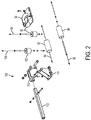
- a clamping/loading device 170 can have a pair of spaced base assemblies (first and second base assemblies 180a, 180b) and a clamping assembly 200.
- the first and second base assemblies 180a, 180b can be spaced relative to the translation axis 15.
- the loading device 170 can have a frame 202 that is securely coupled to and positioned between the first and second base assemblies 180a, 180b such that a longitudinal axis of the frame is substantially axially aligned with the translation axis 15.
- the loading device 170 can further comprise a carriage 204 that is operatively coupled to the frame 202 such that the carriage is configured for selective movement along the length of the frame relative to the translation axis 15.
- the carriage 204 can support a vice assembly 206 that defines a central space 208 for receiving a portion of a drill rod, and at least a portion of the carriage can be supported by and/or engaged by the frame 202.
- the size of the central space 208 of the vice assembly 206 can be selectively adjusted to securely engage the drill rod in an operative position.
- the vice assembly 206 can comprise first and second walls that define the central space 208, with the first wall being selectively moveable relative to the second wall using conventional means to thereby selectively adjust the width of the central space 208.
- the frame 202 can comprise first and second guide blocks 205a, 205b configured to receive a portion of the drill rod.
- first guide block 205a can be positioned proximate a first end of the frame 202 (proximate the first base assembly 180a) while the second guide block 205b can be positioned proximate a second end of the frame (proximate the second base assembly 180b).
- the vice assembly 206 can be positioned in between the first and second guide blocks 205a, 205b relative to the translation axis 15. It is further contemplated that the first and second guide blocks 205a, 205b can be substantially axially aligned with the vice assembly 206.
- the frame 202 can have a central opening 203 extending substantially along the length of the frame between the first and second base assemblies 180a, 180b.
- the loading device 170 can comprise first and second shafts 212a, 212b, with the first and second shafts 212a, 212b being supported by the frame 202. It is contemplated that the first and second shafts 212a, 212b can optionally be fully keyed drive shafts (MCMASTER CARR) defining a keyway that permits driving of a sprocket and/or wheel as further disclosed herein.
- the frame can comprise at least one bearing operatively coupled to the first shaft 212a and at least one bearing operatively coupled to the second shaft 212b.
- first base assembly 180a can optionally comprise a bearing operatively coupled to the first shaft 212a. It is further contemplated that the second base assembly 180b can optionally comprise a bearing operatively coupled to the second shaft 212b.
- the first and second shafts 212a, 212b can be supported by the frame 202 such that the shafts are oriented substantially perpendicularly to the translation axis 15 (and parallel to one another).
- the loading device 170 can further comprise a chain 210 positioned over both shafts 212a, 212b, thereby forming a closed chain loop containing both the first and second shafts, and a first portion of the chain loop can be securely coupled to the carriage 204 through the central opening 203.
- an opposed second portion of the chain loop 210 can comprise a stop element 211.
- the stop element 211 can prevent rotation of the chain loop 210 beyond predetermined rotational positions, such as, for example and without limitation, rotational positions corresponding to contact between the carriage 204 and the first or second ends (e.g., first or second guide blocks) of the frame.
- the chain 210 can be operatively coupled to the first shaft 212a such that rotation of the first shaft in a first direction effects advancement of the chain loop in a corresponding direction and the carriage 204 is advanced toward the second shaft 212b (and second base assembly 180b) relative to the translation axis 15.
- the chain 210 can also be operatively coupled to the first shaft 212a such that rotation of the first shaft in an opposed, second direction effects advancement of the chain loop in a corresponding direction and the carriage 204 is advanced toward the first shaft (and first base assembly 180a) relative to the translation axis 15.
- the loading device 170 can comprise a sprocket to operatively couple the first shaft 212a to the chain 210.
- the first shaft 212a can be operatively coupled to a wheel 214, which is configured for rotation relative to a rotation axis 215 and configured to selectively impart rotational motion to the first shaft, thereby causing advancement of the chain 210 in a desired direction.
- the frame 202 can be operatively secured to the first and second base assemblies 180a, 180b by at least one fastener. It is contemplated that the fasteners can be selectively removed to permit disassembly and transport of individual components of the clamping assembly 200. It is further contemplated that the fasteners can be selectively positioned to permit efficient assembly of the clamping assembly 200.
- first and second base assemblies 180a, 180b can comprise respective cross bars 185a, 185b. It is contemplated that the first base assembly 180a can comprise a plurality of legs 187a extending downwardly from the cross bar 185a, and the second base assembly 180b can comprise a plurality of legs 187b extending downwardly from the cross bar 185b.
- the cross bars 185a and 185b can be configured for engagement with respective end portions of the frame 202, as shown in Figure 11A .
- the first base assembly 180a can optionally comprise an arm 188 extending outwardly from the base assembly and defining a notch 189 for receiving at least a portion of the first shaft 212a.
- the height of the first and second base assemblies 180a, 180b can be selectively adjustable using conventional means.
- the legs 187a can comprise first and second leg portions, with the second leg portion configured for telescopic movement relative to the first leg portion, and each leg portion defining a plurality of axially spaced openings for receiving a locking pull pin (or other fastener) to lock the second leg portion relative to the first leg portion in the manner known in the art.
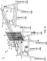
- a loading device 370 can have a pair of spaced base assemblies (first and second base assemblies 380, 390) and a driving assembly 410.
- the first and second base assemblies 380, 390 can be spaced relative to the translation axis 15. It is contemplated that the loading device 370 can be spaced from the drill head assembly. In use, the loading device 370 can selectively move the drill rod 12 relative to the translation axis 15. When the loading device 370 is used to load a drill rod 12 into a head spindle 500 as disclosed herein, it is contemplated that it is unnecessary for the loading device 370 to apply and hold torque against the drill rod 12.
- the loading device 370 can comprise first and second base assemblies 380, 390.
- the first base assembly 380 can be spaced from the second base assembly 390 relative to the translation axis 15.
- the loading device 370 can comprise a support platform 400 extending between and coupled to the first base assembly 380 and the second base assembly 390.
- the support platform 400 can have a longitudinal axis 402 substantially parallel to the translation axis 15.
- the support platform 400 can be configured to support at least a portion of the drill rod 12 as the drill rod is moved relative to the translation axis 15.
- the loading device 370 can comprise a driving assembly 410.
- the driving assembly 410 can comprise at least one driving roller 412.
- Each driving roller 412 can have a respective longitudinal axis 414.
- the longitudinal axis 414 of each driving roller 412 can be substantially perpendicular to the translation axis 15.
- each driving roller 412 can be configured for rotation about its longitudinal axis 414.
- each driving roller 412 can comprise a flexible material that is configured to also provide a surface for frictional engagement with a drill rod.
- the driving roller 412 can comprise urethane.
- the driving roller 412 can comprise carbides that are configured to frictionally engage a drill rod while minimizing damage to the drill rod.
- the driving roller 412 can comprise urethane and carbides.
- the driving assembly 410 can further comprise at least one drive assembly 415.
- Each drive assembly 415 can be positioned in operative communication with a respective driving roller 412. It is contemplated that each drive assembly 415 can be configured for selective activation to selectively rotate a respective driving roller 412.
- Each drive assembly 415 can be a hydraulic drive assembly.
- the drive assembly 415 can be any conventional type of drive assembly, such as, for example and without limitation, an electric drive assembly, a pneumatic drive assembly, or a manually-powered drive assembly.
- the driving assembly 410 can further comprise at least one guide roller 420.
- Each guide roller can have a respective longitudinal axis 422.
- the longitudinal axis 422 of each guide roller 420 can be substantially perpendicular to the translation axis 15 and substantially parallel to the longitudinal axis 414 of each respective driving roller 412.
- the at least one driving roller 412 and the at least one guide roller 420 can cooperate to define a receiving space 425.
- the receiving space 425 can be configured to receive at least a portion of the drill rod 12.
- the at least one driving roller 412 and the at least one guide roller 420 can be configured for engagement with the drill rod 12 when at least a portion of the drill rod is received within the receiving space 425.
- rotation of the at least one driving roller 412 in a first direction can be configured to advance the drill rod toward the drill head assembly relative to the translation axis 15.
- rotation of the at least one driving roller 412 in a second direction opposite the first direction can be configured to move the drill rod 12 away from the drill head assembly relative to the translation axis 15 (such as, for example, to retract a drill rod from the drill head assembly).
- the loading device 370 can optionally further comprise means for adjusting the axial position of the at least one driving roller 412 relative to a transverse axis that is perpendicular to both the longitudinal axis 414 of the at least one driving roller and the translation axis 15. It is further contemplated that the loading device 370 can optionally further comprise means for adjusting the axial position of the at least one guide roller 420 relative to the transverse axis. It is contemplated that the means for adjusting the axial position of the at least one driving roller 412 and the means for adjusting the axial position of the at least one guide roller 420 can comprise any conventional motor that is operatively coupled to a conventional power source, including, for example and without limitation, a hydraulic or electronic power source.
- the loading assembly 370 can further comprise at least one screen 430 secured to at least one of the first and second base assemblies 380, 390. It is contemplated that the screen can be secured to the first and/or second base assemblies 380, 390 to shield operators of the loading assembly 370 from contact with a drill rod 12 positioned within the support platform 400 or the receiving space 425.
- the support platform 400 can be operatively secured to the first and second base assemblies 380, 390 by at least one fastener. It is contemplated that the fasteners can be selectively removed to permit disassembly and transport of individual components of the loading assembly 370. It is further contemplated that the fasteners can be selectively positioned to permit efficient assembly of the loading assembly 370.
- the support platform 400 can optionally be foldable or otherwise collapsible to permit disassembly and transport of the support platform.
- the support platform 400 can define at least one seam corresponding to a fold location of the support platform.
- the at least one seam can comprise a plurality of seams spaced relative to the longitudinal axis 402 of the support platform 400.
- first and second base assemblies 380, 390 can comprise respective cross bars 385, 395. It is contemplated that the first base assembly 380 can comprise a plurality of legs 387 extending downwardly from the cross bar 385, and the second base assembly 390 can comprise a plurality of legs 397 extending downwardly from the cross bar 385.
- the cross bars 385 and 395 can be configured for engagement with respective end portions of the support platform 400, as shown in Figure 15 .
- first and second base assemblies 380, 390 can be provided with respective brackets that are configured to engage spaced pairs of legs 387 of the base assemblies such that a portion of each bracket extends laterally away from the base assemblies by a selected distance. It is contemplated that the portions of the brackets that extend from the base assemblies can cooperate to support a core barrel assembly when the core barrel assembly is retrieved from a drill hole while the core barrel assembly contains a core sample.
- the height of the first and second base assemblies 380, 390 can be selectively adjustable using conventional means.
- the legs 387 can comprise first and second leg portions, with the second leg portion configured for telescopic movement relative to the first leg portion, and each leg portion defining a plurality of axially spaced openings for receiving a locking pull pin (or other fastener) to lock the second leg portion relative to the first leg portion in the manner known in the art.
- the longitudinal axis 14 of the drill rod can be substantially parallel to the translation axis 15.
- the loading device 70, 170, 370 can be configured to permit movement of the drill rod 12 relative to the translation axis 15 but restrict rotation of the drill rod relative to the translation axis.
- the drill head assembly 10 can be configured to receive the drill rod 12 from the loading device 70 in an operative position.
- the drill rod handling system 150 can comprise a control assembly 120 configured to permit user-control of at least one of the drill head assembly 10 and the loading device 70, 170, 370. It is contemplated that the control assembly 120 can be positioned in operative communication with at least one of the drill head assembly 10 and the loading device 70, 170, 370. The control assembly 120 can be positioned in operative communication with both the drill head assembly 10 and the loading device 70, 170, 370. The control assembly 120 can be positioned in operative communication with the cradle 20 to effect movement of the cradle as disclosed herein.
- the control assembly 120 can be positioned in operative communication with at least one of: means for driving the lever 112, means for selectively driving the at least one support roller 92 in opposing directions, means for selectively driving the at least one clamping roller 102 in opposing directions, means for adjusting the axial position of the support assembly 90 relative to the transverse axis 72, means for adjusting the axial position of the clamping assembly 100 relative to the transverse axis 72, means for adjusting the axial position of the at least one driving roller relative to a transverse axis that is substantially perpendicular to the longitudinal axis 414 of the driving roller and to the translation axis 15, means for adjusting the axial position of the at least one guide roller relative to the transverse axis, and the drive assembly 415.
- control assembly 120 can be configured to permit selective control of these various control means.
- the control assembly can comprise a control panel 122 that is configured for selective pivotal movement relative to the remainder of the control assembly 120.
- the control assembly 120 can comprise a pivotal connection 124 as is known in the art to permit selective movement of the control panel. It is contemplated that selective pivotal movement of the control panel 122 can allow an operator of the drill head assembly 10 to orient his or her body in an optimal position to both access the control panel 122 and see the progress of ongoing operations.
- control assembly 150 can be configured cooperate with a plurality of sensors to control sequential axial and pivotal movement of a cradle of a drill head assembly as disclosed herein.
- control assembly 120 can comprise a conventional computer having a memory and a processor in operative communication with one another. It is further contemplated that the computer can have any conventional user interface. It is still further contemplated that the computer can be positioned in operative communication with the drill head assembly 10 and/or the loading device 70, 170 using any conventional communication means, including both wired communication means and wireless communication means.
- the drill rod handling system 150 can optionally comprise a hoist as is known in the art.
- the drill rod handling system 150 can comprise a foot clamp, as is known in the art, for preventing axial and rotational movement of a drill rod within a drill hole.
- the drill rod handling system 150 can optionally comprise a Kelly rod as is conventionally known in the art. It is contemplated that the loading device 70 disclosed herein can be used to translate drill shafts toward and away from the Kelly rod as further disclosed herein.
- a drilling method comprises engaging a drill rod with the loading device.
- the drilling method further comprises moving the cradle of the drill head assembly between the first position and the second position. It is contemplated that the drilling method further comprises advancing the drill rod relative to the translation axis such that a portion of the drill rod is securely threaded onto an end of a Kelly rod positioned within the opening of the chuck of the drill head assembly. More particularly, it is contemplated that the Kelly rod can be gripped by the chuck, and a male thread of the Kelly rod can be exposed below the drill head assembly, thereby permitting engagement between the thread of the Kelly rod and the new drill rod (such that the new drill rod is positioned in the operative position).
- a drilling method does not require the use of a Kelly rod.
- a drilling method can comprise engaging a drill rod with a loading device as disclosed herein.
- the drilling method can further comprise moving the cradle of the drill head assembly between the first position and the second position. It is contemplated that the drilling method can further comprise advancing the drill rod relative to the translation axis such that a portion of the drill rod is securely received within an inwardly tapered head spindle of the chuck without the use of a Kelly rod.
- a method for adding a drill rod, tripping a drill rod out of a drill hole, and tripping a drill rod into a drill hole are described below. It is contemplated that wireline operations conducted using the disclosed drill rod handling system can be substantially unchanged relative to conventional wireline operations conducted using known drilling systems.
- a drill rod can be added to a drill string during drilling operations.
- the drill head assembly can continue drilling action (rotation and feeding) until the drill approaches the bottom of its stroke, at which point the foot clamp can be closed to hold the drill string for formation of a joint.
- a gear shift of the drill head assembly can be adjusted as required to make the joint, if needed.
- the joint can be formed at the bottom of a Kelly rod.
- the gear shift of the drill head assembly can then be adjusted to shift the gears from the position used to form the joint.
- the drill head can be fed upwardly to disengage the inner and outer threads of the drill rod.
- the drill head can then be shifted laterally as disclosed herein such that the drill head is substantially laterally aligned with the clamping axis.
- the drill head can be tilted as required such that the angular orientation of the drill head substantially matches the angular orientation of the translation axis of the loading device, and the drill head can be fed downwardly as needed for axial alignment with the translation axis.
- a worker can add a rod to the loading device such that the rod is substantially aligned with the translation axis.
- the clamping assembly can then be operated to grip the rod and then axially advance the rod along the translation axis toward the Kelly rod.
- the drill head can rotate to form a joint between the Kelly rod and the new rod.
- the clamping assembly can be operated to advance the joined rod elements along the translation axis until the rod elements are positioned within the head spindle. It is contemplated that the clamping assembly can disengage the rod elements, and the chuck can then close down to grip the rod elements.
- the drill head can then be fed upwardly to accommodate the axial length of the joined rod elements (the Kelly rod and the new rod).
- the drill head can then be tilted such that the rod elements are substantially parallel to the drill mast.
- the drill head can be laterally shifted such that the joined rod elements are substantially aligned with a center line of the drill string.
- the drill head can then be fed downwardly to engage the threads of the rod elements with a drill rod already positioned within the drill hole and held in the foot clamp.
- the drill head can be rotated to form a joint between the new rod and the rod in the food clamp.
- the foot clamp can be opened to permit axial movement of the joined rod elements.
- the disclosed drill rod handling system can be used to trip a drill rod out of a drill hole.
- the hoist of the drill rod handling system can be rotated to provide tension to a drill rod hoisting cable.
- the chuck and foot clamp can be opened to permit axial movement of the drill rod.
- the hoist can then be pulled as required to remove the drill rod from the hole such that the drill rod is positioned above the foot clamp.
- the foot clamp can be closed to secure the drill rod in a position suitable for breaking the joint between the drill rod and an adjoining rod element of the drill string.
- the drill head can then be fed such that the chuck is positioned above the foot clamp.
- the chuck should be positioned about 2.5 m above the foot clamp. The chuck can then be closed on the drill rod, and the drill head can be rotated to thereby break the lowest exposed joint of the drill rod.
- the drill head can then be fed upwardly to disengage the inner and outer threads of the drill rod.
- the drill head can then be shifted laterally as disclosed herein such that the drill head is substantially laterally aligned with the clamping axis.
- the drill head can be tilted as required (typically, upwardly) until the angular orientation of the drill head substantially matches the angular orientation of translation axis of the loading device.
- the drill head can then be fed downwardly to substantially align the drill head with the translation axis of the loading device.
- the loading device can then engage the drill rod as disclosed herein, and the chuck of the drill head can be opened to permit axial movement of the drill rod.
- the loading device can be operated as required to translate the drill rod along the translation axis away from the head spindle. After the drill rod has exited the drill head, the chuck can be closed to grip the Kelly rod, and the drill head can be rotated to unthread and/or disengage a joint at the Kelly Rod.
- the loading device can continue translating the drill rod along the translation axis such that the box and pin are disengaged.
- the rod can then be removed from the loading device.
- the drill head can be fed upwardly to distance the drill head from the clamping assembly.
- the drill head can then be tilted downwardly until the head is substantially parallel with the drill mast.
- the drill head can be shifted laterally as disclosed herein such that the drill head is substantially aligned with a center line of the drill string.
- the drill head can then be fed downwardly to engage the threads of the rod being added with the rod in the foot clamp.
- the drill head can then be rotated to form a joint between the rod being added and the rod in the foot clamp.
- the drill rod handling system disclosed herein can be used to trip a drill rod into a drill hole.
- the foot clamp can be closed to hold the drill string in position for formation of a breaking joint.
- the chuck can be closed to grip the Kelly rod.
- the gears of the drill head can be shifted as required to prepare the drill head for formation of the breaking joint.
- the drill head can then be rotated to form a break joint at a bottom portion of the Kelly rod.
- the drill head can then be shifted out of its break-formation condition.
- the drill head can be fed upwardly to disengage the box and pin.
- the drill head can then be shifted laterally to substantially align with the translation axis of the loading device.
- the drill head can then be tilted to substantially align with the angular orientation of the translation axis of the loading device.
- the drill head can then be fed downwardly such that the chuck is substantially axially aligned with the translation axis of the loading device.
- a helper can then position a drill rod within the receiving channel of the loading device such that the rod is substantially aligned with the translation axis.
- the loading device can then be operated to grip the drill rod and translate the drill rod along the translation axis toward the Kelly rod.
- the drill head can then be rotated to form a joint between the new drill rod and the Kelly rod.
- the chuck can then be opened, and the loading device can be operated to further advance the drill rod (and joined Kelly rod) into the spindle of the drill head.
- the chuck can then be closed to grip the joined drill rod.
- the drill head can be fed upwardly to accommodate the combined axial length of the drill rod and the Kelly rod.
- the drill head can then be tilted such that the drill rod and Kelly rod are substantially parallel with the drill mast.
- the drill head can be shifted laterally such that the drill head is substantially aligned with a center line of the drill string.
- the drill head can be fed downwardly to engage the threads of the new rod with a drill rod element positioned within the foot clamp.
- the drill head can then be rotated to make a joint between the new rod and the rod element in the foot clamp.
- the hoist can be pulled and/or rotated to provide tension to the drilling cable.
- the chuck and foot clamp can then be opened to permit rod movement.
- the drill head can then be fed downwardly to the bottom of its stroke, and the hoist can be lowered to advance the drill string (including the newly joined drill rod) into the drill hole.
- the disclosed drill rod handling system can be used to trip a drill rod out of a drill hole without the use of a Kelly rod or a hoist.
- the chuck With a top portion of the drill rod in the drill hole above the foot clamp (e.g., for 6 meter drill rods, at about 1 meter above the foot clamp), the chuck can be closed on the drill rod above the foot clamp. Then, the foot clamp can be opened to permit axial movement of the drill rod.
- the drill head can then feed the drill rod upwardly (e.g., for six meter drill rods, upwardly at about 3 meters) to pull a selected distance of the drill rod (e.g., for six meter drill rods, the next 3 meters of the drill rod) out of the drill hole.
- the foot clamp can be closed to secure the drill rod in a position suitable for breaking the joint between the drill rod and an adjoining rod element of the drill string.
- the chuck can then be opened, and the drill head can then feed the chuck downwardly such that the chuck is positioned around the lowest drill rod to be removed from the drill hole.
- the chuck can then be closed, and the foot clamp can be opened.
- the drill head can then feed the drill rod upwardly as needed, and the foot clamp can then be closed again. With the chuck and the foot clamp closed, the drill head can be rotated to thereby break the lowest exposed joint of the drill rod.
- the drill head can then be fed upwardly to disengage the inner and outer threads of the drill rod. In some applications, this upward feeding action of the drill head can separate the box and pin.
- the drill head can then be shifted laterally as disclosed herein such that the drill head is substantially laterally aligned with the clamping axis, which generally corresponds to a center line of the loading device. After lateral shifting is completed, the drill head can be tilted as required (typically, upwardly) until the angular orientation of the drill head substantially matches the angular orientation of translation axis of the loading device. The drill head can then be fed downwardly to substantially align the drill head with the translation axis of the loading device.
- the loading device can then engage the drill rod as disclosed herein, and the chuck of the drill head can be opened to permit axial movement of the drill rod.
- the loading device can be operated as required to translate the drill rod along the translation axis and pull the drill rod out of the head spindle of the chuck. After the drill rod has exited the drill head, the operator of the loading device can remove the rod from the loading device. In some applications, when the box and pin are not previously disengaged, the loading device can continue translating the drill rod along the translation axis such that the box and pin are disengaged.
- the drill head can be fed upwardly to distance the drill head from the loading device.
- the drill head can then be tilted downwardly until the head is substantially parallel with the drill mast.
- the drill head can be shifted laterally as disclosed herein such that the drill head is substantially aligned with a center line of the drill string.
- the drill head can then be fed downwardly to engage the rod being added with the rod in the foot clamp.
- the drill head can then be rotated to form a joint between the rod being added and the rod in the foot clamp.
- the disclosed drill rod handling system can be used to trip a drill rod into a drill hole without the use of a Kelly rod or a hoist.
- the foot clamp With a top portion of a first drill rod in the drill hole above the foot clamp (e.g., for 6 meter drill rods, at about 1 meter above the foot clamp) and the drill head at the bottom of its stroke, the foot clamp can be closed to secure the first drill rod. Then, the chuck can be opened to allow the first drill rod to hang from the foot clamp. The drill head can then be fed upwardly to permit removal of the drill rod from the head spindle. To align the head spindle with a new rod in the loading device, the drill head can be shifted laterally, tilted upwardly, and fed downwardly as disclosed herein.
- the rollers of the loading device can be closed to grip a second drill rod, and the rollers can be selectively rotated to push the drill rod into the head spindle.
- the chuck can then be closed to grip the second drill rod.
- the drill head can be fed upwardly, tilted downwardly, shifted laterally, and then fed downwardly as disclosed herein to align the threads of the first and second drill rods.
- the drill head can be operatively coupled to a "make/break" switch, and upon activation of the "make/break” switch, the drill head can effect rotation of the first and second drill rods and apply sufficient torque to make a joint between the first and second drill rods.
- the foot clamp can then be opened, and the drill head can feed the first (lower) drill rod into the drill hole.
- the foot clamp can then be closed to secure the drill string in place.
- the chuck can be opened to allow the drill string to hang from the foot clamp.
- the drill head can be fed upwardly, and the chuck can be closed to grip a top portion of the second (higher) drill rod.
- the foot clamp can then be opened, and the drill head can be fed downwardly to lower the drill string into the drill hole.
Description
- This application claims priority to
U.S. Provisional Patent Application No. 61/921,830, filed December 30, 2013 U.S. Provisional Patent Application No. 62/052,712, filed September 19, 2014 - This invention relates to drill head assemblies for securing a drill rod in an operative position for drilling and rod handling operations. This invention further relates to loading devices for engaging a drill rod as it is secured to a drill head assembly.
- Prior to drilling operations, a drill rod must be secured in the chuck of a drill head assembly. Conventionally, workers use their hands to support, lift, and/or rotate a drill rod in a position that allows the chuck to threadingly engage the drill rod. Typically, a worker threads a mainline hoist plug onto a new rod. As the rod is lifted by the hoist, the worker guides an end of the new rod over a previous rod in the hole, and the chuck is rotated by hand to engage the threads of the drill rod. The chuck is then repositioned and rotated to apply sufficient torque to the rod to make the joint. Ideally, the workers will stabilize the drill rod such that the drill rod does not rotate with the chuck but is advanced axially within the chuck. However, in practice, the workers supporting the drill rod often fail to prevent rotation of the drill rod, and the workers also regularly fail to maintain the drill rod in alignment with the chuck. These issues create inefficiency in the process of engaging the drill rod with the chuck and frequently lead to worker injuries.
- Some conventional attempts at addressing these problems include floating devices, such as spline/spring assemblies, and hydraulic float devices, such as feed cylinder valves. Both of these attempts allow axial translation during rotation. However, splined floating devices are expensive and heavy and can add to the overall length of the drill head assembly. It is not always practical to apply the force required to compress the springs of these floating devices before threading and/or unthreading the joint. Furthermore, because the drill rod is not always oriented parallel to the feed cylinder, use of hydraulic float devices is not always possible.
- Additionally, due to the complexity of conventional rod loaders and rod carousels/magazines, these rod loaders and rod carousels/magazines cannot be retrofit to existing drill systems in a cost-effective manner. Moreover, these existing products only work with particular drill head and/or drill mast geometries.
- Thus, there is a need in the pertinent art for devices and systems that reduce manual drill rod handling during threading and unthreading of drill rod joints. There is a further need in the pertinent art for devices and systems that enhance the ergonomics, safety, and productivity in drill rod handling.
-
US 4,890,681 A discloses a method and apparatus for rotary power driven swivel drilling in which a rotary drive swivel unit is tilted for alignment with a horizontally approaching drill pipe, receives the horizontal drill pipe and makes up a joint with the output shaft, is reoriented under the weight of the drill pipe suspended therefrom such that it is in alignment over the drill string, and thereafter the drill pipe is added to the drill string. - Described herein is a drill head assembly for securing a drill rod in an operative position, as defined in claim 1. Preferred and optional features are set out in dependent claims 2 to 7.
- A drilling method is also defined in claim 8.
- Advantages of the invention will be set forth in part in the description which follows, and in part will be obvious from the description, or may be learned by practice of the invention. The advantages of the invention will be realized and attained by means of the elements and combinations particularly pointed out in the appended claims. It is to be understood that both the foregoing general description and the following detailed description are exemplary and explanatory only and are not restrictive of the invention, as claimed.
- These and other features of the preferred embodiments of the invention will become more apparent in the detailed description in which reference is made to the appended drawings wherein:
-
Figure 1 depicts a perspective view of an exemplary loading device as disclosed herein. -
Figure 2 depicts an exploded view of the clamping assembly of the loading device ofFigure 1 . -
Figure 3 depicts a front perspective view of an exemplary loading device as disclosed herein. -
Figure 4 depicts a perspective view of an exemplary drill head assembly as disclosed herein. -
Figure 5 depicts a top perspective view of the drill head assembly ofFigure 4 . -
Figure 6A depicts a front perspective view of an exemplary drill head assembly as disclosed herein.Figure 6B is a back perspective view of the drill head assembly ofFigure 6A . -
Figure 7 depicts a perspective view of an exemplary drill head assembly during movement of the cradle between the first and second positions as disclosed herein. -
Figures 8A-8F depict the sequential movement of a drill head assembly relative to a loading device during securing of a drill rod to the drill head assembly as disclosed herein.Figure 8A depicts the drill head assembly prior to movement of the drill head assembly relative to the longitudinal axis of the drill mast.Figure 8B depicts the drill head assembly in a first position, following movement of the drill head assembly relative to the longitudinal axis of the drill mast such that the drill head assembly is positioned proximate a drilling formation.Figure 8C depicts the drill head assembly in a second position, following axial and then pivotal movement of the drill head assembly relative to a transverse axis (perpendicular to the longitudinal axis of the drill mast). As shown, in the second position, the drill head assembly can receive a drill rod supported by the loading device.Figure 8D depicts axial movement of the drill head assembly relative to the longitudinal axis of the drill mast following engagement between the drill rod and the drill head assembly.Figure 8E depicts the drill head assembly following pivotal and then axial movement of the drill head assembly relative to the transverse axis such that the drill rod is substantially parallel to the longitudinal axis of the drill mast.Figure 8F depicts the drill head assembly in a drilling position, following axial advancement of the drill rod toward the drilling formation. -
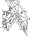
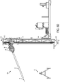
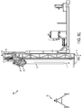
Figure 9 is a right side perspective view of a drill rod handling system comprising a loading device and a drill head assembly as disclosed herein. As shown, the loading device can support a drill rod during engagement between the drill rod and the drill head assembly. -
Figure 10 is a left side perspective view of the drill rod handling system ofFigure 9 . -
Figure 11A depicts a perspective view of another exemplary loading device as disclosed herein.Figure 11B depicts a partial exploded view of the base assembly and the clamping assembly of the loading device ofFigure 11A .Figure 11C depicts a partial exploded view of the carriage and vice assembly of the loading device ofFigure 11A . -
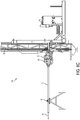
Figure 12B depicts an isolated top perspective view of the interface between the first shaft and the chain link of the loading device ofFigures 11A-11C , taken atLine 12A-12A ofFigure 12B. Figure 12B depicts a side perspective view of the loading device ofFigures 11A-11C . -
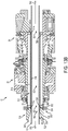
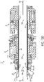
Figures 13A-13D depict longitudinal cross-sectional view of exemplary drill rod receiving assemblies positioned within a head spindle of a drill head. As shown, a receiving element of the drill rod receiving assemblies can have a tapered inner surface that cooperates with an elongate shaft to guide a drill rod into a desired orientation in which a longitudinal axis of the drill rod is substantially parallel to the longitudinal axis of the head spindle. The exemplary drill rod receiving assemblies depicted inFigures 13A-13D are configured to receive progressively larger drill rods, withFigure 13A depicting a drill rod receiving assembly for receiving a relatively small drill rod andFigure 13D depicting a drill rod receiving assembly for receiving a relatively large drill rod. -
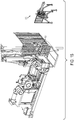
Figure 14 depicts a perspective view of an exemplary loading device as disclosed herein. -
Figure 15 is a perspective view showing the position of an exemplary control assembly relative to an exemplary loading device as disclosed herein. - The present invention can be understood more readily by reference to the following detailed description, examples, drawings, and claims, and their previous and following description. However, before the present devices, systems, and/or methods are disclosed and described, it is to be understood that this invention is not limited to the specific devices, systems, and/or methods disclosed unless otherwise specified, as such can, of course, vary. It is also to be understood that the terminology used herein is for the purpose of describing particular aspects only and is not intended to be limiting.
- The following description of the invention is provided as an enabling teaching of the invention in its best, currently known embodiment. To this end, those skilled in the relevant art will recognize and appreciate that many changes can be made to the various aspects of the invention described herein, while still obtaining the beneficial results of the present invention. It will also be apparent that some of the desired benefits of the present invention can be obtained by selecting some of the features of the present invention without utilizing other features. Accordingly, those who work in the art will recognize that many modifications and adaptations to the present invention are possible and can even be desirable in certain circumstances and are a part of the present invention. Thus, the following description is provided as illustrative of the principles of the present invention and not in limitation thereof.
- As used throughout, the singular forms "a," "an" and "the" include plural referents unless the context clearly dictates otherwise. Thus, for example, reference to "a roller" can include two or more such rollers unless the context indicates otherwise.
- Ranges can be expressed herein as from "about" one particular value, and/or to "about" another particular value. When such a range is expressed, another aspect includes from the one particular value and/or to the other particular value. Similarly, when values are expressed as approximations, by use of the antecedent "about," it will be understood that the particular value forms another aspect. It will be further understood that the endpoints of each of the ranges are significant both in relation to the other endpoint, and independently of the other endpoint.
- As used herein, the terms "optional" or "optionally" mean that the subsequently described event or circumstance may or may not occur, and that the description includes instances where said event or circumstance occurs and instances where it does not.
- The word "or" as used herein means any one member of a particular list and also includes any combination of members of that list.
- Described herein with reference to
Figures 1-15 is a drillrod handling system 150 for positioning adrill rod 12 in an operative position. The drillrod handling system 150 can comprise aloading device drill mast 16, and adrill head assembly 10 according to the invention. Thedrill mast 16 and thedrill rod 12 can have respectivelongitudinal axes rod handling system 150 can substantially eliminate the need for direct contact between an operator of the drill rod handling system and a drill rod to be loaded or unloaded from thedrill head assembly 10. It is further contemplated that the drillrod handling system 150 can operate as fast as current drill loading and unloading methods while offering a cost reduction. - With reference to
Figures 4-10 and13A-13D , thedrill head assembly 10 is for use in securing thedrill rod 12 in the operative position. Thedrill head assembly 10 is operatively coupled to thedrill mast 16. It is contemplated that thedrill head assembly 10 can comprise a motor and a gear box as are known in the art. It is contemplated that the discloseddrill head assembly 10 can be retrofit and/or added to an existing drilling system, such as, for example and without limitation, the LF™ 90D Surface Coring Drill system manufactured by BOART LONGYEAR (South Jordan, Utah). - The
drill head assembly 10 comprises acradle 20, achuck 30 operatively supported by the cradle, and can comprise agear box portion 36. Thecradle 20 is operatively configured for movement relative to both thelongitudinal axis 18 of the drill mast 16and atransverse axis 19 substantially perpendicular to thelongitudinal axis 18 of thedrill mast 16. . Optionally, the chuck can be a NITRO CHUCK™ (BOART LONGYEAR, South Jordan, Utah) chuck. However, it is contemplated that thechuck 30 can be any conventional chuck that is configured to grip drill shafts and spin with a head spindle as is known in the art. - The
chuck 30 has alongitudinal axis 32 and defines anopening 34. Theopening 34 of thechuck 30 can be configured to securely receive a portion of a Kelly rod as is known in the art. It is contemplated that the Kelly rod can be configured for engagement with a portion of thedrill rod 12 such that thelongitudinal axis 14 of thedrill rod 12 is substantially axially aligned with thelongitudinal axis 32 of thechuck 30. - Optionally, it is contemplated that the
drill rod 12 can be positioned within thechuck 30 without the need of a Kelly rod as is known in the art. With reference toFigures 13A-13D , it is contemplated that thedrill head assembly 10 can comprise ahead spindle 35 that spans between thegear box portion 36 and thechuck portion 30 of thedrill head assembly 10. A drill rod receiving assembly 500 for receiving thedrill rod 12 can be provided. With reference toFigure 13A-13D , the drill rod receiving assembly 500 can have alongitudinal axis 502 and be configured for positioning within thehead spindle 35 of thedrill head 10 such that the longitudinal axis of the drill rod receiving assembly is substantially aligned with a longitudinal axis of the head spindle. - The drill rod receiving assembly 500 can comprise an
elongate shaft 510 having afirst end 512, an opposedsecond end 514, aninner surface 516, and anouter surface 518. Theinner surface 516 of theelongate shaft 510 can define abore 520 extending between the first and second ends 512, 514 of theelongate shaft 510. It is contemplated that thefirst end 512 of theelongate shaft 510 can define afirst opening 522 in communication with thebore 520. It is further contemplated that thesecond end 514 of theelongate shaft 510 can be configured for receipt within thechuck portion 30 of thedrill head 10. - The drill rod receiving assembly 500 can comprise a receiving
element 530 configured for operative coupling to thegear box portion 36 of thedrill head 10. The receivingelement 530 can have afirst end 532, an opposedsecond end 534, aninner surface 536, and anouter surface 538. Theinner surface 536 of the receivingelement 530 can define abore 540 extending between the first and second ends 532, 534 of the receiving element. Thefirst end 532 of the receivingelement 530 can define afirst opening 542 in communication with thebore 540. Thesecond end 534 of the receivingelement 530 can define asecond opening 544 in communication with thebore 540. It is contemplated that at least a portion of theinner surface 536 of the receivingelement 530 can be inwardly tapered moving from thefirst opening 542 toward thesecond opening 544. At least a portion of theinner surface 536 of the receivingelement 530 can be angled relative to thelongitudinal axis 502 of the drill rod receiving assembly 500 at an angle ranging from about 10 degrees to about 45 degrees and, more preferably, about 15 degrees. Thus, theinner surface 536 of the receivingelement 530 can be configured to provide between about 20 and about 90 degrees of tolerance during insertion of thedrill rod 12 into thefirst opening 542 of the receivingelement 530. It is contemplated this tolerance can permit receipt of a wide range of drill rods that are not axially aligned with thefirst opening 542 of the receivingelement 530. It is further contemplated that thesecond end 534 of the receivingelement 530 can be operatively coupled to thefirst end 512 of theelongate shaft 510 such that thesecond opening 544 of the receivingelement 530 is substantially aligned and in communication with thefirst opening 522 of the elongate shaft. - Upon advancement of the
drill rod 10 from thefirst opening 542 of the receivingelement 530 toward thesecond end 514 of theelongate shaft 510, theinner surfaces drill rod 12 is substantially parallel to the longitudinal axis of the head spindle. It is contemplated that the longitudinal axis of thedrill rod 12 can also be substantially parallel to (or in alignment with) thetranslation axis 15 of a loading device as further disclosed herein. Unlike known drill heads, the disclosed drill rod receiving assembly 500 can receive a drill rod in the desired orientation without the need for threading joints to pass the drill rod to a drilling assembly. During use of the disclosed drill rod receiving assembly 500, only axial advancement (i.e., pushing) of the drill rod is needed to correctly position the drill rod within the assembly 500. - Optionally, the drill rod receiving assembly 500 can further comprise a
plate assembly 550. Theplate assembly 550 can comprise afirst plate 552 configured for circumferential engagement with the outer surface of thehead spindle 35 of thedrill head 10 and asecond plate 554 configured to circumferentially engage a portion of theouter surface 538 of the receivingelement 530 proximate thesecond end 534 of the receiving element. Theplate assembly 550 can further comprise means for securely coupling thefirst plate 552 to thesecond plate 554 to thereby stabilize the receiving element. The means for securely coupling the first plate to the second plate can comprise at least one fastener configured to securely couple thefirst plate 552 to thesecond plate 554. It is contemplated that the at least one fastener can comprise a plurality of fasteners. It is further contemplated that each fastener of the at least one fastener can comprise any conventional fastener as is known in the art, including, for example and without limitation, a bolt, a screw, a pin, and the like. It is contemplated that the means for securely coupling the first plate to the second plate can comprise a snap ring as is known in the art. The snap ring can be configured for operative engagement with an inner portion of thesecond plate 554 such that the snap ring is positioned between the second plate and theouter surface 538 of the receivingelement 530. - Optionally, the drill rod receiving assembly 500 can further comprise a plurality of
spacers 560. Eachspacer 560 of the plurality of spacers can be configured to circumferentially surround a portion of theouter surface 518 of theelongate shaft 510 and to maintain the spacing between the outer surface of the elongate shaft and an inner surface of the head spindle. - It is contemplated that at least a portion of the
inner surface 516 of theelongate shaft 510 can be configured for engagement with a portion of thedrill rod 12 to support the drill rod in alignment with thelongitudinal axis 502 of the receiving assembly 500 (and, thus, with the longitudinal axis of the chuck 30). In operation, adrill rod 12 can be inserted into thefirst opening 542 of the receivingelement 530 and then advanced relative to thelongitudinal axis 502 of the receiving assembly 500 such that the drill rod is received in thesecond opening 544 of the receiving element and then axially advanced through thefirst opening 522 of theelongate shaft 510 until the drill rod passes through thesecond opening 524 of the elongate shaft. As further described above, it is contemplated that the inwardly tapered profile of the receivingelement 530 can accommodate receipt of drill rods positioned at a wide range of angles and then help establish alignment of the drill rod with thelongitudinal axis 502 of the receiving assembly 500 as the drill rods are advanced toward thesecond opening 524 of the elongate shaft. It is further contemplated that the inwardly tapered profile of the receivingelement 530 can be useful in a variety of operating conditions, including, for example and without limitation, when deflection occurs during feeding of a drill head down over a drill rod positioned within a foot clamp or during the addition of a drill rod onto a spindle. It is contemplated that the receivingelement 530 and theelongate shaft 510 can be configured to prevent contact between thedrill rod 12 and thechuck 30 until the drill rod is adequately positioned within the jaws of the chuck. - It is contemplated that the
elongate shaft 510 can have a substantially constant inner diameter (defined by inner surface 516) and a substantially constant outer diameter (defined by outer surface 518). - Optionally, it is contemplated that the receiving
element 530 of the receiving assembly 500 can be selectively detachable from thehead spindle 35 and theelongate shaft 510 of the receiving assembly. It is further contemplated that eachelongate shaft 510 can be selectively removed from thedrill head 10. It is contemplated that each respective receivingelement 530 can be configured for operative connection to a correspondingelongate shaft 510. Thus, it is contemplated that, for a givendrill rod 12, a suitably sizedelongate shaft 510 and corresponding receivingelement 530 can be selected for usage with thedrill head 10 to permit advancement of the drill rod as disclosed herein.Figures 13A-13D depict various drill rods being advanced within suitably sized elongate shafts and their complementary receiving elements. As can be appreciated, as the diameter of thedrill rod 12 to be inserted within thedrill head 10 increases, the inner diameter of theelongate shaft 510 and at least a minimum inner diameter of the receivingelement 530 increase, whereas the dimensions of the spacers 560 (which may not be used depending upon the diameter of the drill rod) decrease. - The
cradle 20 is configured for movement between a first position and a second position. As shown inFigures 8A-8B , in the first position, it is contemplated that thelongitudinal axis 32 of thechuck 30 is substantially parallel to thelongitudinal axis 18 of thedrill mast 16. From the first position, thecradle 20 is configured for sequential axial and then pivotal (or, alternatively, sequential pivotal and then axial) movement relative to thetransverse axis 19 to reach the second position. As shown inFigure 8C , in the second position, it is contemplated that thelongitudinal axis 32 of thechuck 30 is substantially perpendicular to thelongitudinal axis 18 of thedrill mast 16. Optionally, in the second position, thecradle 20 can be axially spaced from thedrill mast 16 relative to thetransverse axis 19. From the second position, thecradle 20 can be configured for sequential pivotal and then axial (or, alternatively, sequential axial and then pivotal) movement relative to thetransverse axis 19 to return to the first position. However, depending on the length of the drill rod, it will be appreciated that it may be necessary to lift thecradle 20 axially relative to thelongitudinal axis 18 of thedrill mast 16 before the cradle is sequentially pivotally and then axially moved relative to thetransverse axis 19. - During movement of the
cradle 20 between the first and second positions, pivotal movement of the cradle is restricted until the completion of axial movement relative to thetransverse axis 19. It is further contemplated that axial movement of thecradle 20 relative to thetransverse axis 19 can be restricted until the completion of pivotal movement of the cradle relative to the transverse axis. Thus, it is contemplated that, in use, the cradle 20 (and, thus, the chuck 30) will not axially shift during tilting of the cradle relative to thetransverse axis 19, such as, for example, while it is tilting during movement of the cradle from the second position to the first position. Similarly, it is contemplated that, in use, the cradle 20 (and, thus, the chuck 30) will not tilt while the cradle is shifting axially relative to thetransverse axis 19, such as, for example, while it is shifting axially from the first position to the second position. It is contemplated that, by requiring a full axial shift before tilting occurs and/or a full tilt before axial shifting occurs, many of the safety risks associated with conventional drill head assemblies can be avoided. - The
drill head assembly 10 comprises a plurality ofsensors 40. At least onesensor 40 of the plurality of sensors is configured to detect the completion of axial movement of thecradle 20 relative to thetransverse axis 19. It is contemplated that at least onesensor 40 of the plurality of sensors is configured to detect the completion of pivotal movement of thecradle 20 relative to thetransverse axis 19. Optionally, the plurality ofsensors 40 can comprise a plurality of proximity switches operatively coupled in a relay configuration. However, it is contemplated that any conventional position sensors, such as, for example and without limitation, electrical position sensors, programmable logic controllers (PLC's), and the like, can be used. - The plurality of
sensors 40 can optionally comprise a plurality of hydraulic sequence valves. Thedrill head assembly 10 can further comprise a firsthydraulic cylinder 50 operatively coupled to the cradle and positioned in communication with the plurality of hydraulic sequence valves. It is contemplated that the firsthydraulic cylinder 50 can optionally have a longitudinal axis substantially parallel to the transverse axis. It is further contemplated that activation of the firsthydraulic cylinder 50 can be configured to effect axial movement of thecradle 20 relative to thetransverse axis 19. Thedrill head assembly 10 can further comprise a secondhydraulic cylinder 52 operatively coupled to thecradle 20 and positioned in communication with the plurality of hydraulic sequence valves. It is contemplated that activation of the secondhydraulic cylinder 52 can be configured to effect pivotal movement of thecradle 20 relative to thetransverse axis 19. In use, it is contemplated that oil can be diverted between the first and secondhydraulic cylinders cradle 20 andchuck 30. - The plurality of
sensors 40 and the first and secondhydraulic cylinders control assembly 120 as further described herein. Optionally, it is contemplated that sequential axial and then pivotal movement of the cradle from the first position to the second position can be effected by a single action by an operator of thecontrol assembly 120. It is further contemplated that sequential pivotal and then axial movement of the cradle from the second position to the first position can be effected by a single action by an operator of the control assembly. For example, it is contemplated that thecontrol assembly 120 can comprise a first lever (or other user input means) that can be activated to effect movement of the cradle from the first position to the second position as disclosed herein and a second lever (or other user input means) that can be activated to effect movement of the cradle from the second position to the first position as disclosed herein. Alternatively, it is contemplated that movement about and between the first and second positions can be accomplished using a single lever (or other user input means) having two or more operative positions, with one operative position effecting movement from the first position to the second position and a second operative position effecting movement from the second position to the first position. Separately, thecontrol assembly 120 can comprise one or more additional user input means for effecting movement of the cradle relative to thelongitudinal axis 18 of thedrill mast 16. In operation, thecontrol assembly 120 can communicate with the plurality ofsensors 40 and thehydraulic cylinders control assembly 120 directs the plurality of sensors to move the cradle from the first position to the second position, the control assembly can actuate the first hydraulic cylinder to effect axial movement of the cradle relative to the transverse axis. When a sensor of the plurality of sensors detects that axial movement of the cradle relative to the transverse axis has been completed, the sensor and/or the control assembly can effect sequential actuation of the second hydraulic cylinder (e.g., in a relay configuration) to thereby effect pivotal movement of the cradle relative to the transverse axis; however, the control assembly cooperates with the plurality of sensors to prevent pivotal movement of the cradle until axial movement has been completed. A sensor of the plurality of sensors can also determine when pivotal movement of the cradle has been completed, thereby confirming positioning of the cradle in the second position. Similarly, when thecontrol assembly 120 directs the plurality of sensors to move the cradle from the second position to the first position, the control assembly can actuate the second hydraulic cylinder to effect pivotal movement of the cradle relative to the transverse axis. When a sensor of the plurality of sensors detects that pivotal movement of the cradle relative to the transverse axis has been completed, the sensor and/or the control assembly can effect sequential actuation of the first hydraulic cylinder (e.g., in a relay configuration) to thereby effect axial movement of the cradle relative to the transverse axis; however, the control assembly cooperates with the plurality of sensors to prevent axial movement of the cradle until pivotal movement has been completed. A sensor of the plurality of sensors can also determine when axial movement of the cradle has been completed, thereby confirming positioning of the cradle has been returned to the first position. - The
drill head assembly 10 can further comprise a plurality of spaced guide bars 60 operatively coupled to thecradle 20. Eachguide bar 60 of the plurality of guide bars can have a longitudinal axis substantially parallel to thetransverse axis 19. It is contemplated that thecradle 20 can be configured for movement along the plurality of guide bars 60 relative to thetransverse axis 19. It is further contemplated that the plurality of guide bars 60 can be configured to support thecradle 20 during axial and pivotal movement of the cradle relative to thetransverse axis 19. During or following tilting of thecradle 20, it is contemplated that the plurality of spaced guide bars 60 must fully support thecradle 20 before thedrill head assembly 10 will be permitted to axially shift relative to thetransverse axis 19. - With reference to
Figures 1-3 and8A-10 , theloading device 70 can be used for engaging adrill rod 12 moving relative to atranslation axis 15. Theloading device 70 can optionally comprise abase assembly 80, asupport assembly 90, and a clampingassembly 100. - The
base assembly 80 of theloading device 70 can comprise at least one horizontal roller. It is contemplated that the at least one horizontal roller can comprise a single horizontal roller. Optionally, the at least one horizontal roller can comprise at least oneproximal roller 82 and at least onedistal roller 86. The at least oneproximal roller 82 can be spaced from the at least onedistal roller 86. It is contemplated that the proximal anddistal rollers longitudinal axes longitudinal axes 84 of the at least oneproximal roller 82 can be substantially parallel to thelongitudinal axes 88 of the at least onedistal roller 86. It is still further contemplated that thelongitudinal axes distal rollers translation axis 15. - The
support assembly 90 of theloading device 70 can be secured to thebase assembly 80. Thesupport assembly 90 can comprise at least onesupport roller 92. Optionally, the at least onesupport roller 92 can comprise a plurality of support rollers. It is contemplated that eachsupport roller 92 of the at least one support roller can have a respectivelongitudinal axis 94. It is further contemplated that thelongitudinal axes 94 of the at least onesupport roller 92 can be substantially parallel. It is still further contemplated that thelongitudinal axes 94 of the at least onesupport roller 92 can be substantially perpendicular to thetranslation axis 15 and thelongitudinal axes distal rollers - The clamping
assembly 100 of theloading device 70 can be spaced from thesupport assembly 90 relative to atransverse axis 72. Thetransverse axis 72 can optionally be substantially parallel to thelongitudinal axes distal rollers assembly 100 can have at least oneclamping roller 102 configured for movement relative to thetransverse axis 72 between an open position and an engaged position. It is further contemplated that the at least oneclamping roller 102 can have alongitudinal axis 104 that is substantially parallel to thelongitudinal axes 94 of the at least onesupport roller 92. Optionally, the at least oneclamping roller 102 can comprise a plurality of clamping rollers. It is contemplated that each clampingroller 102 can comprise a flexible material that is configured to also provide a surface for frictional engagement with a drill rod. Optionally, the clampingroller 102 can comprise urethane. The clampingroller 102 can comprise carbides that are configured to frictionally engage a drill rod while minimizing damage to the drill rod. The clampingroller 102 can comprise urethane and carbides. - The horizontal, support, and clamping
rollers space 74. The receivingspace 74 can be configured to receive at least a portion of thedrill rod 12. It is contemplated that, in the engaged position of the clampingroller 102, the horizontal, support, and clampingrollers drill rod 12. It is further contemplated that, in the engaged position of the at least oneclamping roller 102, the horizontal, support, and clampingrollers drill rod 12 relative to thetranslation axis 15 but restrict rotation of the drill rod relative to the translation axis. - The
loading device 70 can further comprise alever 112. Thelever 112 can have alever support 114 secured to thebase assembly 80 and acoupling element 116 coupled to thelever 112 and the at least oneclamping roller 102. It is contemplated that thecoupling element 116 can be pivotally coupled to thelever support 114. It is further contemplated that thecoupling element 116 can be configured for pivotal movement relative to thelever support 114. It is contemplated that selective pivotal movement of thecoupling element 116 can effect movement of the clampingroller 102 relative to thetransverse axis 72. It is contemplated that the position of at least one of thelever support 114 and thesupport assembly 90 can be selectively adjustable relative to thetransverse axis 72. Optionally, in exemplary aspects, theloading device 70 can comprise means for driving thelever 112. The means for driving thelever 112 can be configured to selectively move the lever, thereby effecting movement of thecoupling element 116 and/or the clampingroller 102. Theloading device 70 can comprise means for driving the at least onesupport roller 92. The means for driving the at least onesupport roller 92 can be configured to selectively rotate the at least one support roller. It is still further contemplated that theloading device 70 can further comprise means for adjusting the axial position of thesupport assembly 90 relative to thetransverse axis 72 and/or means for adjusting the axial position of the clampingassembly 100 relative to thetransverse axis 72. It is contemplated that the means for driving thelever 112, the means for driving the at least onesupport roller 92, the means for adjusting the axial position of thesupport assembly 90, and the means for adjusting the axial position of the clampingassembly 100 can comprise any conventional motor that is operatively coupled to a conventional power source, including, for example and without limitation, a hydraulic or electronic power source. - The
lever 112 can have alongitudinal axis 113. In the open position of the at least oneclamping roller 102, thelongitudinal axis 113 of the lever can be substantially parallel to thetransverse axis 72. It is contemplated that the at least oneclamping roller 102 can be moveable from the open position to the engaged position upon application of a downward force to thelever 112. It is further contemplated that, in the engaged position of the at least oneclamping roller 102, thelongitudinal axis 113 of thelever 112 can be angled downwardly relative to thetransverse axis 72. Theloading device 70 can comprise means for driving the at least oneclamping roller 102. The means for driving the at least oneclamping roller 102 can be configured to selectively rotate the at least oneclamping roller 102. It is contemplated that the means for driving the at least oneclamping roller 102 can comprise any conventional motor that is operatively coupled to a conventional power source, including, for example and without limitation, a hydraulic or electronic power source. - The
base assembly 80 of theloading device 70 can further comprise a cross-bar 85. It is contemplated that the proximal anddistal rollers base assembly 80 can be positioned on opposing sides of the cross-bar 85. Optionally, it is further contemplated that thebase assembly 80 can further comprise a plurality oflegs 87 secured to the cross-bar 85. - Optionally, the at least one
clamping roller 102 of the clampingassembly 100 can comprise a single clamping roller. It is contemplated that the at least onesupport roller 92 of thesupport assembly 90 can comprise two support rollers. It is further contemplated that thesingle clamping roller 102 can be substantially axially centered between the twosupport rollers 92 relative to thetranslation axis 15. - It is contemplated that the proximal and
distal rollers base assembly 80 can be positioned at substantially the same height. It is contemplated that the support and clampingrollers - It is contemplated that the height of the
base assembly 80 can be selectively adjustable using conventional means. In one non-limiting example, thelegs 87 can comprise first and second leg portions, with the second leg portion configured for telescopic movement relative to the first leg portion, and each leg portion defining a plurality of axially spaced openings for receiving a locking pull pin (or other fastener) to lock the second leg portion relative to the first leg portion in the manner known in the art. - Referring to
Figures 11A-12B , a clamping/loading device 170 can have a pair of spaced base assemblies (first andsecond base assemblies second base assemblies translation axis 15. - The
loading device 170 can have aframe 202 that is securely coupled to and positioned between the first andsecond base assemblies translation axis 15. Theloading device 170 can further comprise acarriage 204 that is operatively coupled to theframe 202 such that the carriage is configured for selective movement along the length of the frame relative to thetranslation axis 15. Thecarriage 204 can support avice assembly 206 that defines acentral space 208 for receiving a portion of a drill rod, and at least a portion of the carriage can be supported by and/or engaged by theframe 202. It is contemplated that the size of thecentral space 208 of thevice assembly 206 can be selectively adjusted to securely engage the drill rod in an operative position. For example, thevice assembly 206 can comprise first and second walls that define thecentral space 208, with the first wall being selectively moveable relative to the second wall using conventional means to thereby selectively adjust the width of thecentral space 208. Optionally, theframe 202 can comprise first andsecond guide blocks 205a, 205b configured to receive a portion of the drill rod. It is contemplated that the first guide block 205a can be positioned proximate a first end of the frame 202 (proximate thefirst base assembly 180a) while thesecond guide block 205b can be positioned proximate a second end of the frame (proximate thesecond base assembly 180b). Thus, it is contemplated that thevice assembly 206 can be positioned in between the first andsecond guide blocks 205a, 205b relative to thetranslation axis 15. It is further contemplated that the first andsecond guide blocks 205a, 205b can be substantially axially aligned with thevice assembly 206. - Optionally, the
frame 202 can have acentral opening 203 extending substantially along the length of the frame between the first andsecond base assemblies loading device 170 can comprise first and second shafts 212a, 212b, with the first and second shafts 212a, 212b being supported by theframe 202. It is contemplated that the first and second shafts 212a, 212b can optionally be fully keyed drive shafts (MCMASTER CARR) defining a keyway that permits driving of a sprocket and/or wheel as further disclosed herein. Optionally, the frame can comprise at least one bearing operatively coupled to the first shaft 212a and at least one bearing operatively coupled to the second shaft 212b. It is contemplated that thefirst base assembly 180a can optionally comprise a bearing operatively coupled to the first shaft 212a. It is further contemplated that thesecond base assembly 180b can optionally comprise a bearing operatively coupled to the second shaft 212b. The first and second shafts 212a, 212b can be supported by theframe 202 such that the shafts are oriented substantially perpendicularly to the translation axis 15 (and parallel to one another). Theloading device 170 can further comprise achain 210 positioned over both shafts 212a, 212b, thereby forming a closed chain loop containing both the first and second shafts, and a first portion of the chain loop can be securely coupled to thecarriage 204 through thecentral opening 203. Optionally, an opposed second portion of thechain loop 210 can comprise astop element 211. In operation, it is contemplated that thestop element 211 can prevent rotation of thechain loop 210 beyond predetermined rotational positions, such as, for example and without limitation, rotational positions corresponding to contact between thecarriage 204 and the first or second ends (e.g., first or second guide blocks) of the frame. Thechain 210 can be operatively coupled to the first shaft 212a such that rotation of the first shaft in a first direction effects advancement of the chain loop in a corresponding direction and thecarriage 204 is advanced toward the second shaft 212b (andsecond base assembly 180b) relative to thetranslation axis 15. It is contemplated that thechain 210 can also be operatively coupled to the first shaft 212a such that rotation of the first shaft in an opposed, second direction effects advancement of the chain loop in a corresponding direction and thecarriage 204 is advanced toward the first shaft (andfirst base assembly 180a) relative to thetranslation axis 15. Optionally, it is contemplated that theloading device 170 can comprise a sprocket to operatively couple the first shaft 212a to thechain 210. The first shaft 212a can be operatively coupled to a wheel 214, which is configured for rotation relative to a rotation axis 215 and configured to selectively impart rotational motion to the first shaft, thereby causing advancement of thechain 210 in a desired direction. - Optionally, the
frame 202 can be operatively secured to the first andsecond base assemblies - Optionally, the first and
second base assemblies respective cross bars 185a, 185b. It is contemplated that thefirst base assembly 180a can comprise a plurality oflegs 187a extending downwardly from the cross bar 185a, and thesecond base assembly 180b can comprise a plurality oflegs 187b extending downwardly from thecross bar 185b. Optionally, it is contemplated that the cross bars 185a and 185b can be configured for engagement with respective end portions of theframe 202, as shown inFigure 11A . Thefirst base assembly 180a can optionally comprise an arm 188 extending outwardly from the base assembly and defining a notch 189 for receiving at least a portion of the first shaft 212a. - It is contemplated that the height of the first and
second base assemblies legs 187a can comprise first and second leg portions, with the second leg portion configured for telescopic movement relative to the first leg portion, and each leg portion defining a plurality of axially spaced openings for receiving a locking pull pin (or other fastener) to lock the second leg portion relative to the first leg portion in the manner known in the art. - Referring to
Figures 14-15 , aloading device 370 can have a pair of spaced base assemblies (first andsecond base assemblies 380, 390) and a drivingassembly 410. The first andsecond base assemblies translation axis 15. It is contemplated that theloading device 370 can be spaced from the drill head assembly. In use, theloading device 370 can selectively move thedrill rod 12 relative to thetranslation axis 15. When theloading device 370 is used to load adrill rod 12 into a head spindle 500 as disclosed herein, it is contemplated that it is unnecessary for theloading device 370 to apply and hold torque against thedrill rod 12. - With reference to
Figure 14 , theloading device 370 can comprise first andsecond base assemblies first base assembly 380 can be spaced from thesecond base assembly 390 relative to thetranslation axis 15. - With reference to
Figure 14 , theloading device 370 can comprise asupport platform 400 extending between and coupled to thefirst base assembly 380 and thesecond base assembly 390. Thesupport platform 400 can have a longitudinal axis 402 substantially parallel to thetranslation axis 15. Thesupport platform 400 can be configured to support at least a portion of thedrill rod 12 as the drill rod is moved relative to thetranslation axis 15. - With reference to
Figure 14 , theloading device 370 can comprise a drivingassembly 410. The drivingassembly 410 can comprise at least one drivingroller 412. Each drivingroller 412 can have a respectivelongitudinal axis 414. Optionally, thelongitudinal axis 414 of each drivingroller 412 can be substantially perpendicular to thetranslation axis 15. In operation, each drivingroller 412 can be configured for rotation about itslongitudinal axis 414. It is contemplated that each drivingroller 412 can comprise a flexible material that is configured to also provide a surface for frictional engagement with a drill rod. Optionally, the drivingroller 412 can comprise urethane. The drivingroller 412 can comprise carbides that are configured to frictionally engage a drill rod while minimizing damage to the drill rod. The drivingroller 412 can comprise urethane and carbides. - With reference to
Figure 14 , the drivingassembly 410 can further comprise at least onedrive assembly 415. Eachdrive assembly 415 can be positioned in operative communication with arespective driving roller 412. It is contemplated that each drive assembly 415 can be configured for selective activation to selectively rotate arespective driving roller 412. Eachdrive assembly 415 can be a hydraulic drive assembly. However, it is contemplated that thedrive assembly 415 can be any conventional type of drive assembly, such as, for example and without limitation, an electric drive assembly, a pneumatic drive assembly, or a manually-powered drive assembly. - With reference to
Figure 14 , the drivingassembly 410 can further comprise at least oneguide roller 420. Each guide roller can have a respectivelongitudinal axis 422. Optionally, thelongitudinal axis 422 of eachguide roller 420 can be substantially perpendicular to thetranslation axis 15 and substantially parallel to thelongitudinal axis 414 of eachrespective driving roller 412. The at least one drivingroller 412 and the at least oneguide roller 420 can cooperate to define a receivingspace 425. The receivingspace 425 can be configured to receive at least a portion of thedrill rod 12. - In use, the at least one driving
roller 412 and the at least oneguide roller 420 can be configured for engagement with thedrill rod 12 when at least a portion of the drill rod is received within the receivingspace 425. When at least a portion of thedrill rod 12 is received within the receivingspace 425, rotation of the at least one drivingroller 412 in a first direction can be configured to advance the drill rod toward the drill head assembly relative to thetranslation axis 15. It is contemplated that rotation of the at least one drivingroller 412 in a second direction opposite the first direction can be configured to move thedrill rod 12 away from the drill head assembly relative to the translation axis 15 (such as, for example, to retract a drill rod from the drill head assembly). - It is contemplated that the
loading device 370 can optionally further comprise means for adjusting the axial position of the at least one drivingroller 412 relative to a transverse axis that is perpendicular to both thelongitudinal axis 414 of the at least one driving roller and thetranslation axis 15. It is further contemplated that theloading device 370 can optionally further comprise means for adjusting the axial position of the at least oneguide roller 420 relative to the transverse axis. It is contemplated that the means for adjusting the axial position of the at least one drivingroller 412 and the means for adjusting the axial position of the at least oneguide roller 420 can comprise any conventional motor that is operatively coupled to a conventional power source, including, for example and without limitation, a hydraulic or electronic power source. - Optionally, as shown in
Figure 14 , theloading assembly 370 can further comprise at least onescreen 430 secured to at least one of the first andsecond base assemblies second base assemblies loading assembly 370 from contact with adrill rod 12 positioned within thesupport platform 400 or the receivingspace 425. - Optionally, the
support platform 400 can be operatively secured to the first andsecond base assemblies loading assembly 370. It is further contemplated that the fasteners can be selectively positioned to permit efficient assembly of theloading assembly 370. Thesupport platform 400 can optionally be foldable or otherwise collapsible to permit disassembly and transport of the support platform. Optionally, thesupport platform 400 can define at least one seam corresponding to a fold location of the support platform. Optionally, the at least one seam can comprise a plurality of seams spaced relative to the longitudinal axis 402 of thesupport platform 400. - Optionally, the first and
second base assemblies first base assembly 380 can comprise a plurality oflegs 387 extending downwardly from thecross bar 385, and thesecond base assembly 390 can comprise a plurality oflegs 397 extending downwardly from thecross bar 385. Optionally, it is contemplated that the cross bars 385 and 395 can be configured for engagement with respective end portions of thesupport platform 400, as shown inFigure 15 . - As shown in
Figure 14 , the first andsecond base assemblies legs 387 of the base assemblies such that a portion of each bracket extends laterally away from the base assemblies by a selected distance. It is contemplated that the portions of the brackets that extend from the base assemblies can cooperate to support a core barrel assembly when the core barrel assembly is retrieved from a drill hole while the core barrel assembly contains a core sample. - It is contemplated that the height of the first and
second base assemblies legs 387 can comprise first and second leg portions, with the second leg portion configured for telescopic movement relative to the first leg portion, and each leg portion defining a plurality of axially spaced openings for receiving a locking pull pin (or other fastener) to lock the second leg portion relative to the first leg portion in the manner known in the art. - Upon engagement between the
loading device drill rod 12, it is contemplated that thelongitudinal axis 14 of the drill rod can be substantially parallel to thetranslation axis 15. As disclosed herein, it is contemplated that theloading device drill rod 12 relative to thetranslation axis 15 but restrict rotation of the drill rod relative to the translation axis. In use, thedrill head assembly 10 can be configured to receive thedrill rod 12 from theloading device 70 in an operative position. - The drill
rod handling system 150 can comprise acontrol assembly 120 configured to permit user-control of at least one of thedrill head assembly 10 and theloading device control assembly 120 can be positioned in operative communication with at least one of thedrill head assembly 10 and theloading device control assembly 120 can be positioned in operative communication with both thedrill head assembly 10 and theloading device control assembly 120 can be positioned in operative communication with thecradle 20 to effect movement of the cradle as disclosed herein. Thecontrol assembly 120 can be positioned in operative communication with at least one of: means for driving thelever 112, means for selectively driving the at least onesupport roller 92 in opposing directions, means for selectively driving the at least oneclamping roller 102 in opposing directions, means for adjusting the axial position of thesupport assembly 90 relative to thetransverse axis 72, means for adjusting the axial position of the clampingassembly 100 relative to thetransverse axis 72, means for adjusting the axial position of the at least one driving roller relative to a transverse axis that is substantially perpendicular to thelongitudinal axis 414 of the driving roller and to thetranslation axis 15, means for adjusting the axial position of the at least one guide roller relative to the transverse axis, and thedrive assembly 415. It is contemplated that thecontrol assembly 120 can be configured to permit selective control of these various control means. As shown inFigures 15 , the control assembly can comprise acontrol panel 122 that is configured for selective pivotal movement relative to the remainder of thecontrol assembly 120. Thecontrol assembly 120 can comprise apivotal connection 124 as is known in the art to permit selective movement of the control panel. It is contemplated that selective pivotal movement of thecontrol panel 122 can allow an operator of thedrill head assembly 10 to orient his or her body in an optimal position to both access thecontrol panel 122 and see the progress of ongoing operations. - Additionally, as further disclosed herein, it is contemplated that the
control assembly 150 can be configured cooperate with a plurality of sensors to control sequential axial and pivotal movement of a cradle of a drill head assembly as disclosed herein. - It is contemplated that the
control assembly 120 can comprise a conventional computer having a memory and a processor in operative communication with one another. It is further contemplated that the computer can have any conventional user interface. It is still further contemplated that the computer can be positioned in operative communication with thedrill head assembly 10 and/or theloading device - The drill
rod handling system 150 can optionally comprise a hoist as is known in the art. The drillrod handling system 150 can comprise a foot clamp, as is known in the art, for preventing axial and rotational movement of a drill rod within a drill hole. The drillrod handling system 150 can optionally comprise a Kelly rod as is conventionally known in the art. It is contemplated that theloading device 70 disclosed herein can be used to translate drill shafts toward and away from the Kelly rod as further disclosed herein. - A drilling method comprises engaging a drill rod with the loading device. The drilling method further comprises moving the cradle of the drill head assembly between the first position and the second position. It is contemplated that the drilling method further comprises advancing the drill rod relative to the translation axis such that a portion of the drill rod is securely threaded onto an end of a Kelly rod positioned within the opening of the chuck of the drill head assembly. More particularly, it is contemplated that the Kelly rod can be gripped by the chuck, and a male thread of the Kelly rod can be exposed below the drill head assembly, thereby permitting engagement between the thread of the Kelly rod and the new drill rod (such that the new drill rod is positioned in the operative position).
- The drilling method does not require the use of a Kelly rod. A drilling method can comprise engaging a drill rod with a loading device as disclosed herein. The drilling method can further comprise moving the cradle of the drill head assembly between the first position and the second position. It is contemplated that the drilling method can further comprise advancing the drill rod relative to the translation axis such that a portion of the drill rod is securely received within an inwardly tapered head spindle of the chuck without the use of a Kelly rod.
- A method for adding a drill rod, tripping a drill rod out of a drill hole, and tripping a drill rod into a drill hole are described below. It is contemplated that wireline operations conducted using the disclosed drill rod handling system can be substantially unchanged relative to conventional wireline operations conducted using known drilling systems.
- In applications, a drill rod can be added to a drill string during drilling operations. The drill head assembly can continue drilling action (rotation and feeding) until the drill approaches the bottom of its stroke, at which point the foot clamp can be closed to hold the drill string for formation of a joint. A gear shift of the drill head assembly can be adjusted as required to make the joint, if needed. Upon rotation of the drill head, the joint can be formed at the bottom of a Kelly rod. The gear shift of the drill head assembly can then be adjusted to shift the gears from the position used to form the joint. The drill head can be fed upwardly to disengage the inner and outer threads of the drill rod. The drill head can then be shifted laterally as disclosed herein such that the drill head is substantially laterally aligned with the clamping axis. After lateral shifting is completed, the drill head can be tilted as required such that the angular orientation of the drill head substantially matches the angular orientation of the translation axis of the loading device, and the drill head can be fed downwardly as needed for axial alignment with the translation axis.
- At this point, a worker can add a rod to the loading device such that the rod is substantially aligned with the translation axis. The clamping assembly can then be operated to grip the rod and then axially advance the rod along the translation axis toward the Kelly rod.
- After axial advancement of the rod, the drill head can rotate to form a joint between the Kelly rod and the new rod. Optionally, upon opening of the chuck, the clamping assembly can be operated to advance the joined rod elements along the translation axis until the rod elements are positioned within the head spindle. It is contemplated that the clamping assembly can disengage the rod elements, and the chuck can then close down to grip the rod elements.
- The drill head can then be fed upwardly to accommodate the axial length of the joined rod elements (the Kelly rod and the new rod). The drill head can then be tilted such that the rod elements are substantially parallel to the drill mast. Finally, the drill head can be laterally shifted such that the joined rod elements are substantially aligned with a center line of the drill string. The drill head can then be fed downwardly to engage the threads of the rod elements with a drill rod already positioned within the drill hole and held in the foot clamp. The drill head can be rotated to form a joint between the new rod and the rod in the food clamp. Finally, the foot clamp can be opened to permit axial movement of the joined rod elements.
- In additional applications, the disclosed drill rod handling system can be used to trip a drill rod out of a drill hole. Optionally, in these applications, the hoist of the drill rod handling system can be rotated to provide tension to a drill rod hoisting cable. The chuck and foot clamp can be opened to permit axial movement of the drill rod. The hoist can then be pulled as required to remove the drill rod from the hole such that the drill rod is positioned above the foot clamp. The foot clamp can be closed to secure the drill rod in a position suitable for breaking the joint between the drill rod and an adjoining rod element of the drill string. The drill head can then be fed such that the chuck is positioned above the foot clamp. For a 6 m drill rod, it is contemplated that the chuck should be positioned about 2.5 m above the foot clamp. The chuck can then be closed on the drill rod, and the drill head can be rotated to thereby break the lowest exposed joint of the drill rod.
- The drill head can then be fed upwardly to disengage the inner and outer threads of the drill rod. The drill head can then be shifted laterally as disclosed herein such that the drill head is substantially laterally aligned with the clamping axis. After lateral shifting is completed, the drill head can be tilted as required (typically, upwardly) until the angular orientation of the drill head substantially matches the angular orientation of translation axis of the loading device. The drill head can then be fed downwardly to substantially align the drill head with the translation axis of the loading device.
- The loading device can then engage the drill rod as disclosed herein, and the chuck of the drill head can be opened to permit axial movement of the drill rod. The loading device can be operated as required to translate the drill rod along the translation axis away from the head spindle. After the drill rod has exited the drill head, the chuck can be closed to grip the Kelly rod, and the drill head can be rotated to unthread and/or disengage a joint at the Kelly Rod. The loading device can continue translating the drill rod along the translation axis such that the box and pin are disengaged.
- The rod can then be removed from the loading device. During removal of the rod from the loading device, the drill head can be fed upwardly to distance the drill head from the clamping assembly. The drill head can then be tilted downwardly until the head is substantially parallel with the drill mast. Following tilting of the drill head, the drill head can be shifted laterally as disclosed herein such that the drill head is substantially aligned with a center line of the drill string. The drill head can then be fed downwardly to engage the threads of the rod being added with the rod in the foot clamp. The drill head can then be rotated to form a joint between the rod being added and the rod in the foot clamp.
- In applications, the drill rod handling system disclosed herein can be used to trip a drill rod into a drill hole. Initially, the foot clamp can be closed to hold the drill string in position for formation of a breaking joint. The chuck can be closed to grip the Kelly rod. The gears of the drill head can be shifted as required to prepare the drill head for formation of the breaking joint. The drill head can then be rotated to form a break joint at a bottom portion of the Kelly rod. The drill head can then be shifted out of its break-formation condition. The drill head can be fed upwardly to disengage the box and pin. The drill head can then be shifted laterally to substantially align with the translation axis of the loading device. The drill head can then be tilted to substantially align with the angular orientation of the translation axis of the loading device. The drill head can then be fed downwardly such that the chuck is substantially axially aligned with the translation axis of the loading device.
- A helper can then position a drill rod within the receiving channel of the loading device such that the rod is substantially aligned with the translation axis. The loading device can then be operated to grip the drill rod and translate the drill rod along the translation axis toward the Kelly rod. The drill head can then be rotated to form a joint between the new drill rod and the Kelly rod. The chuck can then be opened, and the loading device can be operated to further advance the drill rod (and joined Kelly rod) into the spindle of the drill head.
- The chuck can then be closed to grip the joined drill rod. The drill head can be fed upwardly to accommodate the combined axial length of the drill rod and the Kelly rod. The drill head can then be tilted such that the drill rod and Kelly rod are substantially parallel with the drill mast. After tilting of the drill head is complete, the drill head can be shifted laterally such that the drill head is substantially aligned with a center line of the drill string. The drill head can be fed downwardly to engage the threads of the new rod with a drill rod element positioned within the foot clamp. The drill head can then be rotated to make a joint between the new rod and the rod element in the foot clamp.
- After formation of the joint between the new rod and the existing drill string, the hoist can be pulled and/or rotated to provide tension to the drilling cable. The chuck and foot clamp can then be opened to permit rod movement. The drill head can then be fed downwardly to the bottom of its stroke, and the hoist can be lowered to advance the drill string (including the newly joined drill rod) into the drill hole.
- In additional applications, the disclosed drill rod handling system can be used to trip a drill rod out of a drill hole without the use of a Kelly rod or a hoist. With a top portion of the drill rod in the drill hole above the foot clamp (e.g., for 6 meter drill rods, at about 1 meter above the foot clamp), the chuck can be closed on the drill rod above the foot clamp. Then, the foot clamp can be opened to permit axial movement of the drill rod. The drill head can then feed the drill rod upwardly (e.g., for six meter drill rods, upwardly at about 3 meters) to pull a selected distance of the drill rod (e.g., for six meter drill rods, the next 3 meters of the drill rod) out of the drill hole. The foot clamp can be closed to secure the drill rod in a position suitable for breaking the joint between the drill rod and an adjoining rod element of the drill string. The chuck can then be opened, and the drill head can then feed the chuck downwardly such that the chuck is positioned around the lowest drill rod to be removed from the drill hole. The chuck can then be closed, and the foot clamp can be opened. The drill head can then feed the drill rod upwardly as needed, and the foot clamp can then be closed again. With the chuck and the foot clamp closed, the drill head can be rotated to thereby break the lowest exposed joint of the drill rod.
- The drill head can then be fed upwardly to disengage the inner and outer threads of the drill rod. In some applications, this upward feeding action of the drill head can separate the box and pin. The drill head can then be shifted laterally as disclosed herein such that the drill head is substantially laterally aligned with the clamping axis, which generally corresponds to a center line of the loading device. After lateral shifting is completed, the drill head can be tilted as required (typically, upwardly) until the angular orientation of the drill head substantially matches the angular orientation of translation axis of the loading device. The drill head can then be fed downwardly to substantially align the drill head with the translation axis of the loading device.
- The loading device can then engage the drill rod as disclosed herein, and the chuck of the drill head can be opened to permit axial movement of the drill rod. The loading device can be operated as required to translate the drill rod along the translation axis and pull the drill rod out of the head spindle of the chuck. After the drill rod has exited the drill head, the operator of the loading device can remove the rod from the loading device. In some applications, when the box and pin are not previously disengaged, the loading device can continue translating the drill rod along the translation axis such that the box and pin are disengaged.
- During removal of the rod from the loading device, the drill head can be fed upwardly to distance the drill head from the loading device. The drill head can then be tilted downwardly until the head is substantially parallel with the drill mast. Following tilting of the drill head, the drill head can be shifted laterally as disclosed herein such that the drill head is substantially aligned with a center line of the drill string. The drill head can then be fed downwardly to engage the rod being added with the rod in the foot clamp. The drill head can then be rotated to form a joint between the rod being added and the rod in the foot clamp.
- In other applications, the disclosed drill rod handling system can be used to trip a drill rod into a drill hole without the use of a Kelly rod or a hoist. With a top portion of a first drill rod in the drill hole above the foot clamp (e.g., for 6 meter drill rods, at about 1 meter above the foot clamp) and the drill head at the bottom of its stroke, the foot clamp can be closed to secure the first drill rod. Then, the chuck can be opened to allow the first drill rod to hang from the foot clamp. The drill head can then be fed upwardly to permit removal of the drill rod from the head spindle. To align the head spindle with a new rod in the loading device, the drill head can be shifted laterally, tilted upwardly, and fed downwardly as disclosed herein. The rollers of the loading device can be closed to grip a second drill rod, and the rollers can be selectively rotated to push the drill rod into the head spindle. The chuck can then be closed to grip the second drill rod. The drill head can be fed upwardly, tilted downwardly, shifted laterally, and then fed downwardly as disclosed herein to align the threads of the first and second drill rods. The drill head can be operatively coupled to a "make/break" switch, and upon activation of the "make/break" switch, the drill head can effect rotation of the first and second drill rods and apply sufficient torque to make a joint between the first and second drill rods. The foot clamp can then be opened, and the drill head can feed the first (lower) drill rod into the drill hole. The foot clamp can then be closed to secure the drill string in place. The chuck can be opened to allow the drill string to hang from the foot clamp. The drill head can be fed upwardly, and the chuck can be closed to grip a top portion of the second (higher) drill rod. The foot clamp can then be opened, and the drill head can be fed downwardly to lower the drill string into the drill hole.
Claims (8)
- A drill head assembly (10) for securing a drill rod (12) in an operative position, the drill rod having a longitudinal axis (14), the drill head assembly operatively coupled to a drill mast (16), the drill mast having a longitudinal axis (18), the drill head assembly comprising:a cradle (20) configured for movement between a first position and a second position; anda chuck (30) operatively supported by the cradle, the chuck having a longitudinal axis (32) and defining an opening (34), the opening being configured to securely receive a portion of the drill rod such that the longitudinal axis of the drill rod is substantially axially aligned with the longitudinal axis of the chuck,wherein, in the first position, the longitudinal axis of the chuck is substantially parallel to the longitudinal axis of the drill mast, andwherein, in the second position, the longitudinal axis of the chuck is substantially perpendicular to the longitudinal axis of the drill mast,wherein the cradle is configured for movement relative to both the longitudinal axis of the drill mast and a transverse axis (19) substantially perpendicular to the longitudinal axis of the drill mast;wherein, from the first position, the cradle is configured for sequential axial and then pivotal movement relative to the transverse axis to reach the second position, andwherein, during movement of the cradle between the first and second positions, pivotal movement of the cradle is restricted until the completion of axial movement relative to the transverse axis;characterised in that:
the drill head assembly further comprises a plurality of sensors (40), wherein at least one sensor of the plurality of sensors is configured to detect the completion of axial movement of the cradle relative to the transverse axis, and wherein at least one sensor of the plurality of sensors is configured to detect the completion of pivotal movement of the cradle relative to the transverse axis. - The drill head assembly of claim 1, wherein, from the second position, the cradle is configured for sequential pivotal and then axial movement relative to the transverse axis to return to the first position and wherein, during movement of the cradle from the second position to the first position, axial movement of the cradle relative to the transverse axis is restricted until the completion of pivotal movement of the cradle relative to the transverse axis.
- The drill head assembly of claim 1, wherein, in the second position, the cradle is axially spaced from the drill mast relative to the transverse axis.
- The drill head assembly of claim 1, wherein the plurality of sensors comprises a plurality of proximity switches.
- The drill head assembly of claim 1, wherein the at least one drive assembly comprises at least one hydraulic drive assembly.
- The drill head assembly of claim 5, further comprising a first hydraulic cylinder (50) operatively coupled to the cradle and positioned in communication with the plurality of hydraulic sequence valves, the first hydraulic cylinder having a longitudinal axis substantially parallel to the transverse axis, wherein activation of the first hydraulic cylinder is configured to effect axial movement of the cradle relative to the transverse axis; and
a second hydraulic cylinder (52) operatively coupled to the cradle and positioned in communication with the plurality of hydraulic sequence valves, wherein activation of the second hydraulic cylinder is configured to effect pivotal movement of the cradle relative to the transverse axis. - The drill head assembly of claim 1, further comprising a plurality of spaced guide bars (60) operatively coupled to the cradle, each guide bar of the plurality of guide bars having a longitudinal axis substantially parallel to the transverse axis, wherein the cradle is configured for movement along the plurality of guide bars relative to the transverse axis, and wherein the plurality of guide bars are configured to support the cradle during axial and pivotal movement of the cradle relative to the transverse axis.
- A drilling method, comprising:engaging a drill rod (12) with a loading device (70,170,370), the drill rod having a longitudinal axis (14), wherein, upon engagement between the loading device and the drill rod, the longitudinal axis of the drill rod is substantially parallel to a translation axis (15), wherein the loading device is configured to permit movement of the drill rod relative to the translation axis but restrict rotation of the drill rod relative to the translation axis;moving a cradle (20) of a drill head assembly between a first position and a second position, the cradle being configured for movement relative to both a longitudinal axis of a drill mast and a transverse axis (19) substantially perpendicular to the longitudinal axis of the drill mast, the drill head assembly further comprising a chuck (30) operatively supported by the cradle, the chuck having a longitudinal axis (32) and defining an opening (34), wherein, in the first position, the longitudinal axis of the chuck is substantially parallel to a longitudinal axis (18) of a drill mast (18), wherein, from the first position, the cradle is configured for sequential axial and then pivotal movement relative to the transverse axis to reach the second position, wherein, in the second position, the longitudinal axis of the chuck is substantially perpendicular to the longitudinal axis of the drill mast, wherein, when the cradle is in the second position, the longitudinal axis of the chuck is substantially axially aligned with the translation axis and the longitudinal axis of the drill rod, and wherein, during movement of the cradle of the drill head assembly from the first position to the second position, pivotal movement of the cradle is restricted until the completion of axial movement relative to the transverse axis; andadvancing the drill rod relative to the translation axis such that a portion of the drill rod is received within the chuck of the drill head assemblycharacterised by:detecting the completion of axial movement of the cradle relative to the transverse axis by at least one sensor of a plurality of sensors (40) of the drill head assembly, anddetecting the completion of pivotal movement of the cradle relative to the transverse axis by at least one sensor of the plurality of sensors.
Applications Claiming Priority (3)
| Application Number | Priority Date | Filing Date | Title |
|---|---|---|---|
| US201361921830P | 2013-12-30 | 2013-12-30 | |
| US201462052712P | 2014-09-19 | 2014-09-19 | |
| PCT/US2014/072580 WO2015103150A1 (en) | 2013-12-30 | 2014-12-29 | Drill rod handling system for moving drill rods to and from an operative position |
Publications (3)
| Publication Number | Publication Date |
|---|---|
| EP3090121A1 EP3090121A1 (en) | 2016-11-09 |
| EP3090121A4 EP3090121A4 (en) | 2017-12-06 |
| EP3090121B1 true EP3090121B1 (en) | 2021-05-19 |
Family
ID=53481142
Family Applications (1)
| Application Number | Title | Priority Date | Filing Date |
|---|---|---|---|
| EP14876854.2A Active EP3090121B1 (en) | 2013-12-30 | 2014-12-29 | Drill rod handling system for moving drill rods to and from an operative position |
Country Status (9)
| Country | Link |
|---|---|
| US (2) | US9593543B2 (en) |
| EP (1) | EP3090121B1 (en) |
| CN (1) | CN105874152B (en) |
| AU (2) | AU2014373967B2 (en) |
| BR (1) | BR112016015214A2 (en) |
| CA (1) | CA2934935C (en) |
| CL (1) | CL2016001669A1 (en) |
| PE (2) | PE20220221A1 (en) |
| WO (1) | WO2015103150A1 (en) |
Families Citing this family (8)
| Publication number | Priority date | Publication date | Assignee | Title |
|---|---|---|---|---|
| WO2015103150A1 (en) * | 2013-12-30 | 2015-07-09 | Longyear Tm, Inc. | Drill rod handling system for moving drill rods to and from an operative position |
| US10113375B2 (en) * | 2014-11-13 | 2018-10-30 | Nabors Drilling Technologies Usa, Inc. | Thread compensation apparatus |
| PE20171657A1 (en) | 2015-05-01 | 2017-11-15 | Bly Ip Inc | DRILL ROD ALIGNMENT DEVICE AND SYSTEMS AND METHODS TO USE IT |
| CL2017001229A1 (en) * | 2016-05-13 | 2018-08-10 | Dr Fabrication Inc | A bar positioning device |
| CA3121238A1 (en) * | 2018-11-28 | 2020-06-04 | Bly Ip Inc. | Core tube handling device |
| US11454069B2 (en) | 2020-04-21 | 2022-09-27 | Schlumberger Technology Corporation | System and method for handling a tubular member |
| NL2029121B1 (en) * | 2021-09-03 | 2023-03-21 | Ter Bron Groep B V | Hydraulic overtime unit |
| US20230272673A1 (en) * | 2022-02-28 | 2023-08-31 | Cashman Dredging And Marine Contracting, Co., Llc | Offshore horizontal directional drilling installation frame, system, and method |
Family Cites Families (107)
| Publication number | Priority date | Publication date | Assignee | Title |
|---|---|---|---|---|
| US621293A (en) | 1899-03-14 | George f | ||
| US430994A (en) | 1890-06-24 | Pipe-wrench | ||
| US712253A (en) | 1902-08-06 | 1902-10-28 | Joseph D Brown | Chain wrench. |
| US1416685A (en) | 1921-06-30 | 1922-05-23 | J H Williams & Company | Chain pipe wrench |
| US1519104A (en) * | 1923-07-26 | 1924-12-16 | Baker Conard | Rod carrier |
| US2633045A (en) | 1949-04-20 | 1953-03-31 | Benjamin L Lurie | Pipe wrench having arm with a recess therein and a pivotally mounted spring-biased pipe-engaging jaw in the recess |
| US2650070A (en) | 1950-04-08 | 1953-08-25 | Byron Jackson Co | Pipe gripping mechanism for power tongs |
| US2921489A (en) | 1957-03-18 | 1960-01-19 | Standard Oil Co | Chain-type pipe wrench |
| US2928301A (en) | 1957-07-18 | 1960-03-15 | Archie W Beeman | Power operated spinning devices for pipe |
| US2933961A (en) | 1957-10-28 | 1960-04-26 | Orville A Adams | Power operated pipe wrench |
| US2989880A (en) | 1958-07-03 | 1961-06-27 | Earl D Hesser | Power tongs |
| US3196717A (en) | 1963-07-29 | 1965-07-27 | Billy K Sheppard | Pipe gripping mechanism for casing tongs |
| US3706347A (en) * | 1971-03-18 | 1972-12-19 | Cicero C Brown | Pipe handling system for use in well drilling |
| US3766991A (en) * | 1971-04-02 | 1973-10-23 | Brown Oil Tools | Electric power swivel and system for use in rotary well drilling |
| GB1451663A (en) | 1973-05-07 | 1976-10-06 | Weatherford Oil Tool | Rotary drive apparatus |
| JPS5135277B2 (en) | 1973-07-30 | 1976-10-01 | ||
| US4067453A (en) * | 1976-04-19 | 1978-01-10 | Western Gear Corporation | Pipe delivery system |
| US4060014A (en) | 1976-04-29 | 1977-11-29 | Joy Manufacturing Company | Power tong |
| US4079640A (en) | 1976-10-18 | 1978-03-21 | Golden R L | Pipe make up device |
| US4212212A (en) | 1978-10-06 | 1980-07-15 | Weatherford/Lamb, Inc. | Rotary drive apparatus |
| US4221269A (en) | 1978-12-08 | 1980-09-09 | Hudson Ray E | Pipe spinner |
| US4324157A (en) | 1980-01-28 | 1982-04-13 | Soutsos Michael D | Drill pipe clamp |
| NO156699B (en) * | 1980-03-17 | Bj-Hughes Inc. | STEERING HANDLING APPLIANCE. | |
| US4294444A (en) * | 1980-04-29 | 1981-10-13 | World Wide Oil Tools, Inc. | Pipe gripping vise |
| US4382591A (en) * | 1980-09-30 | 1983-05-10 | Ingram Corporation | Clamping means for trough of pipe handling apparatus |
| US4475607A (en) | 1981-12-11 | 1984-10-09 | Walker-Neer Manufacturing Co. Inc. | Clamp and insert for clamping drilling tubulars |
| US4485697A (en) | 1983-04-29 | 1984-12-04 | Foster Cathead Company | Kelly spinner |
| US4683962A (en) | 1983-10-06 | 1987-08-04 | True Martin E | Spinner for use in connecting pipe joints |
| US4512216A (en) | 1984-01-20 | 1985-04-23 | Tommie Rogers | Pipe spinner |
| US4890681A (en) * | 1984-07-10 | 1990-01-02 | Michael Skelly | Method and apparatus for rotary power driven swivel drilling |
| US4604922A (en) | 1984-09-17 | 1986-08-12 | Soutsos Michael D | Drill pipe turning device |
| CN85100828B (en) * | 1985-04-01 | 1987-10-07 | 华中工学院 | Geologic drilling rig mounted or automobile |
| US4694712A (en) | 1985-09-26 | 1987-09-22 | Doss Hubert M | Well string section spinning tool |
| JPS62156468A (en) | 1985-12-27 | 1987-07-11 | 元旦ビューティ工業株式会社 | Eaves part of roof |
| US4765401A (en) | 1986-08-21 | 1988-08-23 | Varco International, Inc. | Apparatus for handling well pipe |
| US4869137A (en) | 1987-04-10 | 1989-09-26 | Slator Damon T | Jaws for power tongs and bucking units |
| US4843924A (en) | 1987-09-10 | 1989-07-04 | Hawk Industries, Inc. | Compact high-torque apparatus and method for rotating pipe |
| US4885963A (en) | 1988-02-26 | 1989-12-12 | Mcc Corporation | Oscillating drive apparatus for working tool and working apparatus using the same |
| DE3842081A1 (en) | 1988-03-15 | 1989-09-28 | Hausherr & Soehne Rudolf | DRILLING DEVICE |
| US4895056A (en) | 1988-11-28 | 1990-01-23 | Weatherford U.S., Inc. | Tong and belt apparatus for a tong |
| JP2652808B2 (en) | 1989-09-29 | 1997-09-10 | 鉱研工業株式会社 | Down the hole drill rig |
| US5054550A (en) | 1990-05-24 | 1991-10-08 | W-N Apache Corporation | Centering spinning for down hole tubulars |
| US5060542A (en) | 1990-10-12 | 1991-10-29 | Hawk Industries, Inc. | Apparatus and method for making and breaking joints in drill pipe strings |
| JPH0799074B2 (en) * | 1991-08-10 | 1995-10-25 | 川崎重工業株式会社 | Horizontal pipe connection / separation device |
| US5207128A (en) | 1992-03-23 | 1993-05-04 | Weatherford-Petco, Inc. | Tong with floating jaws |
| CA2518604C (en) * | 1992-04-30 | 2008-03-25 | Dreco Energy Services Ltd. | Gripper head assembly for a pipe handling system |
| US5291808A (en) | 1992-07-08 | 1994-03-08 | Buck David A | Ring gear camming member |
| US5320021A (en) | 1993-02-05 | 1994-06-14 | Heintz Farrell E | Universal chain wrench and tools |
| US5386746A (en) | 1993-05-26 | 1995-02-07 | Hawk Industries, Inc. | Apparatus for making and breaking joints in drill pipe strings |
| US5423390A (en) | 1993-10-12 | 1995-06-13 | Dreco, Inc. | Pipe racker assembly |
| US6082225A (en) | 1994-01-31 | 2000-07-04 | Canrig Drilling Technology, Ltd. | Power tong wrench |
| US5660087A (en) | 1995-08-08 | 1997-08-26 | Rae; Donald David | Drill pipe spinner |
| US5845549A (en) | 1995-12-20 | 1998-12-08 | Frank's Casing Crew And Rental Tools, Inc. | Power tong gripping ring mechanism |
| US5931231A (en) | 1996-06-27 | 1999-08-03 | Bucyrus International, Inc. | Blast hole drill pipe gripping mechanism |
| US6050156A (en) | 1996-11-26 | 2000-04-18 | Buck; David A. | Braking mechanism for power tongs |
| AUPO418296A0 (en) | 1996-12-11 | 1997-01-09 | Universal Drilling Systems (Aust) Pty Limited | An apparatus for connecting and disconnecting drill rods |
| AUPO829097A0 (en) | 1997-07-29 | 1997-08-21 | Universal Drilling Systems (Aust) Pty Limited | Apparatus for disconnecting drill rods |
| US7140445B2 (en) * | 1997-09-02 | 2006-11-28 | Weatherford/Lamb, Inc. | Method and apparatus for drilling with casing |
| DE29720465U1 (en) | 1997-11-19 | 1998-01-02 | Huette & Co Bohrtechnik Gmbh | Device for clamping and breaking drill strings |
| US5941324A (en) | 1998-01-27 | 1999-08-24 | Schramm, Inc. | Drilling apparatus |
| US6070500A (en) | 1998-04-20 | 2000-06-06 | White Bear Energy Serives Ltd. | Rotatable die holder |
| AU3695099A (en) | 1998-04-27 | 1999-11-16 | Hsc Research And Development Limited Partnership | Ese genes and proteins |
| AUPP009999A0 (en) * | 1999-04-28 | 1999-05-20 | Boart Longyear Pty Ltd | Drill rod handling device |
| SE522931C2 (en) * | 1999-04-28 | 2004-03-16 | Boart Longyear Pty Ltd | Drill rod handling device for drill rig assembly has head assembly on which drill rod is loaded at side load position such that drill rod moves on top of feed frame for axial alignment with drill string |
| US7028585B2 (en) | 1999-11-26 | 2006-04-18 | Weatherford/Lamb, Inc. | Wrenching tong |
| US6318199B1 (en) | 2000-01-18 | 2001-11-20 | David A. Buck | Load equalizing power tong gear train |
| CN1306859A (en) | 2000-02-03 | 2001-08-08 | 龚建林 | Preparation of antineoplastic immune vaccine |
| EP1299211B1 (en) | 2000-07-06 | 2008-04-02 | Eckel Manufacturing Company, Inc. | High torque power tong |
| US6364011B1 (en) * | 2000-10-04 | 2002-04-02 | Billy James Bergeron | System and method for handling tubular members |
| JP4684413B2 (en) | 2000-12-27 | 2011-05-18 | 古河機械金属株式会社 | Rod screw loosening device |
| CN1156642C (en) | 2001-02-03 | 2004-07-07 | 傅永森 | Fasten mechanism for planetary jew type open power wrench |
| US6935210B2 (en) | 2001-03-19 | 2005-08-30 | Hawk Industries, Inc. | Variable rack adjustment assembly for pipe spinning machines |
| AUPR825501A0 (en) | 2001-10-15 | 2001-11-08 | Udl Kl Pty Ltd | Pipe breaking tool & method |
| JP2003184471A (en) | 2001-12-20 | 2003-07-03 | Yamamoto Rock Machine Co Ltd | Drilling apparatus |
| DE20202396U1 (en) | 2002-02-15 | 2002-06-06 | Prime Drilling Gmbh | Clamping device for round material |
| AU2003253616A1 (en) | 2002-05-30 | 2003-12-19 | Gray Eot, Inc. | Drill pipe connecting and disconnecting apparatus |
| CA2440581C (en) | 2002-09-12 | 2014-04-15 | National-Oilwell, L.P. | Jaw insert for gripping a cylindrical member and method of manufacture |
| AU2004254383B2 (en) | 2003-06-27 | 2009-11-26 | The Charles Machine Works, Inc. | Coupling for dual member pipe |
| US6910402B2 (en) | 2003-08-13 | 2005-06-28 | National-Oilwell, L. P. | Pipe spinner |
| US7000502B2 (en) | 2003-09-05 | 2006-02-21 | National-Ollwell | Drillpipe spinner |
| CA2456338C (en) * | 2004-01-28 | 2009-10-06 | Gerald Lesko | A method and system for connecting pipe to a top drive motor |
| US7318491B2 (en) | 2005-04-28 | 2008-01-15 | Astec Industries, Inc. | Apparatus and method for modified horizontal directional drilling assembly |
| US7204173B2 (en) | 2004-08-06 | 2007-04-17 | Buck David A | Rotatable die tong jaw |
| US20060053977A1 (en) | 2004-09-16 | 2006-03-16 | Hawkins Samuel P Iii | Apparatus and method for assembling and disassembling downhole components in a horizontal mode |
| US20060054331A1 (en) | 2004-09-16 | 2006-03-16 | Hawkins Samuel P Iii | Apparatus and method for making up and breaking out threaded connections of drill bits and bottomhole components |
| JP4249107B2 (en) * | 2004-09-17 | 2009-04-02 | 清水建設株式会社 | Rod-shaped member feeding device |
| CA2551901C (en) | 2005-07-19 | 2010-12-21 | National-Oilwell, L.P. | Horizontal pipe handling system |
| JP4677578B2 (en) | 2005-08-31 | 2011-04-27 | コクヨ株式会社 | Guide |
| US7188547B1 (en) | 2005-12-23 | 2007-03-13 | Varco I/P, Inc. | Tubular connect/disconnect apparatus |
| US7191686B1 (en) | 2006-02-01 | 2007-03-20 | Frank's Casing Crew & Rental Tools, Inc. | Method and apparatus for connecting and disconnecting threaded tubulars |
| US7412617B2 (en) | 2006-04-06 | 2008-08-12 | Mediatek Inc. | Phase frequency detector with limited output pulse width and method thereof |
| US8186926B2 (en) | 2006-04-11 | 2012-05-29 | Longyear Tm, Inc. | Drill rod handler |
| CN200975217Y (en) | 2006-11-09 | 2007-11-14 | 北京东方泰晟基础机械技术有限公司 | Canula drilling machine |
| US7802636B2 (en) * | 2007-02-23 | 2010-09-28 | Atwood Oceanics, Inc. | Simultaneous tubular handling system and method |
| US7997166B2 (en) | 2007-06-15 | 2011-08-16 | Longyear Tm, Inc. | Methods and apparatus for joint disassembly |
| US7997167B2 (en) | 2007-08-30 | 2011-08-16 | Longyear Tm, Inc. | Clamping and breaking device |
| SE532126C2 (en) * | 2008-02-18 | 2009-10-27 | Lars-Olof Holm | Hose feeding machine for geothermal heating hoses |
| JP2009250285A (en) | 2008-04-02 | 2009-10-29 | Ntn Corp | Roller bearing and one-way clutch |
| AU2012201534B2 (en) | 2008-05-12 | 2013-10-31 | Longyear Tm, Inc. | Open-faced rod spinner |
| WO2009140281A2 (en) | 2008-05-12 | 2009-11-19 | Longyear Tm, Inc. | Open-faced rod spinner |
| US7849929B2 (en) | 2008-05-12 | 2010-12-14 | Longyear Tm, Inc. | Drill rod spinner device |
| US7975572B2 (en) | 2008-10-02 | 2011-07-12 | Weatherford/Lamb, Inc. | Methods and apparatus for make up and break out of tubular connections |
| NL2002143C (en) * | 2008-10-28 | 2010-04-29 | Van Leeuwen Harmelen Bv Geb | PIPE PRESSURE DEVICE WITH ENDLESS TRANSPORT BODIES FOR USE DURING A HORIZONTALLY DRILL DRILL PROCESS. |
| SE534759C2 (en) * | 2010-04-14 | 2011-12-13 | Atlas Copco Rocktech Ab | Device and method for handling drill string components and drill rig |
| WO2013149302A1 (en) * | 2012-04-04 | 2013-10-10 | John Nitschke Nominees Pty Ltd | Conveyor for use with a drill pipe storage sloop |
| MX365998B (en) * | 2013-01-25 | 2019-06-24 | Layne Christensen Company | Automated rod manipulator. |
| WO2015103150A1 (en) * | 2013-12-30 | 2015-07-09 | Longyear Tm, Inc. | Drill rod handling system for moving drill rods to and from an operative position |
-
2014
- 2014-12-29 WO PCT/US2014/072580 patent/WO2015103150A1/en active Application Filing
- 2014-12-29 PE PE2020002098A patent/PE20220221A1/en unknown
- 2014-12-29 US US14/584,877 patent/US9593543B2/en active Active
- 2014-12-29 CA CA2934935A patent/CA2934935C/en active Active
- 2014-12-29 EP EP14876854.2A patent/EP3090121B1/en active Active
- 2014-12-29 AU AU2014373967A patent/AU2014373967B2/en active Active
- 2014-12-29 CN CN201480071823.1A patent/CN105874152B/en active Active
- 2014-12-29 PE PE2016000964A patent/PE20160973A1/en unknown
- 2014-12-29 BR BR112016015214A patent/BR112016015214A2/en not_active Application Discontinuation
-
2016
- 2016-06-29 CL CL2016001669A patent/CL2016001669A1/en unknown
-
2017
- 2017-01-26 US US15/416,083 patent/US10047576B2/en active Active
-
2019
- 2019-01-11 AU AU2019200211A patent/AU2019200211B2/en active Active
Non-Patent Citations (1)
| Title |
|---|
| None * |
Also Published As
| Publication number | Publication date |
|---|---|
| CN105874152B (en) | 2018-03-06 |
| US10047576B2 (en) | 2018-08-14 |
| PE20160973A1 (en) | 2016-10-06 |
| US20170130539A1 (en) | 2017-05-11 |
| BR112016015214A2 (en) | 2017-08-08 |
| CA2934935C (en) | 2022-05-31 |
| AU2014373967A1 (en) | 2016-08-04 |
| CN105874152A (en) | 2016-08-17 |
| AU2019200211B2 (en) | 2020-10-29 |
| US9593543B2 (en) | 2017-03-14 |
| CL2016001669A1 (en) | 2016-12-30 |
| CA2934935A1 (en) | 2015-07-09 |
| AU2014373967B2 (en) | 2018-10-25 |
| US20150184473A1 (en) | 2015-07-02 |
| EP3090121A4 (en) | 2017-12-06 |
| PE20220221A1 (en) | 2022-02-03 |
| WO2015103150A1 (en) | 2015-07-09 |
| AU2019200211A1 (en) | 2019-01-31 |
| EP3090121A1 (en) | 2016-11-09 |
Similar Documents
| Publication | Publication Date | Title |
|---|---|---|
| AU2019200211B2 (en) | Drill rod handling system for moving drill rods to and from an operative position | |
| US6527493B1 (en) | Handling of tube sections in a rig for subsoil drilling | |
| US10472904B2 (en) | Pipe handling device | |
| US10570677B2 (en) | High efficiency drilling and tripping system | |
| RU2470137C2 (en) | Device and method for handling tube elements | |
| US20070221385A1 (en) | Apparatus and Method for Forming Stands | |
| US9567816B2 (en) | Low maintenance iron roughneck system with replaceable modular components thereof | |
| US10012038B2 (en) | Pipe handling apparatus and methods | |
| RU2560460C2 (en) | Device and methods of control over tubular elements | |
| CA2869240C (en) | Spin wrench assembly | |
| US20090095489A1 (en) | Apparatus for gripping a downhole tubular | |
| US20130192817A1 (en) | Apparatus for Aligning Tubulars During Placement in a Well | |
| GB2092496A (en) | Pipe alignment apparatus |
Legal Events
| Date | Code | Title | Description |
|---|---|---|---|
| PUAI | Public reference made under article 153(3) epc to a published international application that has entered the european phase |
Free format text: ORIGINAL CODE: 0009012 |
|
| 17P | Request for examination filed |
Effective date: 20160722 |
|
| AK | Designated contracting states |
Kind code of ref document: A1 Designated state(s): AL AT BE BG CH CY CZ DE DK EE ES FI FR GB GR HR HU IE IS IT LI LT LU LV MC MK MT NL NO PL PT RO RS SE SI SK SM TR |
|
| AX | Request for extension of the european patent |
Extension state: BA ME |
|
| DAX | Request for extension of the european patent (deleted) | ||
| A4 | Supplementary search report drawn up and despatched |
Effective date: 20171107 |
|
| RIC1 | Information provided on ipc code assigned before grant |
Ipc: E21B 19/24 20060101ALI20171030BHEP Ipc: E21B 19/20 20060101ALI20171030BHEP Ipc: E21B 19/06 20060101ALI20171030BHEP Ipc: E21B 3/00 20060101ALI20171030BHEP Ipc: E21B 19/15 20060101AFI20171030BHEP Ipc: E21B 19/16 20060101ALI20171030BHEP Ipc: E21B 3/02 20060101ALI20171030BHEP |
|
| STAA | Information on the status of an ep patent application or granted ep patent |
Free format text: STATUS: EXAMINATION IS IN PROGRESS |
|
| 17Q | First examination report despatched |
Effective date: 20180703 |
|
| STAA | Information on the status of an ep patent application or granted ep patent |
Free format text: STATUS: EXAMINATION IS IN PROGRESS |
|
| GRAP | Despatch of communication of intention to grant a patent |
Free format text: ORIGINAL CODE: EPIDOSNIGR1 |
|
| STAA | Information on the status of an ep patent application or granted ep patent |
Free format text: STATUS: GRANT OF PATENT IS INTENDED |
|
| INTG | Intention to grant announced |
Effective date: 20210215 |
|
| GRAS | Grant fee paid |
Free format text: ORIGINAL CODE: EPIDOSNIGR3 |
|
| GRAA | (expected) grant |
Free format text: ORIGINAL CODE: 0009210 |
|
| STAA | Information on the status of an ep patent application or granted ep patent |
Free format text: STATUS: THE PATENT HAS BEEN GRANTED |
|
| AK | Designated contracting states |
Kind code of ref document: B1 Designated state(s): AL AT BE BG CH CY CZ DE DK EE ES FI FR GB GR HR HU IE IS IT LI LT LU LV MC MK MT NL NO PL PT RO RS SE SI SK SM TR |
|
| REG | Reference to a national code |
Ref country code: GB Ref legal event code: FG4D |
|
| REG | Reference to a national code |
Ref country code: CH Ref legal event code: EP |
|
| REG | Reference to a national code |
Ref country code: DE Ref legal event code: R096 Ref document number: 602014077618 Country of ref document: DE |
|
| REG | Reference to a national code |
Ref country code: AT Ref legal event code: REF Ref document number: 1394121 Country of ref document: AT Kind code of ref document: T Effective date: 20210615 |
|
| REG | Reference to a national code |
Ref country code: IE Ref legal event code: FG4D |
|
| REG | Reference to a national code |
Ref country code: SE Ref legal event code: TRGR |
|
| REG | Reference to a national code |
Ref country code: FI Ref legal event code: FGE |
|
| RAP2 | Party data changed (patent owner data changed or rights of a patent transferred) |
Owner name: BLY IP INC. |
|
| REG | Reference to a national code |
Ref country code: LT Ref legal event code: MG9D |
|
| REG | Reference to a national code |
Ref country code: AT Ref legal event code: MK05 Ref document number: 1394121 Country of ref document: AT Kind code of ref document: T Effective date: 20210519 |
|
| REG | Reference to a national code |
Ref country code: NL Ref legal event code: MP Effective date: 20210519 |
|
| PG25 | Lapsed in a contracting state [announced via postgrant information from national office to epo] |
Ref country code: LT Free format text: LAPSE BECAUSE OF FAILURE TO SUBMIT A TRANSLATION OF THE DESCRIPTION OR TO PAY THE FEE WITHIN THE PRESCRIBED TIME-LIMIT Effective date: 20210519 Ref country code: BG Free format text: LAPSE BECAUSE OF FAILURE TO SUBMIT A TRANSLATION OF THE DESCRIPTION OR TO PAY THE FEE WITHIN THE PRESCRIBED TIME-LIMIT Effective date: 20210819 Ref country code: AT Free format text: LAPSE BECAUSE OF FAILURE TO SUBMIT A TRANSLATION OF THE DESCRIPTION OR TO PAY THE FEE WITHIN THE PRESCRIBED TIME-LIMIT Effective date: 20210519 Ref country code: HR Free format text: LAPSE BECAUSE OF FAILURE TO SUBMIT A TRANSLATION OF THE DESCRIPTION OR TO PAY THE FEE WITHIN THE PRESCRIBED TIME-LIMIT Effective date: 20210519 |
|
| PG25 | Lapsed in a contracting state [announced via postgrant information from national office to epo] |
Ref country code: RS Free format text: LAPSE BECAUSE OF FAILURE TO SUBMIT A TRANSLATION OF THE DESCRIPTION OR TO PAY THE FEE WITHIN THE PRESCRIBED TIME-LIMIT Effective date: 20210519 Ref country code: NO Free format text: LAPSE BECAUSE OF FAILURE TO SUBMIT A TRANSLATION OF THE DESCRIPTION OR TO PAY THE FEE WITHIN THE PRESCRIBED TIME-LIMIT Effective date: 20210819 Ref country code: PL Free format text: LAPSE BECAUSE OF FAILURE TO SUBMIT A TRANSLATION OF THE DESCRIPTION OR TO PAY THE FEE WITHIN THE PRESCRIBED TIME-LIMIT Effective date: 20210519 Ref country code: PT Free format text: LAPSE BECAUSE OF FAILURE TO SUBMIT A TRANSLATION OF THE DESCRIPTION OR TO PAY THE FEE WITHIN THE PRESCRIBED TIME-LIMIT Effective date: 20210920 Ref country code: ES Free format text: LAPSE BECAUSE OF FAILURE TO SUBMIT A TRANSLATION OF THE DESCRIPTION OR TO PAY THE FEE WITHIN THE PRESCRIBED TIME-LIMIT Effective date: 20210519 Ref country code: LV Free format text: LAPSE BECAUSE OF FAILURE TO SUBMIT A TRANSLATION OF THE DESCRIPTION OR TO PAY THE FEE WITHIN THE PRESCRIBED TIME-LIMIT Effective date: 20210519 Ref country code: GR Free format text: LAPSE BECAUSE OF FAILURE TO SUBMIT A TRANSLATION OF THE DESCRIPTION OR TO PAY THE FEE WITHIN THE PRESCRIBED TIME-LIMIT Effective date: 20210820 Ref country code: IS Free format text: LAPSE BECAUSE OF FAILURE TO SUBMIT A TRANSLATION OF THE DESCRIPTION OR TO PAY THE FEE WITHIN THE PRESCRIBED TIME-LIMIT Effective date: 20210919 |
|
| PG25 | Lapsed in a contracting state [announced via postgrant information from national office to epo] |
Ref country code: NL Free format text: LAPSE BECAUSE OF FAILURE TO SUBMIT A TRANSLATION OF THE DESCRIPTION OR TO PAY THE FEE WITHIN THE PRESCRIBED TIME-LIMIT Effective date: 20210519 |
|
| PG25 | Lapsed in a contracting state [announced via postgrant information from national office to epo] |
Ref country code: SK Free format text: LAPSE BECAUSE OF FAILURE TO SUBMIT A TRANSLATION OF THE DESCRIPTION OR TO PAY THE FEE WITHIN THE PRESCRIBED TIME-LIMIT Effective date: 20210519 Ref country code: SM Free format text: LAPSE BECAUSE OF FAILURE TO SUBMIT A TRANSLATION OF THE DESCRIPTION OR TO PAY THE FEE WITHIN THE PRESCRIBED TIME-LIMIT Effective date: 20210519 Ref country code: DK Free format text: LAPSE BECAUSE OF FAILURE TO SUBMIT A TRANSLATION OF THE DESCRIPTION OR TO PAY THE FEE WITHIN THE PRESCRIBED TIME-LIMIT Effective date: 20210519 Ref country code: EE Free format text: LAPSE BECAUSE OF FAILURE TO SUBMIT A TRANSLATION OF THE DESCRIPTION OR TO PAY THE FEE WITHIN THE PRESCRIBED TIME-LIMIT Effective date: 20210519 Ref country code: CZ Free format text: LAPSE BECAUSE OF FAILURE TO SUBMIT A TRANSLATION OF THE DESCRIPTION OR TO PAY THE FEE WITHIN THE PRESCRIBED TIME-LIMIT Effective date: 20210519 Ref country code: RO Free format text: LAPSE BECAUSE OF FAILURE TO SUBMIT A TRANSLATION OF THE DESCRIPTION OR TO PAY THE FEE WITHIN THE PRESCRIBED TIME-LIMIT Effective date: 20210519 |
|
| REG | Reference to a national code |
Ref country code: DE Ref legal event code: R097 Ref document number: 602014077618 Country of ref document: DE |
|
| PLBE | No opposition filed within time limit |
Free format text: ORIGINAL CODE: 0009261 |
|
| STAA | Information on the status of an ep patent application or granted ep patent |
Free format text: STATUS: NO OPPOSITION FILED WITHIN TIME LIMIT |
|
| 26N | No opposition filed |
Effective date: 20220222 |
|
| PG25 | Lapsed in a contracting state [announced via postgrant information from national office to epo] |
Ref country code: IS Free format text: LAPSE BECAUSE OF FAILURE TO SUBMIT A TRANSLATION OF THE DESCRIPTION OR TO PAY THE FEE WITHIN THE PRESCRIBED TIME-LIMIT Effective date: 20210919 Ref country code: AL Free format text: LAPSE BECAUSE OF FAILURE TO SUBMIT A TRANSLATION OF THE DESCRIPTION OR TO PAY THE FEE WITHIN THE PRESCRIBED TIME-LIMIT Effective date: 20210519 |
|
| REG | Reference to a national code |
Ref country code: DE Ref legal event code: R119 Ref document number: 602014077618 Country of ref document: DE |
|
| PG25 | Lapsed in a contracting state [announced via postgrant information from national office to epo] |
Ref country code: MC Free format text: LAPSE BECAUSE OF FAILURE TO SUBMIT A TRANSLATION OF THE DESCRIPTION OR TO PAY THE FEE WITHIN THE PRESCRIBED TIME-LIMIT Effective date: 20210519 |
|
| REG | Reference to a national code |
Ref country code: CH Ref legal event code: PL |
|
| GBPC | Gb: european patent ceased through non-payment of renewal fee |
Effective date: 20211229 |
|
| REG | Reference to a national code |
Ref country code: BE Ref legal event code: MM Effective date: 20211231 |
|
| PG25 | Lapsed in a contracting state [announced via postgrant information from national office to epo] |
Ref country code: LU Free format text: LAPSE BECAUSE OF NON-PAYMENT OF DUE FEES Effective date: 20211229 Ref country code: IE Free format text: LAPSE BECAUSE OF NON-PAYMENT OF DUE FEES Effective date: 20211229 Ref country code: GB Free format text: LAPSE BECAUSE OF NON-PAYMENT OF DUE FEES Effective date: 20211229 Ref country code: DE Free format text: LAPSE BECAUSE OF NON-PAYMENT OF DUE FEES Effective date: 20220701 |
|
| PG25 | Lapsed in a contracting state [announced via postgrant information from national office to epo] |
Ref country code: FR Free format text: LAPSE BECAUSE OF NON-PAYMENT OF DUE FEES Effective date: 20211231 Ref country code: BE Free format text: LAPSE BECAUSE OF NON-PAYMENT OF DUE FEES Effective date: 20211231 |
|
| PG25 | Lapsed in a contracting state [announced via postgrant information from national office to epo] |
Ref country code: LI Free format text: LAPSE BECAUSE OF NON-PAYMENT OF DUE FEES Effective date: 20211231 Ref country code: CH Free format text: LAPSE BECAUSE OF NON-PAYMENT OF DUE FEES Effective date: 20211231 |
|
| PGFP | Annual fee paid to national office [announced via postgrant information from national office to epo] |
Ref country code: TR Payment date: 20221213 Year of fee payment: 9 |
|
| PG25 | Lapsed in a contracting state [announced via postgrant information from national office to epo] |
Ref country code: HU Free format text: LAPSE BECAUSE OF FAILURE TO SUBMIT A TRANSLATION OF THE DESCRIPTION OR TO PAY THE FEE WITHIN THE PRESCRIBED TIME-LIMIT; INVALID AB INITIO Effective date: 20141229 |
|
| P01 | Opt-out of the competence of the unified patent court (upc) registered |
Effective date: 20230523 |
|
| PG25 | Lapsed in a contracting state [announced via postgrant information from national office to epo] |
Ref country code: CY Free format text: LAPSE BECAUSE OF FAILURE TO SUBMIT A TRANSLATION OF THE DESCRIPTION OR TO PAY THE FEE WITHIN THE PRESCRIBED TIME-LIMIT Effective date: 20210519 |
|
| PGFP | Annual fee paid to national office [announced via postgrant information from national office to epo] |
Ref country code: SE Payment date: 20231208 Year of fee payment: 10 Ref country code: IT Payment date: 20231212 Year of fee payment: 10 Ref country code: FI Payment date: 20231129 Year of fee payment: 10 |