EP3089663B1 - Magnetic resonance imaging method for canceling artifacts and undesired signals - Google Patents
Magnetic resonance imaging method for canceling artifacts and undesired signals Download PDFInfo
- Publication number
- EP3089663B1 EP3089663B1 EP14846738.4A EP14846738A EP3089663B1 EP 3089663 B1 EP3089663 B1 EP 3089663B1 EP 14846738 A EP14846738 A EP 14846738A EP 3089663 B1 EP3089663 B1 EP 3089663B1
- Authority
- EP
- European Patent Office
- Prior art keywords
- resonance
- pulse
- gradient magnetic
- magnetic fields
- applying
- Prior art date
- Legal status (The legal status is an assumption and is not a legal conclusion. Google has not performed a legal analysis and makes no representation as to the accuracy of the status listed.)
- Active
Links
- 238000000034 method Methods 0.000 title claims description 73
- 238000002595 magnetic resonance imaging Methods 0.000 title description 16
- 238000003384 imaging method Methods 0.000 claims description 46
- 238000012546 transfer Methods 0.000 claims description 34
- 230000005415 magnetization Effects 0.000 claims description 30
- 238000000079 presaturation Methods 0.000 claims description 22
- 239000000126 substance Substances 0.000 claims description 20
- 238000001646 magnetic resonance method Methods 0.000 claims description 18
- 238000001208 nuclear magnetic resonance pulse sequence Methods 0.000 claims description 16
- 238000002360 preparation method Methods 0.000 claims description 8
- XLYOFNOQVPJJNP-UHFFFAOYSA-N water Substances O XLYOFNOQVPJJNP-UHFFFAOYSA-N 0.000 description 29
- 230000001629 suppression Effects 0.000 description 12
- 238000012805 post-processing Methods 0.000 description 7
- 230000008569 process Effects 0.000 description 6
- 238000010521 absorption reaction Methods 0.000 description 4
- 238000002592 echocardiography Methods 0.000 description 4
- 230000000694 effects Effects 0.000 description 4
- 230000005284 excitation Effects 0.000 description 4
- 230000008901 benefit Effects 0.000 description 3
- 229910052739 hydrogen Inorganic materials 0.000 description 3
- 239000001257 hydrogen Substances 0.000 description 3
- 210000001519 tissue Anatomy 0.000 description 3
- UFHFLCQGNIYNRP-UHFFFAOYSA-N Hydrogen Chemical compound [H][H] UFHFLCQGNIYNRP-UHFFFAOYSA-N 0.000 description 2
- 238000005481 NMR spectroscopy Methods 0.000 description 2
- 238000007792 addition Methods 0.000 description 2
- 239000003795 chemical substances by application Substances 0.000 description 2
- 238000002591 computed tomography Methods 0.000 description 2
- 239000002872 contrast media Substances 0.000 description 2
- 238000003745 diagnosis Methods 0.000 description 2
- 238000005516 engineering process Methods 0.000 description 2
- 230000003993 interaction Effects 0.000 description 2
- RGCLLPNLLBQHPF-HJWRWDBZSA-N phosphamidon Chemical compound CCN(CC)C(=O)C(\Cl)=C(/C)OP(=O)(OC)OC RGCLLPNLLBQHPF-HJWRWDBZSA-N 0.000 description 2
- 229920006395 saturated elastomer Polymers 0.000 description 2
- 238000009738 saturating Methods 0.000 description 2
- 238000012360 testing method Methods 0.000 description 2
- 206010018833 Haematocoele Diseases 0.000 description 1
- 208000005873 Hematocele Diseases 0.000 description 1
- 206010061218 Inflammation Diseases 0.000 description 1
- 210000001188 articular cartilage Anatomy 0.000 description 1
- 230000002238 attenuated effect Effects 0.000 description 1
- 229940039231 contrast media Drugs 0.000 description 1
- 238000000354 decomposition reaction Methods 0.000 description 1
- 230000003247 decreasing effect Effects 0.000 description 1
- 230000001627 detrimental effect Effects 0.000 description 1
- 238000011161 development Methods 0.000 description 1
- 201000010099 disease Diseases 0.000 description 1
- 208000037265 diseases, disorders, signs and symptoms Diseases 0.000 description 1
- 239000006185 dispersion Substances 0.000 description 1
- 201000004920 hematocele of tunica vaginalis testis Diseases 0.000 description 1
- 230000004054 inflammatory process Effects 0.000 description 1
- 239000007788 liquid Substances 0.000 description 1
- 229920002521 macromolecule Polymers 0.000 description 1
- 239000000463 material Substances 0.000 description 1
- 238000005259 measurement Methods 0.000 description 1
- 238000012986 modification Methods 0.000 description 1
- 230000004048 modification Effects 0.000 description 1
- 230000003387 muscular Effects 0.000 description 1
- 230000010363 phase shift Effects 0.000 description 1
- 238000011084 recovery Methods 0.000 description 1
- 230000035945 sensitivity Effects 0.000 description 1
- 238000004611 spectroscopical analysis Methods 0.000 description 1
- 238000006467 substitution reaction Methods 0.000 description 1
Images


Classifications
-
- A—HUMAN NECESSITIES
- A61—MEDICAL OR VETERINARY SCIENCE; HYGIENE
- A61B—DIAGNOSIS; SURGERY; IDENTIFICATION
- A61B5/00—Measuring for diagnostic purposes; Identification of persons
- A61B5/05—Detecting, measuring or recording for diagnosis by means of electric currents or magnetic fields; Measuring using microwaves or radio waves
- A61B5/055—Detecting, measuring or recording for diagnosis by means of electric currents or magnetic fields; Measuring using microwaves or radio waves involving electronic [EMR] or nuclear [NMR] magnetic resonance, e.g. magnetic resonance imaging
-
- G—PHYSICS
- G01—MEASURING; TESTING
- G01R—MEASURING ELECTRIC VARIABLES; MEASURING MAGNETIC VARIABLES
- G01R33/00—Arrangements or instruments for measuring magnetic variables
- G01R33/20—Arrangements or instruments for measuring magnetic variables involving magnetic resonance
- G01R33/44—Arrangements or instruments for measuring magnetic variables involving magnetic resonance using nuclear magnetic resonance [NMR]
- G01R33/48—NMR imaging systems
- G01R33/54—Signal processing systems, e.g. using pulse sequences ; Generation or control of pulse sequences; Operator console
- G01R33/56—Image enhancement or correction, e.g. subtraction or averaging techniques, e.g. improvement of signal-to-noise ratio and resolution
- G01R33/565—Correction of image distortions, e.g. due to magnetic field inhomogeneities
- G01R33/56563—Correction of image distortions, e.g. due to magnetic field inhomogeneities caused by a distortion of the main magnetic field B0, e.g. temporal variation of the magnitude or spatial inhomogeneity of B0
-
- G—PHYSICS
- G01—MEASURING; TESTING
- G01R—MEASURING ELECTRIC VARIABLES; MEASURING MAGNETIC VARIABLES
- G01R33/00—Arrangements or instruments for measuring magnetic variables
- G01R33/20—Arrangements or instruments for measuring magnetic variables involving magnetic resonance
- G01R33/44—Arrangements or instruments for measuring magnetic variables involving magnetic resonance using nuclear magnetic resonance [NMR]
- G01R33/48—NMR imaging systems
- G01R33/4828—Resolving the MR signals of different chemical species, e.g. water-fat imaging
-
- G—PHYSICS
- G01—MEASURING; TESTING
- G01R—MEASURING ELECTRIC VARIABLES; MEASURING MAGNETIC VARIABLES
- G01R33/00—Arrangements or instruments for measuring magnetic variables
- G01R33/20—Arrangements or instruments for measuring magnetic variables involving magnetic resonance
- G01R33/44—Arrangements or instruments for measuring magnetic variables involving magnetic resonance using nuclear magnetic resonance [NMR]
- G01R33/48—NMR imaging systems
- G01R33/54—Signal processing systems, e.g. using pulse sequences ; Generation or control of pulse sequences; Operator console
- G01R33/543—Control of the operation of the MR system, e.g. setting of acquisition parameters prior to or during MR data acquisition, dynamic shimming, use of one or more scout images for scan plane prescription
-
- G—PHYSICS
- G01—MEASURING; TESTING
- G01R—MEASURING ELECTRIC VARIABLES; MEASURING MAGNETIC VARIABLES
- G01R33/00—Arrangements or instruments for measuring magnetic variables
- G01R33/20—Arrangements or instruments for measuring magnetic variables involving magnetic resonance
- G01R33/44—Arrangements or instruments for measuring magnetic variables involving magnetic resonance using nuclear magnetic resonance [NMR]
- G01R33/48—NMR imaging systems
- G01R33/483—NMR imaging systems with selection of signals or spectra from particular regions of the volume, e.g. in vivo spectroscopy
- G01R33/4838—NMR imaging systems with selection of signals or spectra from particular regions of the volume, e.g. in vivo spectroscopy using spatially selective suppression or saturation of MR signals
-
- G—PHYSICS
- G01—MEASURING; TESTING
- G01R—MEASURING ELECTRIC VARIABLES; MEASURING MAGNETIC VARIABLES
- G01R33/00—Arrangements or instruments for measuring magnetic variables
- G01R33/20—Arrangements or instruments for measuring magnetic variables involving magnetic resonance
- G01R33/44—Arrangements or instruments for measuring magnetic variables involving magnetic resonance using nuclear magnetic resonance [NMR]
- G01R33/48—NMR imaging systems
- G01R33/483—NMR imaging systems with selection of signals or spectra from particular regions of the volume, e.g. in vivo spectroscopy
- G01R33/485—NMR imaging systems with selection of signals or spectra from particular regions of the volume, e.g. in vivo spectroscopy based on chemical shift information [CSI] or spectroscopic imaging, e.g. to acquire the spatial distributions of metabolites
-
- G—PHYSICS
- G01—MEASURING; TESTING
- G01R—MEASURING ELECTRIC VARIABLES; MEASURING MAGNETIC VARIABLES
- G01R33/00—Arrangements or instruments for measuring magnetic variables
- G01R33/20—Arrangements or instruments for measuring magnetic variables involving magnetic resonance
- G01R33/44—Arrangements or instruments for measuring magnetic variables involving magnetic resonance using nuclear magnetic resonance [NMR]
- G01R33/48—NMR imaging systems
- G01R33/54—Signal processing systems, e.g. using pulse sequences ; Generation or control of pulse sequences; Operator console
- G01R33/56—Image enhancement or correction, e.g. subtraction or averaging techniques, e.g. improvement of signal-to-noise ratio and resolution
- G01R33/5605—Image enhancement or correction, e.g. subtraction or averaging techniques, e.g. improvement of signal-to-noise ratio and resolution by transferring coherence or polarization from a spin species to another, e.g. creating magnetization transfer contrast [MTC], polarization transfer using nuclear Overhauser enhancement [NOE]
-
- G—PHYSICS
- G01—MEASURING; TESTING
- G01R—MEASURING ELECTRIC VARIABLES; MEASURING MAGNETIC VARIABLES
- G01R33/00—Arrangements or instruments for measuring magnetic variables
- G01R33/20—Arrangements or instruments for measuring magnetic variables involving magnetic resonance
- G01R33/44—Arrangements or instruments for measuring magnetic variables involving magnetic resonance using nuclear magnetic resonance [NMR]
- G01R33/48—NMR imaging systems
- G01R33/54—Signal processing systems, e.g. using pulse sequences ; Generation or control of pulse sequences; Operator console
- G01R33/56—Image enhancement or correction, e.g. subtraction or averaging techniques, e.g. improvement of signal-to-noise ratio and resolution
- G01R33/5607—Image enhancement or correction, e.g. subtraction or averaging techniques, e.g. improvement of signal-to-noise ratio and resolution by reducing the NMR signal of a particular spin species, e.g. of a chemical species for fat suppression, or of a moving spin species for black-blood imaging
Definitions
- a second off resonance RF pulse 920 having an opposite phase that is, a phase having a difference of 180 degrees, is applied.
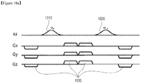
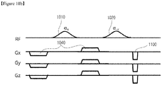
- FIGS. 10a to 10c show preparation pulse sequences used in the imaging method using double off resonance RF pulses according to exemplary embodiments of the present invention, in which a combination of gradient magnetic fields are used in applying a basic principle of the double off resonance RF pulse.
- values and signs of the gradient magnetic fields are adjusted so that the sum thereof over time becomes 0.
Landscapes
- Physics & Mathematics (AREA)
- Health & Medical Sciences (AREA)
- High Energy & Nuclear Physics (AREA)
- General Physics & Mathematics (AREA)
- Condensed Matter Physics & Semiconductors (AREA)
- Engineering & Computer Science (AREA)
- Nuclear Medicine, Radiotherapy & Molecular Imaging (AREA)
- Signal Processing (AREA)
- General Health & Medical Sciences (AREA)
- Radiology & Medical Imaging (AREA)
- Life Sciences & Earth Sciences (AREA)
- Biophysics (AREA)
- Molecular Biology (AREA)
- Surgery (AREA)
- Animal Behavior & Ethology (AREA)
- Medical Informatics (AREA)
- Public Health (AREA)
- Veterinary Medicine (AREA)
- Heart & Thoracic Surgery (AREA)
- Biomedical Technology (AREA)
- Pathology (AREA)
- Magnetic Resonance Imaging Apparatus (AREA)
- Spectroscopy & Molecular Physics (AREA)
- Optics & Photonics (AREA)
Description
- The present invention relates to a magnetic resonance method implemented in a magnetic resonance imaging (MRI) system, and more particularly, to an off resonance imaging method that is capable of canceling artifacts generated by being sensitive to the inhomogeneity of a main magnetic field and is capable of canceling undesired signals generated by an off resonance RF pulse in the case of simultaneously using the off resonance RF pulse and a spatial pre-saturation RF pulse in fat saturation (suppression), magnetization transfer, and chemical exchange saturation transfer methods using the off resonance radio frequency (RF) pulse in an MRI system.
- There are various types of image diagnosis devices such as an X-ray device, a computed tomography (CT) device, an ultrasonic device, an RI image device, an MRI device, and the like. Among them, the MRI device is a very important measuring device in a clinical practice since it is not harmful to the human body, as compared with other image diagnosis devices, and images characteristics of structural materials in the human body.
- The MRI device may obtain tissue parameters such as spin density, T1, T2, a chemical shift, magnetization transfer, chemical exchange saturation transfer, hematocele, spectroscopy, and the like, which are unique information on a living body, and may obtain various biological images through these parameters. However, it is quite difficult for the MRI device to obtain images with fat and water accurately separated from each other since the fat and the water coexist in living body tissue. The fat and the water cause relaxation time differences of T1 and T2, and artifacts are generated due to an inappropriate contrast or a chemical shift in the existing MRI imaging method depending on sensitivity of an MRI signal. Particularly, since a chemical shift phenomenon is present due to fat and water components, a detailed anatomical form cannot be obtained of a marginal zone in a structure enclosed by the fat.
- In order to solve this problem, a method of selectively exciting the fat and the water using a frequency selective radio frequency (RF) pulse is most generally used.
-
FIGS. 1 and2 are views describing a principle of a fat saturation (suppression) method using an off resonance RF pulse. - A unit of a chemical shift is represented by ppm (parts per million) and is measured as a relative numeral value. Since a water molecule has a chemical shift of 4.7ppm and the fat molecule has a chemical shift of 1.2ppm, the water molecule and the fat molecule have a difference of 3.5ppm (See
FIG. 1 ). In this case, when an external magnetic field is 1.5 Tesla (a resonance frequency 64MHz), a frequency difference of 220MHz corresponding to f=(64MHz)∗(3.5ppm) occurs. That is, 1H of the water molecule has a larger chemical shift and undergoes a minimum effective magnetic field larger than that of 1H of the fat molecule, such that it has a high frequency. - A chemical shift selective imaging sequence (CHESS) method is a method of unilaterally suppressing a signal of any specific frequency using the RF pulse. Since the RF pulse used in this method has only the specific frequency of a measurement tissue, the frequency RF pulse is given to selectively excite only the water or fat, thereby allowing a signal having only one component to be obtained.
- The CHESS method of selectively applying a saturation RF pulse that is in accordance with the resonance frequency of the fat will be described with reference to
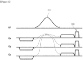
FIG. 2 . When magnetization of the water or the fat is selectively excited to be put on an X-Y plane, a spoiler gradient is applied to disperse an X-Y component of the magnetization of the fat, thereby canceling the magnetization signal of the fat effectively. Since the next imaging RF pulse has an influence on only the magnetization signal of the water, only the magnetization signal of the water is generated in the obtained image. -
FIG. 3 shows a preparation pulse sequence generally used in a fat suppression method. As shown inFIG. 3 , anRF pulse 310 of a very small frequency band is applied in order to selectively excite the fat, and arewinder 320 and aspoiler 330 gradients are used in order for phase recovery and fat magnetization dispersion. - However, in the fat suppression method, the degree of fat suppression may appear differently due to inhomogeneity of a main magnetic field (B0) at a local portion, and inhomogeneous fat saturation may be caused at the time of performing a test in a zone that is out of the center of the main magnetic field.
- A Dixon method is used as another solution, which is a method of suppressing the fat by obtaining two different images using a phase by a processional motion frequency difference between the water and the fat molecules and performing addition and subtraction on the two images, and requires a long period of time due to a post-processing process of reconfiguring the two images. In addition, also in this method, the degree of fat suppression appears differently due to the inhomogeneity of the main magnetic field. Therefore, existing fat saturation methods have a large limitation in obtaining a homogenous image.
- A basic principle of an iterative decomposition of water and fat with the echo asymmetry and least squares estimation (IDEAL) method is to mainly separate signals from each other by the phase difference between fat and water signals. In this method, which converts the 2-point Dixon method that has been conventionally used into a 3-point method, the respective echoes in three different phases (water-fat phase shifts -π/6, π/2, and 7π/6) is obtained using a phase difference depending on a difference in a resonance frequency between the fat and the water, and the fat signal and the water signal are separated from each other by a reconfiguration algorithm based on the echoes to generate independent water and fat suppression images. That is, the respective echoes are obtained in three different phases per time echo (TE), and four images such as a water-only image, a fat-only image, an in-phase image, and an out-of-phase image are reconfigured by the reconfiguration algorithm based on the respective echoes. In the IDEAL method, the images are reconfigured based on the signals obtained by performing excitation three times, such that a signal-to-noise ratio is increased. However, in the IDEAL method, test time and reconfiguration time of the images are higher, compared with the existing fat saturation method. Further, since the IDEAL method is also based on the Dixon method, the degree of fat suppression in each region of the human body appears differently due to the inhomogeneity of the main magnetic field.
- Magnetization transfer (MT) refers to the transfer of longitudinal magnetization from the hydrogen nuclei of water that has restricted motion to the hydrogen nuclei of water that moves with many degrees of freedom. The water with restricted motion is generally conceived as being bound to macromolecules through a series of hydrogen bonds. Saturated bound spins are excited using the off resonance RF pulse having a small frequency band so as to exchange energy by an interaction with free water spins. An effect of the magnetization transfer may be used to distinguish the articular cartilage, an adjacent joint liquid, synovia in which an inflammation is present, and the like. A physical model for the magnetization transfer as described above may be evaluated as a technical development using an advantage of a magnetization transfer contrast (MTC) image. The magnetization transfer contrast (MTC) image is an image with an increased contrast obtained by radiating the off resonance RF pulse having a continuous wave motion to saturate the resonance RF pulse in a partially restricted pool (See
FIG. 4 ). -
FIG. 5 shows examples of an RF pulse and gradient magnetic fields generally used in magnetization transfer. An offresonance RF pulse 510 having a small frequency band andspoiler gradients 530 are used, and charges of thespoiler gradients 530, magnitudes of thespoiler gradients 530, and axes on which thespoiler gradients 530 are applied are determined by an experimental value. However, generally, the influence of the spoiler gradient in imaging methods used in the magnetization transfer is not significant. - Since the off resonance RF pulse is also used in the magnetization transfer method, a post-processing process for artifacts generated due to the inhomogeneity of the main magnetic field is required.
- A new technology known as chemical exchange saturation transfer (CEST) may provide a significant new tool for MR molecular imaging. CEST exploits the ability of Nuclear Magnetic Resonance (NMR) to resolve different signals arising from protons on different molecules. By selectively saturating a particular proton signal (associated with a particular molecule or CEST agent) that is in exchange with surrounding water molecules, the MRI signal from the surrounding bulk water molecules is also attenuated. Images obtained with and without the RF saturating pulse reveal the location of the CEST agent. The chemical exchange must be in the intermediate regime where exchange is fast enough to efficiently saturate the bulk water signal but slow enough that there is a chemical shift difference between the exchangeable proton and the water proton resonances. The magnitude of the CEST effect therefore depends on both the exchange rate and the number of exchangeable protons.
- The CEST method has advantages over traditional molecular imaging techniques. The image contrast is controlled with radio-frequency (RF) pulses and can be turned on/off at will. The endogenous molecules of interest, in some cases, can be directly detected, eliminating the need for contrast agent to be delivered to, and to specifically react with, the molecule of interest.
- Referring to
FIG. 6 , it may be seen that the magnetization transfer imaging method is used twice in the CEST imaging method. Two off resonance RF pulses having a small frequency band are used in frequencies having opposite signs to obtain the signals. The saturated bound spins are excited in the respective frequencies to exchange energy by an interaction with free water spins, and the chemical transfer amount can be calculated based on the ratio between these signals. - In the CEST method, as shown in
FIG. 7 , anRF pulse 710 andspoiler gradients 730 are used, and signs of thespoiler gradients 730, magnitudes of thespoiler gradients 730, and the axes on which thespoiler gradients 730 are used are determined by an experimental value. However, generally, the influence of the spoiler gradient used in the CEST method is not significant, similarly to the influence of the spoiler gradient in the imaging method used in the magnetization transfer. - In addition, since the magnetization transfer method is used in the CEST method, the off resonance RF pulse should be used. When the off resonance RF pulse is used, the post-processing process of canceling artifacts generated due to the inhomogeneity of the main magnetic field is required.
-
FIG. 8 shows a pulse sequence used in an imaging method using an off-resonance RF pulse and a pre-saturation RF pulse. - In this imaging method, as shown in
FIG. 8 , thepre-saturation RF pulse 805 is used before the offresonance RF pulse 810 is applied. Here, since spins excited by thepre-saturation RF pulse 805 are excited by the offresonance RF pulse 810 once again, signals are returned, such that there occurs a phenomenon wherein undesired signals overlap with the ultimately-obtained signals. This phenomenon occurs in the case in which a frequency present within a frequency bandwidth of the pre-saturation RF pulse is excited using the off resonance RF pulse. - In the fat saturation imaging method, the magnetization transfer imaging method, and the CEST imaging method, the frequency bandwidth is narrow, and the excited frequency changes depending on the frequency of the free water proton and magnitude of the main magnetic field. However, in most cases, since the frequency present in the frequency bandwidth of the pre-saturation RF pulse is excited using the off resonance RF pulse, a problem occurs due to an interference signal by the pre-saturation RF pulse.
- The CEST method has advantages as compared with traditional molecule imaging technology. The image contrast can be adjusted or controlled depending on a high frequency applied from the outside. An endogenous molecule of interest may be directly detected without use of a contrast media reacting to the endogenous molecule of interest. However, since the magnetization transfer method is also used in the CEST method, the off resonance RF pulse should be used. When the off resonance RF pulse is used as described above, the post-processing process of canceling artifacts generated due to the inhomogeneity of the main magnetic field is required.
- Recently, methods of implementing the CEST method using a spin-lock method have been suggested and have been used in an image emphasizing Tlrho value used in muscular skeletal disease. However, since three off resonance RF pulses are used in the spin-lock method, there is a problem that the specific absorption rate (SAR) value is increased, which is a measure of the rate of energy absorption in a living body.
-
US 2009/0009168 A1 discloses infigure 4 a method for simultaneously compensating for external and radiofrequency (RF) magnetic-field inhomogeneities in an MRI system, comprising applying a first RF pulse with an arbitrary excitation flip angle followed by two off-resonance-spin-lock pulses, whereby the second off-resonance-spin-lock pulse has an inverse phase and frequency from the first off-resonance-spin-lock pulse in order to refocus (or unwind) the detrimental effects of RF field inhomogeneity, and then a second RF pulse with an excitation flip angle inverse to the arbitrary excitation flip angle of the first RF pulse is applied. - An aspect of the present invention provides a magnetic resonance method, capable of solving problems occurring in conventional magnetic resonance methods, for getting an image of the whole body of a human being by using off resonance radio frequency (RF) pulses.
- Another aspect of the present invention provides fat saturation (suppression), magnetization transfer, and chemical exchange saturation transfer methods that are not sensitive to the inhomogeneity of a main magnetic field.
- Still another aspect of the present invention provides a method of canceling undesired signals appearing again due to an off resonance RF pulse in magnetic resonance methods simultaneously using the off resonance RF pulse and a spatial pre-saturation RF pulse.
- In order to solve the above-mentioned objects, a first off resonance RF pulse and a second off resonance RF pulse having a phase difference of 180 degrees from the first off resonance RF pulse are applied, and a plurality of auxiliary gradient magnetic fields for offsetting the inhomogeneity of a main magnetic field generated due to the application of the first and second off resonance RF pulses are added.
- According to one aspect of the present invention, there is provided a magnetic resonance method through an MRI system, for cancelling undesired signals generated by a first off resonance RF pulse of a preparation pulse sequence, as defined in
independent claim 1, the method including: applying a first off resonance RF pulse; applying a second off resonance RF pulse for offsetting the inhomogeneity of a main magnetic field generated due to the first off resonance RF pulse; and applying a plurality of auxiliary gradient magnetic fields offsetting the inhomogeneity of the main magnetic field generated by applying the first and second off resonance RF pulses, wherein the application of the plurality of auxiliary gradient magnetic fields includes: adjusting values and signs of each of the plurality of auxiliary gradient magnetic fields, such that the sum over time of the plurality of auxiliary gradient magnetic fields becomes 0. - In the changing of the signs of each of the plurality of auxiliary gradient magnetic fields, the sign of a first auxiliary gradient magnetic field of the plurality of auxiliary gradient magnetic fields may be positive (+) or negative (-).
- The magnetic resonance method may further include applying spoiler gradient magnetic fields, together with the applying of the auxiliary gradient magnetic fields.
- The auxiliary gradient magnetic fields may be applied at at least one of the points in time of: before the application of the first off resonance RF pulse; after the application of the first off resonance RF pulse and before the application of the second off resonance RF pulse; and after the application of the second off resonance RF pulse. According to the invention, at least one auxiliary gradient magnetic field is applied before the application of the first off resonance RF pulse, and at least one auxiliary gradient magnetic field is applied between the application of the first off resonance RF pulse and the application of the second off resonance RF pulse.
- The second off resonance RF pulse has a phase difference of 180 degrees from the first off resonance RF pulse.
- The magnetic resonance method may further include, after the application of the plurality of auxiliary gradient magnetic fields, applying a pulse sequence for using at least one of a fat saturation method, a magnetization transfer method, Tlrho imaging method, and a chemical exchange saturation transfer method.
- The magnetic resonance method may further include, before the applying of the first off resonance RF pulse, applying a spatial pre-saturation RF pulse.
- When an MRI image is obtained by the magnetic resonance method using the first and second off resonance RF pulses and the gradient magnetic fields according to an exemplary embodiment of the present invention, artifacts generated due to the inhomogeneity of a main magnetic field in a magnetic resonance method using an off resonance RF pulse may be removed. In addition, if the magnetic resonance method according to an exemplary embodiment of the present invention is applied to magnetic resonance method using a spatial pre-saturation RF pulse, the phenomenon may be removed wherein spins excited by the pre-saturation RF pulse are again excited by the off resonance RF pulse to return signals, such that undesired signals overlap and appear in an ultimately-obtained signal.
- As described above, since the artifacts generated due to the inhomogeneity of the main magnetic field may be canceled, a post-processing process is not required as in the related art, and a combination of the gradient magnetic fields rather than additional RF pulses is used in order to solve the inhomogeneity of the main magnetic field, thereby making it possible to decrease SAR values.
-
-
FIGS. 1 and2 are views describing a principle of a fat saturation (suppression) method using an off resonance RF pulse. -
FIG. 3 shows a preparation pulse sequence generally used in a fat suppression method. -
FIG. 4 is a view describing a principle of an imaging method of magnetization transfer using an off resonance RF pulse. -
FIG. 5 shows examples of an RF pulse and a gradient magnetic field generally used in magnetization transfer. -
FIGS. 6 and7 show a principle of an imaging method of chemical exchange saturation transfer using an off resonance RF pulse and examples of an RF pulse and a gradient magnetic field, respectively, that are generally used. -
FIG. 8 shows a pulse sequence used in an imaging method using an off-resonance RF pulse and a pre-saturation RF pulse. -
FIG. 9 is a view describing a principle of an imaging method using double off resonance RF pulses according to an example outside the scope of the present invention for canceling artifacts generated in general imaging methods using an off resonance RF pulse. -
FIGS. 10a to 10c show preparation pulse sequences used in the imaging method using double off resonance RF pulses according to exemplary embodiments of the present invention, in which a combination of gradient magnetic fields are used in applying a basic principle of the double off resonance RF pulse. -
FIG. 11 is a view showing an imaging method using double off resonance RF pulses according to an exemplary embodiment of the present invention for canceling artifacts generated in general imaging methods using an off resonance RF pulse and a pre-saturation RF pulse. -
FIGS. 12a and12b show preparation pulse sequences according to exemplary embodiments of the present invention for canceling undesired signals by applying gradient magnetic fields in an imaging method using an off resonance RF pulse and a pre-saturation RF pulse. -
FIG. 13 shows an example in which a pulse sequence including double off resonance RF pulses and a combination of gradient magnetic fields according to an exemplary embodiment of the present invention is applied to a fat saturation imaging method of an image acquisition of a shoulder region. - Hereinafter, an imaging method through a magnetic resonance imaging (MRI) system according to exemplary embodiments of the present invention will be described in detail with reference to the accompanying drawings. However, a detailed description for well-known functions and configurations that may obscure the gist of the present invention will be omitted.
- Since a configuration of the MRI system applied to the present invention is well-known, a description thereof will be omitted.
- Generally, among imaging methods using an off resonance radio frequency (RF) pulse, there are a fat saturation (suppression) method, a magnetization transfer method, and a chemical exchange saturation transfer method. In addition, a method using a pre-saturation RF pulse capable of decreasing signals of specific positions of an image by first locally exciting spins also uses an off resonance RF pulse.
- In the method as described above, artifacts are generated due to the inhomogeneity of a main magnetic field. In detail, phases of selectively excited spins are not constant due to the inhomogeneity of the main magnetic field caused by the use of the off resonance RF pulse, and signals obtained from the spins of the selected frequencies do not have the same phase due to this phase difference, such that the artifacts having an inhomogeneous form appear in a reconstructed image.
- In order to solve the problem of the artifacts as described above, double off resonance RF pulses are used in the present invention.
-
FIG. 9 is a view describing a principle of an imaging method using double off resonance RF pulses for canceling artifacts generated in general imaging methods using an off resonance RF pulse. - As shown in
FIG. 9 , after a first offresonance RF pulse 910 is applied, a second offresonance RF pulse 920 having an opposite phase, that is, a phase having a difference of 180 degrees, is applied. - In an imaging method using the off
resonance RF pulse 910, since theoff resonance pulse 910 is solely used without any gradient, the phase information of selectively excited spins is not constant due to the homogeneity of a main magnetic field. Due to this phase difference, signals obtained from the spins of the selected frequencies do not have the same phase, such that artifacts having an inhomogeneous form appear in a reconstructed image. - As a method of compensating for this phase difference, there is a method of applying additional gradient magnetic filed.
- However, since the off
resonance RF pulse 910 does not have a selective gradient magnetic field applied simultaneously therewith, and may be considered as being affected by only a small amount of gradient magnetic field due to the inhomogeneity of the main magnetic field, such a distorted phase may not be compensated for. In addition, since theoff resonance pulse 910 uses a principle of selecting and exciting a frequency with respect to an entire volume without using a selective gradient magnetic field, another offresonance RF pulse 920 that is the same as the offresonance RF pulse 910 should be used in order to correct the phase. Here, the other offresonance RF pulse 920 has a phase difference of 180 degrees from the offresonance RF pulse 910 in order to return the phase distorted due to the inhomogeneity of the main magnetic field to the original phase, thereby making it possible to correct the phase. -
FIGS. 10a to 10c show preparation pulse sequences used in the imaging method using double off resonance RF pulses according to exemplary embodiments of the present invention, in which a combination of gradient magnetic fields are used in applying a basic principle of the double off resonance RF pulse. - When two sequential RF pulses are applied, the phase is corrected by the off resonance RF pulses. However, all spins should be again magnetized longitudinally before adding imaging techniques of subsequently applying magnetic fields. As a method of canceling these residual spins, additional gradient magnetic fields are applied in an exemplary embodiment of the present invention.
- In this case, unlike a method according to the related art, a combination of rewinder and spoiler gradient magnetic field is optimized, thereby making it possible to minimize the increase of time necessary for the application of double off resonance RF pulses.
- That is, in the imaging method using double off resonance RF pulses according to an exemplary embodiment of the present invention, the first off resonance RF pulse is applied, the second off resonance RF pulse for offsetting the inhomogeneity of the main magnetic field generated due to the first off resonance RF pulse is applied, and a plurality of auxiliary gradient magnetic fields for offsetting the inhomogeneity of the main magnetic field generated by applying the first and second off resonance RF pulses are applied. Here, in applying the auxiliary gradient magnetic fields, a combination of the auxiliary gradient magnetic fields is adjusted and signs thereof are changed to obtain an optimal combination of auxiliary gradient magnetic fields.
- As the optimal combination of the auxiliary gradient magnetic fields, the combination and the signs of the auxiliary gradient magnetic fields are 2. adjusted so that the sum over time of one or more applied auxiliary gradient magnetic fields becomes 0.
- Polarities of the auxiliary gradient magnetic fields may start from a positive (+) polarity or start from a negative (-) polarity. For example, various combinations such as (+, -, -, +), (-, +, +, -), (+, 0, 0, -), (-, 0, 0, +), and the like, are possible.
- Pulse sequences in the imaging method according to an exemplary embodiments of the present invention are shown in
FIGS. 10a to 10c . - As shown in
FIG. 10a , in a double off resonance RF pulse applying method of applying a first offresonance RF pulse 1010 and a second offresonance RF pulse 1020 having a phase difference of 180 degrees from the first offresonance RF pulse 1010, gradientmagnetic fields 1030 are applied before applying the first offresonance RF pulse 1010, between the first and second offresonance RF pulses resonance RF pulse 1020. - The
gradients 1030 may be equally applied with respect to x, y, and z axes, and values and signs thereof are adjusted so that the sum thereof over time becomes 0. - According to another exemplary embodiment of the present invention, as shown in
FIG. 10b ,gradients 1040 may be applied before applying the first offresonance RF pulse 1010 and between the first and second offresonance RF pulses spoiler gradient 1100 may be applied after applying the secondresonance RF pulse 1020. - Also in this case, the
gradients 1040 may be equally applied with respect to x, y, and z axes, and values and signs thereof are adjusted so that the sum thereof over time becomes 0. - According to still another exemplary embodiment of the present invention, as shown in
FIG. 10c ,gradients 1050 may be applied before applying the first offresonance RF pulse 1010, between the first and second offresonance RF pulses resonance RF pulse 1020, andspoiler gradient 1100 may be then applied. - Also in this case, the
gradients 1050 may be equally applied with respect to x, y, and z axes, and values and signs thereof are adjusted so that the sum thereof over time becomes 0. - Meanwhile, frequency bandwidths, central frequencies, and pulse forms of the first and second off resonance RF pulses may be adjusted, if necessary. For example, in the case of using a fat saturation method, the width of the off resonance RF pulse is relatively large; however, in the case of using a magnetization transfer or CEST method, an off resonance RF pulse having a narrower width compared with that of the fat saturation method is used. That is, the frequency bandwidths, the central frequencies, and the pulse forms of the first and second off resonance RF pulses may be appropriately selected depending on a used imaging method, and is not particularly limited in the present invention.
- Since an image without artifacts due to the inhomogeneity of the main magnetic field is obtained by using the first and second off resonance RF pulses and the combination of the gradients as described above, a post-processing process for compensating for the inhomogeneity of the main magnetic field or acquisition of an additional image for the post-processing as in the related art is not required.
- In addition, the imaging method according to an exemplary embodiment of the present invention, that solves problems related to the inhomogeneity of the main magnetic field by using the combination of the gradient magnetic fields while using the first and second off resonance RF pulses, may more reliably solve problems related to the inhomogeneity of the main magnetic field and decrease the number of RF pulses as compared with a spin lock method of applying a third RF pulse, thereby making it possible to decrease a specific absorption rate (SAR) value, which is an index of a radio wave absorption rate of the living body.
-
FIG. 11 is a view showing an exemplary embodiment of the present invention for removing a phenomenon that spins excited by a pre-saturation RF pulse are excited once again by the off resonance RF pulse to return signals, such that undesired signals are overlapped with and appear in a finally obtained signal in general imaging methods using the off resonance RF pulse and the pre-saturation RF pulse. - As shown in
FIGS. 11 , two offresonance RF pulses pre-saturation RF pulse 1105. - Here, similar to exemplary embodiments described above with reference to
FIGS. 10a to 10c , appropriately combined gradient magnetic fields are applied, thereby making it possible to minimize undesired signals. -
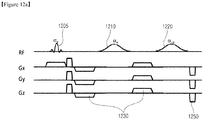
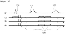
FIGS. 12a and12b show preparation pulse sequences according to exemplary embodiments of the present invention for canceling undesired signals by applying gradient magnetic fields in an imaging method using an off resonance RF pulse and a pre-saturation RF pulse. - First, as shown in
FIG. 12a , gradientmagnetic fields 1230 are applied after applying apre-saturation RF pulse 1205 and before applying a first offresonance RF pulse 1210 and are applied between first and second offresonance RF pulses spoiler gradient 1250 may be applied after applying the second offresonance RF pulse 1220. - In addition, in another exemplary embodiment of the present invention shown in
FIG. 12b , gradientmagnetic fields 1240 are applied after applying apre-saturation RF pulse 1205 and before applying a first offresonance RF pulse 1210, are applied between first and second offresonance RF pulses resonance RF pulse 1220. - In both of two exemplary embodiments shown in
FIGS. 12a and12b , values and signs of the gradient magnetic fields are adjusted so that the sum thereof over time becomes 0. -
FIG. 13 shows an example in which a pulse sequence including double off resonance RF pulses and a combination of gradient magnetic fields according to an exemplary embodiment of the present invention is applied to to a fat saturation imaging method of an image acquisition of a shoulder region. InFIG. 13 , the pulse sequence shown inFIG. 10a has been used. - In
FIG. 13 , on the left side are images obtained without fat saturation, at the center are images obtained using a single off resonance RF pulse imaging method currently clinically used, and on the right side are images obtained using double off resonance RF pulses and the combination of the gradient magnetic fields according to an exemplary embodiment of the present invention. The images obtained using a single off resonance RF pulse have a fat saturation effect greater than that of the imaging method using double off resonance RF pulses, but include artifacts generated due to the inhomogeneity of the main magnetic field, as compared with those of the reference image (center). - On the other hand, it may be appreciated that the double off resonance RF pulse imaging method according to an exemplary embodiment of the present invention does not include artifacts at all and accomplishes homogeneous fat saturation, which indicates an improved result.
- Magnetic resonance imaging method using double off resonance RF pulse according to the embodiments of the present invention can be applied to fat saturation method, a magnetization transfer method, Tlrho imaging method, and a chemical exchange saturation transfer method.
- Although the preferred embodiments of the present invention have been disclosed for illustrative purposes, those skilled in the art will appreciate that various modifications, additions and substitutions are possible, without departing from the scope of the invention as defined in the accompanying claims.
Claims (6)
- A magnetic resonance method using an MRI system, for cancelling undesired signals generated by a first off resonance RF pulse of a preparation pulse sequence, said method comprising:applying the first off resonance radio frequency (RF) pulse (910, 1010, 1110, 1210) for selectively exciting undesired signals;applying a second off resonance RF pulse (920, 1020, 1120, 1220) Z for offsetting the inhomogeneity of a main magnetic field generated due to the first off resonance RF pulse, the second off resonance RF pulse having a phase difference of 180 degrees from the first off resonance RF pulse; andapplying a plurality of auxiliary gradient magnetic fields (940, 1030, 1040, 1050, 1140, 1230, 1240) for offsetting the inhomogeneity of the main magnetic field due to the first and second off resonance RF pulses,wherein the application of the plurality of auxiliary gradient magnetic fields includes:adjusting values and signs of each of the plurality of auxiliary gradient magnetic fields, such that the sum over time of the plurality of auxiliary gradient magnetic fields becomeswherein at least one auxiliary gradient magnetic field is applied before the application of the first off resonance RF pulse, and at least one auxiliary gradient magnetic field is applied between the application of the first off resonance RF pulse and the application of the second off resonance RF pulse.
- The magnetic resonance method of claim 1, wherein in the adjusting the signs of the plurality of auxiliary gradient magnetic fields, the sign of a first auxiliary gradient magnetic field of the plurality of auxiliary gradient magnetic fields is positive (+).
- The magnetic resonance method of claim 1, wherein in the adjusting of the signs of the plurality auxiliary gradient magnetic fields, the sign of a first auxiliary gradient magnetic field of the plurality of (-).auxiliary gradient magnetic fields is negative
- The magnetic resonance method of claim 1, further comprising applying spoiler gradient magnetic fields (1100, 1250).
- The magnetic resonance method of claim 1 further comprising, after the application of the plurality of auxiliary gradient magnetic fields, applying a pulse sequence of at least one of a fat saturation method, a magnetization transfer method, T1 rho imaging method, and a chemical exchange saturation transfer method.
- The magnetic resonance method of claim 1, further comprising, before the application of the first off resonance RF pulse, applying a spatial pre-saturation RF pulse.
Applications Claiming Priority (2)
| Application Number | Priority Date | Filing Date | Title |
|---|---|---|---|
| KR1020130167785A KR101560463B1 (en) | 2013-12-30 | 2013-12-30 | Magnetic resonance imaging method cancelling artifacts and undesired signals |
| PCT/KR2014/004765 WO2015102169A1 (en) | 2013-12-30 | 2014-05-28 | Magnetic resonance imaging method canceling artifacts and undesired signals |
Publications (3)
| Publication Number | Publication Date |
|---|---|
| EP3089663A1 EP3089663A1 (en) | 2016-11-09 |
| EP3089663A4 EP3089663A4 (en) | 2018-01-03 |
| EP3089663B1 true EP3089663B1 (en) | 2021-11-17 |
Family
ID=53493501
Family Applications (1)
| Application Number | Title | Priority Date | Filing Date |
|---|---|---|---|
| EP14846738.4A Active EP3089663B1 (en) | 2013-12-30 | 2014-05-28 | Magnetic resonance imaging method for canceling artifacts and undesired signals |
Country Status (5)
| Country | Link |
|---|---|
| US (1) | US9606211B2 (en) |
| EP (1) | EP3089663B1 (en) |
| JP (1) | JP6181208B2 (en) |
| KR (1) | KR101560463B1 (en) |
| WO (1) | WO2015102169A1 (en) |
Families Citing this family (12)
| Publication number | Priority date | Publication date | Assignee | Title |
|---|---|---|---|---|
| US10126402B2 (en) * | 2015-06-02 | 2018-11-13 | Case Western Reserve University | Magnetic resonance imaging (MRI) with artifact-free T2 mapping |
| KR101877104B1 (en) * | 2015-12-11 | 2018-07-10 | (의료)길의료재단 | Water suppression method using control of central frequency of excitation signal band and control of receiver bandwidth in magnetic resonance spectroscopy |
| EP3236277B1 (en) | 2016-04-18 | 2021-12-01 | Centre Hospitalier Universitaire Vaudois (CHUV) | Differentiated tissue excitation by mri using binomial off-resonance 1-1 rf pulses |
| US11415655B2 (en) * | 2016-05-27 | 2022-08-16 | University Of Virginia Patent Foundation | Reduced field-of-view perfusion imaging with high spatiotemporal resolution |
| GB201705577D0 (en) | 2017-04-06 | 2017-05-24 | King's College London | Controlled excitiation and saturation of magnetization transfer systems |
| EP3330728B1 (en) * | 2017-05-22 | 2020-10-21 | Siemens Healthcare GmbH | Method for vascular imaging with the aid of an mr equipment |
| KR101949491B1 (en) | 2017-05-29 | 2019-02-18 | 성균관대학교산학협력단 | Device and method for generating magnetic resonance imaging |
| US10684343B2 (en) * | 2017-05-31 | 2020-06-16 | Canon Medical Systems Corporation | Magnetic resonance imaging apparatus and magnetic resonance imaging method |
| US10598751B1 (en) * | 2019-02-04 | 2020-03-24 | The Chinese University Of Hong Kong | System and method for separation of water and fat signals during spin-lock magnetic resonance imaging |
| CN111856360A (en) * | 2019-04-24 | 2020-10-30 | 通用电气精准医疗有限责任公司 | Method for acquiring magnetic resonance imaging data and magnetic resonance imaging system |
| WO2023022778A1 (en) * | 2021-08-18 | 2023-02-23 | University Of Pittsburgh-Of The Commonwealth System Of Higher Education | Chemical exchange saturation transfer (cest) magnetic resonance imaging using an asef or arose system |
| CN117547246B (en) * | 2024-01-12 | 2024-04-09 | 中国科学技术大学先进技术研究院 | Spatial signal saturation method, apparatus, device and computer readable storage medium |
Family Cites Families (24)
| Publication number | Priority date | Publication date | Assignee | Title |
|---|---|---|---|---|
| US5133357A (en) * | 1991-02-07 | 1992-07-28 | General Electric Company | Quantitative measurement of blood flow using cylindrically localized fourier velocity encoding |
| US5250898A (en) * | 1991-08-09 | 1993-10-05 | Board Of Trustees Of The Leland Stanford Junior University | Method and means for magnetic resonance imaging and spectroscopy using pulsed saturation transfer contrast |
| US5233298A (en) * | 1992-02-20 | 1993-08-03 | General Electric Company | Quantitative measurement of blood flow at multiple positions using comb excitation and fourier velocity encoding |
| WO1993018415A1 (en) * | 1992-03-09 | 1993-09-16 | University Of Washington | Image neurography and diffusion anisotropy imaging |
| US6384601B1 (en) * | 1998-04-06 | 2002-05-07 | The United States Of America As Represented By The Secretary Of Department Of Health & Human Services | Local magnetization spoiling using a gradient insert for reducing the field of view in magnetic resonance imaging |
| US6043656A (en) * | 1998-11-23 | 2000-03-28 | General Electric Company | Method for compensating an MRI system for residual magnetization |
| US6445184B1 (en) * | 2001-11-20 | 2002-09-03 | Koninklijke Philips Electronics N.V. | Multiple gradient echo type projection reconstruction sequence for MRI especially for diffusion weighted MRI |
| GB0211516D0 (en) * | 2002-05-20 | 2002-06-26 | Univ Sheffield | Method and apparatus for magnetic resonance imaging |
| EP1646885B1 (en) | 2003-07-11 | 2008-10-22 | Koninklijke Philips Electronics N.V. | Shimming of mri scanner involving fat suppression and/or black blood preparation |
| US7372267B2 (en) * | 2006-05-04 | 2008-05-13 | University Of Basel | Method and apparatus for generation of magnetization transfer contrast in steady state free precession magnetic resonance imaging |
| JP5398149B2 (en) | 2007-03-27 | 2014-01-29 | 株式会社東芝 | Magnetic resonance imaging system |
| US8369599B2 (en) * | 2007-05-17 | 2013-02-05 | University Of Washington | Fast two-point mapping of the bound pool fraction and cross-relaxation rate constant for MRI |
| US7705596B2 (en) * | 2007-05-18 | 2010-04-27 | The Trustees Of The University Of Pennsylvania | System and method for minimizing MRI-imaging artifacts |
| WO2009061468A1 (en) | 2007-11-07 | 2009-05-14 | Oni Medical Systems, Inc. | Systems, methods and machine readable programs for enhanced fat/water separation in magnetic resonance imaging |
| US20090143672A1 (en) * | 2007-12-04 | 2009-06-04 | Harms Steven E | Method for mapping image reference points to facilitate biopsy using magnetic resonance imaging |
| US8278925B2 (en) * | 2008-03-26 | 2012-10-02 | The General Hospital Corporation | Method for relaxation-compensated fast multi-slice chemical exchange saturation transfer MRI |
| JP5416960B2 (en) * | 2008-12-17 | 2014-02-12 | 株式会社東芝 | Magnetic resonance imaging system |
| US8502538B2 (en) * | 2009-03-19 | 2013-08-06 | Kabushiki Kaisha Toshiba | B1 and/or B0 mapping in MRI system using k-space spatial frequency domain filtering with complex pixel by pixel off-resonance phase in the B0 map |
| US8077955B2 (en) * | 2009-03-19 | 2011-12-13 | Kabushiki Kaisha Toshiba | B1 mapping in MRI system using k-space spatial frequency domain filtering |
| WO2010114608A1 (en) | 2009-04-02 | 2010-10-07 | Regents Of The University Of Minnesota | Mp-swift with adiabatic inversion preparation |
| US8198891B2 (en) * | 2009-06-15 | 2012-06-12 | General Electric Company | System, method, and apparatus for magnetic resonance RF-field measurement |
| US8248070B1 (en) | 2011-03-22 | 2012-08-21 | Kabushiki Kaisha Toshiba | MRI using prep scan sequence producing phase-offset NMR signals from different NMR species |
| US8866478B2 (en) * | 2011-07-13 | 2014-10-21 | Siemens Aktiengesellschaft | Method and processor and magnetic resonance apparatus for designing RF pulses to mitigate off-resonance effects |
| JP5917077B2 (en) * | 2011-10-13 | 2016-05-11 | 株式会社東芝 | Magnetic resonance imaging system |
-
2013
- 2013-12-30 KR KR1020130167785A patent/KR101560463B1/en active IP Right Grant
-
2014
- 2014-05-28 EP EP14846738.4A patent/EP3089663B1/en active Active
- 2014-05-28 WO PCT/KR2014/004765 patent/WO2015102169A1/en active Application Filing
- 2014-05-28 US US14/432,211 patent/US9606211B2/en active Active
- 2014-05-28 JP JP2015555940A patent/JP6181208B2/en active Active
Also Published As
| Publication number | Publication date |
|---|---|
| US9606211B2 (en) | 2017-03-28 |
| JP2016504958A (en) | 2016-02-18 |
| WO2015102169A1 (en) | 2015-07-09 |
| US20160154081A1 (en) | 2016-06-02 |
| KR101560463B1 (en) | 2015-10-16 |
| EP3089663A1 (en) | 2016-11-09 |
| EP3089663A4 (en) | 2018-01-03 |
| JP6181208B2 (en) | 2017-08-16 |
| KR20150080184A (en) | 2015-07-09 |
Similar Documents
| Publication | Publication Date | Title |
|---|---|---|
| EP3089663B1 (en) | Magnetic resonance imaging method for canceling artifacts and undesired signals | |
| Soher et al. | A review of MR physics: 3T versus 1.5 T | |
| Witschey II et al. | Artifacts in T1ρ-weighted imaging: Compensation for B1 and B0 field imperfections | |
| US8723516B2 (en) | B1-robust and T1-robust species suppression in MRI | |
| US20120025826A1 (en) | Method For Reducing Artifacts In Magnetic Resonance Imaging | |
| Scott et al. | Rotating frame RF current density imaging | |
| Alonso-Ortiz et al. | Impact of magnetic susceptibility anisotropy at 3 T and 7 T on T2*-based myelin water fraction imaging | |
| US10247798B2 (en) | Simultaneous multi-slice MRI measurement | |
| EP3236277B1 (en) | Differentiated tissue excitation by mri using binomial off-resonance 1-1 rf pulses | |
| US20060220643A1 (en) | MR method for minimizing the chemical shift artifact, using a localized spatially dependent saturation pulse | |
| Huang et al. | Improving MRI differentiation of gray and white matter in epileptogenic lesions based on nonlinear feedback | |
| Boulant | T1 and T2 effects during radio-frequency pulses in spoiled gradient echo sequences | |
| Kangarlu et al. | Human rapid acquisition with relaxation enhancement imaging at 8 T without specific absorption rate violation | |
| Farkash et al. | Sculpting 3D spatial selectivity with pairs of 2D pulses: A comparison of methods | |
| Kim et al. | Friend or Foe: How to Suppress and Measure Fat During Abdominal Resonance Imaging? | |
| Meacham | The MRI study guide for technologists | |
| Fritz et al. | MESMERISED: Super-accelerated 7 T STEAM imaging for quantitative multi-contrast and diffusion MRI | |
| Gulani et al. | Improved time efficiency and accuracy in diffusion tensor microimaging with multiple-echo acquisition | |
| Gürler | Multichannel and Phase Based Magnetic Resonance Electrical Properties Tomography | |
| He | Application of Parallel Transmission to Ultra-High Field Magnetic Resonance Spectroscopy and Imaging | |
| Norbeck | Development of Radiofrequency Pulses for Fast and Motion-robust Brain MRI | |
| Malik et al. | High-resolution T1-, T2-, and T2*-weighted anatomical imaging | |
| Liao | Development and application of electrical conductivity mapping using magnetic resonance imaging | |
| Yu | Extending the Scope of Magnetic Resonance Fingerprinting | |
| Chan | Disentangling a Cube: Imaging White Matter with Advanced MRI Techniques |
Legal Events
| Date | Code | Title | Description |
|---|---|---|---|
| PUAI | Public reference made under article 153(3) epc to a published international application that has entered the european phase |
Free format text: ORIGINAL CODE: 0009012 |
|
| STAA | Information on the status of an ep patent application or granted ep patent |
Free format text: STATUS: REQUEST FOR EXAMINATION WAS MADE |
|
| 17P | Request for examination filed |
Effective date: 20150401 |
|
| AK | Designated contracting states |
Kind code of ref document: A1 Designated state(s): AL AT BE BG CH CY CZ DE DK EE ES FI FR GB GR HR HU IE IS IT LI LT LU LV MC MK MT NL NO PL PT RO RS SE SI SK SM TR |
|
| AX | Request for extension of the european patent |
Extension state: BA ME |
|
| DAX | Request for extension of the european patent (deleted) | ||
| A4 | Supplementary search report drawn up and despatched |
Effective date: 20171130 |
|
| RIC1 | Information provided on ipc code assigned before grant |
Ipc: G01R 33/483 20060101ALN20171124BHEP Ipc: G01R 33/48 20060101ALN20171124BHEP Ipc: G01R 33/54 20060101ALI20171124BHEP Ipc: G01R 33/56 20060101ALN20171124BHEP Ipc: G01R 33/485 20060101ALN20171124BHEP Ipc: G01R 33/565 20060101AFI20171124BHEP |
|
| REG | Reference to a national code |
Ref country code: DE Ref legal event code: R079 Ref document number: 602014081345 Country of ref document: DE Free format text: PREVIOUS MAIN CLASS: A61B0005055000 Ipc: G01R0033565000 |
|
| GRAP | Despatch of communication of intention to grant a patent |
Free format text: ORIGINAL CODE: EPIDOSNIGR1 |
|
| STAA | Information on the status of an ep patent application or granted ep patent |
Free format text: STATUS: GRANT OF PATENT IS INTENDED |
|
| RIC1 | Information provided on ipc code assigned before grant |
Ipc: G01R 33/565 20060101AFI20210511BHEP Ipc: G01R 33/54 20060101ALI20210511BHEP Ipc: G01R 33/48 20060101ALN20210511BHEP Ipc: G01R 33/483 20060101ALN20210511BHEP Ipc: G01R 33/56 20060101ALN20210511BHEP Ipc: G01R 33/485 20060101ALN20210511BHEP |
|
| RIC1 | Information provided on ipc code assigned before grant |
Ipc: G01R 33/565 20060101AFI20210514BHEP Ipc: G01R 33/54 20060101ALI20210514BHEP Ipc: G01R 33/48 20060101ALN20210514BHEP Ipc: G01R 33/483 20060101ALN20210514BHEP Ipc: G01R 33/56 20060101ALN20210514BHEP Ipc: G01R 33/485 20060101ALN20210514BHEP |
|
| INTG | Intention to grant announced |
Effective date: 20210608 |
|
| GRAS | Grant fee paid |
Free format text: ORIGINAL CODE: EPIDOSNIGR3 |
|
| GRAA | (expected) grant |
Free format text: ORIGINAL CODE: 0009210 |
|
| STAA | Information on the status of an ep patent application or granted ep patent |
Free format text: STATUS: THE PATENT HAS BEEN GRANTED |
|
| AK | Designated contracting states |
Kind code of ref document: B1 Designated state(s): AL AT BE BG CH CY CZ DE DK EE ES FI FR GB GR HR HU IE IS IT LI LT LU LV MC MK MT NL NO PL PT RO RS SE SI SK SM TR |
|
| REG | Reference to a national code |
Ref country code: GB Ref legal event code: FG4D |
|
| REG | Reference to a national code |
Ref country code: DE Ref legal event code: R096 Ref document number: 602014081345 Country of ref document: DE |
|
| REG | Reference to a national code |
Ref country code: IE Ref legal event code: FG4D |
|
| REG | Reference to a national code |
Ref country code: AT Ref legal event code: REF Ref document number: 1448483 Country of ref document: AT Kind code of ref document: T Effective date: 20211215 |
|
| REG | Reference to a national code |
Ref country code: NL Ref legal event code: FP |
|
| REG | Reference to a national code |
Ref country code: LT Ref legal event code: MG9D |
|
| REG | Reference to a national code |
Ref country code: AT Ref legal event code: MK05 Ref document number: 1448483 Country of ref document: AT Kind code of ref document: T Effective date: 20211117 |
|
| PG25 | Lapsed in a contracting state [announced via postgrant information from national office to epo] |
Ref country code: RS Free format text: LAPSE BECAUSE OF FAILURE TO SUBMIT A TRANSLATION OF THE DESCRIPTION OR TO PAY THE FEE WITHIN THE PRESCRIBED TIME-LIMIT Effective date: 20211117 Ref country code: LT Free format text: LAPSE BECAUSE OF FAILURE TO SUBMIT A TRANSLATION OF THE DESCRIPTION OR TO PAY THE FEE WITHIN THE PRESCRIBED TIME-LIMIT Effective date: 20211117 Ref country code: FI Free format text: LAPSE BECAUSE OF FAILURE TO SUBMIT A TRANSLATION OF THE DESCRIPTION OR TO PAY THE FEE WITHIN THE PRESCRIBED TIME-LIMIT Effective date: 20211117 Ref country code: BG Free format text: LAPSE BECAUSE OF FAILURE TO SUBMIT A TRANSLATION OF THE DESCRIPTION OR TO PAY THE FEE WITHIN THE PRESCRIBED TIME-LIMIT Effective date: 20220217 Ref country code: AT Free format text: LAPSE BECAUSE OF FAILURE TO SUBMIT A TRANSLATION OF THE DESCRIPTION OR TO PAY THE FEE WITHIN THE PRESCRIBED TIME-LIMIT Effective date: 20211117 |
|
| PG25 | Lapsed in a contracting state [announced via postgrant information from national office to epo] |
Ref country code: IS Free format text: LAPSE BECAUSE OF FAILURE TO SUBMIT A TRANSLATION OF THE DESCRIPTION OR TO PAY THE FEE WITHIN THE PRESCRIBED TIME-LIMIT Effective date: 20220317 Ref country code: SE Free format text: LAPSE BECAUSE OF FAILURE TO SUBMIT A TRANSLATION OF THE DESCRIPTION OR TO PAY THE FEE WITHIN THE PRESCRIBED TIME-LIMIT Effective date: 20211117 Ref country code: PT Free format text: LAPSE BECAUSE OF FAILURE TO SUBMIT A TRANSLATION OF THE DESCRIPTION OR TO PAY THE FEE WITHIN THE PRESCRIBED TIME-LIMIT Effective date: 20220317 Ref country code: PL Free format text: LAPSE BECAUSE OF FAILURE TO SUBMIT A TRANSLATION OF THE DESCRIPTION OR TO PAY THE FEE WITHIN THE PRESCRIBED TIME-LIMIT Effective date: 20211117 Ref country code: NO Free format text: LAPSE BECAUSE OF FAILURE TO SUBMIT A TRANSLATION OF THE DESCRIPTION OR TO PAY THE FEE WITHIN THE PRESCRIBED TIME-LIMIT Effective date: 20220217 Ref country code: LV Free format text: LAPSE BECAUSE OF FAILURE TO SUBMIT A TRANSLATION OF THE DESCRIPTION OR TO PAY THE FEE WITHIN THE PRESCRIBED TIME-LIMIT Effective date: 20211117 Ref country code: HR Free format text: LAPSE BECAUSE OF FAILURE TO SUBMIT A TRANSLATION OF THE DESCRIPTION OR TO PAY THE FEE WITHIN THE PRESCRIBED TIME-LIMIT Effective date: 20211117 Ref country code: GR Free format text: LAPSE BECAUSE OF FAILURE TO SUBMIT A TRANSLATION OF THE DESCRIPTION OR TO PAY THE FEE WITHIN THE PRESCRIBED TIME-LIMIT Effective date: 20220218 Ref country code: ES Free format text: LAPSE BECAUSE OF FAILURE TO SUBMIT A TRANSLATION OF THE DESCRIPTION OR TO PAY THE FEE WITHIN THE PRESCRIBED TIME-LIMIT Effective date: 20211117 |
|
| PG25 | Lapsed in a contracting state [announced via postgrant information from national office to epo] |
Ref country code: SM Free format text: LAPSE BECAUSE OF FAILURE TO SUBMIT A TRANSLATION OF THE DESCRIPTION OR TO PAY THE FEE WITHIN THE PRESCRIBED TIME-LIMIT Effective date: 20211117 Ref country code: SK Free format text: LAPSE BECAUSE OF FAILURE TO SUBMIT A TRANSLATION OF THE DESCRIPTION OR TO PAY THE FEE WITHIN THE PRESCRIBED TIME-LIMIT Effective date: 20211117 Ref country code: RO Free format text: LAPSE BECAUSE OF FAILURE TO SUBMIT A TRANSLATION OF THE DESCRIPTION OR TO PAY THE FEE WITHIN THE PRESCRIBED TIME-LIMIT Effective date: 20211117 Ref country code: EE Free format text: LAPSE BECAUSE OF FAILURE TO SUBMIT A TRANSLATION OF THE DESCRIPTION OR TO PAY THE FEE WITHIN THE PRESCRIBED TIME-LIMIT Effective date: 20211117 Ref country code: DK Free format text: LAPSE BECAUSE OF FAILURE TO SUBMIT A TRANSLATION OF THE DESCRIPTION OR TO PAY THE FEE WITHIN THE PRESCRIBED TIME-LIMIT Effective date: 20211117 Ref country code: CZ Free format text: LAPSE BECAUSE OF FAILURE TO SUBMIT A TRANSLATION OF THE DESCRIPTION OR TO PAY THE FEE WITHIN THE PRESCRIBED TIME-LIMIT Effective date: 20211117 |
|
| REG | Reference to a national code |
Ref country code: DE Ref legal event code: R097 Ref document number: 602014081345 Country of ref document: DE |
|
| PLBE | No opposition filed within time limit |
Free format text: ORIGINAL CODE: 0009261 |
|
| STAA | Information on the status of an ep patent application or granted ep patent |
Free format text: STATUS: NO OPPOSITION FILED WITHIN TIME LIMIT |
|
| 26N | No opposition filed |
Effective date: 20220818 |
|
| PG25 | Lapsed in a contracting state [announced via postgrant information from national office to epo] |
Ref country code: AL Free format text: LAPSE BECAUSE OF FAILURE TO SUBMIT A TRANSLATION OF THE DESCRIPTION OR TO PAY THE FEE WITHIN THE PRESCRIBED TIME-LIMIT Effective date: 20211117 |
|
| PG25 | Lapsed in a contracting state [announced via postgrant information from national office to epo] |
Ref country code: SI Free format text: LAPSE BECAUSE OF FAILURE TO SUBMIT A TRANSLATION OF THE DESCRIPTION OR TO PAY THE FEE WITHIN THE PRESCRIBED TIME-LIMIT Effective date: 20211117 |
|
| REG | Reference to a national code |
Ref country code: CH Ref legal event code: PL |
|
| REG | Reference to a national code |
Ref country code: BE Ref legal event code: MM Effective date: 20220531 |
|
| PG25 | Lapsed in a contracting state [announced via postgrant information from national office to epo] |
Ref country code: MC Free format text: LAPSE BECAUSE OF FAILURE TO SUBMIT A TRANSLATION OF THE DESCRIPTION OR TO PAY THE FEE WITHIN THE PRESCRIBED TIME-LIMIT Effective date: 20211117 Ref country code: LU Free format text: LAPSE BECAUSE OF NON-PAYMENT OF DUE FEES Effective date: 20220528 Ref country code: LI Free format text: LAPSE BECAUSE OF NON-PAYMENT OF DUE FEES Effective date: 20220531 Ref country code: CH Free format text: LAPSE BECAUSE OF NON-PAYMENT OF DUE FEES Effective date: 20220531 |
|
| PG25 | Lapsed in a contracting state [announced via postgrant information from national office to epo] |
Ref country code: IE Free format text: LAPSE BECAUSE OF NON-PAYMENT OF DUE FEES Effective date: 20220528 Ref country code: FR Free format text: LAPSE BECAUSE OF NON-PAYMENT OF DUE FEES Effective date: 20220531 |
|
| PG25 | Lapsed in a contracting state [announced via postgrant information from national office to epo] |
Ref country code: IT Free format text: LAPSE BECAUSE OF FAILURE TO SUBMIT A TRANSLATION OF THE DESCRIPTION OR TO PAY THE FEE WITHIN THE PRESCRIBED TIME-LIMIT Effective date: 20211117 Ref country code: BE Free format text: LAPSE BECAUSE OF NON-PAYMENT OF DUE FEES Effective date: 20220531 |
|
| PGFP | Annual fee paid to national office [announced via postgrant information from national office to epo] |
Ref country code: NL Payment date: 20230515 Year of fee payment: 10 Ref country code: DE Payment date: 20230510 Year of fee payment: 10 |
|
| PGFP | Annual fee paid to national office [announced via postgrant information from national office to epo] |
Ref country code: GB Payment date: 20230504 Year of fee payment: 10 |
|
| PG25 | Lapsed in a contracting state [announced via postgrant information from national office to epo] |
Ref country code: HU Free format text: LAPSE BECAUSE OF FAILURE TO SUBMIT A TRANSLATION OF THE DESCRIPTION OR TO PAY THE FEE WITHIN THE PRESCRIBED TIME-LIMIT; INVALID AB INITIO Effective date: 20140528 |
|
| PG25 | Lapsed in a contracting state [announced via postgrant information from national office to epo] |
Ref country code: MK Free format text: LAPSE BECAUSE OF FAILURE TO SUBMIT A TRANSLATION OF THE DESCRIPTION OR TO PAY THE FEE WITHIN THE PRESCRIBED TIME-LIMIT Effective date: 20211117 Ref country code: CY Free format text: LAPSE BECAUSE OF FAILURE TO SUBMIT A TRANSLATION OF THE DESCRIPTION OR TO PAY THE FEE WITHIN THE PRESCRIBED TIME-LIMIT Effective date: 20211117 |