EP3330728B1 - Method for vascular imaging with the aid of an mr equipment - Google Patents
Method for vascular imaging with the aid of an mr equipment Download PDFInfo
- Publication number
- EP3330728B1 EP3330728B1 EP17172146.7A EP17172146A EP3330728B1 EP 3330728 B1 EP3330728 B1 EP 3330728B1 EP 17172146 A EP17172146 A EP 17172146A EP 3330728 B1 EP3330728 B1 EP 3330728B1
- Authority
- EP
- European Patent Office
- Prior art keywords
- pulse
- volume
- imaging
- imaging volume
- magnetic field
- Prior art date
- Legal status (The legal status is an assumption and is not a legal conclusion. Google has not performed a legal analysis and makes no representation as to the accuracy of the status listed.)
- Active
Links
- 238000003384 imaging method Methods 0.000 title claims description 148
- 238000000034 method Methods 0.000 title claims description 72
- 230000002792 vascular Effects 0.000 title claims description 24
- XLYOFNOQVPJJNP-UHFFFAOYSA-N water Substances O XLYOFNOQVPJJNP-UHFFFAOYSA-N 0.000 claims description 42
- 238000009826 distribution Methods 0.000 claims description 33
- 238000005259 measurement Methods 0.000 claims description 26
- 238000012546 transfer Methods 0.000 claims description 14
- 230000005284 excitation Effects 0.000 claims description 7
- 239000007788 liquid Substances 0.000 claims description 7
- 238000003860 storage Methods 0.000 claims description 6
- 238000004590 computer program Methods 0.000 claims description 3
- 238000007620 mathematical function Methods 0.000 claims description 2
- 230000006870 function Effects 0.000 description 29
- 230000005415 magnetization Effects 0.000 description 22
- 239000008280 blood Substances 0.000 description 10
- 210000004369 blood Anatomy 0.000 description 10
- 239000012530 fluid Substances 0.000 description 7
- 210000004204 blood vessel Anatomy 0.000 description 6
- 238000002366 time-of-flight method Methods 0.000 description 6
- 230000006978 adaptation Effects 0.000 description 5
- 210000005013 brain tissue Anatomy 0.000 description 5
- 238000002360 preparation method Methods 0.000 description 5
- 230000000694 effects Effects 0.000 description 4
- 229920006395 saturated elastomer Polymers 0.000 description 4
- 230000001629 suppression Effects 0.000 description 4
- 230000017531 blood circulation Effects 0.000 description 3
- 238000007796 conventional method Methods 0.000 description 3
- 230000010412 perfusion Effects 0.000 description 3
- 238000012805 post-processing Methods 0.000 description 3
- 210000001519 tissue Anatomy 0.000 description 3
- 238000002583 angiography Methods 0.000 description 2
- 230000007423 decrease Effects 0.000 description 2
- 238000002595 magnetic resonance imaging Methods 0.000 description 2
- 230000004936 stimulating effect Effects 0.000 description 2
- 238000010521 absorption reaction Methods 0.000 description 1
- 230000035508 accumulation Effects 0.000 description 1
- 238000009825 accumulation Methods 0.000 description 1
- 238000013459 approach Methods 0.000 description 1
- 230000000747 cardiac effect Effects 0.000 description 1
- 238000005520 cutting process Methods 0.000 description 1
- 230000001419 dependent effect Effects 0.000 description 1
- 238000001514 detection method Methods 0.000 description 1
- 238000006073 displacement reaction Methods 0.000 description 1
- 230000003203 everyday effect Effects 0.000 description 1
- 238000009434 installation Methods 0.000 description 1
- 230000001678 irradiating effect Effects 0.000 description 1
- 238000002955 isolation Methods 0.000 description 1
- 229920002521 macromolecule Polymers 0.000 description 1
- 239000000203 mixture Substances 0.000 description 1
- 238000005457 optimization Methods 0.000 description 1
- 210000004279 orbit Anatomy 0.000 description 1
- 230000002093 peripheral effect Effects 0.000 description 1
- 210000003625 skull Anatomy 0.000 description 1
- 210000005166 vasculature Anatomy 0.000 description 1
Images


Classifications
-
- G—PHYSICS
- G01—MEASURING; TESTING
- G01R—MEASURING ELECTRIC VARIABLES; MEASURING MAGNETIC VARIABLES
- G01R33/00—Arrangements or instruments for measuring magnetic variables
- G01R33/20—Arrangements or instruments for measuring magnetic variables involving magnetic resonance
- G01R33/44—Arrangements or instruments for measuring magnetic variables involving magnetic resonance using nuclear magnetic resonance [NMR]
- G01R33/48—NMR imaging systems
- G01R33/54—Signal processing systems, e.g. using pulse sequences ; Generation or control of pulse sequences; Operator console
- G01R33/56—Image enhancement or correction, e.g. subtraction or averaging techniques, e.g. improvement of signal-to-noise ratio and resolution
- G01R33/5608—Data processing and visualization specially adapted for MR, e.g. for feature analysis and pattern recognition on the basis of measured MR data, segmentation of measured MR data, edge contour detection on the basis of measured MR data, for enhancing measured MR data in terms of signal-to-noise ratio by means of noise filtering or apodization, for enhancing measured MR data in terms of resolution by means for deblurring, windowing, zero filling, or generation of gray-scaled images, colour-coded images or images displaying vectors instead of pixels
-
- G—PHYSICS
- G01—MEASURING; TESTING
- G01R—MEASURING ELECTRIC VARIABLES; MEASURING MAGNETIC VARIABLES
- G01R33/00—Arrangements or instruments for measuring magnetic variables
- G01R33/20—Arrangements or instruments for measuring magnetic variables involving magnetic resonance
- G01R33/44—Arrangements or instruments for measuring magnetic variables involving magnetic resonance using nuclear magnetic resonance [NMR]
- G01R33/48—NMR imaging systems
- G01R33/54—Signal processing systems, e.g. using pulse sequences ; Generation or control of pulse sequences; Operator console
- G01R33/56—Image enhancement or correction, e.g. subtraction or averaging techniques, e.g. improvement of signal-to-noise ratio and resolution
- G01R33/563—Image enhancement or correction, e.g. subtraction or averaging techniques, e.g. improvement of signal-to-noise ratio and resolution of moving material, e.g. flow contrast angiography
- G01R33/5635—Angiography, e.g. contrast-enhanced angiography [CE-MRA] or time-of-flight angiography [TOF-MRA]
-
- A—HUMAN NECESSITIES
- A61—MEDICAL OR VETERINARY SCIENCE; HYGIENE
- A61B—DIAGNOSIS; SURGERY; IDENTIFICATION
- A61B5/00—Measuring for diagnostic purposes; Identification of persons
- A61B5/05—Detecting, measuring or recording for diagnosis by means of electric currents or magnetic fields; Measuring using microwaves or radio waves
- A61B5/055—Detecting, measuring or recording for diagnosis by means of electric currents or magnetic fields; Measuring using microwaves or radio waves involving electronic [EMR] or nuclear [NMR] magnetic resonance, e.g. magnetic resonance imaging
-
- G—PHYSICS
- G01—MEASURING; TESTING
- G01R—MEASURING ELECTRIC VARIABLES; MEASURING MAGNETIC VARIABLES
- G01R33/00—Arrangements or instruments for measuring magnetic variables
- G01R33/20—Arrangements or instruments for measuring magnetic variables involving magnetic resonance
- G01R33/44—Arrangements or instruments for measuring magnetic variables involving magnetic resonance using nuclear magnetic resonance [NMR]
- G01R33/48—NMR imaging systems
- G01R33/54—Signal processing systems, e.g. using pulse sequences ; Generation or control of pulse sequences; Operator console
- G01R33/56—Image enhancement or correction, e.g. subtraction or averaging techniques, e.g. improvement of signal-to-noise ratio and resolution
- G01R33/5607—Image enhancement or correction, e.g. subtraction or averaging techniques, e.g. improvement of signal-to-noise ratio and resolution by reducing the NMR signal of a particular spin species, e.g. of a chemical species for fat suppression, or of a moving spin species for black-blood imaging
-
- A—HUMAN NECESSITIES
- A61—MEDICAL OR VETERINARY SCIENCE; HYGIENE
- A61B—DIAGNOSIS; SURGERY; IDENTIFICATION
- A61B5/00—Measuring for diagnostic purposes; Identification of persons
- A61B5/02—Detecting, measuring or recording pulse, heart rate, blood pressure or blood flow; Combined pulse/heart-rate/blood pressure determination; Evaluating a cardiovascular condition not otherwise provided for, e.g. using combinations of techniques provided for in this group with electrocardiography or electroauscultation; Heart catheters for measuring blood pressure
- A61B5/02007—Evaluating blood vessel condition, e.g. elasticity, compliance
-
- G—PHYSICS
- G01—MEASURING; TESTING
- G01R—MEASURING ELECTRIC VARIABLES; MEASURING MAGNETIC VARIABLES
- G01R33/00—Arrangements or instruments for measuring magnetic variables
- G01R33/20—Arrangements or instruments for measuring magnetic variables involving magnetic resonance
- G01R33/28—Details of apparatus provided for in groups G01R33/44 - G01R33/64
- G01R33/38—Systems for generation, homogenisation or stabilisation of the main or gradient magnetic field
- G01R33/387—Compensation of inhomogeneities
- G01R33/3875—Compensation of inhomogeneities using correction coil assemblies, e.g. active shimming
-
- G—PHYSICS
- G01—MEASURING; TESTING
- G01R—MEASURING ELECTRIC VARIABLES; MEASURING MAGNETIC VARIABLES
- G01R33/00—Arrangements or instruments for measuring magnetic variables
- G01R33/20—Arrangements or instruments for measuring magnetic variables involving magnetic resonance
- G01R33/44—Arrangements or instruments for measuring magnetic variables involving magnetic resonance using nuclear magnetic resonance [NMR]
- G01R33/446—Multifrequency selective RF pulses, e.g. multinuclear acquisition mode
-
- G—PHYSICS
- G01—MEASURING; TESTING
- G01R—MEASURING ELECTRIC VARIABLES; MEASURING MAGNETIC VARIABLES
- G01R33/00—Arrangements or instruments for measuring magnetic variables
- G01R33/20—Arrangements or instruments for measuring magnetic variables involving magnetic resonance
- G01R33/44—Arrangements or instruments for measuring magnetic variables involving magnetic resonance using nuclear magnetic resonance [NMR]
- G01R33/48—NMR imaging systems
- G01R33/54—Signal processing systems, e.g. using pulse sequences ; Generation or control of pulse sequences; Operator console
- G01R33/56—Image enhancement or correction, e.g. subtraction or averaging techniques, e.g. improvement of signal-to-noise ratio and resolution
- G01R33/5601—Image enhancement or correction, e.g. subtraction or averaging techniques, e.g. improvement of signal-to-noise ratio and resolution involving use of a contrast agent for contrast manipulation, e.g. a paramagnetic, super-paramagnetic, ferromagnetic or hyperpolarised contrast agent
-
- G—PHYSICS
- G01—MEASURING; TESTING
- G01R—MEASURING ELECTRIC VARIABLES; MEASURING MAGNETIC VARIABLES
- G01R33/00—Arrangements or instruments for measuring magnetic variables
- G01R33/20—Arrangements or instruments for measuring magnetic variables involving magnetic resonance
- G01R33/44—Arrangements or instruments for measuring magnetic variables involving magnetic resonance using nuclear magnetic resonance [NMR]
- G01R33/48—NMR imaging systems
- G01R33/54—Signal processing systems, e.g. using pulse sequences ; Generation or control of pulse sequences; Operator console
- G01R33/56—Image enhancement or correction, e.g. subtraction or averaging techniques, e.g. improvement of signal-to-noise ratio and resolution
- G01R33/5605—Image enhancement or correction, e.g. subtraction or averaging techniques, e.g. improvement of signal-to-noise ratio and resolution by transferring coherence or polarization from a spin species to another, e.g. creating magnetization transfer contrast [MTC], polarization transfer using nuclear Overhauser enhancement [NOE]
Definitions
- the present invention relates to a method for vascular imaging with the aid of a magnetic resonance (MR) system based on the time-of-flight (TOF) technique.
- MR magnetic resonance
- TOF time-of-flight
- the associated MR system, a computer program product and an electronically readable data carrier are also provided.
- MR imaging methods in particular perfusion and angiography measurements with the TOF technique, but also some 2D cardiac imaging methods, use an inflow-based contrast.
- the inflow merely increases the existing contrast of the vessel walls and thus simplifies their representation, while perfusion and angiography measurements are based solely on inflow-based contrast.
- differential imaging is used to eliminate the background signal, i.e. a subtraction of two data sets with different inflow magnetization preparations is carried out.
- this approach doubles the measurement time and also requires the two data sets to be registered with one another. Therefore this step is skipped in cases where quantitative information is not needed, e.g. when imaging the vascular geometry. Instead, the background signal is suppressed as far as possible with the aid of MR methods.
- MR imaging based on the TOF technique is a non-invasive imaging method for displaying the vascular structure of an examination subject, which is based on the flow of "fresh" unsaturated spins into an imaging volume.
- the stationary magnetization ie the stationary spins of the imaging plane, are saturated by repeated excitation in a short time interval.
- the signal of this magnetization is largely suppressed, while the non-presaturated magnetization, which results, for example, from the blood flow during the exposure into the imaging plane, has a high signal component.
- a first known method for suppressing the background signals is the use of high tilt angles during image acquisition in order to suppress tissue with long T1 times, in particular liquids.
- the tilt angle is limited by the fact that it decreases the signal with each pulse, therefore it limits the distance over which inflowing spins can be observed in the imaging volume, i.e. the slice thickness of the imaging volume.
- tilt angles in the range of 15 degrees / 24 ms allow good background signal suppression with layer thicknesses of up to 2 cm.
- the echo time (TE) is selected in such a way that fat and water are not in phase (dephased), for example approximately 7 ms at 1.5 T and 3.4 ms at 3 T. This results in signals from voxels indicating a water-fat -Mixture included, reduced. However, voxels with pure fat are still brightly visible and impair vascular visibility in these areas or in general in non-selective maximum intensity projections (MIP). At 1.5 T in particular, this condition increases the echo time, causing a T2 * -based signal loss and an increase in the acquisition time. In order to stabilize the signal for such echo times, flow compensation gradients must be applied.
- Dephasing due to a laminar, straight flow is compensated for, but not dephasing due to a turbulent flow or a flow along a curve. It would therefore be advantageous to minimize the echo time, for example by using Ultrashort-Echo-Time (UTE) techniques, and to suppress the background signal from fat with another method.
- UTE Ultrashort-Echo-Time
- MT magnetization transfer
- immobile protons in macromolecules with a broadened resonance frequency are saturated by strong RF pulses with frequencies in ranges that are 500 Hz to 2000 Hz next to the water frequency.
- These protons couple with the observable highly mobile water protons, whereby a saturation of the immobile protons also leads to a saturation of the observed signal.
- observable fat protons are not equally strongly coupled to the immobile protons and therefore the fat signal cannot be suppressed by this method.
- the saturation can be increased by increasing the radiated RF energy, limited by specific absorption rate (SAR) limits, and by minimizing the distance between the frequency and the resonance frequency, limited by the saturation of the blood. Since the MT pulse is nonselective, not only must the saturation of the blood within the imaging volume, but also the saturation along the supplying vessels, e.g. the carotids.
- SAR specific absorption rate
- a further method for suppressing background signals is known in which a so-called slice-selective-off-resonance-sinc (SORS) pulse with a linear gradient field along the z-axis is used.
- the method comprises a first sequence with the application of the SORS pulse and a second sequence for recording MR measurement data.
- the frequency of the SORS pulse is selected in such a way that the water frequency is hit above the imaging volume, so that within the imaging volume there is no water excitation, but only an MT effect.
- the SORS pulse also serves to block signals from venous blood. Due to the linear gradient field, the distance between the pulse frequency band and the water frequency below the imaging volume increases linearly with the distance to the imaging volume, whereby the saturation of the inflowing blood is reduced due to an insufficient frequency band limitation of the SORS pulse.
- the method can also be used for fat saturation, but the fat saturation is typically inhomogeneous due to the linear gradient along the slice selection direction with process parameters that differ slightly from the optimum and with slight B0 inhomogeneities.
- frequency-selective fat saturation is a known method for suppressing background signals.
- a frequency-selective, spatially non-selective HF pulse stimulates the fat magnetization in the imaging volume without stimulating the water magnetization in the imaging volume.
- the transverse magnetization of the excited fat magnetization is also canceled out by gradient spoiling and the water signal can thus be measured separately.
- this method is unreliable because it saturates the blood in the supplying vessels, and as a result some blood vessels in the imaging volume cannot be resolved.
- This undesirable saturation of the blood in the supplying vessels is caused by inhomogeneities in the B0 magnetic field, in particular in the neck area and the upper chest of the person being examined, with the water frequency in particular being shifted by the inhomogeneities towards the nominal fat frequency, i.e. towards lower frequencies .
- MR methods in which, among other things, background signals are also suppressed are for example in the DE 10 2015 205 694 B3 , of the US 20160266223 A1 and the US 20150272453 A1 disclosed.
- a method for magnetic resonance imaging is known, a binomial pulse being applied in a first sequence and magnetic resonance image data being collected in a second sequence.
- the central frequency of the binomial pulse is offset from the resonance frequency of the protons contained in the water by a predetermined offset amount to the side of the high frequencies.
- a device for magnetic resonance imaging and a method for RF wave generation are known, an MT pulse and CHESS pulse having an excitation frequency band which is able to excite bound water and fat of an examination subject.
- the CHESS pulse is amplitude modulated, so that the center frequency of the excitation frequency band of the MT pulse and the center frequency of the excitation frequency band of the CHESS pulse are shifted from one another by a desired offset frequency and the MT pulses and the modulated CHESS pulse obtained by amplitude modulation become a synthetic one Pulse can be synthesized.
- a method for displaying vessels based on the time-of-flight (TOF) technique with the aid of an MR system is provided.
- a magnetic field is applied to an imaging volume and an inflow volume, from which liquid enters the imaging volume, of an examination person.
- the imaging volume is excited by an RF pulse, which fulfills a magnetization transfer function and a fat saturation function, while the magnetic field is applied.
- the HF pulse which fulfills a magnetization transfer function and a fat saturation function, can comprise exactly one HF pulse.
- the imaging volume can also be excited by an RF preparation block.
- An RF preparation block can comprise one or more RF pulses which fulfill a fat saturation function, a magnetization transfer function and a TSAT function.
- MR signals are measured from the imaging volume for displaying vessels.
- the HF pulse has a frequency distribution whose frequencies are essentially lower than the center frequency of the water in the imaging volume, ie are on the side of the fat frequency, and which include the fat frequency in the imaging volume.
- the magnetic field has a magnetic field distribution which is approximated by a function which is designed such that it has an apex area with essentially no spatial gradient in the imaging volume and has a higher spatial gradient in the inflow volume, so that the water frequency in the inflow volume does not vary from the HF pulse is included.
- the function which approximates the magnetic field distribution can be non-linear.
- the function which approximates the magnetic field distribution can also have a saddle point of an antisymmetric gradient, ie for example a z3 shim, instead of the apex of a symmetrical gradient, ie for example a z2 shim.
- the field distribution is designed such that the center frequency of the water in the inflow volume is shifted in the direction of higher frequencies, so that it is no longer influenced by the RF pulse.
- the field distribution of the magnetic field can have an essentially constant field strength within the imaging volume.
- the field fluctuations of the magnetic field within the imaging volume can be smaller than the frequency spacing between the fat frequency and the water frequency, whereby a homogeneous fat saturation is made possible.
- a longitudinal direction can further be defined such that it runs in the direction from foot to head of a person being examined, the longitudinal direction running through the center of the imaging volume and the center of the inflow volume, and where it is also conventionally referred to as the z-direction.
- the field distribution of the magnetic field in the inflow volume has a higher field strength gradient in the longitudinal direction than in the imaging volume, ie the field strength of the magnetic field increases non-linearly in the z direction and is in particular approximated by a mathematical function of at least second degree.
- the magnetic field has a polarity which reduces the field strength of the B0 field outside the imaging volume, at least in the direction from which the blood flows in, ie at least in the inflow volume.
- the center frequency of the water is shifted in the direction away from the fat frequency, in particular shifted towards higher frequencies, and further shifted nonlinearly towards higher frequencies in particular with increasing distance in the longitudinal direction.
- background signals from brain tissue, spinal fluid and fat are more reliably suppressed during the vascular imaging with the aid of an MR system based on the TOF technique and a higher contrast and better visibility of especially small vessels near the skull and the Eye socket in resulting MR images than with conventional methods for suppressing background signals.
- the method according to the invention also makes it possible to omit the use of the opposed phase imaging method for suppressing background signals, whereby the PD can advantageously be minimized in the existing measurement protocol, and particularly advantageously a significantly faster ultrashort echo time (UTE) MR Imaging with high contrast and without signal gaps due to turbulent flows is enabled.
- the method according to the invention eliminates the need for manual post-processing of the MR images in order to manually remove percutaneous fat.
- Inline SAG and COR MIPs are improved, which in turn reduces the need for manual "cranial relief", as is typically done in everyday clinical practice.
- This enables faster and more efficient MR imaging for vascular imaging with the aid of an MR system, which requires little time and personnel for an examination and thus has reduced examination costs compared to conventional methods for vascular imaging with the aid of an MR system.
- the imaging volume and the inflow volume can be layered, wherein a longitudinal axis can be oriented perpendicular to the imaging volume and the inflow volume, and a slice thickness of the inflow volume can be equal to a multiple of a slice thickness of the imaging volume along the longitudinal axis.
- the contrast of the MR image in the vascular display is further increased.
- the vertex region of the function can have essentially the same thickness as the slice thickness of the imaging volume, as a result of which the background signals due to inhomogeneities in the inflow volume are reduced more reliably.
- the steps of the method can be carried out for at least one further imaging volume and at least one further inflow volume.
- the method can further adapt the magnetic field distribution to the at least one further imaging volume and the at least one further inflow volume in such a way that the adapted magnetic field distribution in the at least one further imaging volume has the apex area and in the at least one further inflow volume has the higher spatial gradient, include.
- the reliability and the contrast of the MR imaging are further increased.
- the adaptation of the magnetic field distribution can include a linear spatial displacement of the magnetic field distribution, as a result of which the adaptation of the magnetic field can be carried out quickly and efficiently.
- the adaptation of the magnetic field distribution can include changing a linear component of the magnetic field distribution, whereby the efficiency of the adaptation is further increased.
- the multiple imaging volumes can at least partially spatially overlap. Due to the spatial overlap of the multiple imaging volumes, the method is less error-prone and the suppression of the background signals is more reliable.
- the method can further include generating the RF pulse by superimposing a first RF pulse and a second RF pulse.
- the generation of an RF pulse by superimposing a first RF pulse and a second RF pulse enables a more precise adaptation of the RF pulse to several functions, such as a magnetization transfer function and a fat saturation function, and thus a more efficient suppression of the background signals.
- the first RF pulse can have a first flip angle and the second RF pulse can have a second flip angle different from the first flip angle, whereby the RF pulse can be adapted to excite different tissue, so that it has about a Can fulfill magnetization transfer function and fat saturation function.
- the first RF pulse can preferably have a flip angle of 20 to 180 degrees, particularly preferably 90 degrees, and a frequency essentially equal to the fat frequency in the imaging volume. These values are particularly advantageous for the fat saturation function of the HF pulse. If the measurement of the MR signals in steady state is carried out exactly in the middle between the RF pulses for fat saturation, an inversion, i.e. 180 degrees, ideal for completely eliminating the fat signal. Typically, however, smaller tilt angles are used, restricted by SAR. With HF pulse intervals ⁇ T1 from fat, as in the method described above, a tilt angle ⁇ 90 degrees can also achieve good fat saturation.
- the multiple measurements can be carried out at equal time intervals, as a result of which the image quality of the MR images is improved.
- the multiple measurements can be carried out in measurement groupings with time intervals between the individual measurements, with an excitation between the measurement groupings can be carried out by an RF pulse or an RF preparation block, and wherein the mean time interval between the measurements can be less than a predetermined threshold value.
- An RF preparation block can comprise one or more RF pulses which fulfill a fat saturation function, a magnetization transfer function and a TSAT function.
- an MR system for displaying vessels based on time-of-flight (TOF) technology having an MR control unit and a memory unit, the memory unit being derived from the MR control unit stores executable control information, and wherein the MR system is designed to carry out the following steps when executing the control information in the MR control unit.
- a magnetic field is applied to an imaging volume and to an inflow volume, from which liquid enters the imaging volume, of an examination person.
- the imaging volume is excited by an RF pulse, which fulfills a magnetization transfer function and a fat saturation function, while the magnetic field is applied.
- MR signals are measured from the imaging volume for displaying vessels.
- the HF pulse has a frequency distribution, the frequencies of which are essentially on the side of the fat frequency, and which include the fat frequency in the imaging volume. Furthermore, the magnetic field has a magnetic field distribution which is approximated by a function which is designed such that it has an apex area with essentially no spatial gradient in the imaging volume and has a higher spatial gradient in the inflow volume, so that the water frequency in the inflow volume is not encompassed by the RF pulse.
- the MR system for vascular imaging can be designed in such a way that it executes the method according to the further features described above when executing the control information in the MR control unit.
- a computer program product which comprises a program that can be loaded directly into a memory of an MR control unit of an MR system, with program means to carry out the steps of the method in accordance with the first aspect of the invention perform features described when the program is executed in the MR control unit of the MR system.
- an electronically readable data carrier is provided with electronically readable control information stored thereon, which is designed such that when the data carrier is used in an MR control unit of an MR system, the method according to the method described in the first aspect of the invention is provided Perform characteristics.
- the present invention relates to a method for vascular imaging with the aid of an MR system.
- a stationary magnetization in particular of brain tissue, spinal fluid and fat, which generate an undesired background signal in an imaging volume 30, by means of an RF pulse 40 when it is applied at the same time is used for a vessel display based on TOF technology saturated magnetic field according to the invention.
- the RF pulse 40 and the applied magnetic field are designed in such a way that they suppress the background signals without stimulating the spins of the vascular fluid flowing into the imaging volume.
- Figure 1 shows schematically an MR system with which a method for vascular imaging can be carried out according to the invention.
- the magnetic resonance system has a magnet 10 for generating a basic field B0, with an examiner 12 arranged on a couch 11 being moved into the center of the magnet in order to pick up spatially encoded magnetic resonance signals from an examination section.
- the magnetization generated by the basic field B0 can be disturbed by deflecting the nuclear spins from the equilibrium position, and the currents induced in the receiving coils upon return to the equilibrium position can be converted into magnetic resonance signals.
- the general mode of operation for creating MR images and the detection of the magnetic resonance signals are known to the person skilled in the art, so that a detailed explanation of this is dispensed with.
- the magnetic resonance system also has an MR control unit 13 that is used to control the MR device.
- the central MR control unit 13 which is designed in such a way that it carries out the method described below for automatic adjustment, has a gradient control 14 for controlling and switching the magnetic field gradients and an RF control 15 for controlling and irradiating the RF pulses Deflection of the nuclear spins from equilibrium.
- a memory unit 16 for example, the imaging sequences necessary for recording the MR images can be stored, as well as all programs, which are necessary to operate the MR system.
- a recording unit 17 controls the image recording and thus controls the sequence of the magnetic field gradients and RF pulses and the reception intervals of MR signals as a function of the selected imaging sequences.
- the recording unit 17 thus also controls the gradient control 14 and the RF control 15.
- MR images can be calculated in a computing unit 20, which can be displayed on a display 18, wherein an operator can operate the MR system via an input unit 19.
- the storage unit 16 can have imaging sequences and program modules which, when executed in the computing unit 20 by one of the modules shown, carry out the method according to the invention.
- the RF controller 15 can furthermore be designed to improve a suppression of background signals in a vessel display based on the time-of-flight (TOF) technique, as will be explained in detail below.
- the memory unit 16 stores control information that can be executed by the MR control unit 13 for this purpose.
- the recording unit 17 is also designed in such a way that it can carry out the method described below for vascular imaging.
- the MR system is the Figure 1 designed in such a way that, when the control information is executed in the MR control unit 13, it applies a magnetic field to an imaging volume 30 and to an inflow volume 31, from which liquid enters the imaging volume 30, of an examination person 12, as in FIG Fig. 2 shown.
- the imaging volume 30 is excited by an RF pulse 40 which fulfills a magnetization transfer function and a fat saturation function while the magnetic field is applied.
- MR signals from the imaging volume 30 are measured for displaying vessels which are located in the imaging volume.
- the RF pulse 40 has a frequency distribution whose frequencies are essentially lower than the center frequency of the water 32 in the imaging volume 30 and which includes the fat frequency 33 in the imaging volume 30.
- a field distribution of the Magnetic field approximated by a function which is designed such that it has an apex region with essentially no spatial gradient in the imaging volume 30 and has a higher spatial gradient in the inflow volume 31.
- Figure 2 shows a schematic representation of a person being examined with associated frequency curves of the water frequency and fat frequency without a magnetic field applied according to the invention.
- An examination person 12 has an imaging volume 30 and an inflow volume 31.
- a blood vessel 36 is contained in the imaging volume 30 and the inflow volume 31, so that blood flows into the imaging volume from the inflow volume 31.
- the imaging volume 30 and the inflow volume 31 are layered in this exemplary embodiment.
- a longitudinal axis is oriented perpendicular to the imaging volume 30 and the inflow volume 31, and a slice thickness of the inflow volume (31) along the longitudinal axis is equal to a multiple of a slice thickness of the imaging volume (30).
- the blood vessel 36 likewise runs essentially along the longitudinal axis.
- the person being examined 12 Under the influence of the B0 field, the person being examined 12 has a water frequency 32 which corresponds to the liquid in the vessel, in particular the blood in the blood vessel.
- the water frequency 32 has a spatial profile in the z-direction, or head-toe direction of the person being examined 12.
- the water frequency 32 In the area of the imaging volume 30, the water frequency 32 is constant, whereas the water frequency is shifted due to inhomogeneities of the gradient field within the inflow volume 31 in a partial area of the inflow volume 31. In this sub-area, the water frequency 32 runs in the fat saturation band 34.
- the person being examined 12 shows a under the influence of the B0 field Fat frequency 33, which corresponds to accumulations of fat, fat deposits or other fat-containing tissue of the person under examination 12 in the imaging volume 30.
- the fat frequency 33 runs within a fat saturation band 34.
- the fat frequency 33 has a corresponding frequency shift as the water frequency 32.
- a magnetization transfer band 35 runs next to the water frequency 32 on the side , which faces away from the fat frequency, or in other words next to the water frequency 32 in the direction of higher frequencies, without overlapping with the water frequency 32.
- the B0 field drops in the peripheral areas of the person being examined, so that the water frequency 32 and the fat frequency 32 also drop. This means that if a saturation pulse is used with the band 34, parts of the inflowing blood would also be saturated, which is undesirable.
- Figure 3 shows a schematic representation of the person being examined in FIG Figure 2 with with associated frequency curves when a magnetic field is applied according to an embodiment of the invention.
- the magnetic field is designed such that the shift of the resonance frequencies in the inflow volume 31 increases with a higher gradient than the imaging volume 30, in particular nonlinearly with a distance in the z direction from the imaging volume 30.
- the water frequency 32 in the inflow volume 31 is shifted away from the fat-saturation band 34 in such a way that a non-selectively irradiated fat-saturation pulse, which has a frequency distribution that corresponds to the fat-saturation band 34 in the area of the imaging volume 30, which does not include water frequency 32 in the area of inflow volume 31.
- a non-selectively irradiated fat-saturation pulse which has a frequency distribution that corresponds to the fat-saturation band 34 in the area of the imaging volume 30, which does not include water frequency 32 in the area of inflow volume 31.
- the application of the magnetic field can take place by adapting the z2 shim, with the other second-order shims also having to be adapted as a result.
- a simple shim algorithm can consist of the following steps: Optimizing the B0 homogeneity in the imaging volume 30 with the boundary condition to keep the z2 shim at a fixed value, for example the tune-up value plus 1500 ⁇ T / M ⁇ 2.
- the steps of the method are carried out for at least one further imaging volume and at least one further inflow volume.
- the condition for fat saturation over the entire imaging volume limits the value of the z2 offset. This limit scales with an extension of the imaging volume 30 in the z direction.
- the TOF technique is always carried out using the Multiple Overlapping Transverse Slab Acquisition (MOTSA) technique.
- MOTSA Multiple Overlapping Transverse Slab Acquisition
- a transverse examination volume with a 10 cm slice thickness is covered by 6 overlapping imaging volumes 30 with a 2 cm slice thickness.
- the imaging volumes 30 are measured sequentially, so the magnetic field can be optimized and adapted individually for each imaging volume 30.
- the square field distribution is shifted along the z-axis.
- the z2 value must be reduced to match the thickness of the imaging volume when projected onto the z-axis.
- the parabolic direction must be tilted using the other second order shim channels.
- the magnetic field distribution to the at least one further imaging volume and the at least one further imaging volume is thus applied Inflow volume adapted in such a way that the adapted magnetic field distribution has the apex region in the at least one further imaging volume and has the higher spatial gradient in the at least one further inflow volume.
- the image quality is independent of the positioning of the readings in the TR, they can be played out equidistantly or without a break, leaving a larger break per TR, which is large enough to display a long MT and fat saturation pulse, which has a well-defined frequency profile and a low SAR.
- TSAT pulses and MT pulses are played out alternately. In a further exemplary embodiment, TSAT pulses and MT pulses are played out alternately with a varying repetition time TR. In a further exemplary embodiment, at least one TSAT pulse and at least one MT pulse are played out in a repetition time TR.
- Figures 4a-c show a first RF pulse for generating the RF pulse according to an embodiment according to an embodiment of the invention.
- Figure 4a shows a representation of a complex amplitude A of a first RF pulse 41 over time.
- Figure 4b shows the tilt angle ⁇ of the first RF pulse 41 in the frequency domain.
- Figure 4c shows the tilt angle ⁇ of the first RF pulse 41 in the frequency domain in a logarithmic representation.
- the first RF pulse 41 preferably has a flip angle of 20 to 90 degrees, particularly preferably 90 degrees, and a frequency essentially equal to the fat frequency 33 in the imaging volume 30.
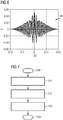
- Figures 5a-c show a second RF pulse for generating the RF pulse according to an embodiment of the invention.
- Figure 5a shows a representation of a complex amplitude A of a second RF pulse 42 over time.
- Figure 5b shows the tilt angle ⁇ of the second RF pulse 42 in the frequency domain.
- Figure 5c shows the tilt angle ⁇ of the second RF pulse 42 in the frequency domain in a logarithmic representation.
- the second RF pulse 42 preferably has a flip angle of a few hundred degrees, particularly preferably 500 to 600 degrees, and a frequency of 1 kHz to 1.5 kHz, particularly preferably 1.5 kHz.
- Figure 6 shows an RF pulse 40 according to an embodiment of the invention.
- the RF pulse 40 was generated by superimposing the first RF pulse 41, as in FIG Figures 4 ac and the second RF pulse 42 as shown in FIGS Figures 5 ac shown.
- the RF pulse is optimized for fat saturation and MT.
- MT requires a much higher tilt angle than fat saturation.
- a tilt angle of no more than 90 degrees per TR (50 ms) is sufficient, while the MT tilt angle should be as high as possible.
- the MT tilt angle 6-10 times as high as the tilt angle for fat saturation. Unwanted saturation of the water frequency increases with the tilt angle and decreases with increasing distance from the water frequency and SAR intensive pulse profile optimizations.
- the HF pulse can be optimized in such a way that it provides the tilt angle that is necessary for fat saturation and the remaining tilt angle at a larger frequency distance in addition to the Provides water frequency, for example at 1.5 kHz. This is achieved by superimposing the pulse envelopes of the first RF pulse 41 and the second RF pulse 42, for example RF pulses with 2x20: 90 degrees at the fat saturation frequency and 500 degrees at 1 kHz.
- the RF pulse 40 preferably has a uniform tilt angle of 90 degrees at approximately 400 Hz next to the water frequency 32, and a tilt angle of 500 degrees near 1 kHz next to the water frequency 32, the tilt angle being negligible at the water frequency , or less than 1 degree.
- the HF pulse 40 is on the side of the water frequency 32 on which the fat frequency 33 is located.
- Figure 7 shows a flowchart with steps for carrying out a method for displaying vessels according to an exemplary embodiment according to the invention.
- step S40 a magnetic field is applied to an imaging volume 30 and an inflow volume 31 to an examined person 12.
- step S42 the imaging volume 30 is excited by an RF pulse 40, which fulfills a magnetization transfer function, a fat saturation function, while the magnetic field is applied.
- the RF pulse 40 has a frequency distribution, the frequencies of which are essentially lower than the center frequency of the water 32 in the imaging volume 30, and which the fat frequency 33 in the imaging volume 30 include.
- the magnetic field has a magnetic field distribution which has an apex region with essentially no spatial gradient in the imaging volume 30 and has a higher spatial gradient in the inflow volume 31.
- step S43 MR signals are measured from the imaging volume 30 to display vessels. The method ends in step S44.
- a method for vascular imaging with the help of a magnetic resonance system based on the TOF technology is provided, with a fixed magnetization in particular of brain tissue, spinal fluid and fat in an imaging volume 30, which generate undesired background signals, according to the invention by means of an RF pulse 40 suppressed simultaneously applied magnetic field.
- background signals are suppressed in the method for vascular imaging without influencing the spins of the vascular fluid flowing into the imaging volume. This enables faster and more efficient MR imaging for vascular imaging, which has reduced examination costs due to the low expenditure of time and personnel.
Description
Die vorliegende Erfindung betrifft ein Verfahren zur Gefäßdarstellung mit Hilfe einer Magnet-Resonanz (MR)-Anlage basierend auf der Time-of-Flight (TOF)-Technik. Weiter werden die zugehörige MR-Anlage, ein Computerprogrammprodukt und ein elektronisch lesbarer Datenträger bereitgestellt.The present invention relates to a method for vascular imaging with the aid of a magnetic resonance (MR) system based on the time-of-flight (TOF) technique. The associated MR system, a computer program product and an electronically readable data carrier are also provided.
Eine Klasse von MR-Bildgebungverfahren, insbesondere Perfusions- und Angiographiemessungen mit der TOF-Technik, aber auch einige 2D-Herzbildgebungsverfahren, verwendet einen zuflussbasierten Kontrast. Bei letzteren verstärkt der Zufluss lediglich bereits den vorhandenen Kontrast der Gefäßwände und vereinfacht so deren Darstellung, während Perfusions- und Angiographiemessungen allein auf zuflussbasiertem Kontrast basieren. In dem Fall, dass quantitative Zuflussinformationen extrahiert werden sollen, wie etwa bei Perfusionsmessungen, wird ein Differenzbildgebungsverfahren angewandt, um das Hintergrundsignal zu eliminieren, d.h. eine Subtraktion zweier Datensätze mit unterschiedlichen Zufluss-Magnetisierungsvorbereitungen wird durchgeführt. Dieser Ansatz verdoppelt jedoch die Messzeit und erfordert zudem eine Registrierung der beiden Datensätze zueinander. Daher wird dieser Schritt in Fällen übersprungen, in denen quantitative Informationen nicht gebraucht werden, z.B. bei einer Bildgebung der vaskulären Geometrie. Stattdessen wird das Hintergrundsignal soweit möglich mit Hilfe von MR-Verfahren unterdrückt.One class of MR imaging methods, in particular perfusion and angiography measurements with the TOF technique, but also some 2D cardiac imaging methods, use an inflow-based contrast. In the case of the latter, the inflow merely increases the existing contrast of the vessel walls and thus simplifies their representation, while perfusion and angiography measurements are based solely on inflow-based contrast. In the event that quantitative inflow information is to be extracted, such as in perfusion measurements, differential imaging is used to eliminate the background signal, i.e. a subtraction of two data sets with different inflow magnetization preparations is carried out. However, this approach doubles the measurement time and also requires the two data sets to be registered with one another. Therefore this step is skipped in cases where quantitative information is not needed, e.g. when imaging the vascular geometry. Instead, the background signal is suppressed as far as possible with the aid of MR methods.
Die MR-Bildgebung basierend auf der TOF-Technik ist ein nicht invasives Bildgebungsverfahren zur Darstellung der Gefäßstruktur eines Untersuchungsobjekts, welches auf dem Hineinfließen von "frischen" nicht vorgesättigten Spins in ein Bildgebungsvolumen beruht. Die ortsfeste Magnetisierung, d.h. die ortsfesten Spins der Bildgebungsebene werden durch wiederholte Anregung in einem kurzen Zeitabstand gesättigt. Das Signal dieser Magnetisierung ist weitgehend unterdrückt, während die nicht vorgesättigte Magnetisierung, die sich beispielsweise durch den Blutfluss während der Aufnahme in die Bildgebungsebene hinein ergibt, einen hohen Signalanteil aufweist.MR imaging based on the TOF technique is a non-invasive imaging method for displaying the vascular structure of an examination subject, which is based on the flow of "fresh" unsaturated spins into an imaging volume. The stationary magnetization, ie the stationary spins of the imaging plane, are saturated by repeated excitation in a short time interval. The The signal of this magnetization is largely suppressed, while the non-presaturated magnetization, which results, for example, from the blood flow during the exposure into the imaging plane, has a high signal component.
Für die MR-Bildgebung basierend auf der TOF-Technik des Kopfgefäßsystems sind insbesondere die im folgenden beschriebenen Verfahren zum Unterdrücken der von Gehirngewebe, Spinalflüssigkeit und Fett verursachten Hintergrundsignale bekannt.For MR imaging based on the TOF technique of the head vasculature, the methods described below for suppressing the background signals caused by brain tissue, spinal fluid and fat are known in particular.
Ein erstes bekanntes Verfahren zum Unterdrücken der Hintergrundsignale ist das Anwenden hoher Kippwinkel bei der Bildaufnahme, um Gewebe mit langen T1-Zeiten, insbesondere Flüssigkeiten, zu unterdrücken. Der Kippwinkel ist durch die Tatsache eingeschränkt, dass er das Signal mit jedem Puls verringert, daher begrenzt er die Distanz, über die zufließende Spins in dem Bildgebungsvolumen beobachtet werden können, d.h. die Schichtdicke des Bildgebungsvolumens. Typischerweise ermöglichen Kippwinkel im Bereich von 15 Grad/24 ms eine gute Hintergrundsignalunterdrückung bei Schichtdicken von bis zu 2 cm.A first known method for suppressing the background signals is the use of high tilt angles during image acquisition in order to suppress tissue with long T1 times, in particular liquids. The tilt angle is limited by the fact that it decreases the signal with each pulse, therefore it limits the distance over which inflowing spins can be observed in the imaging volume, i.e. the slice thickness of the imaging volume. Typically, tilt angles in the range of 15 degrees / 24 ms allow good background signal suppression with layer thicknesses of up to 2 cm.
Ein weiteres bekanntes Verfahren zur Unterdrückung von Hintergrundsignalen ist das Opposed-Phase-Imaging-Verfahren. Dabei wird die Echozeit (TE) derart gewählt, dass Fett und Wasser nicht phasengleich (dephasiert) sind, z.B. ungefähr 7 ms bei 1,5 T und 3,4 ms bei 3 T. Dadurch werden Signale von Voxel, welche eine Wasser-Fett-Mischung enthalten, reduziert. Allerdings sind Voxel mit reinem Fett immer noch hell sichtbar und beeinträchtigen die Gefäßsichtbarkeit in diesen Bereichen oder im Allgemeinen in nichtselektiven Maximumintensitätsprojektionen (MIP). Insbesondere bei 1,5 T verlängert diese Bedingung die Echozeit, wodurch ein T2*-basierter Signalverlust und eine Verlängerung der Erfassungszeit verursacht wird. Um das Signal für derartige Echozeiten zu stabilisieren, müssen Flusskompensationsgradienten angewendet werden. Dabei wird ein Dephasieren aufgrund einer laminaren, geraden Strömung kompensiert, nicht jedoch ein Dephasieren aufgrund einer turbulenten Strömung oder einer Strömung entlang einer Krümmung. Daher wäre es vorteilhaft, die Echozeit zu minimieren, z.B. durch das Verwenden von Ultrashort-Echo-Time (UTE) -Techniken, und das Hintergrundsignal von Fett mit einem anderen Verfahren zu unterdrücken.Another known method for suppressing background signals is the opposed phase imaging method. The echo time (TE) is selected in such a way that fat and water are not in phase (dephased), for example approximately 7 ms at 1.5 T and 3.4 ms at 3 T. This results in signals from voxels indicating a water-fat -Mixture included, reduced. However, voxels with pure fat are still brightly visible and impair vascular visibility in these areas or in general in non-selective maximum intensity projections (MIP). At 1.5 T in particular, this condition increases the echo time, causing a T2 * -based signal loss and an increase in the acquisition time. In order to stabilize the signal for such echo times, flow compensation gradients must be applied. Dephasing due to a laminar, straight flow is compensated for, but not dephasing due to a turbulent flow or a flow along a curve. It would therefore be advantageous to minimize the echo time, for example by using Ultrashort-Echo-Time (UTE) techniques, and to suppress the background signal from fat with another method.
Ein weiteres bekanntes Verfahren zur Unterdrückung von Hintergrundsignalen ist die Sättigung durch eine Magnetisierungsübertragung (MT) mittels eines MT-Pulses. Dabei werden unbewegliche Protonen in Makromolekülen mit einer verbreiterten Resonanzfrequenz durch starke HF-Pulse mit Frequenzen in Bereichen, welche 500 Hz bis 2000 Hz neben der Wasserfrequenz liegen, gesättigt. Diese Protonen koppeln mit den beobachtbaren hochmobilen Wasserprotonen, wodurch eine Sättigung der unbeweglichen Protonen auch zu einer Sättigung des beobachteten Signals führt. Allerdings sind beobachtbare Fettprotonen nicht gleich stark an die unbeweglichen Protonen gekoppelt und deswegen kann das Fettsignal nicht durch dieses Verfahren unterdrückt werden. Die Sättigung kann durch Erhöhen der abgestrahlten HF-Energie, limitiert durch Specific-Absorption-Rate (SAR)-Grenzwerte, und durch Minimieren des Abstandes der Frequenz von der Resonanzfrequenz, limitiert durch die Sättigung des Bluts, verstärkt werden. Da der MT-Puls nichtselektiv ist, muss nicht nur die Sättigung des Bluts innerhalb des Bildgebungsvolumens, sondern auch die Sättigung entlang der zuführenden Gefäße, z.B. der Carotiden, berücksichtigt werden.Another known method for suppressing background signals is saturation by means of a magnetization transfer (MT) by means of an MT pulse. In this case, immobile protons in macromolecules with a broadened resonance frequency are saturated by strong RF pulses with frequencies in ranges that are 500 Hz to 2000 Hz next to the water frequency. These protons couple with the observable highly mobile water protons, whereby a saturation of the immobile protons also leads to a saturation of the observed signal. However, observable fat protons are not equally strongly coupled to the immobile protons and therefore the fat signal cannot be suppressed by this method. The saturation can be increased by increasing the radiated RF energy, limited by specific absorption rate (SAR) limits, and by minimizing the distance between the frequency and the resonance frequency, limited by the saturation of the blood. Since the MT pulse is nonselective, not only must the saturation of the blood within the imaging volume, but also the saturation along the supplying vessels, e.g. the carotids.
Aus der Druckschrift
Weiterhin ist die sogenannte frequenzselektive Fettsättigung ein bekanntes Verfahren zur Unterdrückung von Hintergrundsignalen. Dabei wird durch einen frequenzselektiven, räumlich nicht selektiven HF-Puls die Fettmagnetisierung im Bildgebungsvolumen angeregt, ohne die Wassermagnetisierung im Bildgebungsvolumen anzuregen. Die transverse Magnetisierung der angeregten Fettmagnetisierung wird zusätzlich durch Gradient Spoiling ausgelöscht und das Wassersignal kann somit separat gemessen werden. Dennoch ist dieses Verfahren unzuverlässig, da es das Blut in den zuführenden Gefäßen sättigt, und dadurch manche Blutgefäße im Bildgebungsvolumen nicht aufzulösen sind. Diese unerwünschte Sättigung des Bluts in den zuführenden Gefäßen wird durch Inhomogenitäten des B0-Magnetfelds verursacht, insbesondere im Nackenbereich und dem oberen Brustkorb einer Untersuchungsperson, wobei insbesondere die Wasserfrequenz durch die Inhomogenitäten hin zu der nominellen Fettfrequenz verschoben wird, d.h. in Richtung hin zu niedrigeren Frequenzen.Furthermore, the so-called frequency-selective fat saturation is a known method for suppressing background signals. A frequency-selective, spatially non-selective HF pulse stimulates the fat magnetization in the imaging volume without stimulating the water magnetization in the imaging volume. The transverse magnetization of the excited fat magnetization is also canceled out by gradient spoiling and the water signal can thus be measured separately. However, this method is unreliable because it saturates the blood in the supplying vessels, and as a result some blood vessels in the imaging volume cannot be resolved. This undesirable saturation of the blood in the supplying vessels is caused by inhomogeneities in the B0 magnetic field, in particular in the neck area and the upper chest of the person being examined, with the water frequency in particular being shifted by the inhomogeneities towards the nominal fat frequency, i.e. towards lower frequencies .
Wegen der beschriebenen Nachteile der herkömmlichen Verfahren zur Unterdrückung von Hintergrundsignalen muss oft zusätzlich eine manuelle Nachbearbeitung des MR-Bildes durch Ausschneiden des perkutanen Fetts vor der Erzeugung von Maximumintensitätsprojektionen (MIP) durchgeführt werden, was zu einem erhöhten Zeit- und Personalaufwand, und damit erhöhten Untersuchungskosten führt.Because of the described disadvantages of the conventional methods for suppressing background signals, manual post-processing of the MR image by cutting out the percutaneous fat before generating maximum intensity projections (MIP) often has to be carried out, which leads to increased expenditure of time and personnel and thus increased examination costs leads.
MR-Verfahren, bei denen unter anderem auch Hintergrundsignale unterdrückt werden, sind beispielsweise in der
Aus der Druckschrift
Aus der Druckschrift
Es besteht daher Bedarf nach einem verbesserten Verfahren zum Unterdrücken von Hintergrundsignalen bei der MR-Bildgebung basierend auf der TOF-Technik, welches Hintergrundsignale von Gehirngewebe, Spinalflüssigkeit und Fett mit hoher Zuverlässigkeit unterdrückt, welches einen hohen Kontrast der MR-Bilder und eine gute Erkennbarkeit von insbesondere kleinen Gefäßen bereitstellt, und welches dadurch eine effiziente und kostengünstige MR-Bildgebung ohne die Notwendigkeit von manuellem Nachbearbeiten der MR-Bilder ermöglicht.There is therefore a need for an improved method for suppressing background signals in MR imaging based on the TOF technique, which background signals from Brain tissue, spinal fluid and fat are suppressed with high reliability, which provides a high contrast of the MR images and good recognizability of especially small vessels, and which thereby enables efficient and inexpensive MR imaging without the need for manual post-processing of the MR images.
Diese Aufgabe wird mit den Merkmalen der unabhängigen Ansprüche gelöst. In den abhängigen Ansprüchen sind weitere Ausführungsformen der Erfindung beschrieben.This object is achieved with the features of the independent claims. Further embodiments of the invention are described in the dependent claims.
Gemäß einem ersten Aspekt wird ein Verfahren zur Gefäßdarstellung basierend auf der Time-of-Flight (TOF)-Technik mit Hilfe einer MR-Anlage bereitbestellt. In einem ersten Schritt wird ein Magnetfeld an ein Bildgebungsvolumen und ein Zuflussvolumen, von welchem Flüssigkeit in das Bildgebungsvolumen eintritt, einer Untersuchungsperson angelegt. In einem weiteren Schritt wird das Bildgebungsvolumen durch einen HF-Puls, welcher eine Magnetisierungs-Transferfunktion und eine Fett-Sättigungsfunktion erfüllt, angeregt während das Magnetfeld angelegt ist. Der HF-Puls, welcher eine Magnetisierungs-Transferfunktion und eine Fett-Sättigungsfunktion erfüllt, kann genau einen HF-Puls umfassen. Das Bildgebungsvolumen kann auch durch einen HF-Präparationsblock angeregt werden. Ein HF-Präparationsblock kann einen oder mehrere HF-Pulse umfassen, welche eine Fett-Sättigungsfunktion, eine Magnetisierungs-Transferfunktion und eine TSAT-Funktion erfüllen. In einem zusätzlichen Schritt werden MR-Signale aus dem Bildgebungsvolumen zum Darstellen von Gefäßen gemessen. Dabei weist der HF-Puls eine Frequenzverteilung auf, deren Frequenzen im Wesentlichen niedriger als die Mittenfrequenz des Wassers im Bildgebungsvolumen sind, d.h. auf der Seite der Fettfrequenz liegen, und welche die Fettfrequenz im Bildgebungsvolumen umfassen. Weiter weist das Magnetfeld eine Magnetfeldverteilung auf, welche durch eine Funktion angenähert ist, die derart ausgebildet ist, dass sie einen Scheitelbereich mit im Wesentlichen keinem räumlichen Gradienten im Bildgebungsvolumen aufweist und einen höheren räumlichen Gradienten im Zuflussvolumen aufweist, so dass die Wasserfrequenz im Zuflussvolumen nicht von dem HF-Puls umfasst wird. Die Funktion, welche die Magnetfeldverteilung annähert, kann nicht-linear sein. Die Funktion, welche die Magnetfeldverteilung annähert, kann anstatt des Scheitelpunktes eines symmetrischen Gradienten, d.h. beispielsweise eines z2-Shims, auch einen Sattelpunkt eines antisymmetrischen Gradienten, d.h. beispielsweise eines z3-Shims, aufweisen.According to a first aspect, a method for displaying vessels based on the time-of-flight (TOF) technique with the aid of an MR system is provided. In a first step, a magnetic field is applied to an imaging volume and an inflow volume, from which liquid enters the imaging volume, of an examination person. In a further step, the imaging volume is excited by an RF pulse, which fulfills a magnetization transfer function and a fat saturation function, while the magnetic field is applied. The HF pulse, which fulfills a magnetization transfer function and a fat saturation function, can comprise exactly one HF pulse. The imaging volume can also be excited by an RF preparation block. An RF preparation block can comprise one or more RF pulses which fulfill a fat saturation function, a magnetization transfer function and a TSAT function. In an additional step, MR signals are measured from the imaging volume for displaying vessels. The HF pulse has a frequency distribution whose frequencies are essentially lower than the center frequency of the water in the imaging volume, ie are on the side of the fat frequency, and which include the fat frequency in the imaging volume. Furthermore, the magnetic field has a magnetic field distribution which is approximated by a function which is designed such that it has an apex area with essentially no spatial gradient in the imaging volume and has a higher spatial gradient in the inflow volume, so that the water frequency in the inflow volume does not vary from the HF pulse is included. The function which approximates the magnetic field distribution can be non-linear. The function which approximates the magnetic field distribution can also have a saddle point of an antisymmetric gradient, ie for example a z3 shim, instead of the apex of a symmetrical gradient, ie for example a z2 shim.
Die Feldverteilung ist derart ausgebildet, dass die Mittenfrequenz des Wassers in dem Zuflussvolumen in Richtung höherer Frequenzen verschoben wird, wodurch sie durch den HF-Puls nicht mehr beeinflusst wird. Insbesondere kann die Feldverteilung des Magnetfeldes eine im Wesentlichen konstante Feldstärke innerhalb des Bildgebungsvolumens aufweisen. Insbesondere können die Feldschwankungen des Magnetfeldes innerhalb des Bildgebungsvolumens kleiner als der Frequenzabstand zwischen der Fettfrequenz und der Wasserfrequenz sein, wodurch eine homogene Fettsättigung ermöglicht wird. Eine Längsrichtung kann weiter derart definiert sein, dass sie in Richtung von Fuß zu Kopf einer Untersuchungsperson verläuft, wobei die Längsrichtung durch das Zentrum des Bildgebungsvolumens und das Zentrum des Zuflussvolumens verläuft, und wobei sie weiter herkömmlicherweise auch als z-Richtung bezeichnet wird. Die Feldverteilung des Magnetfeldes weist im Zuflussvolumen einen im Vergleich zum Bildgebungsvolumen höheren Feldstärkegradienten in Längsrichtung auf, d.h. die Feldstärke des Magnetfeldes steigt in z-Richtung nichtlinear an, und ist insbesondere angenähert durch eine mathematische Funktion mindestens zweiten Grades. Das Magnetfeld weist in Bezug zum B0-Feld eine Polarität auf, welche die Feldstärke des B0-Feldes ausserhalb des Bildgebungsvolumens, zumindest in der Richtung, aus der das Blut einströmt, d.h. zumindest im Zuflussvolumen, verringert. Dadurch wird die Mittenfrequenz des Wassers in Richtung weg von der Fettfrequenz verschoben, insbesondere hin zu höheren Frequenzen verschoben, und weiter insbesondere mit steigendem Abstand in Längsrichtung nichtlinear hin zu höheren Frequenzen verschoben.The field distribution is designed such that the center frequency of the water in the inflow volume is shifted in the direction of higher frequencies, so that it is no longer influenced by the RF pulse. In particular, the field distribution of the magnetic field can have an essentially constant field strength within the imaging volume. In particular, the field fluctuations of the magnetic field within the imaging volume can be smaller than the frequency spacing between the fat frequency and the water frequency, whereby a homogeneous fat saturation is made possible. A longitudinal direction can further be defined such that it runs in the direction from foot to head of a person being examined, the longitudinal direction running through the center of the imaging volume and the center of the inflow volume, and where it is also conventionally referred to as the z-direction. The field distribution of the magnetic field in the inflow volume has a higher field strength gradient in the longitudinal direction than in the imaging volume, ie the field strength of the magnetic field increases non-linearly in the z direction and is in particular approximated by a mathematical function of at least second degree. In relation to the B0 field, the magnetic field has a polarity which reduces the field strength of the B0 field outside the imaging volume, at least in the direction from which the blood flows in, ie at least in the inflow volume. As a result, the center frequency of the water is shifted in the direction away from the fat frequency, in particular shifted towards higher frequencies, and further shifted nonlinearly towards higher frequencies in particular with increasing distance in the longitudinal direction.
Durch das erfindungsgemäße Verfahren werden bei der Gefäßdarstellung mit Hilfe einer MR-Anlage basierend auf der TOF-Technik Hintergrundsignale von Gehirngewebe, Spinalflüssigkeit und Fett zuverlässiger unterdrückt und es wird ein höherer Kontrast und eine bessere Erkennbarkeit von insbesondere kleinen Gefäßen in der Nähe des Schädels und der Augenhöhle in resultierenden MR-Bildern bereitstellt als bei herkömmlichen Verfahren zum Unterdrücken von Hintergrundsignalen. Weiter kann durch das erfindungsgemäße Verfahren die Anwendung Opposed-Phase-Imaging-Verfahrens zur Unterdrückung von Hintergrundsignalen unterbleiben, wodurch vorteilhaft eine Minimierung der TE im bestehenden Messprotokoll durchgeführt werden kann, und besonders vorteilhaft eine wesentlich schnellere Ultrashort-Echo-Time (UTE) -MR-Bildgebung mit hohem Kontrast und ohne Signallücken aufgrund von turbulenten Strömungen ermöglicht wird. Zudem entfällt durch das erfindungsgemäße Verfahren die Notwendigkeit von manuellem Nachbearbeiten der MR-Bilder, um perkutanes Fett manuell zu entfernen. Insbesondere wird die Gefäßsichtbarkeit von Inline SAG und COR MIPs verbessert, was wiederum die Notwendigkeit von manuellem "Schädelfreistellen", wie es typischer weise im Klinikalltag durchgeführt wird, verringert. Dadurch wird eine schnellere und effizientere MR-Bildgebung zur Gefäßdarstellung mit Hilfe einer MR-Anlage ermöglicht, welche einen geringen Zeit- und Personalaufwand für eine Untersuchung, und damit verringerte Untersuchungskosten aufweist im Vergleich zu herkömmlichen Verfahren zur Gefäßdarstellung mit Hilfe einer MR-Anlage.With the method according to the invention, background signals from brain tissue, spinal fluid and fat are more reliably suppressed during the vascular imaging with the aid of an MR system based on the TOF technique and a higher contrast and better visibility of especially small vessels near the skull and the Eye socket in resulting MR images than with conventional methods for suppressing background signals. The method according to the invention also makes it possible to omit the use of the opposed phase imaging method for suppressing background signals, whereby the PD can advantageously be minimized in the existing measurement protocol, and particularly advantageously a significantly faster ultrashort echo time (UTE) MR Imaging with high contrast and without signal gaps due to turbulent flows is enabled. In addition, the method according to the invention eliminates the need for manual post-processing of the MR images in order to manually remove percutaneous fat. In particular, the vascular visibility of Inline SAG and COR MIPs is improved, which in turn reduces the need for manual "cranial relief", as is typically done in everyday clinical practice. This enables faster and more efficient MR imaging for vascular imaging with the aid of an MR system, which requires little time and personnel for an examination and thus has reduced examination costs compared to conventional methods for vascular imaging with the aid of an MR system.
Das Bildgebungsvolumen und das Zuflussvolumen können schichtförmig sein, wobei eine Längsachse senkrecht zu dem Bildgebungsvolumen und dem Zuflussvolumen ausgerichtet sein kann, und wobei entlang der Längsachse eine Schichtdicke des Zuflussvolumens gleich einem Vielfachen einer Schichtdicke des Bildgebungsvolumens sein kann.The imaging volume and the inflow volume can be layered, wherein a longitudinal axis can be oriented perpendicular to the imaging volume and the inflow volume, and a slice thickness of the inflow volume can be equal to a multiple of a slice thickness of the imaging volume along the longitudinal axis.
Durch die Schichtform und die im Vergleich zum Zuflussvolumen geringere Schichtdicke des Bildgebungsvolumens wird der Kontrast des MR-Bildes bei der Gefäßdarstellung weiter erhöht.Due to the slice shape and the slice thickness of the imaging volume, which is smaller in comparison to the inflow volume, the contrast of the MR image in the vascular display is further increased.
Der Scheitelbereich der Funktion kann im Wesentlichen die gleiche Dicke haben, wie die Schichtdicke des Bildgebungsvolumens, wodurch die Hintergrundsignale aufgrund von Inhomogenitäten im Zuflussvolumen zuverlässiger verringert werden.The vertex region of the function can have essentially the same thickness as the slice thickness of the imaging volume, as a result of which the background signals due to inhomogeneities in the inflow volume are reduced more reliably.
Die Schritte des Verfahrens können für mindestens ein weiteres Bildgebungsvolumen und mindestens ein weiteres Zuflussvolumen durchgeführt werden. Dabei kann das Verfahren weiter ein Anpassen der Magnetfeldverteilung an das mindestens eine weiteren Bildgebungsvolumen und das mindestens eine weitere Zuflussvolumen, derart, dass die angepasste Magnetfeldverteilung in dem mindestens einen weiteren Bildgebungsvolumen den Scheitelbereich aufweist und in dem mindestens einen weiteren Zuflussvolumen den höheren räumlichen Gradienten aufweist, umfassen.The steps of the method can be carried out for at least one further imaging volume and at least one further inflow volume. The method can further adapt the magnetic field distribution to the at least one further imaging volume and the at least one further inflow volume in such a way that the adapted magnetic field distribution in the at least one further imaging volume has the apex area and in the at least one further inflow volume has the higher spatial gradient, include.
Durch das Durchführen des Verfahrens für mehrere Bildgebungsvolumina und Zuflussvolumina werden die Zuverlässigkeit und der Kontrast der MR-Bildgebung weiter erhöht.By performing the method for a plurality of imaging volumes and inflow volumes, the reliability and the contrast of the MR imaging are further increased.
Das Anpassen der Magnetfeldverteilung kann ein lineares räumliches Verschieben der Magnetfeldverteilung umfassen, wodurch die Anpassung des Magnetfelds schnell und effizient durchgeführt werden kann.The adaptation of the magnetic field distribution can include a linear spatial displacement of the magnetic field distribution, as a result of which the adaptation of the magnetic field can be carried out quickly and efficiently.
Das Anpassen der Magnetfeldverteilung kann ein Ändern einer linearen Komponente der Magnetfeldverteilung umfassen, wodurch die Effizienz der Anpassung weiter erhöht wird.The adaptation of the magnetic field distribution can include changing a linear component of the magnetic field distribution, whereby the efficiency of the adaptation is further increased.
Die mehreren Bildgebungsvolumina können sich zumindest teilweise räumlich überschneiden. Durch die räumliche Überschneidung der mehreren Bildgebungsvolumina ist das Verfahren weniger fehleranfällig und die Unterdrückung der Hintergrundsignale zuverlässiger.The multiple imaging volumes can at least partially spatially overlap. Due to the spatial overlap of the multiple imaging volumes, the method is less error-prone and the suppression of the background signals is more reliable.
Das Verfahren kann weiter ein Erzeugen des HF-Pulses durch Überlagern eines ersten HF-Pulses und eines zweiten HF-Pulses umfassen. Das Erzeugen eines HF-Pulses durch Überlagern eines ersten HF-Pulses und eines zweiten HF-Pulses, ermöglicht eine exaktere Anpassung des HF-Pulses an mehrere Funktionen, etwa einer Magnetisierungs-Transferfunktion und eine Fett-Sättigungsfunktion, und damit einer effizientere Unterdrückung der Hintergrundsignale.The method can further include generating the RF pulse by superimposing a first RF pulse and a second RF pulse. The generation of an RF pulse by superimposing a first RF pulse and a second RF pulse, enables a more precise adaptation of the RF pulse to several functions, such as a magnetization transfer function and a fat saturation function, and thus a more efficient suppression of the background signals.
Dabei kann der erste HF-Puls einen ersten Flip-Winkel und der zweite HF-Puls einen zweiten Flip-Winkel unterschiedlich zu dem ersten Flip-Winkel aufweisen, wodurch der HF-Puls zur Anregung unterschiedlichen Gewebes angepasst werde kann, so dass er etwa eine Magnetisierungs-Transferfunktion und eine Fett-Sättigungsfunktion erfüllen kann.The first RF pulse can have a first flip angle and the second RF pulse can have a second flip angle different from the first flip angle, whereby the RF pulse can be adapted to excite different tissue, so that it has about a Can fulfill magnetization transfer function and fat saturation function.
Der erste HF-Puls kann vorzugsweise einen Flip-Winkel von 20 bis 180 Grad, besonders vorzugsweise 90 Grad, und eine Frequenz im Wesentlichen gleich der Fettfrequenz im Bildgebungsvolumen aufweisen. Diese Werte sind besonders vorteilhaft für die Fett-Sättigungsfunktion des HF-Pulses. Falls das Messen der MR-Signale im Steady State genau in der Mitte zwischen den HF-Pulsen zur Fettsättigung durchgeführt wird, ist eine Inversion, d.h. 180 Grad, für ein vollständiges Auslöschen des Fettsignals optimal. Typischerweise werden jedoch durch SAR beschränkt kleinere Kippwinkel verwendet. Bei HF-Pulsabständen << T1 von Fett, wie in dem oben beschriebenen Verfahren, kann auch ein Kippwinkel << 90 Grad gute Fettsättigung erreichen.The first RF pulse can preferably have a flip angle of 20 to 180 degrees, particularly preferably 90 degrees, and a frequency essentially equal to the fat frequency in the imaging volume. These values are particularly advantageous for the fat saturation function of the HF pulse. If the measurement of the MR signals in steady state is carried out exactly in the middle between the RF pulses for fat saturation, an inversion, i.e. 180 degrees, ideal for completely eliminating the fat signal. Typically, however, smaller tilt angles are used, restricted by SAR. With HF pulse intervals << T1 from fat, as in the method described above, a tilt angle << 90 degrees can also achieve good fat saturation.
Pro HF-Puls können mehrere Messungen von MR-Signalen aus dem Bildgebungsvolumen durchgeführt werden, wodurch die Messzeit für die Aufnahme eines MR-Bildes verringert wird.Several measurements of MR signals from the imaging volume can be carried out per RF pulse, which reduces the measurement time for recording an MR image.
Die mehreren Messungen können in gleichen zeitlichen Abständen durchgeführt werden, wodurch die Bildqualität der MR-Bilder verbessert wird.The multiple measurements can be carried out at equal time intervals, as a result of which the image quality of the MR images is improved.
Die mehreren Messungen können in Messgruppierungen mit zeitlichen Abständen zwischen den einzelnen Messungen durchgeführt werden, wobei zwischen den Messgruppierungen eine Anregung durch einen HF-Puls oder einen HF-Präparationsblock durchgeführt werden kann, und wobei der mittlere zeitliche Abstand zwischen den Messungen kleiner einem vorbestimmten Schwellenwert sein kann. Ein HF-Präparationsblock kann einen oder mehrere HF-Pulse umfassen, welche eine Fett-Sättigungsfunktion, eine Magnetisierungs-Transferfunktion und eine TSAT-Funktion erfüllen. Durch die zeitliche Gruppierung der einzelnen Messungen zu Messgruppierungen mit einem zwischen den Messgruppierungen ausgespielten HF-Puls wird die Bildqualität der MR-Bilder weiter verbessert, indem der HF-Puls ein wohldefiniertes Frequenzprofil aufweisen kann. Weiter wird die SAR Belastung für das Untersuchungsobjekt verringert.The multiple measurements can be carried out in measurement groupings with time intervals between the individual measurements, with an excitation between the measurement groupings can be carried out by an RF pulse or an RF preparation block, and wherein the mean time interval between the measurements can be less than a predetermined threshold value. An RF preparation block can comprise one or more RF pulses which fulfill a fat saturation function, a magnetization transfer function and a TSAT function. By temporally grouping the individual measurements into measurement groupings with an RF pulse played out between the measurement groupings, the image quality of the MR images is further improved in that the RF pulse can have a well-defined frequency profile. Furthermore, the SAR exposure for the examination subject is reduced.
Gemäß einem weiteren Aspekt der Erfindung wird eine MR-Anlage zur Gefäßdarstellung basierend auf der Time-of-Flight (TOF)-Technik bereitgestellt, wobei die MR-Anlage eine MR-Steuereinheit und eine Speichereinheit aufweist, wobei die Speichereinheit von der MR-Steuereinheit ausführbare Steuerinformationen speichert, und wobei die MR-Anlage ausgebildet ist, bei der Ausführung der Steuerinformationen in der MR-Steuereinheit die folgenden Schritte auszuführen. In einem Schritt wird ein Magnetfeld an ein Bildgebungsvolumen und an ein Zuflussvolumen, von dem Flüssigkeit in das Bildgebungsvolumen eintritt, einer Untersuchungsperson angelegt. In einem weiteren Schritt wird das Bildgebungsvolumen durch einen HF-Puls, welcher eine Magnetisierungs-Transferfunktion und eine Fett-Sättigungsfunktion erfüllt, angeregt während das Magnetfeld angelegt ist. In einem zusätzlichen Schritt werden MR-Signale aus dem Bildgebungsvolumen zum Darstellen von Gefäßen gemessen. Dabei weist der HF-Puls eine Frequenzverteilung auf, deren Frequenzen im Wesentlichen auf der Seite der Fettfrequenz liegen, und welche die Fettfrequenz im Bildgebungsvolumen umfassen. Weiter weist das Magnetfeld eine Magnetfeldverteilung auf, welche durch eine Funktion angenähert ist, die derart ausgebildet ist, dass sie einen Scheitelbereich mit im Wesentlichen keinem räumlichen Gradienten im Bildgebungsvolumen aufweist und einen höheren räumlichen Gradienten im Zuflussvolumen aufweist, so dass die Wasserfrequenz im Zuflussvolumen nicht von dem HF-Puls umfasst wird.According to a further aspect of the invention, an MR system for displaying vessels based on time-of-flight (TOF) technology is provided, the MR system having an MR control unit and a memory unit, the memory unit being derived from the MR control unit stores executable control information, and wherein the MR system is designed to carry out the following steps when executing the control information in the MR control unit. In one step, a magnetic field is applied to an imaging volume and to an inflow volume, from which liquid enters the imaging volume, of an examination person. In a further step, the imaging volume is excited by an RF pulse, which fulfills a magnetization transfer function and a fat saturation function, while the magnetic field is applied. In an additional step, MR signals are measured from the imaging volume for displaying vessels. The HF pulse has a frequency distribution, the frequencies of which are essentially on the side of the fat frequency, and which include the fat frequency in the imaging volume. Furthermore, the magnetic field has a magnetic field distribution which is approximated by a function which is designed such that it has an apex area with essentially no spatial gradient in the imaging volume and has a higher spatial gradient in the inflow volume, so that the water frequency in the inflow volume is not encompassed by the RF pulse.
Die MR-Anlage zur Gefäßdarstellung kann derart ausgebildet sein, dass sie der Ausführung der Steuerinformationen in der MR-Steuereinheit das Verfahren entsprechend der weiteren oben beschriebenen Merkmale auszuführen.The MR system for vascular imaging can be designed in such a way that it executes the method according to the further features described above when executing the control information in the MR control unit.
Für eine derartige MR-Anlage zur Gefäßdarstellung können technische Effekte erzielt werden, die vergleichbar sind mit den technischen Effekten, die für das Verfahren gemäß dem ersten Aspekt obenstehend beschrieben wurden.For such an MR system for vascular imaging, technical effects can be achieved which are comparable to the technical effects which were described above for the method according to the first aspect.
Gemäß einem weiteren Aspekt der Erfindung wird ein Computerprogrammprodukt bereitgestellt, welches ein Programm umfasst, das direkt in einen Speicher einer MR-Steuereinheit einer MR-Anlage ladbar ist, mit Programm-Mitteln, um die Schritte des Verfahrens entsprechend den unter dem ersten Aspekt der Erfindung beschriebenen Merkmale auszuführen, wenn das Programm in der MR-Steuereinheit der MR-Anlage ausgeführt wird.According to a further aspect of the invention, a computer program product is provided which comprises a program that can be loaded directly into a memory of an MR control unit of an MR system, with program means to carry out the steps of the method in accordance with the first aspect of the invention perform features described when the program is executed in the MR control unit of the MR system.
Gemäß einem weiteren Aspekt der Erfindung wird ein elektronisch lesbarer Datenträger mit darauf gespeicherten elektronisch lesbaren Steuerinformationen bereitgestellt, welche derart ausgestaltet sind, dass sie bei Verwendung des Datenträgers in einer MR-Steuereinheit einer MR-Anlage das Verfahren entsprechend den unter dem ersten Aspekt der Erfindung beschriebenen Merkmalen durchführen.According to a further aspect of the invention, an electronically readable data carrier is provided with electronically readable control information stored thereon, which is designed such that when the data carrier is used in an MR control unit of an MR system, the method according to the method described in the first aspect of the invention is provided Perform characteristics.
Die oben dargelegten Merkmale und Merkmale, die nachfolgend beschrieben werden, können nicht nur in den entsprechenden explizit dargelegten Kombinationen verwendet werden, sondern auch in weiteren Kombinationen oder isoliert, ohne den Schutzumfang der vorliegenden Erfindung zu verlassen.The features set out above and features which are described below can be used not only in the corresponding explicitly set out combinations, but also in further combinations or in isolation without departing from the scope of protection of the present invention.
Die Erfindung wird nachfolgend unter Bezugnahme auf die beiliegenden Zeichnungen näher erläutert.
-
Figur 1 zeigt schematisch eine MR-Anlage, mit der ein Verfahren zur Gefäßdarstellung erfindungsgemäß durchgeführt werden kann. -
Figur 2 -
Figur 3 zeigt eine schematische Darstellung der Untersuchungsperson derFigur 2 mit zugehörigen Frequenzverläufen bei angelegtem Magnetfeld der Erfindung. -
Figuren 4a-c zeigen einen ersten HF-Puls zur Erzeugung des HF-Pulses gemäß einem Ausführungsbeispiel gemäß einem Ausführungsbeispiel der Erfindung. -
Figuren 5a-c zeigen einen zweiten HF-Puls zur Erzeugung des HF-Pulses gemäß einem Ausführungsbeispiel der Erfindung. -
Figur 6 -
Figur 7 zeigt ein Flussdiagramm mit Schritten zur Durchführung eines Verfahrens zur Gefäßdarstellung gemäß einem Ausführungsbeispiel der Erfindung.
-
Figure 1 shows schematically an MR system with which a method for vascular imaging can be carried out according to the invention. -
Figure 2 shows a schematic representation of a person under examination with associated frequency curves without a magnetic field applied according to the invention. -
Figure 3 shows a schematic representation of the person being examined in FIGFigure 2 with associated frequency curves when the magnetic field of the invention is applied. -
Figures 4a-c show a first RF pulse for generating the RF pulse according to an embodiment according to an embodiment of the invention. -
Figures 5a-c show a second RF pulse for generating the RF pulse according to an embodiment of the invention. -
Figure 6 shows an RF pulse according to an embodiment of the invention. -
Figure 7 shows a flowchart with steps for performing a method for displaying vessels according to an exemplary embodiment of the invention.
Die vorliegende Erfindung betrifft ein Verfahren zur Gefäßdarstellung mit Hilfe einer MR-Anlage. Bezugnehmend auf
Eine Untersuchungsperson 12, oder allgemeiner ein Untersuchungsobjekt, ist in den Tunnel der Anlage gefahren. Die Magnetresonanzanlage weist einen Magneten 10 zur Erzeugung eines Grundfeldes B0 auf, wobei eine auf einer Liege 11 angeordnete Untersuchungsperson 12 in das Zentrum des Magneten gefahren wird, um dort ortscodierte Magnetresonanzsignale aus einem Untersuchungsabschnitt aufzunehmen. Durch Einstrahlen von Hochfrequenzpulsfolgen und Schalten von Magnetfeldgradienten kann die durch das Grundfeld B0 erzeugte Magnetisierung gestört werden durch Auslenkung der Kernspins aus der Gleichgewichtslage, und die bei der Rückkehr in die Gleichgewichtslage in Empfangsspulen induzierten Ströme können in Magnetresonanzsignale umgewandelt werden. Die allgemeine Funktionsweise zur Erstellung von MR-Bildern und die Detektion der Magnetresonanzsignale sind dem Fachmann bekannt, sodass auf eine detaillierte Erläuterung hiervon verzichtet wird.An
Die Magnetresonanzanlage weist weiterhin eine MR-Steuereinheit 13 auf, die zur Steuerung des MR-Geräts verwendet wird. Die zentrale MR-Steuereinheit 13, welche derart ausgebildet ist, dass die das unten beschriebene Verfahren für eine automatische Justierung durchführt, weist eine Gradientensteuerung 14 zur Steuerung und Schaltung der Magnetfeldgradienten auf und eine HF-Steuerung 15 zur Steuerung und Einstrahlung der HF-Pulse zur Auslenkung der Kernspins aus der Gleichgewichtlage. In einer Speichereinheit 16 können beispielsweise die für die Aufnahme der MR-Bilder notwendigen Bildgebungssequenzen abgespeichert werden, sowie alle Programme, die zum Betrieb der MR-Anlage notwendig sind. Eine Aufnahmeeinheit 17 steuert die Bildaufnahme und steuert damit in Abhängigkeit von den gewählten Bildgebungssequenzen die Abfolge der Magnetfeldgradienten und HF-Pulse und die Empfangsintervalle von MR-Signalen. Somit steuert die Aufnahmeeinheit 17 auch die Gradientensteuerung 14 und die HF-Steuerung 15. In einer Recheneinheit 20 können MR-Bilder berechnet werden, die auf eine Anzeige 18 angezeigt werden können, wobei eine Bedienperson über eine Eingabeeinheit 19 die MR-Anlage bedienen kann. Die Speichereinheit 16 kann Bildgebungssequenzen und Programmmodule aufweisen, die bei Ausführung in der Recheneinheit 20 von einem der gezeigten Module, das erfindungsgemäße Verfahren durchführen. Die HF-Steuerung 15 kann weiterhin ausgebildet sein, eine Unterdrückung von Hintergrundsignalen bei einer Gefäßdarstellung basierend auf der Time-of-Flight (TOF)-Technik zu verbessern, wie nachfolgend im Detail erläutert wird. Insbesondere speichert die Speichereinheit 16 dazu von der MR-Steuereinheit 13 ausführbare Steuerinformationen. Weiter ist die Aufnahmeeinheit 17 derart ausgebildet, dass sie das nachfolgend beschriebene Verfahren zur Gefäßdarstellung durchführen kann.The magnetic resonance system also has an
Erfindungsgemäß ist die MR-Anlage der
Eine Untersuchungsperson 12 weist ein Bildgebungsvolumen 30 und ein Zuflussvolumen 31 auf. Ein Blutgefäß 36 ist in dem Bildgebungsvolumen 30 und dem Zuflussvolumen 31 enthalten, sodass aus dem Zuflussvolumen 31 Blut in das Bildgebungsvolumen hineinfließt.An
Das Bildgebungsvolumen 30 und das Zuflussvolumen 31 sind in diesem Ausführungsbeispiel schichtförmig ausgebildet. Zudem ist eine Längsachse senkrecht zu dem Bildgebungsvolumen 30 und dem Zuflussvolumen 31 ausgerichtet, und wobei entlang der Längsachse eine Schichtdicke des Zuflussvolumens (31) gleich einem Vielfachen einer Schichtdicke des Bildgebungsvolumens (30) ist. Das Blutgefäß 36 verläuft ebenfalls im Wesentlichen entlang der Längsachse.The
Die Untersuchungsperson 12 weist unter dem Einfluss des B0-Feldes eine Wasserfrequenz 32 auf, welche der Flüssigkeit in dem Gefäß, insbesondere dem Blut in dem Blutgefäß, entspricht. Die Wasserfrequenz 32 weist einen räumlichen Verlauf in z-Richtung, oder Kopf-Fuß-Richtung der Untersuchungsperson 12, auf. Im Bereich des Bildgebungsvolumens 30 verläuft die Wasserfrequenz 32 konstant, wogegen die Wasserfrequenz aufgrund von Inhomogenitäten des Gradientenfeldes innerhalb des Zuflussvolumens 31 in einem Teilbereich des Zuflussvolumens 31 verschoben ist. In diesem Teilbereich verläuft die Wasserfrequenz 32 in dem Fett-Sättigungs-Band 34. Weiter weist die Untersuchungsperson 12 unter dem Einfluss des B0 Feldes eine Fettfrequenz 33 auf, welche Fettansammlungen, Fettanlagerungen oder anderem fetthaltigem Gewebe der Untersuchungsperson 12 im Bildgebungsvolumen 30 entspricht. Im Bereich des Bildgebungsvolumens 30 verläuft die Fettfrequenz 33 innerhalb eines Fett-Sättigungs-Bandes 34. Innerhalb des Zuflussvolumens 31 weist die Fettfrequenz 33 eine entsprechende Frequenzverschiebung auf wie die Wasserfrequenz 32. Ein Magnetisierungs-Transfer-Band 35 verläuft neben der Wasserfrequenz 32 auf der Seite, welche der Fettfrequenz abgewandt ist, oder in anderen Worten neben der Wasserfrequenz 32 in Richtung höherer Frequenzen, ohne Überschneidungen mit der Wasserfrequenz 32. In den Randbereichen der Untersuchungsperson fällt das B0-Feld ab, sodass auch die Wasserfrequenz 32 und die Fettfrequenz 32 abfallen. Dies bedeutet, dass bei Verwendung eines Sättigungs-Pulses mit dem Band 34 Teile des einfließenden Blutes mit gesättigt werden würden, was unerwünscht ist.Under the influence of the B0 field, the person being examined 12 has a
Während das Magnetfeld angelegt ist, sind die Resonanzfrequenzen im Einflussbereich des Magnetfelds, und insbesondere die Resonanzfrequenzen im Zuflussvolumen 31, verschoben. Erfindungsgemäß ist das Magnetfeld derart ausgebildet, dass die Verschiebung der Resonanzfrequenzen im Zuflussvolumen 31 mit einem im Vergleich zum Bildgebungsvolumen 30 höheren Gradienten, insbesondere nichtlinear mit einem Abstand in z-Richtung zu dem Bildgebungsvolumen 30, ansteigt.While the magnetic field is applied, the resonance frequencies in the area of influence of the magnetic field, and in particular the resonance frequencies in the
Insbesondere ist die Wasserfrequenz 32 im Zuflussvolumen 31 derart in Richtung von der dem Fett-Sättigungs-Band 34 weg verschoben, dass ein nichtselektiv eingestrahlter Fett-Sättigungs-Puls, welcher eine Frequenzverteilung aufweist, die dem Fett-Sättigungs-Band 34 im Bereich des Bildgebungsvolumens 30 entspricht, die Wasserfrequenz 32 im Bereich des Zuflussvolumens 31 nicht umfasst. Dadurch wird Blut, welches sich im Blutgefäß 36 im Zuflussvolumen 31 befindet und welches in das Bildgebungsvolumen 30 fließt, nicht angeregt.In particular, the
In einem Ausführungsbeispiel, in welchem das Blutgefäß 36 in der Nähe des Isozentrums des Bildgebungsvolumens 30 gelegen ist, kann das Anlegen des Magnetfeldes durch eine Anpassung des z2-Shims erfolgen, wobei in Folge auch die übrigen Shims zweiter Ordnung angepasst werden müssen.In an embodiment in which the
In einem anderen Ausführungsbeispiel kann ein einfacher Shim-Algorithmus aus folgenden Schritten bestehen: Optimieren der B0-Homogenität in dem Bildgebungsvolumen 30 mit der Randbedingung, den z2-Shim bei einem fixen Wert zu halten, z.B. bei dem Tune-Up-Wert plus 1500 µT/M^2.
In einem Ausführungsbeispiel werden die Schritte des Verfahrens für mindestens ein weiteres Bildgebungsvolumen und mindestens ein weiteres Zuflussvolumen durchgeführt. Bedingung für eine Fett-Sättigung über das gesamte Bildgebungsvolumen limitiert den Wert des z2-Offsets. Dieses Limit skaliert mit einem Erstrecken des Bildgebungsvolumens 30 in z-Richtung. Die TOF-Technik wird immer unter Verwenden der Multiple-Overlapping-Transverse-Slab-Acquisition (MOTSA)-Technik durchgeführt. Zum Beispiel wird ein transverses Untersuchungsvolumen mit 10 cm Schichtdicke durch 6 überlappende Bildgebungsvolumina 30 mit 2 cm Schichtdicke abgedeckt. Dabei werden die Bildgebungsvolumina 30 sequentiell gemessen, daher kann das Magnetfeld für jedes Bildgebungsvolumen 30 einzeln optimiert und angepasst werden. In einem Ausführungsbeispiel wird die quadratische Feldverteilung entlang der z-Achse verschoben. Bei schrägen Bildgebungsvolumina (typischerweise T>C) muss der z2-Wert reduziert werden, damit er mit der Dicke des Bildgebungsvolumens übereinstimmt, wenn diese auf die z-Achse projiziert wird. In einem anderen Ausführungsbeispiel muss die Parabelrichtung unter Verwenden der anderen Shim-Kanäle zweiter Ordnung geneigt werden.In another exemplary embodiment, a simple shim algorithm can consist of the following steps: Optimizing the B0 homogeneity in the
In one exemplary embodiment, the steps of the method are carried out for at least one further imaging volume and at least one further inflow volume. The condition for fat saturation over the entire imaging volume limits the value of the z2 offset. This limit scales with an extension of the
Somit wird die Magnetfeldverteilung an das mindestens eine weiteren Bildgebungsvolumen und das mindestens eine weitere Zuflussvolumen derart angepasst, dass die angepasste Magnetfeldverteilung in dem mindestens einen weiteren Bildgebungsvolumen den Scheitelbereich aufweist und in dem mindestens einen weiteren Zuflussvolumen den höheren räumlichen Gradienten aufweist.The magnetic field distribution to the at least one further imaging volume and the at least one further imaging volume is thus applied Inflow volume adapted in such a way that the adapted magnetic field distribution has the apex region in the at least one further imaging volume and has the higher spatial gradient in the at least one further inflow volume.
In einem Ausführungsbeispiel werden mehrere Messungen pro HF-Puls 40 durchgeführt. Die HF-Pulse 40 sollten die Bildaufnahmedauer nicht verlängern. Daher werden pro HF-Puls mehrere Auslesungen durchgeführt, wobei der durchschnittliche zeitliche Abstand zwischen den Auslesungen konstant gehalten wird, um den TOF-Kontrast beizubehalten, z.B. können statt einer Auslesung pro Repetitionszeit TR = 24 ms auch zwei Auslesungen in 48 ms oder drei Auslesungen in 72 ms durchgeführt werden. Die Bildqualität ist unabhängig von der Positionierung der Auslesungen in der TR, sie können äquidistant oder ohne Pause ausgespielt werden, wodurch eine größere Pause pro TR gelassen wird, welche groß genug ist, um einen langen MT- und Fett-Sättigungs-Puls auszuspielen, welcher ein wohldefiniertes Frequenzprofil und ein niedriges SAR aufweist.In one embodiment, several measurements are performed per
In einem Ausführungsbeispiel werden TSAT-Pulse und MT-Pulse abwechselnd ausgespielt. In einem weiteren Ausführungsbeispiel werden TSAT-Pulse und MT-Pulse abwechselnd mit variierender Repetitionszeit TR ausgespielt. In einem weiteren Ausführungsbeispiel werden mindestens ein TSAT-Puls und mindestens ein MT-Puls in einer Repetitionszeit TR ausgespielt.In one embodiment, TSAT pulses and MT pulses are played out alternately. In a further exemplary embodiment, TSAT pulses and MT pulses are played out alternately with a varying repetition time TR. In a further exemplary embodiment, at least one TSAT pulse and at least one MT pulse are played out in a repetition time TR.
Der erste HF-Puls 41 weist vorzugsweise einen Flip-Winkel von 20 bis 90 Grad, besonders vorzugsweise 90 Grad, und eine Frequenz im Wesentlichen gleich der Fettfrequenz 33 im Bildgebungsvolumen 30 auf.The
Der zweite HF-Puls 42 weist vorzugsweise einen Flip-Winkel von einigen hundert Grad, besonders vorzugsweise 500 bis 600 Grad, und eine Frequenz von 1 kHz bis 1,5 kHz, besonders vorzugsweise 1,5 kHz, auf.The
Der HF-Puls 40 wurde erzeugt durch Überlagerung des ersten HF-Pulses 41, wie in den
In einem Ausführungsbeispiel wird der HF-Puls für Fett-Sättigung und MT optimiert. MT benötigt einen viel höheren Kippwinkel als eine Fett-Sättigung. Für eine effektive Fett-Sättigung genügt bereits ein Kippwinkel von nicht mehr als 90 Grad pro TR (50 ms), während der MT-Kippwinkel so hoch wie möglich sein sollte. In einigen Ausführungsbeispielen ist der MT-Kippwinkel 6-10 mal so hoch wie der Kippwinkel für die Fett-Sättigung. Unerwünschte Sättigung der Wasserfrequenz erhöht sich mit dem Kippwinkel und verringert sich mit zunehmendem Abstand von der Wasserfrequenz und SAR intensiven Pulse-Profil-Optimierungen. Da der MT-Effekt nur in geringem Maße vom Abstand von der Wasserfrequenz abhängt, kann der HF-Puls derart optimiert werden, dass er den Kippwinkel, welcher für die Fett-Sättigung notwendig ist, bereitstellt und den übrigen Kippwinkel bei einem größeren Frequenzabstand neben der Wasserfrequenz bereitstellt, z.B. bei 1,5 kHz. Dies wird durch das Überlagern der Pulshüllen des ersten HF-Pulses 41 und des zweiten HF-Pulses 42 erreicht, z.B. HF-Pulse mit 2ex20: 90 Grad bei der Fett-Sättigungs-Frequenz und 500 Grad bei 1 kHz.In one embodiment, the RF pulse is optimized for fat saturation and MT. MT requires a much higher tilt angle than fat saturation. For effective fat saturation, a tilt angle of no more than 90 degrees per TR (50 ms) is sufficient, while the MT tilt angle should be as high as possible. In some embodiments, the MT tilt angle 6-10 times as high as the tilt angle for fat saturation. Unwanted saturation of the water frequency increases with the tilt angle and decreases with increasing distance from the water frequency and SAR intensive pulse profile optimizations. Since the MT effect depends only to a small extent on the distance from the water frequency, the HF pulse can be optimized in such a way that it provides the tilt angle that is necessary for fat saturation and the remaining tilt angle at a larger frequency distance in addition to the Provides water frequency, for example at 1.5 kHz. This is achieved by superimposing the pulse envelopes of the
In einem Ausführungsbeispiel weist der HF-Puls 40 vorzugsweise einen uniformen Kippwinkel von 90 Grad bei ungefähr 400 Hz neben der Wasserfrequenz 32, und einen Kippwinkel von 500 Grad in der Nähe von 1 kHz neben der Wasserfrequenz 32 auf, wobei der Kippwinkel bei der Wasserfrequenz vernachlässigbar, oder kleiner 1 Grad, ist. Der HF-Puls 40 befindet sich auf der Seite der Wasserfrequenz 32, auf der die Fettfrequenz 33 liegt.In one embodiment, the
Das Verfahren beginnt in Schritt S40. In Schritt S41 wird ein Magnetfeld an ein Bildgebungsvolumen 30 und ein Zuflussvolumen 31 eine Untersuchungsperson 12 angelegt. In Schritt S42 wird das Bildgebungsvolumen 30 durch einen HF-Puls 40, welcher eine Magnetisierungs-Transferfunktion eine Fett-Sättigungsfunktion erfüllt, angeregt während das Magnetfeld angelegt angelegt ist. Dabei weist der HF-Puls 40 eine Frequenzverteilung auf, deren Frequenzen im Wesentlichen niedriger als die Mittenfrequenz des Wassers 32 im Bildgebungsvolumen 30 sind, und welche die Fettfrequenz 33 im Bildgebungsvolumen 30 umfassen. Das Magnetfeld weist eine Magnetfeldverteilung auf, welche einen Scheitelbereich mit im Wesentlichen keinem räumlichen Gradienten im Bildgebungsvolumen 30 aufweist und einen höheren räumlichen Gradienten im Zuflussvolumen 31 aufweist. In Schritt S43 werden MR-Signale aus dem Bildgebungsvolumen 30 zum Darstellen von Gefäßen gemessen. Das Verfahren endet in Schritt S44.The method begins in step S40. In step S41, a magnetic field is applied to an
Zusammenfassend wird ein Verfahren zur Gefäßdarstellung mit Hilfe einer Magnetresonanz-Anlage basierend auf der TOF-Technik bereitbestellt, wobei eine ortsfeste Magnetisierung insbesondere von von Gehirngewebe, Spinalflüssigkeit und Fett in einem Bildgebungsvolumen 30, welche unerwünschte Hintergrundsignale erzeugen, erfindungsgemäß durch einen HF-Puls 40 bei gleichzeitig angelegtem Magnetfeld unterdrückt. Erfindungsgemäß werden bei dem Verfahren zur Gefäßdarstellung Hintergrundsignale unterdrückt, ohne die in das Bildgebungsvolumen zufließenden Spins der Gefäßflüssigkeit zu beeinflussen. Dadurch wird eine schnellere und effizientere MR-Bildgebung zur Gefäßdarstellung ermöglicht, welche durch einen geringen Zeit- und Personalaufwand verringerte Untersuchungskosten aufweist.In summary, a method for vascular imaging with the help of a magnetic resonance system based on the TOF technology is provided, with a fixed magnetization in particular of brain tissue, spinal fluid and fat in an
Claims (18)
- Method of vascular imaging based on the Time-of-Flight (TOF) technique with the aid of an MR system, comprising the following steps:- applying a magnetic field to an imaging volume (30) and to an inflow volume (31), from which liquid enters into the imaging volume (30), of an examination person (12, S41) ;- exciting the imaging volume (30) by way of an RF pulse (40), which fulfils a magnetisation transfer function and a fat saturation function, while the magnetic field is being applied (S42); and- measuring MR signals from the imaging volume (30) in order to visualise vessels (S43);characterised in that the RF pulse (40) has a frequency distribution whose frequencies are essentially located on the side of the fat frequency, and which comprise the fat frequency (33) in the imaging volume (30); and
the magnetic field has a magnetic field distribution, which is approximated by a function that is configured in such a way that it has an apex with essentially no spatial gradient in the imaging volume (30) and has a higher spatial gradient in the inflow volume (31), so that the water frequency in the inflow volume (31) is not comprised by the RF pulse. - Method according to claim 1, wherein the function is a mathematical function of at least the second order.
- Method according to claim 1 or 2, wherein the imaging volume (30) and the inflow volume (31) are slice-like, wherein a longitudinal axis is oriented perpendicularly to the imaging volume (30) and the inflow volume (31), and wherein along the longitudinal axis, a slice thickness of the inflow volume (31) is equal to a multiple of a slice thickness of the imaging volume (30).
- Method according to one of claims 1 to 3, wherein the apex of the function has essentially the same thickness as the slice thickness of the imaging volume (30).
- Method according to one of the preceding claims, wherein the steps of the method are carried out for at least one further imaging volume and at least one further inflow volume, also comprising:- adjusting the magnetic field distribution to the at least one further imaging volume and the at least one further inflow volume, in such a way that the adjusted magnetic field distribution has the apex in the at least one further imaging volume and the higher spatial gradient in the at least one further inflow volume.
- Method according to claim 5, wherein the adjustment of the magnetic field distribution comprises a linear spatial shift of the magnetic field distribution.
- Method according to claim 5 or 6, wherein the adjustment of the magnetic field distribution comprises a change in a linear component of the magnetic field distribution.
- Method according to one of claims 5 to 7, wherein the imaging volumes at least partially spatially overlap.
- Method according to one of the preceding claims, also comprising:- generating the RF pulse (40) by overlaying a first RF pulse (41), which fulfils a fat saturation function, and a second RF pulse (42), which fulfils a magnetisation transfer function.
- Method according to claim 9, wherein the first RF pulse (41) has a first flip angle and the second RF pulse (42) has a second flip angle different from the first flip angle.
- Method according to claim 9 or 10, wherein the first RF pulse (41) preferably has a flip angle of 20 to 90 degrees, particularly preferably 90 degrees, and a frequency essentially equal to the fat frequency (33) in the imaging volume (30).
- Method according to one of the preceding claims, wherein a plurality of measurements of MR signals from the imaging volume (30) are carried out per RF pulse (40).
- Method according to claim 12, wherein the measurements are carried out at regular time intervals.
- Method according to claim 12, wherein the measurements are carried out in measurement groups with time intervals between the individual measurements, wherein an excitation is carried out by an RF pulse (40) between the measurement groups, and wherein the mean time interval between the measurements is shorter than a predetermined threshold value.
- MR system for vascular imaging based on the Time-of-Flight (TOF) technique, wherein the MR system has an MR control unit (13) and a storage unit (16), wherein the storage unit (16) stores control information that can be executed by the MR control unit (13), and wherein the MR system is designed to carry out the following steps when the control information is executed in the MR control unit (13):- applying a magnetic field to an imaging volume (30) and to an inflow volume (31), from which liquid enters into the imaging volume (30), of an examination person (12);- exciting the imaging volume (30) by way of an RF pulse (40), which fulfils a magnetisation transfer function and a fat saturation function, while the magnetic field is being applied; and- measuring MR signals from the imaging volume (30) in order to visualise vessels;characterised in that the RF pulse (40) has a frequency distribution whose frequencies are essentially located on the side of the fat frequency, and which comprises the fat frequency (33) in the imaging volume (30); and
a field distribution of the magnetic field is approximated by a function which is configured in such a way that it has an apex with essentially no spatial gradient in the imaging volume (30) and has a higher spatial gradient in the inflow volume (31), so that the water frequency in the inflow volume (31) is not comprised by the RF pulse. - MR system for vascular imaging, wherein the MR system has an MR control unit (13) and a storage unit (16), wherein the storage unit (16) stores control information that can be executed by the MR control unit (13), and wherein the MR system is designed to carry out the method of one of claims 2 to 14 when the control information is executed in the MR control unit (13).
- Computer program product, which comprises a program, which can be loaded directly into a storage device of an MR control unit (13) of an MR system, having program means in order to carry out the steps of the method according to one of claims 1 to 14 when the program is executed in the MR control unit (13) of the MR system.
- Electronically readable data carrier with electronically readable control information stored thereon, which is configured in such a way that it carries out the method according to one of claims 1 to 14 when the data carrier is used in an MR control unit (13) of an MR system.
Priority Applications (4)
| Application Number | Priority Date | Filing Date | Title |
|---|---|---|---|
| EP17172146.7A EP3330728B1 (en) | 2017-05-22 | 2017-05-22 | Method for vascular imaging with the aid of an mr equipment |
| KR1020180056526A KR20180127917A (en) | 2017-05-22 | 2018-05-17 | Method of vascular imaging with the aid of an mr system |
| US15/984,894 US10677872B2 (en) | 2017-05-22 | 2018-05-21 | Magnetic resonance apparatus and method for vascular imaging |
| CN201810487605.6A CN108931749B (en) | 2017-05-22 | 2018-05-21 | Method for displaying blood vessels by means of an MR device |
Applications Claiming Priority (1)
| Application Number | Priority Date | Filing Date | Title |
|---|---|---|---|
| EP17172146.7A EP3330728B1 (en) | 2017-05-22 | 2017-05-22 | Method for vascular imaging with the aid of an mr equipment |
Publications (2)
| Publication Number | Publication Date |
|---|---|
| EP3330728A1 EP3330728A1 (en) | 2018-06-06 |
| EP3330728B1 true EP3330728B1 (en) | 2020-10-21 |
Family
ID=58873620
Family Applications (1)
| Application Number | Title | Priority Date | Filing Date |
|---|---|---|---|
| EP17172146.7A Active EP3330728B1 (en) | 2017-05-22 | 2017-05-22 | Method for vascular imaging with the aid of an mr equipment |
Country Status (4)
| Country | Link |
|---|---|
| US (1) | US10677872B2 (en) |
| EP (1) | EP3330728B1 (en) |
| KR (1) | KR20180127917A (en) |
| CN (1) | CN108931749B (en) |
Families Citing this family (1)
| Publication number | Priority date | Publication date | Assignee | Title |
|---|---|---|---|---|
| EP3330728B1 (en) | 2017-05-22 | 2020-10-21 | Siemens Healthcare GmbH | Method for vascular imaging with the aid of an mr equipment |
Family Cites Families (17)
| Publication number | Priority date | Publication date | Assignee | Title |
|---|---|---|---|---|
| JP3386509B2 (en) * | 1993-04-27 | 2003-03-17 | 株式会社東芝 | MR imaging method and magnetic resonance imaging apparatus |
| JP3396507B2 (en) | 1993-05-12 | 2003-04-14 | 株式会社東芝 | MR imaging method and magnetic resonance imaging apparatus |
| US7254437B2 (en) * | 1998-04-17 | 2007-08-07 | Kabushiki Kaisha Toshiba | MR imaging providing tissue/blood contrast image |
| JP2005152114A (en) | 2003-11-21 | 2005-06-16 | Ge Medical Systems Global Technology Co Llc | Mri method and mri apparatus |
| JP2005152534A (en) * | 2003-11-28 | 2005-06-16 | Ge Medical Systems Global Technology Co Llc | Magnetic resonance imaging apparatus and rf wave generation method |
| US20090185981A1 (en) * | 2006-03-24 | 2009-07-23 | Gregory Karczmar | Methods and apparatus for dynamically allocating bandwidth to spectral, temporal, and spatial dimensions during a magnetic resonance imaging procedure |
| JP5675037B2 (en) | 2007-06-29 | 2015-02-25 | 株式会社東芝 | Magnetic resonance imaging apparatus and magnetic resonance imaging method |
| JP5449805B2 (en) | 2008-04-25 | 2014-03-19 | 株式会社東芝 | Magnetic resonance imaging system |
| DE102010003895B4 (en) | 2010-04-13 | 2019-07-04 | Siemens Healthcare Gmbh | Method for generating angiographic magnetic resonance images |
| US9194923B2 (en) * | 2010-06-09 | 2015-11-24 | Hitachi Medical Corporation | Magnetic resonance imaging device and transmitting sensitivity distribution calculation method |
| US20140070805A1 (en) | 2011-04-11 | 2014-03-13 | Koninklijke Philips N.V. | Mr imaging with b1 mapping |
| WO2013027539A1 (en) * | 2011-08-24 | 2013-02-28 | 株式会社日立メディコ | Magnetic resonance imaging device, phase value correction method and program |
| KR101560463B1 (en) * | 2013-12-30 | 2015-10-16 | 가천대학교 산학협력단 | Magnetic resonance imaging method cancelling artifacts and undesired signals |
| US10092199B2 (en) | 2014-04-01 | 2018-10-09 | Siemens Healthcare Gmbh | MR imaging apparatus and method for generating a perfusion image with motion correction |
| US10052033B2 (en) | 2015-03-12 | 2018-08-21 | Siemens Healthcare Gmbh | System and method for motion-robust 3D magnetic resonance imaging of vessel walls |
| DE102015205694B3 (en) | 2015-03-30 | 2016-10-06 | Siemens Healthcare Gmbh | MR saturation taking into account the anatomical structures to be imaged |
| EP3330728B1 (en) | 2017-05-22 | 2020-10-21 | Siemens Healthcare GmbH | Method for vascular imaging with the aid of an mr equipment |
-
2017
- 2017-05-22 EP EP17172146.7A patent/EP3330728B1/en active Active
-
2018
- 2018-05-17 KR KR1020180056526A patent/KR20180127917A/en not_active Application Discontinuation
- 2018-05-21 US US15/984,894 patent/US10677872B2/en active Active
- 2018-05-21 CN CN201810487605.6A patent/CN108931749B/en active Active
Non-Patent Citations (1)
| Title |
|---|
| None * |
Also Published As
| Publication number | Publication date |
|---|---|
| EP3330728A1 (en) | 2018-06-06 |
| KR20180127917A (en) | 2018-11-30 |
| US10677872B2 (en) | 2020-06-09 |
| CN108931749B (en) | 2021-08-13 |
| CN108931749A (en) | 2018-12-04 |
| US20180335497A1 (en) | 2018-11-22 |
Similar Documents
| Publication | Publication Date | Title |
|---|---|---|
| DE102008032155B4 (en) | Method for generating an excitation in an examination subject and a magnetic resonance system | |
| DE102008014060B4 (en) | Method for determining a phase position of a magnetization and magnetic resonance system | |
| DE102005049229B3 (en) | Flip angle distribution determination method for use in magnetic resonance system for medical diagnosis, involves measuring absolute flip angle distribution using one transmission configuration as reference configuration | |
| DE102013214867B4 (en) | Determining a magnetic resonance drive sequence with concentric, circular transmission trajectories | |
| DE10230877A1 (en) | Magnetic resonance imaging device with a device for the graphic planning of contrast medium-based angiographic measurements | |
| DE102014203890B4 (en) | Silent echoplanar imaging with segmented k-space | |
| DE102009016341B4 (en) | Method for determining k-space positions for modeling RF pulses for magnetic resonance excitations and magnetic resonance apparatus and computer program for carrying out the method | |
| DE102015221888B4 (en) | Simultaneous MRI multilayer measurement | |
| DE102010035539A1 (en) | Method for compensation of eddy current fields in MRI, involves compensating zero and first orders of circuital vector field generated by magnetic resonance device by using control parameters | |
| DE102015202646B3 (en) | MR imaging with multi-slice acquisition | |
| DE10338074B4 (en) | Method for compensation of contrast inhomogeneities in magnetic resonance images and magnetic resonance measuring system and computer program product | |
| DE102013219754B4 (en) | Optimization of the noise development of a 3D gradient echo sequence in a magnetic resonance system | |
| DE102004046490B4 (en) | Method and apparatus for gradient echo imaging with continuous optimization of tissue suppression | |
| DE102007011807B3 (en) | Sequence for the magnetic resonance imaging and magnetic resonance device for this purpose | |
| DE102014206398B4 (en) | Magnetic resonance imaging method for at least two separate radio-frequency transmitting coils with time-delayed slice-selective excitation pulses | |
| DE102009053293B4 (en) | Illustration of a particle in which magnetically active substances are integrated, with an imaging magnetic resonance measurement | |
| DE102016200975A1 (en) | Diffusion-weighted magnetic resonance imaging | |
| DE102010027312B4 (en) | Method for creating MR images and correspondingly designed magnetic resonance system | |
| EP3330728B1 (en) | Method for vascular imaging with the aid of an mr equipment | |
| DE102019215046B4 (en) | Method for compensating for eddy currents when recording measurement data using magnetic resonance | |
| EP2947473B1 (en) | Creation of an mr image with the aid of a combination of a whole body coil and a local transmission coil | |
| DE102010041659B4 (en) | Generation of an optimized MR image of an examination object by irradiation of a pulse sequence comprising at least two RF pulses | |
| DE102013227170B3 (en) | Method and control device for controlling a magnetic resonance system | |
| DE102009012851B4 (en) | Method, magnetic resonance apparatus, computer program product and electronically readable data carrier for obtaining a first image data record and a second image data record of an examination subject | |
| EP0965854A2 (en) | Correction of phase errors due to concomitant gradients in MRI |
Legal Events
| Date | Code | Title | Description |
|---|---|---|---|
| PUAI | Public reference made under article 153(3) epc to a published international application that has entered the european phase |
Free format text: ORIGINAL CODE: 0009012 |
|
| STAA | Information on the status of an ep patent application or granted ep patent |
Free format text: STATUS: REQUEST FOR EXAMINATION WAS MADE |
|
| 17P | Request for examination filed |
Effective date: 20180419 |
|
| AK | Designated contracting states |
Kind code of ref document: A1 Designated state(s): AL AT BE BG CH CY CZ DE DK EE ES FI FR GB GR HR HU IE IS IT LI LT LU LV MC MK MT NL NO PL PT RO RS SE SI SK SM TR |
|
| AX | Request for extension of the european patent |
Extension state: BA ME |
|
| GRAJ | Information related to disapproval of communication of intention to grant by the applicant or resumption of examination proceedings by the epo deleted |
Free format text: ORIGINAL CODE: EPIDOSDIGR1 |
|
| GRAP | Despatch of communication of intention to grant a patent |
Free format text: ORIGINAL CODE: EPIDOSNIGR1 |
|
| GRAP | Despatch of communication of intention to grant a patent |
Free format text: ORIGINAL CODE: EPIDOSNIGR1 |
|
| STAA | Information on the status of an ep patent application or granted ep patent |
Free format text: STATUS: GRANT OF PATENT IS INTENDED |
|
| INTG | Intention to grant announced |
Effective date: 20200616 |
|
| GRAS | Grant fee paid |
Free format text: ORIGINAL CODE: EPIDOSNIGR3 |
|
| GRAA | (expected) grant |
Free format text: ORIGINAL CODE: 0009210 |
|
| STAA | Information on the status of an ep patent application or granted ep patent |
Free format text: STATUS: THE PATENT HAS BEEN GRANTED |
|
| AK | Designated contracting states |
Kind code of ref document: B1 Designated state(s): AL AT BE BG CH CY CZ DE DK EE ES FI FR GB GR HR HU IE IS IT LI LT LU LV MC MK MT NL NO PL PT RO RS SE SI SK SM TR |
|
| REG | Reference to a national code |
Ref country code: GB Ref legal event code: FG4D Free format text: NOT ENGLISH |
|
| REG | Reference to a national code |
Ref country code: CH Ref legal event code: EP |
|
| REG | Reference to a national code |
Ref country code: DE Ref legal event code: R096 Ref document number: 502017007809 Country of ref document: DE |
|
| REG | Reference to a national code |
Ref country code: IE Ref legal event code: FG4D Free format text: LANGUAGE OF EP DOCUMENT: GERMAN |
|
| REG | Reference to a national code |
Ref country code: AT Ref legal event code: REF Ref document number: 1326347 Country of ref document: AT Kind code of ref document: T Effective date: 20201115 |
|
| REG | Reference to a national code |
Ref country code: NL Ref legal event code: MP Effective date: 20201021 |
|
| PG25 | Lapsed in a contracting state [announced via postgrant information from national office to epo] |
Ref country code: NO Free format text: LAPSE BECAUSE OF FAILURE TO SUBMIT A TRANSLATION OF THE DESCRIPTION OR TO PAY THE FEE WITHIN THE PRESCRIBED TIME-LIMIT Effective date: 20210121 Ref country code: RS Free format text: LAPSE BECAUSE OF FAILURE TO SUBMIT A TRANSLATION OF THE DESCRIPTION OR TO PAY THE FEE WITHIN THE PRESCRIBED TIME-LIMIT Effective date: 20201021 Ref country code: PT Free format text: LAPSE BECAUSE OF FAILURE TO SUBMIT A TRANSLATION OF THE DESCRIPTION OR TO PAY THE FEE WITHIN THE PRESCRIBED TIME-LIMIT Effective date: 20210222 Ref country code: FI Free format text: LAPSE BECAUSE OF FAILURE TO SUBMIT A TRANSLATION OF THE DESCRIPTION OR TO PAY THE FEE WITHIN THE PRESCRIBED TIME-LIMIT Effective date: 20201021 Ref country code: GR Free format text: LAPSE BECAUSE OF FAILURE TO SUBMIT A TRANSLATION OF THE DESCRIPTION OR TO PAY THE FEE WITHIN THE PRESCRIBED TIME-LIMIT Effective date: 20210122 |
|
| REG | Reference to a national code |
Ref country code: LT Ref legal event code: MG4D |
|
| PG25 | Lapsed in a contracting state [announced via postgrant information from national office to epo] |
Ref country code: BG Free format text: LAPSE BECAUSE OF FAILURE TO SUBMIT A TRANSLATION OF THE DESCRIPTION OR TO PAY THE FEE WITHIN THE PRESCRIBED TIME-LIMIT Effective date: 20210121 Ref country code: IS Free format text: LAPSE BECAUSE OF FAILURE TO SUBMIT A TRANSLATION OF THE DESCRIPTION OR TO PAY THE FEE WITHIN THE PRESCRIBED TIME-LIMIT Effective date: 20210221 Ref country code: PL Free format text: LAPSE BECAUSE OF FAILURE TO SUBMIT A TRANSLATION OF THE DESCRIPTION OR TO PAY THE FEE WITHIN THE PRESCRIBED TIME-LIMIT Effective date: 20201021 Ref country code: LV Free format text: LAPSE BECAUSE OF FAILURE TO SUBMIT A TRANSLATION OF THE DESCRIPTION OR TO PAY THE FEE WITHIN THE PRESCRIBED TIME-LIMIT Effective date: 20201021 Ref country code: ES Free format text: LAPSE BECAUSE OF FAILURE TO SUBMIT A TRANSLATION OF THE DESCRIPTION OR TO PAY THE FEE WITHIN THE PRESCRIBED TIME-LIMIT Effective date: 20201021 Ref country code: SE Free format text: LAPSE BECAUSE OF FAILURE TO SUBMIT A TRANSLATION OF THE DESCRIPTION OR TO PAY THE FEE WITHIN THE PRESCRIBED TIME-LIMIT Effective date: 20201021 |
|
| PG25 | Lapsed in a contracting state [announced via postgrant information from national office to epo] |
Ref country code: HR Free format text: LAPSE BECAUSE OF FAILURE TO SUBMIT A TRANSLATION OF THE DESCRIPTION OR TO PAY THE FEE WITHIN THE PRESCRIBED TIME-LIMIT Effective date: 20201021 Ref country code: NL Free format text: LAPSE BECAUSE OF FAILURE TO SUBMIT A TRANSLATION OF THE DESCRIPTION OR TO PAY THE FEE WITHIN THE PRESCRIBED TIME-LIMIT Effective date: 20201021 |
|
| REG | Reference to a national code |
Ref country code: DE Ref legal event code: R097 Ref document number: 502017007809 Country of ref document: DE |
|
| PG25 | Lapsed in a contracting state [announced via postgrant information from national office to epo] |
Ref country code: RO Free format text: LAPSE BECAUSE OF FAILURE TO SUBMIT A TRANSLATION OF THE DESCRIPTION OR TO PAY THE FEE WITHIN THE PRESCRIBED TIME-LIMIT Effective date: 20201021 Ref country code: SK Free format text: LAPSE BECAUSE OF FAILURE TO SUBMIT A TRANSLATION OF THE DESCRIPTION OR TO PAY THE FEE WITHIN THE PRESCRIBED TIME-LIMIT Effective date: 20201021 Ref country code: SM Free format text: LAPSE BECAUSE OF FAILURE TO SUBMIT A TRANSLATION OF THE DESCRIPTION OR TO PAY THE FEE WITHIN THE PRESCRIBED TIME-LIMIT Effective date: 20201021 Ref country code: LT Free format text: LAPSE BECAUSE OF FAILURE TO SUBMIT A TRANSLATION OF THE DESCRIPTION OR TO PAY THE FEE WITHIN THE PRESCRIBED TIME-LIMIT Effective date: 20201021 Ref country code: CZ Free format text: LAPSE BECAUSE OF FAILURE TO SUBMIT A TRANSLATION OF THE DESCRIPTION OR TO PAY THE FEE WITHIN THE PRESCRIBED TIME-LIMIT Effective date: 20201021 Ref country code: EE Free format text: LAPSE BECAUSE OF FAILURE TO SUBMIT A TRANSLATION OF THE DESCRIPTION OR TO PAY THE FEE WITHIN THE PRESCRIBED TIME-LIMIT Effective date: 20201021 |
|
| PLBE | No opposition filed within time limit |
Free format text: ORIGINAL CODE: 0009261 |
|
| STAA | Information on the status of an ep patent application or granted ep patent |
Free format text: STATUS: NO OPPOSITION FILED WITHIN TIME LIMIT |
|
| PG25 | Lapsed in a contracting state [announced via postgrant information from national office to epo] |
Ref country code: DK Free format text: LAPSE BECAUSE OF FAILURE TO SUBMIT A TRANSLATION OF THE DESCRIPTION OR TO PAY THE FEE WITHIN THE PRESCRIBED TIME-LIMIT Effective date: 20201021 |
|
| 26N | No opposition filed |
Effective date: 20210722 |
|
| PG25 | Lapsed in a contracting state [announced via postgrant information from national office to epo] |
Ref country code: AL Free format text: LAPSE BECAUSE OF FAILURE TO SUBMIT A TRANSLATION OF THE DESCRIPTION OR TO PAY THE FEE WITHIN THE PRESCRIBED TIME-LIMIT Effective date: 20201021 Ref country code: IT Free format text: LAPSE BECAUSE OF FAILURE TO SUBMIT A TRANSLATION OF THE DESCRIPTION OR TO PAY THE FEE WITHIN THE PRESCRIBED TIME-LIMIT Effective date: 20201021 |
|
| PG25 | Lapsed in a contracting state [announced via postgrant information from national office to epo] |
Ref country code: SI Free format text: LAPSE BECAUSE OF FAILURE TO SUBMIT A TRANSLATION OF THE DESCRIPTION OR TO PAY THE FEE WITHIN THE PRESCRIBED TIME-LIMIT Effective date: 20201021 |
|
| REG | Reference to a national code |
Ref country code: CH Ref legal event code: PL |
|
| PG25 | Lapsed in a contracting state [announced via postgrant information from national office to epo] |
Ref country code: CH Free format text: LAPSE BECAUSE OF NON-PAYMENT OF DUE FEES Effective date: 20210531 Ref country code: LI Free format text: LAPSE BECAUSE OF NON-PAYMENT OF DUE FEES Effective date: 20210531 Ref country code: MC Free format text: LAPSE BECAUSE OF FAILURE TO SUBMIT A TRANSLATION OF THE DESCRIPTION OR TO PAY THE FEE WITHIN THE PRESCRIBED TIME-LIMIT Effective date: 20201021 Ref country code: LU Free format text: LAPSE BECAUSE OF NON-PAYMENT OF DUE FEES Effective date: 20210522 |
|
| REG | Reference to a national code |
Ref country code: BE Ref legal event code: MM Effective date: 20210531 |
|
| PG25 | Lapsed in a contracting state [announced via postgrant information from national office to epo] |
Ref country code: IE Free format text: LAPSE BECAUSE OF NON-PAYMENT OF DUE FEES Effective date: 20210522 |
|
| PG25 | Lapsed in a contracting state [announced via postgrant information from national office to epo] |
Ref country code: IS Free format text: LAPSE BECAUSE OF FAILURE TO SUBMIT A TRANSLATION OF THE DESCRIPTION OR TO PAY THE FEE WITHIN THE PRESCRIBED TIME-LIMIT Effective date: 20210221 |
|
| PG25 | Lapsed in a contracting state [announced via postgrant information from national office to epo] |
Ref country code: BE Free format text: LAPSE BECAUSE OF NON-PAYMENT OF DUE FEES Effective date: 20210531 |
|
| PG25 | Lapsed in a contracting state [announced via postgrant information from national office to epo] |
Ref country code: CY Free format text: LAPSE BECAUSE OF FAILURE TO SUBMIT A TRANSLATION OF THE DESCRIPTION OR TO PAY THE FEE WITHIN THE PRESCRIBED TIME-LIMIT Effective date: 20201021 |
|
| REG | Reference to a national code |
Ref country code: AT Ref legal event code: MM01 Ref document number: 1326347 Country of ref document: AT Kind code of ref document: T Effective date: 20220522 |
|
| PG25 | Lapsed in a contracting state [announced via postgrant information from national office to epo] |
Ref country code: HU Free format text: LAPSE BECAUSE OF FAILURE TO SUBMIT A TRANSLATION OF THE DESCRIPTION OR TO PAY THE FEE WITHIN THE PRESCRIBED TIME-LIMIT; INVALID AB INITIO Effective date: 20170522 Ref country code: AT Free format text: LAPSE BECAUSE OF NON-PAYMENT OF DUE FEES Effective date: 20220522 |
|
| PGFP | Annual fee paid to national office [announced via postgrant information from national office to epo] |
Ref country code: FR Payment date: 20230515 Year of fee payment: 7 Ref country code: DE Payment date: 20220620 Year of fee payment: 7 |
|
| PGFP | Annual fee paid to national office [announced via postgrant information from national office to epo] |
Ref country code: GB Payment date: 20230605 Year of fee payment: 7 |
|
| REG | Reference to a national code |
Ref country code: DE Ref legal event code: R081 Ref document number: 502017007809 Country of ref document: DE Owner name: SIEMENS HEALTHINEERS AG, DE Free format text: FORMER OWNER: SIEMENS HEALTHCARE GMBH, MUENCHEN, DE |