EP3089552B1 - Dc low voltage power distribution unit and system for a power grid - Google Patents
Dc low voltage power distribution unit and system for a power grid Download PDFInfo
- Publication number
- EP3089552B1 EP3089552B1 EP15165574.3A EP15165574A EP3089552B1 EP 3089552 B1 EP3089552 B1 EP 3089552B1 EP 15165574 A EP15165574 A EP 15165574A EP 3089552 B1 EP3089552 B1 EP 3089552B1
- Authority
- EP
- European Patent Office
- Prior art keywords
- low voltage
- output
- power distribution
- voltage power
- power
- Prior art date
- Legal status (The legal status is an assumption and is not a legal conclusion. Google has not performed a legal analysis and makes no representation as to the accuracy of the status listed.)
- Active
Links
Images


Classifications
-
- H—ELECTRICITY
- H05—ELECTRIC TECHNIQUES NOT OTHERWISE PROVIDED FOR
- H05B—ELECTRIC HEATING; ELECTRIC LIGHT SOURCES NOT OTHERWISE PROVIDED FOR; CIRCUIT ARRANGEMENTS FOR ELECTRIC LIGHT SOURCES, IN GENERAL
- H05B45/00—Circuit arrangements for operating light-emitting diodes [LED]
- H05B45/30—Driver circuits
- H05B45/37—Converter circuits
- H05B45/3725—Switched mode power supply [SMPS]
-
- H—ELECTRICITY
- H05—ELECTRIC TECHNIQUES NOT OTHERWISE PROVIDED FOR
- H05B—ELECTRIC HEATING; ELECTRIC LIGHT SOURCES NOT OTHERWISE PROVIDED FOR; CIRCUIT ARRANGEMENTS FOR ELECTRIC LIGHT SOURCES, IN GENERAL
- H05B45/00—Circuit arrangements for operating light-emitting diodes [LED]
- H05B45/30—Driver circuits
- H05B45/37—Converter circuits
-
- H—ELECTRICITY
- H05—ELECTRIC TECHNIQUES NOT OTHERWISE PROVIDED FOR
- H05B—ELECTRIC HEATING; ELECTRIC LIGHT SOURCES NOT OTHERWISE PROVIDED FOR; CIRCUIT ARRANGEMENTS FOR ELECTRIC LIGHT SOURCES, IN GENERAL
- H05B47/00—Circuit arrangements for operating light sources in general, i.e. where the type of light source is not relevant
- H05B47/20—Responsive to malfunctions or to light source life; for protection
-
- H—ELECTRICITY
- H05—ELECTRIC TECHNIQUES NOT OTHERWISE PROVIDED FOR
- H05B—ELECTRIC HEATING; ELECTRIC LIGHT SOURCES NOT OTHERWISE PROVIDED FOR; CIRCUIT ARRANGEMENTS FOR ELECTRIC LIGHT SOURCES, IN GENERAL
- H05B45/00—Circuit arrangements for operating light-emitting diodes [LED]
- H05B45/50—Circuit arrangements for operating light-emitting diodes [LED] responsive to malfunctions or undesirable behaviour of LEDs; responsive to LED life; Protective circuits
Definitions
- the present invention relates to a DC low voltage power distribution unit for a power grid and to a corresponding DC low voltage power distribution system.
- DC low voltage is beneficial to be used for energy distribution within a building power grid.
- FIG. 1 shows a conventional power distribution system 100 for powering light emitting diodes (LED) 102 in a building.
- LED light emitting diodes
- UL Underwriter Laboratory
- Current US lighting systems therefore provide AC/DC converters 106 with mains insulation and an additional DC/DC converter at a ceiling or wall 108 of the building for powering the LEDs 102.
- Each of the AC/DC converters 106 is protected by an enclosure 110 meeting the requirements of UL safety standards.
- Armored cables or cable conduits 112 connect the AC/DC converters 106 to the mains power 104.
- all installations behind the ceiling or wall 108 have to be performed by a qualified installer.
- the installation costs are relatively high because cable conduits essentially consist of a metal enclosure plus the wiring and have to be performed by a qualified installer which takes up time.
- This concept is even used for modern LED lighting that does not necessarily have to be powered by unsafe mains voltages, but only needs low power DC voltage.
- the LEDs 102 are powered by low power connections 116 which have to comply with UL class 2 (according to UL 1310, Sixth edition August 26, 2011 ).
- Fig. 2 shows a conventional power distribution system 200 as used in Europe.
- non-armored cables are directly plugged into the mains power 204.
- a so-called "Wieland" connector system can be used and can be installed by any person. A qualified installer is not necessary.
- the LEDs 202 are connected to the output of the DC/DC converter contained in the AC/DC converter 206.
- the AC/DC converter 206 outputs a safety extra low voltage (SELV), depending on the luminaire design.
- SELV safety extra low voltage
- the EMerge Alliance Occupied Space Standard proposes an integrated, open platform for power, interior infrastructures, controls, and a variety of peripheral devices to facilitate the hybrid use of AC and DC power within commercial buildings.
- all outputs require individual power control and the complexity is therefore rather high.
- US 2010/244736 A1 relates to a lighting system adapted to provide lighting for an electromagnetic interference (EMI) shielded environment.
- the lighting system comprises a plurality of lighting fixtures each adapted to receive a light emitting diode (LED) light source, and a plurality of current limiting circuits each adapted to limit electrical current provided to power one or more of the LED light sources.
- the electrical current is provided from a direct current source external to the EMI shielded environment and filtered to minimize electromagnetic interference introduced into the EMI shielded environment.
- US 2011/018464 A1 discloses a low-voltage DC distribution board for indoor LED lighting with multiple LED lamps.
- the distribution board comprises a power converting module, arranged within a box casing and connected with a power input port.
- the power converting module includes a set of output ports with different output voltages.
- a set of selection switches is connected between the set of output ports of the power converting module and a plurality of current regulators are connected to load connectors.
- US 2010/280676 A1 discloses a multifunctional bi-directional communication and bias power architecture for a power supply control.
- the connection to a load device is detected on a communication link, where the load device is in a first power state.
- a bias power source is enabled to supply bias power on the communication link to the load device.
- Power information of the load device is received over the communication link. Power is supplied to the load device, based on the power information, to place the load device in a second power state.
- CN 202 941 009 U discloses an electricity larceny prevention and power saving type passageway sound and light operated illumination system, which belongs to the technical field of illumination systems. This document aims to overcome the problems of great power consumption and vulnerableness to electricity larceny of an illumination system used in a passageway or a similar public area in the prior art.
- the sound and light operated illumination system comprises a breaker; an incoming terminal of the breaker is connected with commercial power, and an outgoing terminal of the breaker is connected with an AC/DC power supply; a high voltage AC input terminal of the AC/DC power supply is connected with the outgoing terminal of the breaker, and a low voltage DC output terminal of the AC/DC power supply is connected with a plurality of illuminating lines arranged in parallel; and each illuminating line is composed of an LED lamp, a DC/DC power supply and a sound and light operated switch, wherein the LED lamp is successively in tandem connection with the DC/DC power supply and the sound and light operated switch and is then connected with the low voltage DC output terminal of the AC/DC power supply.
- the illumination system intends to eradicate the phenomenon of electricity larceny, reduce power consumption by the illumination system and save cost for power transmission and distribution lines and is applicable to illumination systems used in a passageway or a similar public area.
- CN 2 086 003 U describes a means for indicating condition of a fuse, which is the device for indicating or distinguishing the fusion of the fuse.
- the circuit according to this document is composed of a current-limiting resistance, a light emission element, a sound emission element, etc.
- the light emission element is connected with the sound emission element in parallel mode to conduct connection with the current-limiting resistance in series.
- the device is connected by the fuse in a way of short circuit without electricity consuming.
- the arrangement according to this document has simple wire connection and less components; the acousto-optic indication can be simultaneously emitted, and the fault is easy to be judged.
- EP 2 846 611 A1 describes a driver circuit for a light source comprises an input configured for coupling to a power line.
- a control device is configured to control at least one controllable switch to control an output current or output voltage of the driver circuit.
- the control device is configured to set a switching frequency of the at least one controllable switch in dependence on data to be transmitted by the driver circuit over the power line.
- AU 2013 204 215 A1 relates to an electronic lighting controller which provides a simple and cost effective way to install electronic lighting such as LEDs.
- the installation is mentioned to be as simple as, or simpler than wiring a traditional mains (120V or 240V AC) system and the installer can use the same wiring and switches as used in a standard installation.
- the installer has to install wires from the controller to standard switches and to the electronic lights and does not need to consider ratings, load types, intermediate switches, etc.
- the controller consolidates the AC mains input, DC electronic and LED power output and control functions into one unit to reduce complexity and price.
- the same controller can be used for providing switching, dimming, multi-way switching, multi-way dimming, master off, and master on functionality. Further, it is mentioned in this document that there is no requirement for complicated control system buses or programming tools such as those found in sophisticated and expensive building automation system.
- One non-limiting and exemplary embodiment provides a DC low voltage power distribution unit for a building power grid that is reduced in complexity and costs and allows the end-user to install and/or change the system without any safety risks.
- the techniques disclosed here feature a DC low voltage power distribution unit for a building power grid, said DC low voltage power distribution unit comprising at least one input connector for connecting the power distribution unit to a DC power supply; an electric distribution circuit comprising an input line connected to said input connector, and a reference potential line, said input line branching off into a plurality of output lines, said electric distribution circuit comprising current limiting means in each of said output lines, wherein a current limit value is provided by said current limiting means to limit an output power to be output at each of said output lines to an inherently safe value; and a plurality of output connectors connected to said output lines and to said reference potential line, wherein each of the output connectors are configured for outputting low DC voltage to a DC load.
- UL class 1 refers to the Underwriter Laboratories (UL) Standard Power Units Other Than Class 2, UL1012, 8th edition, November 9, 2010 .
- UL class 2 refers to the Underwriter Laboratories (UL) Standard for Class 2 Power Units, UL1310, 6th edition, August 26, 2011 .
- DALI Digital Addressable Lighting Interface and is a protocol set out in the technical standard IEC 62386.
- SELV is a safety extra low voltage. This voltage is so small that no danger due to current flowing through the human body can occur in case of direct contact, neither during rated operation or in case of a single fault. In case of power supplies, this is achieved through electrical isolation and double or reinforced insulation between the primary side and the secondary side. Grounding on the secondary side is not required but permitted. The peak value must not exceed 42.4 V in case of AC voltages and 60 V in case of DC voltages.
- Fig. 3 shows the DC low voltage distribution system 300 according to the first aspect of the present invention in the application environment of an LED lighting system.
- the DC low voltage distribution system 300 comprises an AC/DC converter 306 which is connected to mains power 304.
- a DC low voltage power distribution unit 316 (which in the following will also be referred to as “distribution unit” or “junction box”) is connected via an input connector 318 to an output of the AC/DC converter 306.
- the distribution unit 316 comprises a plurality of output connectors 320 which are each outputting a DC power compliant to UL class 2.
- the DC power distribution unit 316 comprises an electric distribution circuit (not shown in this Figure) that distributes the input power from the input connector 318 to be output by the output connectors 320.
- the electric distribution circuit according to the present invention will be explained in more detail below with reference to Fig. 10 .
- the AC/DC converter 306 and the distribution unit 316 are fitted inside a regular UL class 1 type enclosure 310 which is arranged behind a partition wall or ceiling 308 or the like. As indicated by the arrow 314, all installations behind that partition wall 308 have to be installed by a qualified installer.
- LEDs 302 as well as converter 322 may be connected and exchanged without any further safety restrictions as all connections below separation line 308 are deemed safe for humans by UL Class 2 as well as SELV
- An armored cable or cable conduit 312 connects the AC/DC converter 306 to the mains voltage 304.
- the AC/DC converter 306 may for instance be an SELV rated power supply which provides adequate isolation at its output, either in the form of double reinforced isolation or other.
- the output connectors 320 are chosen to be connected with readily available UL approved cable assemblies and/or junction boxes. As schematically shown in Figure 3 , a plurality of LEDs 302 is connected each to their separate DC/DC converter 322 for driving and control. As will become apparent from Fig. 5 to 9 , however, the output connectors 320 may of course be connected to any other DC load, such as USB converters for USB power delivery, cell phone chargers, laptops, printers, DECT phones, and the like, either directly or by means of a suitable DC/DC converter, depending on the application Furthermore, also splitters and bus bars may be connected to the output connectors 320 to divide the maximum power as defined by UL class 2 over multiple loads
- the distribution unit 316 reduces the amount of AC/DC converters which are needed to only one AC/DC converter 306. Moreover, the distribution unit 316 essentially performs a conversion of the lighting installation from being UL class 1 rated into being low voltage and UL class 2 compliant. Hence, the outputs 320 are inherently safe.
- the term "inherently safe" means that a minimum hazard is involved in normal or reasonably foreseeable use of a product, device, or process. This requirement is for instance fulfilled by class 2 rated power supplies that output a maximum voltage of 60 Vdc, a maximum current of 8 A, and a maximum power of 100 W, as defined by the current version of UL 1310. Other values may also be considered as inherently safe if the standard's requirements are changed.
- Fig. 4 shows a DC low voltage power distribution system 400 according to a second aspect of the present invention.
- the distribution unit 316 is housed within an enclosure 402 that is compliant to UL class 1.
- the power supply which is formed by an AC/DC converter 404 is installed behind a partition wall 308 in the same way as any ballast or LED driver, and is arranged within a standard enclosure as required by UL class 1.
- the distribution unit 316 is connected to the output of the power supply 404 by means of an armored cable or a cable conduit. Consequently, the enclosure 402 also has to comply with UL class 1 requirement, while the output connectors 320 comply with UL class 2. As indicated by the arrow 314, the armored cable (or the cable conduit) has to be installed by a qualified installer and may be connected with a terminal block 318.
- a plurality of LEDs 302 with their drivers and control units are connected to the output connectors 320 in order to form a lighting system.
- the output connectors 320 output an inherently safe DC low voltage. Instead of providing power to the LEDs 302 these output connectors 320 can also be connected to other DC loads.
- Fig. 5 shows the application of the DC low voltage power distribution unit 316 according to the present invention in the application environment of a so-called LVDC (low voltage direct current) grid 500.
- the architecture of Fig. 5 is essentially based on the architecture shown in Fig. 4 .
- a UL class 1 rated power supply 404 is connected to mains power (not visible in the Fig.).
- the output of the power supply 404 is connected by means of an armored cable or at cable conduit 312 to the input connector 318 of the distribution unit 316.
- Output connectors 320 provide an inherently safe output power that is rated according to UL class 2. According to the most recent version of UL1310, 6th edition, August 26, 2011 , this means that the power which is output is limited to the maximum value of 100 VA and the current is limited to a maximum current of 8 A.
- FIG. 5 schematically shows some alternative connection schemes.
- an additional splitter 502 can be provided that is connected to one inherently safe output connector 320 in order to provide DC power to further LEDs 302 via respective DC/DC converters 322.
- LEDs 504 with a smart socket can be connected either directly to one of the output connectors 320 or to the output of the splitter 502.
- smart sockets are electronic units that allow the direct control of an LED for instance by means of a cell phone or the like.
- LEDs and/or LED holders 506 with integrated DC driver electronics may of course be used.
- the power distribution unit 316 may furthermore be connected to a bus bar 508 having a plurality of distribution nodes 510.
- Each distribution node 510 may be connected to a lighting unit comprising a DC/DC converter 322 and an LED 302.
- the output connectors 320 of the power distribution unit 316 are also suitable for being connected to a DC/DC converter 512 which is configured for USB power delivery.
- the DC/DC converter 512 may for instance supply power to a USB-C device 514.
- any other DC loads can also be powered within the LVDC grid 500 according to the present invention.
- an occupancy sensor 516 and a temperature sensor 518 may be connected to one of the output connectors 320.
- Energy harvesting sensors 526 or any other kind of sensor may also be connected to the system.
- wireless communication bridges can be connected to one of the output connectors 320.
- a Wi-Fi to DALI bridge 520 can be provided for receiving control signals according to the DALI communication standard.
- a Zigbee, a Bluetooth bridge, or any other wireless communication bridge 522 may also be provided.
- the wireless communication may be performed via the Cloud 524, as this is generally known in the art.
- the protocols mentioned are examples and may also include low power Bluetooth, proprietary or open protocols.
- Fig. 6 shows a further embodiment of a DC low voltage power distribution system 600 according to the present invention.
- a power supply 306 and a power distribution unit 316 are contained within a UL class 1 enclosure 310.
- the power supply 306 is connected to mains power 304 via an optional switch 602.
- Output connectors 320 provide inherently safe DC low power to a plurality of DC load units.
- a bus bar 508 with a plurality of distribution nodes 510 may be connected to one of the output connectors 320.
- One of the load units connected to the distribution nodes 510 may for instance be a Zigbee controller 522 that is connected to an LED 302 or another DC load which is controlled by the wireless Zigbee controller 522.
- a DC load unit may comprise an integrated lighting fixture, such as an LED 506 with an integrated CV to CC driver.
- the LEDs 302 may of course also be coupled directly via their DC/DC converters 322 to one of the output connectors 320.
- Fig. 6 also shows a splitter 502, in particular a 6-way distributor, which is connected to one of the output connectors 320 as the DC load unit.
- Each of the outputs of this splitter 502 may for instance be connected to the CV to CC driver, forming a DC/DC converter 522 which in turn is connected to an LED 302.
- Figure 7 shows a further embodiment of a DC low voltage power distribution system 700 based on the arrangement of Fig. 3 and 6 .
- a power supply 306 which is connected via a switch 602 to mains power 304 is arranged together with the distribution unit 316 within an enclosure 310 (rated UL class 1).
- the output connectors 320 can be connected to similar DC load units as shown in the previous Figures.
- the distribution unit 316 further comprises a DALI connector 702 for connecting a DALI controller 704 to the distribution unit 316.
- This DALI controller 704 is powered by mains power 304 and can be accessed by a user interface 706 such as a switch, dimmer, or the like.
- DALI digital addressable lighting interface
- a DALI network consists of a controller and lighting devices that have DALI interfaces.
- the controller 704 monitors and controls each light by means of a bidirectional data exchange.
- the DALI protocol permits devices to be individually addressed and controlled.
- DALI requires a single pair of wires to form the bus for communication to all devices on the DALI network.
- the DALI system is not classified as SELV and therefore may be run next to the mains cable or within a multicore cable that includes mains power.
- a DALI network requires a 24 V DC 250 mA power supply to operate.
- a DALI controllable LED module 708 is connected to at least one of the output connectors 320.
- conventional LEDs 302 can be connected to a DALI LED controller 710.
- Fig. 8 shows an architecture which is based on the concept of Fig. 4 where an armored cable or cable conduit 312 is connected to the input connector 318 of the distribution unit 316.
- An SELV power supply 404 is outputting an output voltage of 60 V DC maximum to the distribution unit 316.
- the power supply 404 is connected via a power supply switch 602 to mains power 304.
- the DC load units that can be connected to the various output connectors 320 essentially correspond to those explained with reference to Fig. 6 . The respective explanations will not be reiterated here.
- Fig. 8 can be further extended in order to provide DALI functionality.
- Such an architecture is shown in Fig. 9 .
- the distribution unit 316 does not only have an input connector 318 for being connected to an armored cable or cable conduit 312, but also has a DALI connector 702 that provides the connection to the user interface 706 and the DALI controller 704.
- the DALI controller 704 is connected to mains power 304.
- the armored cable or cable conduit 312 connects the input connected 318 to power supply 404 which in turn is connected via the switch 602 to mains power 304.
- one or more DALI LED controllers 710 and/or DALI controllable LED modules 708 are connected to the output connectors 320 of the distribution unit 316.
- the DC power distribution unit 316 comprises an electric distribution circuit that distributes the input power from the input connector 318 to be output by the output connectors 320.
- Fig. 10 illustrates such a distribution circuit 1000 according to the present invention.
- the electric distribution circuit 1000 comprises two input terminals 1002 for being connected to the input connector 318.
- An input line 1004 (which is for instance connected to positive potential) branches off into a plurality of output lines 1006 with output terminals 1008 that are connected to the output connectors 320.
- each of the output lines 1006 is provided with current limiting means 1010 which ensure that the power provided at the output terminals stays within the limits of UL class 2. In particular, it must be ensured that the current does not exceed 8 A as specified by UL1310.
- the current limiting means 1010 may for instance comprise glass fuses, thermal fuses, automatic fuses, or electric circuits that are designed to limit the output current and power.
- each output line 1006 is connected via a resistor and a signaling LED 1014 to the reference line 1012. In case the fuse 1010 has been destroyed, the signaling LED 1014 is no longer powered and therefore does not emit light. It is clear for a person skilled in the art, however, that any other suitable signaling means can also be used for monitoring the status of the current limiting means 1010.
- the electric distribution circuit 1000 also comprises the two wires 1016 that are necessary for a DALI control according to the embodiment of Figures 7 and 9 .
- Fig. 11 shows an example of a printed circuit board (PCB) 1100 realizing the electric distribution circuit 1000.
- the output connectors 320 are formed by conventional PCB connectors. Glass fuses form the current limiting means 1010.
- a terminal block 1102 is provided for connecting the input connector 318.
- a plurality of signaling LEDs 1014 are arranged in a way that they can stay visible when mounting the printed circuit board 1100 in a housing (not shown in the Figures).
- the fuses 1010 are arranged in a way that they are accessible for a facilitated exchange in case of a fault.
- Fig. 12 shows the embodiment of a printed circuit board forming the electric distribution circuit 1000.
- surface mount technology is used for attaching the output connector to the PCB.
- a DALI connector 1202 is provided for attaching the DALI wires.
- the other components correspond to those shown in Fig. 11 .
- the present invention provides a DC low voltage power distribution unit for a power grid preferably for a building, said DC low voltage power distribution unit comprising at least one input connector for connecting the power distribution unit to a DC power supply, an electric distribution circuit comprising an input line connected to said input connector, and a reference potential line, said input line branching off into a plurality of output lines, said electric distribution circuit comprising current limiting means in each of said output lines, wherein a current limit value is provided by said current limiting means to limit an output power to be output at each of said output lines to an inherently safe value; and a plurality of output connectors connected to said output lines and to said reference potential line, wherein each of the output connectors are configured for outputting low DC voltage to a DC load.
- the present invention is based on the idea that by limiting the output power to an inherently safe value, the DC low voltage power distribution unit can serve as a converter between UL class 2 which has to be complied with at the output towards the lighting units and UL class 1 which has to be met by the mains installations.
- UL1310 presently requires that the output power is limited to 100 VA and the maximum current is limited to 8 A.
- Table 1 compares the requirements regarding maximum voltage, isolation, maximum current, and maximum power for the various standards mentioned above and the system according to an exemplary aspect of the present invention.
- Table 1 SELV (IEC) UL class 2 EMerge Alliance LVDC of this invention USB-C Voltage (max) 60 Vdc 60 Vdc 24 Vdc 48 Vdc 20 Vdc Isolation double reinforced double reinforced double reinforced double reinforced double reinforced double reinforced Current (max) N/A 8 A 4.1 A 2 A (fused) 5 A Power (max) N/A 100 W 100 W appr. 100 W 100 W 100 W
- the DC low voltage distribution system according to the present invention can be designed in a way that it meets all existing requirements mentioned above.
- An advantage of the architecture according to the present invention can be seen in the fact that any off-the-shelf SELV rated power supply, or power supply not specified as SELV but with similar performance with respect to output voltage and isolation class as SELV, can be converted into a plurality of UL class 2 rated outputs in a cost efficient and flexible way. Based on the fact that many off-the-shelf power supplies can be used, this invention makes use of commercially and globally available components and only adds functionality to ensure that all outputs are UL class 2 compliant.
- the resulting outputs can be used in either EMerge Alliance compliant installations or in any other UL class 2 installations. Every output can be used to power one or more low-voltage lighting fixtures up to the limits as set forth by UL class 2.
- the present invention also aims at powering non-lighting devices, such as USB-C (USB-PD) over the output of a simple and compact DC/DC converter.
- USB-PD USB-C
- the resulting power distribution network can be used for powering a vast array of sensors, switches, and gateways (i. e. to convert Wi-Fi into the Zigbee or Zigbee into DALI) because DC/DC conversion is often cheaper, smaller and more efficient than AC/DC conversion. Therefore, the LVDC network is more flexible and lower in installation costs than known networks such as the one proposed by the EMerge Alliance.
- said current limiting means comprise at least one glass fuse, thermal fuse, or automatic fuse or a circuit designed to limit the output current and power.
- any type of fuse or current limiting circuitry can be used for limiting the current in the DC low voltage power distribution unit according to the present invention.
- Glass fuses have the advantage that they are cheap, small, simple to install and fast. However, they have to be replaced if they have become defective due to overloading or short-circuiting. Consequently, automatic fuses, such as magneto-thermal fuses, can be used which have the advantage that they can be re-activated after a fault.
- polymeric positive temperature coefficient fuses can be advantageously used as resettable fuses.
- the current limiting means can also be configured in a way that the current limit value provided by said current limiting means is adjustable. In particular, this value can be adjusted according to the actual standard's requirements if these requirements are changed without much effort.
- said input connector is configured to be connected to a power supply with a voltage limited to a specified low voltage and with specified safety isolation.
- the input connector may be connected to a power supply with a voltage limited to the UL1310 specified voltage as well as the safety isolation as specified by UL 1310.
- Such power supply devices are commonly known as safety extra low voltage (SELV) AC/DC converters.
- SELV safety extra low voltage
- the input connector may be configured to be connected to an armored cable or a cable conduit.
- This solution is advantageous for an embodiment where the DC low voltage power distribution unit is directly connected to a power supply that has to comply with UL class 1.
- the DC low voltage power distribution unit is supplied from an AC/DC converter which is integrated in a common UL class 1 enclosure, the interconnection between the AC/DC converter and the distribution unit does not have to meet the requirements of UL class 1. Consequently, the input connector does not have to be connectable to an armored cable or cable conduit.
- signaling means may be provided for indicating a status of said current limiting means.
- These signaling means may comprise a plurality of light emitting diodes, LED, each being connected between said current limiting means and said output connector, for optically indicating said status.
- LEDs are cheap to be installed and effective for identifying a defective fuse.
- other than optical signaling means may be provided.
- a communication signal can be sent to a controller, if the DC low voltage power distribution unit is equipped with a communication bus, such as a DALI communication bus.
- the DC low voltage power distribution unit can be integrated into a communication network that allows a central control of DC loads, such as lighting units.
- a DC low voltage power distribution system further comprises a plurality of DC load units that are connected with said output connectors via mating load connectors.
- Such DC load units may preferably be attached to the DC low voltage power distribution unit by means of plug connectors.
- the DC load units may comprise lighting units, such as LED luminaires or power converting units for powering a DC load.
- a USB converter can be provided which is configured for USB power delivery.
- the DC load units according to the present invention may of course interface any other DC load, including cell phones to be charged, laptops, printers, or DECT phones to be powered.
- system according to the present invention may further comprise at least one splitter and/or bus bar for further distributing the DC power output at said output connectors.
- the DC low voltage power distribution system according to the present invention may advantageously be configured to be mounted at a ceiling, a wall, or other part of building installation of said building.
- the DC low voltage power distribution system according to the present invention may also be mounted behind pieces of furniture such as kitchen cupboards or partition walls for office desks.
Landscapes
- Direct Current Feeding And Distribution (AREA)
- Engineering & Computer Science (AREA)
- Power Engineering (AREA)
- Dc-Dc Converters (AREA)
Description
- The present invention relates to a DC low voltage power distribution unit for a power grid and to a corresponding DC low voltage power distribution system.
- In particular for LED lighting installations, but also for other residential installations, such as USB chargers or USB power delivery, DC low voltage is beneficial to be used for energy distribution within a building power grid.
- In the US, conventional lighting systems are connected directly to the mains power.
Fig. 1 shows a conventionalpower distribution system 100 for powering light emitting diodes (LED) 102 in a building. In order to connect the lighting fixtures of theLEDs 102 safely to themains power 104, the installation needs to comply with the requirements of Underwriter Laboratory (UL) safety standards. Current US lighting systems therefore provide AC/DC converters 106 with mains insulation and an additional DC/DC converter at a ceiling orwall 108 of the building for powering theLEDs 102. Each of the AC/DC converters 106 is protected by anenclosure 110 meeting the requirements of UL safety standards. - Armored cables or
cable conduits 112 connect the AC/DC converters 106 to themains power 104. As indicated by thearrow 114, all installations behind the ceiling orwall 108 have to be performed by a qualified installer. As a consequence, the installation costs are relatively high because cable conduits essentially consist of a metal enclosure plus the wiring and have to be performed by a qualified installer which takes up time. This concept is even used for modern LED lighting that does not necessarily have to be powered by unsafe mains voltages, but only needs low power DC voltage. As symbolized by the more narrow lines inFig. 1 , theLEDs 102 are powered bylow power connections 116 which have to comply with UL class 2 (according to UL 1310, Sixth edition August 26, 2011). -
Fig. 2 shows a conventionalpower distribution system 200 as used in Europe. Here, non-armored cables are directly plugged into themains power 204. For the distribution of mains power to AC/DC converters 206 a so-called "Wieland" connector system can be used and can be installed by any person. A qualified installer is not necessary. TheLEDs 202 are connected to the output of the DC/DC converter contained in the AC/DC converter 206. Optionally, the AC/DC converter 206 outputs a safety extra low voltage (SELV), depending on the luminaire design. - Both systems as shown in
Fig 1 and2 have the disadvantage that for each luminaire a separate AC/DC converter 206 is used. This adds to the costs and complexity of the system. - Moreover, the EMerge Alliance Occupied Space Standard proposes an integrated, open platform for power, interior infrastructures, controls, and a variety of peripheral devices to facilitate the hybrid use of AC and DC power within commercial buildings. However, in this architecture all outputs require individual power control and the complexity is therefore rather high.
-
US 2010/244736 A1 relates to a lighting system adapted to provide lighting for an electromagnetic interference (EMI) shielded environment. The lighting system comprises a plurality of lighting fixtures each adapted to receive a light emitting diode (LED) light source, and a plurality of current limiting circuits each adapted to limit electrical current provided to power one or more of the LED light sources. The electrical current is provided from a direct current source external to the EMI shielded environment and filtered to minimize electromagnetic interference introduced into the EMI shielded environment. -
US 2011/018464 A1 discloses a low-voltage DC distribution board for indoor LED lighting with multiple LED lamps. The distribution board comprises a power converting module, arranged within a box casing and connected with a power input port. The power converting module includes a set of output ports with different output voltages. A set of selection switches is connected between the set of output ports of the power converting module and a plurality of current regulators are connected to load connectors. -
US 2010/280676 A1 discloses a multifunctional bi-directional communication and bias power architecture for a power supply control. The connection to a load device is detected on a communication link, where the load device is in a first power state. In response to detecting the connection to the load device, a bias power source is enabled to supply bias power on the communication link to the load device. Power information of the load device is received over the communication link. Power is supplied to the load device, based on the power information, to place the load device in a second power state. -
CN 202 941 009 U -
CN 2 086 003 U describes a means for indicating condition of a fuse, which is the device for indicating or distinguishing the fusion of the fuse. The circuit according to this document is composed of a current-limiting resistance, a light emission element, a sound emission element, etc. The light emission element is connected with the sound emission element in parallel mode to conduct connection with the current-limiting resistance in series. At the same time, the device is connected by the fuse in a way of short circuit without electricity consuming. The arrangement according to this document has simple wire connection and less components; the acousto-optic indication can be simultaneously emitted, and the fault is easy to be judged. -
EP 2 846 611 A1 describes a driver circuit for a light source comprises an input configured for coupling to a power line. A control device is configured to control at least one controllable switch to control an output current or output voltage of the driver circuit. The control device is configured to set a switching frequency of the at least one controllable switch in dependence on data to be transmitted by the driver circuit over the power line. -
AU 2013 204 215 A1 - One non-limiting and exemplary embodiment provides a DC low voltage power distribution unit for a building power grid that is reduced in complexity and costs and allows the end-user to install and/or change the system without any safety risks.
- The invention is defined by
independent claim 1. Further embodiments are defined in the dependent claims. - In one general aspect, the techniques disclosed here feature a DC low voltage power distribution unit for a building power grid, said DC low voltage power distribution unit comprising at least one input connector for connecting the power distribution unit to a DC power supply; an electric distribution circuit comprising an input line connected to said input connector, and a reference potential line, said input line branching off into a plurality of output lines, said electric distribution circuit comprising current limiting means in each of said output lines, wherein a current limit value is provided by said current limiting means to limit an output power to be output at each of said output lines to an inherently safe value; and a plurality of output connectors connected to said output lines and to said reference potential line, wherein each of the output connectors are configured for outputting low DC voltage to a DC load.
- Additional benefits and advantages of the disclosed embodiments will become apparent from the specification and drawings. The benefits and/or advantages may be individually obtained by the various embodiments and features of the specification and drawings, which need not all be provided in order to obtain one or more of such benefits and/or advantages.
- In the following, the invention is described in more detail with reference to the attached Figures and drawings.
- Fig. 1
- shows an exemplary architecture of a conventional power distribution system as used in the US;
- Fig. 2
- shows an exemplary architecture of a conventional power distribution system as used in Europe;
- Fig. 3
- shows an exemplary architecture of a DC low voltage power distribution system according to a first embodiment of the present invention;
- Fig. 4
- shows an exemplary architecture of a DC low voltage power distribution system according to a second embodiment of the present invention;
- Fig. 5
- shows an exemplary architecture of a DC low voltage power distribution system according to a further embodiment of the present invention;
- Fig. 6
- shows an exemplary DC low voltage power distribution system according to a further embodiment;
- Fig. 7
- shows an exemplary DC low voltage power distribution system according to a further embodiment;
- Fig. 8
- shows an exemplary DC low voltage power distribution system according to a further embodiment;
- Fig. 9
- shows an exemplary DC low voltage power distribution system according to a further embodiment;
- Fig. 10
- shows an exemplary embodiment of a circuit diagram of the electric distribution circuit;
- Fig. 11
- shows an exemplary electric distribution circuit according to a first embodiment;
- Fig. 12
- shows an exemplary electric distribution circuit according to a second embodiment.
- The following paragraphs will describe various embodiments of the invention. For exemplary purposes only, most of the embodiments are outlined in relation to a lighting scheme as used in buildings. It should be noted that the invention may be advantageously used in building power grids, but the invention is not limited to its use in this particular exemplary application environment.
- The term "
UL class 1" refers to the Underwriter Laboratories (UL) Standard Power Units Other Than Class 2, UL1012, 8th edition, November 9, 2010. - The term "UL class 2" refers to the Underwriter Laboratories (UL) Standard for Class 2 Power Units, UL1310, 6th edition, August 26, 2011.
- The term "DALI" stands for Digital Addressable Lighting Interface and is a protocol set out in the technical standard IEC 62386.
- "SELV" according to IEC/EN 60950 is a safety extra low voltage. This voltage is so small that no danger due to current flowing through the human body can occur in case of direct contact, neither during rated operation or in case of a single fault. In case of power supplies, this is achieved through electrical isolation and double or reinforced insulation between the primary side and the secondary side. Grounding on the secondary side is not required but permitted. The peak value must not exceed 42.4 V in case of AC voltages and 60 V in case of DC voltages.
- In the following, several embodiments of the invention will be explained in detail. The explanations should not be understood as limiting the invention, but as mere examples of the invention's embodiments to better understand the invention. A skilled person should be aware that the general principles of the invention as laid out in the claims can be applied to different scenarios and in ways that are not explicitly described herein. Correspondingly, the following scenarios assumed for explanatory purposes of the various embodiments shall not limit the invention as such.
-
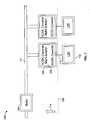
Fig. 3 shows the DC low voltage distribution system 300 according to the first aspect of the present invention in the application environment of an LED lighting system. The DC low voltage distribution system 300 comprises an AC/DC converter 306 which is connected tomains power 304. According to the present invention, a DC low voltage power distribution unit 316 (which in the following will also be referred to as "distribution unit" or "junction box") is connected via aninput connector 318 to an output of the AC/DC converter 306. Thedistribution unit 316 comprises a plurality ofoutput connectors 320 which are each outputting a DC power compliant to UL class 2. According to the present invention, the DCpower distribution unit 316 comprises an electric distribution circuit (not shown in this Figure) that distributes the input power from theinput connector 318 to be output by theoutput connectors 320. The electric distribution circuit according to the present invention will be explained in more detail below with reference toFig. 10 . - The AC/
DC converter 306 and thedistribution unit 316 are fitted inside aregular UL class 1type enclosure 310 which is arranged behind a partition wall or ceiling 308 or the like. As indicated by thearrow 314, all installations behind that partition wall 308 have to be installed by a qualified installer. - However, the
LEDs 302 as well asconverter 322 may be connected and exchanged without any further safety restrictions as all connections below separation line 308 are deemed safe for humans by UL Class 2 as well as SELV - An armored cable or
cable conduit 312 connects the AC/DC converter 306 to themains voltage 304. According to the present invention, the AC/DC converter 306 may for instance be an SELV rated power supply which provides adequate isolation at its output, either in the form of double reinforced isolation or other. - According to the present invention, the
output connectors 320 are chosen to be connected with readily available UL approved cable assemblies and/or junction boxes. As schematically shown inFigure 3 , a plurality ofLEDs 302 is connected each to their separate DC/DC converter 322 for driving and control. As will become apparent fromFig. 5 to 9 , however, theoutput connectors 320 may of course be connected to any other DC load, such as USB converters for USB power delivery, cell phone chargers, laptops, printers, DECT phones, and the like, either directly or by means of a suitable DC/DC converter, depending on the application Furthermore, also splitters and bus bars may be connected to theoutput connectors 320 to divide the maximum power as defined by UL class 2 over multiple loads - Compared to
Fig. 1 , thedistribution unit 316 reduces the amount of AC/DC converters which are needed to only one AC/DC converter 306. Moreover, thedistribution unit 316 essentially performs a conversion of the lighting installation from beingUL class 1 rated into being low voltage and UL class 2 compliant. Hence, theoutputs 320 are inherently safe. The term "inherently safe" means that a minimum hazard is involved in normal or reasonably foreseeable use of a product, device, or process. This requirement is for instance fulfilled by class 2 rated power supplies that output a maximum voltage of 60 Vdc, a maximum current of 8 A, and a maximum power of 100 W, as defined by the current version of UL 1310. Other values may also be considered as inherently safe if the standard's requirements are changed. -
Fig. 4 shows a DC low voltagepower distribution system 400 according to a second aspect of the present invention. According to this embodiment, thedistribution unit 316 is housed within anenclosure 402 that is compliant toUL class 1. The power supply which is formed by an AC/DC converter 404 is installed behind a partition wall 308 in the same way as any ballast or LED driver, and is arranged within a standard enclosure as required byUL class 1. - The
distribution unit 316 is connected to the output of thepower supply 404 by means of an armored cable or a cable conduit. Consequently, theenclosure 402 also has to comply withUL class 1 requirement, while theoutput connectors 320 comply with UL class 2. As indicated by thearrow 314, the armored cable (or the cable conduit) has to be installed by a qualified installer and may be connected with aterminal block 318. - A plurality of
LEDs 302 with their drivers and control units (indicated by the DC/DC converters 322), are connected to theoutput connectors 320 in order to form a lighting system. - As in the first embodiment, the
output connectors 320 output an inherently safe DC low voltage. Instead of providing power to theLEDs 302 theseoutput connectors 320 can also be connected to other DC loads. -
Fig. 5 shows the application of the DC low voltagepower distribution unit 316 according to the present invention in the application environment of a so-called LVDC (low voltage direct current)grid 500. The architecture ofFig. 5 is essentially based on the architecture shown inFig. 4 . In particular, aUL class 1 ratedpower supply 404 is connected to mains power (not visible in the Fig.). The output of thepower supply 404 is connected by means of an armored cable or atcable conduit 312 to theinput connector 318 of thedistribution unit 316.Output connectors 320 provide an inherently safe output power that is rated according to UL class 2. According to the most recent version of UL1310, 6th edition, August 26, 2011, this means that the power which is output is limited to the maximum value of 100 VA and the current is limited to a maximum current of 8 A. - In contrast to the architecture shown in
Fig. 4 , not only single LEDs may be connected to these inherentlysafe output connectors 320.Fig. 5 schematically shows some alternative connection schemes. Firstly, anadditional splitter 502 can be provided that is connected to one inherentlysafe output connector 320 in order to provide DC power tofurther LEDs 302 via respective DC/DC converters 322. Furthermore, alsoLEDs 504 with a smart socket can be connected either directly to one of theoutput connectors 320 or to the output of thesplitter 502. As this is well known in the art, smart sockets are electronic units that allow the direct control of an LED for instance by means of a cell phone or the like. - Furthermore, also LEDs and/or
LED holders 506 with integrated DC driver electronics may of course be used. - As shown in
Fig. 5 , thepower distribution unit 316 may furthermore be connected to abus bar 508 having a plurality ofdistribution nodes 510. Eachdistribution node 510 may be connected to a lighting unit comprising a DC/DC converter 322 and anLED 302. - The
output connectors 320 of thepower distribution unit 316 are also suitable for being connected to a DC/DC converter 512 which is configured for USB power delivery. The DC/DC converter 512 may for instance supply power to a USB-C device 514. - In addition to the above lighting and charging applications, any other DC loads can also be powered within the
LVDC grid 500 according to the present invention. For instance, anoccupancy sensor 516 and atemperature sensor 518 may be connected to one of theoutput connectors 320.Energy harvesting sensors 526 or any other kind of sensor may also be connected to the system. - Furthermore, also wireless communication bridges can be connected to one of the
output connectors 320. For instance, a Wi-Fi toDALI bridge 520 can be provided for receiving control signals according to the DALI communication standard. Alternatively or additionally, a Zigbee, a Bluetooth bridge, or any otherwireless communication bridge 522 may also be provided. The wireless communication may be performed via theCloud 524, as this is generally known in the art. The protocols mentioned are examples and may also include low power Bluetooth, proprietary or open protocols. -
Fig. 6 shows a further embodiment of a DC low voltagepower distribution system 600 according to the present invention. According to this embodiment, apower supply 306 and apower distribution unit 316 are contained within aUL class 1enclosure 310. Thepower supply 306 is connected tomains power 304 via anoptional switch 602. -
Output connectors 320 provide inherently safe DC low power to a plurality of DC load units. For instance, abus bar 508 with a plurality ofdistribution nodes 510 may be connected to one of theoutput connectors 320. One of the load units connected to thedistribution nodes 510 may for instance be aZigbee controller 522 that is connected to anLED 302 or another DC load which is controlled by thewireless Zigbee controller 522. - Another DC load unit that may be connected to a
distribution node 510 is a DC/DC converter 512 for aUSB device 514. Furthermore, as already mentioned above with respect toFig. 5 , a DC load unit may comprise an integrated lighting fixture, such as anLED 506 with an integrated CV to CC driver. As already mentioned above, theLEDs 302 may of course also be coupled directly via their DC/DC converters 322 to one of theoutput connectors 320. Furthermore,Fig. 6 also shows asplitter 502, in particular a 6-way distributor, which is connected to one of theoutput connectors 320 as the DC load unit. Each of the outputs of thissplitter 502 may for instance be connected to the CV to CC driver, forming a DC/DC converter 522 which in turn is connected to anLED 302. -
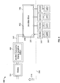
Figure 7 shows a further embodiment of a DC low voltage power distribution system 700 based on the arrangement ofFig. 3 and6 . Apower supply 306 which is connected via aswitch 602 tomains power 304 is arranged together with thedistribution unit 316 within an enclosure 310 (rated UL class 1). - The
output connectors 320 can be connected to similar DC load units as shown in the previous Figures. In addition to the architecture ofFig. 6 , thedistribution unit 316 further comprises aDALI connector 702 for connecting aDALI controller 704 to thedistribution unit 316. ThisDALI controller 704 is powered bymains power 304 and can be accessed by auser interface 706 such as a switch, dimmer, or the like. - DALI (digital addressable lighting interface) is a data protocol and transport mechanism that was jointly developed and specified by several manufacturers of lighting equipment. The common platform of DALI enables equipment from different manufacturers to be connected together. Usually, a DALI network consists of a controller and lighting devices that have DALI interfaces. The
controller 704 monitors and controls each light by means of a bidirectional data exchange. The DALI protocol permits devices to be individually addressed and controlled. DALI requires a single pair of wires to form the bus for communication to all devices on the DALI network. The DALI system is not classified as SELV and therefore may be run next to the mains cable or within a multicore cable that includes mains power. A DALI network requires a 24 V DC 250 mA power supply to operate. - According to the present invention, a DALI
controllable LED module 708 is connected to at least one of theoutput connectors 320. Alternatively, alsoconventional LEDs 302 can be connected to aDALI LED controller 710. -
Fig. 8 shows an architecture which is based on the concept ofFig. 4 where an armored cable orcable conduit 312 is connected to theinput connector 318 of thedistribution unit 316. AnSELV power supply 404 is outputting an output voltage of 60 V DC maximum to thedistribution unit 316. Thepower supply 404 is connected via apower supply switch 602 tomains power 304. The DC load units that can be connected to thevarious output connectors 320 essentially correspond to those explained with reference toFig. 6 . The respective explanations will not be reiterated here. - The arrangement of
Fig. 8 can be further extended in order to provide DALI functionality. Such an architecture is shown inFig. 9 . Thedistribution unit 316 does not only have aninput connector 318 for being connected to an armored cable orcable conduit 312, but also has aDALI connector 702 that provides the connection to theuser interface 706 and theDALI controller 704. As explained with reference toFig. 7 , theDALI controller 704 is connected tomains power 304. - The armored cable or
cable conduit 312 connects the input connected 318 topower supply 404 which in turn is connected via theswitch 602 tomains power 304. As already mentioned with respect toFig. 7 , one or moreDALI LED controllers 710 and/or DALIcontrollable LED modules 708 are connected to theoutput connectors 320 of thedistribution unit 316. - According to the present invention, the DC
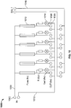
power distribution unit 316 comprises an electric distribution circuit that distributes the input power from theinput connector 318 to be output by theoutput connectors 320.Fig. 10 illustrates such adistribution circuit 1000 according to the present invention. As shown inFig. 10 , theelectric distribution circuit 1000 comprises twoinput terminals 1002 for being connected to theinput connector 318. An input line 1004 (which is for instance connected to positive potential) branches off into a plurality ofoutput lines 1006 withoutput terminals 1008 that are connected to theoutput connectors 320. - According to the present invention, each of the
output lines 1006 is provided with current limitingmeans 1010 which ensure that the power provided at the output terminals stays within the limits of UL class 2. In particular, it must be ensured that the current does not exceed 8 A as specified by UL1310. The current limitingmeans 1010 may for instance comprise glass fuses, thermal fuses, automatic fuses, or electric circuits that are designed to limit the output current and power. - In order to be able to monitor the status of the current limiting
means 1010, eachoutput line 1006 is connected via a resistor and asignaling LED 1014 to thereference line 1012. In case thefuse 1010 has been destroyed, thesignaling LED 1014 is no longer powered and therefore does not emit light. It is clear for a person skilled in the art, however, that any other suitable signaling means can also be used for monitoring the status of the current limitingmeans 1010. - According to the embodiment shown in
Fig. 10 , theelectric distribution circuit 1000 also comprises the twowires 1016 that are necessary for a DALI control according to the embodiment ofFigures 7 and9 . -
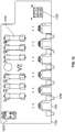
Fig. 11 shows an example of a printed circuit board (PCB) 1100 realizing theelectric distribution circuit 1000. Theoutput connectors 320 are formed by conventional PCB connectors. Glass fuses form the current limitingmeans 1010. Aterminal block 1102 is provided for connecting theinput connector 318. A plurality of signalingLEDs 1014 are arranged in a way that they can stay visible when mounting the printedcircuit board 1100 in a housing (not shown in the Figures). - Furthermore, the
fuses 1010 are arranged in a way that they are accessible for a facilitated exchange in case of a fault. -
Fig. 12 shows the embodiment of a printed circuit board forming theelectric distribution circuit 1000. According to this embodiment, surface mount technology is used for attaching the output connector to the PCB. Moreover, aDALI connector 1202 is provided for attaching the DALI wires. The other components correspond to those shown inFig. 11 . - As mentioned above, the present invention provides a DC low voltage power distribution unit for a power grid preferably for a building, said DC low voltage power distribution unit comprising at least one input connector for connecting the power distribution unit to a DC power supply, an electric distribution circuit comprising an input line connected to said input connector, and a reference potential line, said input line branching off into a plurality of output lines, said electric distribution circuit comprising current limiting means in each of said output lines, wherein a current limit value is provided by said current limiting means to limit an output power to be output at each of said output lines to an inherently safe value; and a plurality of output connectors connected to said output lines and to said reference potential line, wherein each of the output connectors are configured for outputting low DC voltage to a DC load.
- The present invention is based on the idea that by limiting the output power to an inherently safe value, the DC low voltage power distribution unit can serve as a converter between UL class 2 which has to be complied with at the output towards the lighting units and
UL class 1 which has to be met by the mains installations. In particular, UL1310 presently requires that the output power is limited to 100 VA and the maximum current is limited to 8 A. - The following Table 1 compares the requirements regarding maximum voltage, isolation, maximum current, and maximum power for the various standards mentioned above and the system according to an exemplary aspect of the present invention.
Table 1 SELV (IEC) UL class 2 EMerge Alliance LVDC of this invention USB-C Voltage (max) 60 Vdc 60 Vdc 24 Vdc 48 Vdc 20 Vdc Isolation double reinforced double reinforced double reinforced double reinforced double reinforced Current (max) N/A 8 A 4.1 A 2 A (fused) 5 A Power (max) N/A 100 W 100 W appr. 100 W 100 W - As can be seen from this overview, the DC low voltage distribution system according to the present invention can be designed in a way that it meets all existing requirements mentioned above.
- An advantage of the architecture according to the present invention can be seen in the fact that any off-the-shelf SELV rated power supply, or power supply not specified as SELV but with similar performance with respect to output voltage and isolation class as SELV, can be converted into a plurality of UL class 2 rated outputs in a cost efficient and flexible way. Based on the fact that many off-the-shelf power supplies can be used, this invention makes use of commercially and globally available components and only adds functionality to ensure that all outputs are UL class 2 compliant.
- The resulting outputs can be used in either EMerge Alliance compliant installations or in any other UL class 2 installations. Every output can be used to power one or more low-voltage lighting fixtures up to the limits as set forth by UL class 2. Moreover, as LVDC is taking off in more areas than just lighting, the present invention also aims at powering non-lighting devices, such as USB-C (USB-PD) over the output of a simple and compact DC/DC converter. The resulting power distribution network can be used for powering a vast array of sensors, switches, and gateways (i. e. to convert Wi-Fi into the Zigbee or Zigbee into DALI) because DC/DC conversion is often cheaper, smaller and more efficient than AC/DC conversion. Therefore, the LVDC network is more flexible and lower in installation costs than known networks such as the one proposed by the EMerge Alliance.
- According to an advantageous embodiment, said current limiting means comprise at least one glass fuse, thermal fuse, or automatic fuse or a circuit designed to limit the output current and power. Essentially, any type of fuse or current limiting circuitry can be used for limiting the current in the DC low voltage power distribution unit according to the present invention. Glass fuses have the advantage that they are cheap, small, simple to install and fast. However, they have to be replaced if they have become defective due to overloading or short-circuiting. Consequently, automatic fuses, such as magneto-thermal fuses, can be used which have the advantage that they can be re-activated after a fault. Furthermore, also polymeric positive temperature coefficient fuses can be advantageously used as resettable fuses. It is clear for a person skilled in the art that any kind of single tripping or resettable fuses can advantageously be employed in the DC low voltage distribution unit according to the present invention. Moreover, the current limiting means can also be configured in a way that the current limit value provided by said current limiting means is adjustable. In particular, this value can be adjusted according to the actual standard's requirements if these requirements are changed without much effort.
- According to another embodiment, said input connector is configured to be connected to a power supply with a voltage limited to a specified low voltage and with specified safety isolation. In particular, the input connector may be connected to a power supply with a voltage limited to the UL1310 specified voltage as well as the safety isolation as specified by UL 1310. Such power supply devices are commonly known as safety extra low voltage (SELV) AC/DC converters. However, as the basic function of this power supply can be seen in the voltage limitation and the isolation requirements, also non-SELV rated power supplies could be compliant.
- Moreover, the input connector may be configured to be connected to an armored cable or a cable conduit. This solution is advantageous for an embodiment where the DC low voltage power distribution unit is directly connected to a power supply that has to comply with
UL class 1. In case that the DC low voltage power distribution unit is supplied from an AC/DC converter which is integrated in acommon UL class 1 enclosure, the interconnection between the AC/DC converter and the distribution unit does not have to meet the requirements ofUL class 1. Consequently, the input connector does not have to be connectable to an armored cable or cable conduit. - In order to facilitate maintenance and repair of the DC low voltage power distribution system, signaling means may be provided for indicating a status of said current limiting means. These signaling means may comprise a plurality of light emitting diodes, LED, each being connected between said current limiting means and said output connector, for optically indicating said status. Such LEDs are cheap to be installed and effective for identifying a defective fuse. However, of course also other than optical signaling means may be provided. In particular, also a communication signal can be sent to a controller, if the DC low voltage power distribution unit is equipped with a communication bus, such as a DALI communication bus.
- By providing a communication bus line at the electric distribution circuit for being connected to a lighting interface controller, the DC low voltage power distribution unit according to the present invention can be integrated into a communication network that allows a central control of DC loads, such as lighting units.
- According to an advantageous embodiment of the present invention, a DC low voltage power distribution system further comprises a plurality of DC load units that are connected with said output connectors via mating load connectors. Such DC load units may preferably be attached to the DC low voltage power distribution unit by means of plug connectors. Thereby a flexible architecture can be achieved easily. In particular, the DC load units may comprise lighting units, such as LED luminaires or power converting units for powering a DC load. For instance, a USB converter can be provided which is configured for USB power delivery. The DC load units according to the present invention may of course interface any other DC load, including cell phones to be charged, laptops, printers, or DECT phones to be powered.
- Furthermore, in order to still enhance the flexibility of the system architecture, the system according to the present invention may further comprise at least one splitter and/or bus bar for further distributing the DC power output at said output connectors.
- The DC low voltage power distribution system according to the present invention may advantageously be configured to be mounted at a ceiling, a wall, or other part of building installation of said building. Of course, the DC low voltage power distribution system according to the present invention may also be mounted behind pieces of furniture such as kitchen cupboards or partition walls for office desks.
- The present invention has been described above with reference to installations in the US. However, for a person skilled in the art it is clear that the system according to the present invention is also applicable for Europe and the rest of the world, even if there is no need for armored cables or cable conduits carrying the mains power.
REFERENCE NUMERALS Reference Numeral Description 100 Conventional DC low voltage power distribution system in the US 102 LED 104 Mains power 106 AC/DC converter 108 Partition 112 Armored cable or cable conduit 114 Arrow indicating requirement of qualified installer 116 Connection 200 Conventional DC low voltage power distribution system in Europe 202 LED 204 Mains power 206 AC/DC converter 300 DC low voltage power distribution system 302 LED 304 Mains power 306 AC/DC converter 308 Partition 310 Enclosure 312 Armored cable or cable conduit 314 Arrow indicating the requirement of qualified installer 316 DC low voltage power distribution unit 318 Input connector 320 Output connector 322 DC/DC converter for LED 400 DC low voltage power distribution system 402 Enclosure 404 AC/DC converter, power supply 500 LVDC grid 502 Splitter 504 LED with smart socket 506 LED with integrated DC driver electronics 508 Bus bar 510 Distribution node 512 DC/DC converter for USB 514 USB-C device 516 Occupancy sensor 518 Temperature sensor 520 WIFI2DALI bridge 522 Zigbee or Bluetooth bridge 524 Cloud 600 DC low voltage power distribution system 602 Switch 700 DC low voltage power distribution system 702 DALI connector 704 DALI controller 706 User interface 708 DALI controllable LED module 710 DALI LED controller 1000 Electric distribution circuit 1002 Input terminals 1004 Input line 1006 Output line 1008 Output terminals 1010 Current limiting means 1012 Reference line 1014 Signaling LED 1016 DALI wires 1100 Printed circuit board (PCB) 1102 Terminal block 1202 DALI connector
Claims (10)
- DC low voltage power distribution system (300; 400) for a power grid, said DC low voltage power distribution system (300; 400) comprising
a DC low voltage power distribution unit (316) for the power grid,
an AC/DC converter (306; 404) having an input and an output, wherein the input is configured to be connected to a mains voltage (304);
characterized in that
said DC low voltage power distribution unit (316) comprises:at least one input connector (318) adapted to connect the DC low voltage power distribution unit (316) to a safety extra low voltage, SELV;an electric distribution circuit (1000) comprising a printed circuit board (1100) with two input terminals (1002) connected to the at least one input connector (318), the two input terminals (1002) comprising an input line (1004) and a reference potential line (1012), said input line (1004) branching off into a plurality of output lines (1006), said electric distribution circuit (1000) comprising current limiting means (1010) provided in each output line of said plurality of output lines (1006), wherein a current limit value of said current limiting means (1010) is provided to limit an output power to be output at each output line of said plurality of output lines (1006) to an inherently safe value, which is UL Class 2 compliant;a plurality of output connectors (320) respectively connected to said plurality of output lines (1006) and to said reference potential line (1012), wherein each output connector of the plurality output connectors (320) is configured for outputting DC low voltage, anda communication bus line (1016) adapted to be connected to a lighting interface controller (704) and further connected to each of the plurality of output connectors (320),wherein the AC/DC converter (306; 404) is configured to convert the mains voltage (304) into the safety extra low voltage, SELV, wherein the DC low voltage power distribution unit (316) is connected via the at least one input connector (318) to the output of the AC/DC converter (306; 404), thereby receiving the safety extra low voltage, SELV. - DC low voltage power distribution system according to claim 1, wherein each of said current limiting means (1010) comprise at least one glass fuse, thermal fuse, or automatic fuse or a circuit designed to limit the output current and power.
- DC low voltage power distribution system according to one of the preceding claims, wherein said at least one input connector (318) is connected via an armored cable or a cable conduit (312) to the AC/DC converter (404).
- DC low voltage power distribution system according to one of the preceding claims, further comprising signaling means (1014) adapted to indicate a status of said current limiting means (1010).
- DC low voltage power distribution system according to claim 4, said signaling means (1014) comprising a plurality of light emitting diodes, LED, each of the plurality of LEDs being connected between said current limiting means (1010) and one respective connector of the plurality of output connectors (320), and adapted to optically indicate said status.
- DC low voltage power distribution system according to one of the preceding claims, further comprising a plurality of DC load units, wherein each of the DC load units has a mating load connector that is connected with a respective one of said output connectors (320).
- DC low voltage power distribution system according to claim 6, wherein at least one of said DC load units comprises at least one lighting unit.
- DC low voltage power distribution system according to claim 6 or 7, wherein at least one of said DC load units comprises a power converting unit adapted to power a DC load.
- DC low voltage power distribution system according to one of the preceding claims, further comprising at least one splitter and/or bus bar adapted to further distribute the DC power output at said output connectors.
- DC low voltage power distribution system according to one of the preceding claims, said system being configured to be mounted at a ceiling, a wall, or other part of building installation of a building.
Priority Applications (3)
| Application Number | Priority Date | Filing Date | Title |
|---|---|---|---|
| EP15165574.3A EP3089552B1 (en) | 2015-04-29 | 2015-04-29 | Dc low voltage power distribution unit and system for a power grid |
| PCT/EP2016/059491 WO2016174138A1 (en) | 2015-04-29 | 2016-04-28 | Dc low voltage power distribution unit and system for a power grid |
| US15/797,468 US11043806B2 (en) | 2015-04-29 | 2017-10-30 | DC low voltage power distribution unit and system for a power grid |
Applications Claiming Priority (1)
| Application Number | Priority Date | Filing Date | Title |
|---|---|---|---|
| EP15165574.3A EP3089552B1 (en) | 2015-04-29 | 2015-04-29 | Dc low voltage power distribution unit and system for a power grid |
Publications (2)
| Publication Number | Publication Date |
|---|---|
| EP3089552A1 EP3089552A1 (en) | 2016-11-02 |
| EP3089552B1 true EP3089552B1 (en) | 2021-03-31 |
Family
ID=53039295
Family Applications (1)
| Application Number | Title | Priority Date | Filing Date |
|---|---|---|---|
| EP15165574.3A Active EP3089552B1 (en) | 2015-04-29 | 2015-04-29 | Dc low voltage power distribution unit and system for a power grid |
Country Status (3)
| Country | Link |
|---|---|
| US (1) | US11043806B2 (en) |
| EP (1) | EP3089552B1 (en) |
| WO (1) | WO2016174138A1 (en) |
Families Citing this family (2)
| Publication number | Priority date | Publication date | Assignee | Title |
|---|---|---|---|---|
| US11251645B2 (en) * | 2020-01-24 | 2022-02-15 | Dell Products, L.P. | Multimode USB-C power transmission and conversion supporting improved battery charging |
| CN117716168A (en) * | 2021-08-31 | 2024-03-15 | 松下知识产权经营株式会社 | Circuit device and lighting device |
Citations (1)
| Publication number | Priority date | Publication date | Assignee | Title |
|---|---|---|---|---|
| AU2013204215A1 (en) * | 2013-04-12 | 2014-10-30 | Schneider Electric (Australia) Pty Limited | Electronic lighting controller |
Family Cites Families (10)
| Publication number | Priority date | Publication date | Assignee | Title |
|---|---|---|---|---|
| CN2086003U (en) * | 1991-01-28 | 1991-10-02 | 刘晓路 | Means for indicating condition of fuse |
| US6694438B1 (en) * | 1999-07-02 | 2004-02-17 | Advanced Energy Industries, Inc. | System for controlling the delivery of power to DC computer components |
| CN201191930Y (en) * | 2007-11-14 | 2009-02-04 | 卢汉雄 | DC low voltage distribution box used for indoor LED illumination |
| AU2010201221A1 (en) * | 2009-03-31 | 2010-10-14 | Faraday Pty Ltd Shielding & Design | Lighting system and lighting assembly |
| EP2425432A4 (en) * | 2009-04-30 | 2015-05-13 | Green Plug Inc | Multi-functional bi-directional communication and bias power architecture for power supply control |
| US20150207316A1 (en) * | 2012-08-16 | 2015-07-23 | Robert Bosch Gmbh | Dc building system with energy storage and control system |
| CN202941009U (en) * | 2012-11-14 | 2013-05-15 | 塞里克鲁能源科技江苏有限公司 | Electricity larceny prevention and power saving type passageway sound and light operated illumination system |
| US9847628B2 (en) * | 2012-12-30 | 2017-12-19 | Zachary Leonid Braunstein | Plug and power distribution and control apparatus |
| US9478982B2 (en) * | 2013-07-22 | 2016-10-25 | Linear Technology Corporation | Power supply system and method |
| EP2846611B1 (en) * | 2013-09-06 | 2015-12-23 | Tridonic GmbH & Co. KG | Driver circuit for a light source and method of transmitting data over a power line |
-
2015
- 2015-04-29 EP EP15165574.3A patent/EP3089552B1/en active Active
-
2016
- 2016-04-28 WO PCT/EP2016/059491 patent/WO2016174138A1/en not_active Ceased
-
2017
- 2017-10-30 US US15/797,468 patent/US11043806B2/en not_active Expired - Fee Related
Patent Citations (1)
| Publication number | Priority date | Publication date | Assignee | Title |
|---|---|---|---|---|
| AU2013204215A1 (en) * | 2013-04-12 | 2014-10-30 | Schneider Electric (Australia) Pty Limited | Electronic lighting controller |
Also Published As
| Publication number | Publication date |
|---|---|
| WO2016174138A1 (en) | 2016-11-03 |
| US20180069397A1 (en) | 2018-03-08 |
| US11043806B2 (en) | 2021-06-22 |
| EP3089552A1 (en) | 2016-11-02 |
Similar Documents
| Publication | Publication Date | Title |
|---|---|---|
| US7671544B2 (en) | System and architecture for controlling lighting through a low-voltage bus | |
| US12150222B2 (en) | System for distributing DC power to and controlling building devices | |
| US12004282B2 (en) | Hybrid dimming controller with multi-class outputs | |
| US8502470B2 (en) | DC distribution system | |
| EP2885572A2 (en) | Light fixture having power over ethernet power sourcing equipment | |
| JP2011519144A (en) | Multiple configurable lighting and energy control systems and modules | |
| EP3149823A1 (en) | Distributed low voltage power systems | |
| EP3089552B1 (en) | Dc low voltage power distribution unit and system for a power grid | |
| US20180301908A1 (en) | Driver with Pass-Through AC Outlet | |
| US7157860B2 (en) | Control device for flashlight systems in airports | |
| US7511945B2 (en) | Electrical distribution system | |
| JP2008043000A (en) | Dc power distribution system | |
| CN100536633C (en) | Control gear for multiple lamp operation | |
| KR20160089002A (en) | Power and communication integration wiring apparatus using power plexer | |
| KR101433190B1 (en) | Power and communication integration wiring apparatus using power plexer | |
| JP7637850B2 (en) | Lighting Control System | |
| AU2011101272A4 (en) | Data distribution apparatus | |
| CN211981339U (en) | Prefabricated type power distribution system | |
| WO2013128382A1 (en) | Power distribution track system having separate ac and dc conductors, electric load therefor having ac/dc converter | |
| AU2013100509A4 (en) | Easy connect power control module | |
| KR101444900B1 (en) | Power and communication integration wiring apparatus using power plexer | |
| EP3099972B1 (en) | Grouping lighting units | |
| US9795011B2 (en) | LED lighting system driven at high voltage DC | |
| GB2613141A (en) | Lighting system | |
| KR20220004250A (en) | Power and communication integration wiring apparatus using power plexer |
Legal Events
| Date | Code | Title | Description |
|---|---|---|---|
| PUAI | Public reference made under article 153(3) epc to a published international application that has entered the european phase |
Free format text: ORIGINAL CODE: 0009012 |
|
| AK | Designated contracting states |
Kind code of ref document: A1 Designated state(s): AL AT BE BG CH CY CZ DE DK EE ES FI FR GB GR HR HU IE IS IT LI LT LU LV MC MK MT NL NO PL PT RO RS SE SI SK SM TR |
|
| AX | Request for extension of the european patent |
Extension state: BA ME |
|
| STAA | Information on the status of an ep patent application or granted ep patent |
Free format text: STATUS: REQUEST FOR EXAMINATION WAS MADE |
|
| 17P | Request for examination filed |
Effective date: 20170502 |
|
| RBV | Designated contracting states (corrected) |
Designated state(s): AL AT BE BG CH CY CZ DE DK EE ES FI FR GB GR HR HU IE IS IT LI LT LU LV MC MK MT NL NO PL PT RO RS SE SI SK SM TR |
|
| STAA | Information on the status of an ep patent application or granted ep patent |
Free format text: STATUS: EXAMINATION IS IN PROGRESS |
|
| 17Q | First examination report despatched |
Effective date: 20190715 |
|
| REG | Reference to a national code |
Ref country code: DE Ref legal event code: R079 Ref document number: 602015067385 Country of ref document: DE Free format text: PREVIOUS MAIN CLASS: H05B0033080000 Ipc: H05B0045370000 |
|
| GRAP | Despatch of communication of intention to grant a patent |
Free format text: ORIGINAL CODE: EPIDOSNIGR1 |
|
| STAA | Information on the status of an ep patent application or granted ep patent |
Free format text: STATUS: GRANT OF PATENT IS INTENDED |
|
| RIC1 | Information provided on ipc code assigned before grant |
Ipc: H05B 45/37 20200101AFI20201021BHEP |
|
| INTG | Intention to grant announced |
Effective date: 20201110 |
|
| GRAS | Grant fee paid |
Free format text: ORIGINAL CODE: EPIDOSNIGR3 |
|
| GRAA | (expected) grant |
Free format text: ORIGINAL CODE: 0009210 |
|
| STAA | Information on the status of an ep patent application or granted ep patent |
Free format text: STATUS: THE PATENT HAS BEEN GRANTED |
|
| AK | Designated contracting states |
Kind code of ref document: B1 Designated state(s): AL AT BE BG CH CY CZ DE DK EE ES FI FR GB GR HR HU IE IS IT LI LT LU LV MC MK MT NL NO PL PT RO RS SE SI SK SM TR |
|
| REG | Reference to a national code |
Ref country code: GB Ref legal event code: FG4D Ref country code: CH Ref legal event code: EP |
|
| REG | Reference to a national code |
Ref country code: DE Ref legal event code: R096 Ref document number: 602015067385 Country of ref document: DE Ref country code: AT Ref legal event code: REF Ref document number: 1378447 Country of ref document: AT Kind code of ref document: T Effective date: 20210415 |
|
| REG | Reference to a national code |
Ref country code: IE Ref legal event code: FG4D |
|
| REG | Reference to a national code |
Ref country code: LT Ref legal event code: MG9D |
|
| PG25 | Lapsed in a contracting state [announced via postgrant information from national office to epo] |
Ref country code: NO Free format text: LAPSE BECAUSE OF FAILURE TO SUBMIT A TRANSLATION OF THE DESCRIPTION OR TO PAY THE FEE WITHIN THE PRESCRIBED TIME-LIMIT Effective date: 20210630 Ref country code: BG Free format text: LAPSE BECAUSE OF FAILURE TO SUBMIT A TRANSLATION OF THE DESCRIPTION OR TO PAY THE FEE WITHIN THE PRESCRIBED TIME-LIMIT Effective date: 20210630 Ref country code: HR Free format text: LAPSE BECAUSE OF FAILURE TO SUBMIT A TRANSLATION OF THE DESCRIPTION OR TO PAY THE FEE WITHIN THE PRESCRIBED TIME-LIMIT Effective date: 20210331 Ref country code: FI Free format text: LAPSE BECAUSE OF FAILURE TO SUBMIT A TRANSLATION OF THE DESCRIPTION OR TO PAY THE FEE WITHIN THE PRESCRIBED TIME-LIMIT Effective date: 20210331 |
|
| PG25 | Lapsed in a contracting state [announced via postgrant information from national office to epo] |
Ref country code: SE Free format text: LAPSE BECAUSE OF FAILURE TO SUBMIT A TRANSLATION OF THE DESCRIPTION OR TO PAY THE FEE WITHIN THE PRESCRIBED TIME-LIMIT Effective date: 20210331 Ref country code: RS Free format text: LAPSE BECAUSE OF FAILURE TO SUBMIT A TRANSLATION OF THE DESCRIPTION OR TO PAY THE FEE WITHIN THE PRESCRIBED TIME-LIMIT Effective date: 20210331 Ref country code: LV Free format text: LAPSE BECAUSE OF FAILURE TO SUBMIT A TRANSLATION OF THE DESCRIPTION OR TO PAY THE FEE WITHIN THE PRESCRIBED TIME-LIMIT Effective date: 20210331 |
|
| REG | Reference to a national code |
Ref country code: NL Ref legal event code: MP Effective date: 20210331 |
|
| REG | Reference to a national code |
Ref country code: AT Ref legal event code: MK05 Ref document number: 1378447 Country of ref document: AT Kind code of ref document: T Effective date: 20210331 |
|
| PG25 | Lapsed in a contracting state [announced via postgrant information from national office to epo] |
Ref country code: LT Free format text: LAPSE BECAUSE OF FAILURE TO SUBMIT A TRANSLATION OF THE DESCRIPTION OR TO PAY THE FEE WITHIN THE PRESCRIBED TIME-LIMIT Effective date: 20210331 Ref country code: NL Free format text: LAPSE BECAUSE OF FAILURE TO SUBMIT A TRANSLATION OF THE DESCRIPTION OR TO PAY THE FEE WITHIN THE PRESCRIBED TIME-LIMIT Effective date: 20210331 Ref country code: EE Free format text: LAPSE BECAUSE OF FAILURE TO SUBMIT A TRANSLATION OF THE DESCRIPTION OR TO PAY THE FEE WITHIN THE PRESCRIBED TIME-LIMIT Effective date: 20210331 Ref country code: CZ Free format text: LAPSE BECAUSE OF FAILURE TO SUBMIT A TRANSLATION OF THE DESCRIPTION OR TO PAY THE FEE WITHIN THE PRESCRIBED TIME-LIMIT Effective date: 20210331 Ref country code: AT Free format text: LAPSE BECAUSE OF FAILURE TO SUBMIT A TRANSLATION OF THE DESCRIPTION OR TO PAY THE FEE WITHIN THE PRESCRIBED TIME-LIMIT Effective date: 20210331 Ref country code: SM Free format text: LAPSE BECAUSE OF FAILURE TO SUBMIT A TRANSLATION OF THE DESCRIPTION OR TO PAY THE FEE WITHIN THE PRESCRIBED TIME-LIMIT Effective date: 20210331 |
|
| PG25 | Lapsed in a contracting state [announced via postgrant information from national office to epo] |
Ref country code: IS Free format text: LAPSE BECAUSE OF FAILURE TO SUBMIT A TRANSLATION OF THE DESCRIPTION OR TO PAY THE FEE WITHIN THE PRESCRIBED TIME-LIMIT Effective date: 20210731 Ref country code: SK Free format text: LAPSE BECAUSE OF FAILURE TO SUBMIT A TRANSLATION OF THE DESCRIPTION OR TO PAY THE FEE WITHIN THE PRESCRIBED TIME-LIMIT Effective date: 20210331 Ref country code: RO Free format text: LAPSE BECAUSE OF FAILURE TO SUBMIT A TRANSLATION OF THE DESCRIPTION OR TO PAY THE FEE WITHIN THE PRESCRIBED TIME-LIMIT Effective date: 20210331 Ref country code: ES Free format text: LAPSE BECAUSE OF FAILURE TO SUBMIT A TRANSLATION OF THE DESCRIPTION OR TO PAY THE FEE WITHIN THE PRESCRIBED TIME-LIMIT Effective date: 20210331 Ref country code: PL Free format text: LAPSE BECAUSE OF FAILURE TO SUBMIT A TRANSLATION OF THE DESCRIPTION OR TO PAY THE FEE WITHIN THE PRESCRIBED TIME-LIMIT Effective date: 20210331 Ref country code: PT Free format text: LAPSE BECAUSE OF FAILURE TO SUBMIT A TRANSLATION OF THE DESCRIPTION OR TO PAY THE FEE WITHIN THE PRESCRIBED TIME-LIMIT Effective date: 20210802 |
|
| PG25 | Lapsed in a contracting state [announced via postgrant information from national office to epo] |
Ref country code: LU Free format text: LAPSE BECAUSE OF NON-PAYMENT OF DUE FEES Effective date: 20210429 |
|
| REG | Reference to a national code |
Ref country code: DE Ref legal event code: R097 Ref document number: 602015067385 Country of ref document: DE |
|
| REG | Reference to a national code |
Ref country code: BE Ref legal event code: MM Effective date: 20210430 |
|
| PG25 | Lapsed in a contracting state [announced via postgrant information from national office to epo] |
Ref country code: DK Free format text: LAPSE BECAUSE OF FAILURE TO SUBMIT A TRANSLATION OF THE DESCRIPTION OR TO PAY THE FEE WITHIN THE PRESCRIBED TIME-LIMIT Effective date: 20210331 Ref country code: AL Free format text: LAPSE BECAUSE OF FAILURE TO SUBMIT A TRANSLATION OF THE DESCRIPTION OR TO PAY THE FEE WITHIN THE PRESCRIBED TIME-LIMIT Effective date: 20210331 Ref country code: CH Free format text: LAPSE BECAUSE OF NON-PAYMENT OF DUE FEES Effective date: 20210430 Ref country code: LI Free format text: LAPSE BECAUSE OF NON-PAYMENT OF DUE FEES Effective date: 20210430 Ref country code: MC Free format text: LAPSE BECAUSE OF FAILURE TO SUBMIT A TRANSLATION OF THE DESCRIPTION OR TO PAY THE FEE WITHIN THE PRESCRIBED TIME-LIMIT Effective date: 20210331 |
|
| PLBE | No opposition filed within time limit |
Free format text: ORIGINAL CODE: 0009261 |
|
| STAA | Information on the status of an ep patent application or granted ep patent |
Free format text: STATUS: NO OPPOSITION FILED WITHIN TIME LIMIT |
|
| 26N | No opposition filed |
Effective date: 20220104 |
|
| PG25 | Lapsed in a contracting state [announced via postgrant information from national office to epo] |
Ref country code: IE Free format text: LAPSE BECAUSE OF NON-PAYMENT OF DUE FEES Effective date: 20210429 |
|
| PG25 | Lapsed in a contracting state [announced via postgrant information from national office to epo] |
Ref country code: IS Free format text: LAPSE BECAUSE OF FAILURE TO SUBMIT A TRANSLATION OF THE DESCRIPTION OR TO PAY THE FEE WITHIN THE PRESCRIBED TIME-LIMIT Effective date: 20210731 |
|
| PG25 | Lapsed in a contracting state [announced via postgrant information from national office to epo] |
Ref country code: IT Free format text: LAPSE BECAUSE OF FAILURE TO SUBMIT A TRANSLATION OF THE DESCRIPTION OR TO PAY THE FEE WITHIN THE PRESCRIBED TIME-LIMIT Effective date: 20210331 Ref country code: BE Free format text: LAPSE BECAUSE OF NON-PAYMENT OF DUE FEES Effective date: 20210430 |
|
| PG25 | Lapsed in a contracting state [announced via postgrant information from national office to epo] |
Ref country code: HU Free format text: LAPSE BECAUSE OF FAILURE TO SUBMIT A TRANSLATION OF THE DESCRIPTION OR TO PAY THE FEE WITHIN THE PRESCRIBED TIME-LIMIT; INVALID AB INITIO Effective date: 20150429 |
|
| PG25 | Lapsed in a contracting state [announced via postgrant information from national office to epo] |
Ref country code: CY Free format text: LAPSE BECAUSE OF FAILURE TO SUBMIT A TRANSLATION OF THE DESCRIPTION OR TO PAY THE FEE WITHIN THE PRESCRIBED TIME-LIMIT Effective date: 20210331 |
|
| PG25 | Lapsed in a contracting state [announced via postgrant information from national office to epo] |
Ref country code: GR Free format text: LAPSE BECAUSE OF FAILURE TO SUBMIT A TRANSLATION OF THE DESCRIPTION OR TO PAY THE FEE WITHIN THE PRESCRIBED TIME-LIMIT Effective date: 20210331 |
|
| PG25 | Lapsed in a contracting state [announced via postgrant information from national office to epo] |
Ref country code: MK Free format text: LAPSE BECAUSE OF FAILURE TO SUBMIT A TRANSLATION OF THE DESCRIPTION OR TO PAY THE FEE WITHIN THE PRESCRIBED TIME-LIMIT Effective date: 20210331 |
|
| PGFP | Annual fee paid to national office [announced via postgrant information from national office to epo] |
Ref country code: GB Payment date: 20240307 Year of fee payment: 10 |
|
| PGFP | Annual fee paid to national office [announced via postgrant information from national office to epo] |
Ref country code: FR Payment date: 20240308 Year of fee payment: 10 |
|
| PGFP | Annual fee paid to national office [announced via postgrant information from national office to epo] |
Ref country code: DE Payment date: 20240306 Year of fee payment: 10 |
|
| PG25 | Lapsed in a contracting state [announced via postgrant information from national office to epo] |
Ref country code: MT Free format text: LAPSE BECAUSE OF FAILURE TO SUBMIT A TRANSLATION OF THE DESCRIPTION OR TO PAY THE FEE WITHIN THE PRESCRIBED TIME-LIMIT Effective date: 20210331 |
|
| REG | Reference to a national code |
Ref country code: DE Ref legal event code: R119 Ref document number: 602015067385 Country of ref document: DE |
|
| PG25 | Lapsed in a contracting state [announced via postgrant information from national office to epo] |
Ref country code: TR Free format text: LAPSE BECAUSE OF FAILURE TO SUBMIT A TRANSLATION OF THE DESCRIPTION OR TO PAY THE FEE WITHIN THE PRESCRIBED TIME-LIMIT Effective date: 20210331 |
|
| GBPC | Gb: european patent ceased through non-payment of renewal fee |
Effective date: 20250429 |
|
| PG25 | Lapsed in a contracting state [announced via postgrant information from national office to epo] |
Ref country code: DE Free format text: LAPSE BECAUSE OF NON-PAYMENT OF DUE FEES Effective date: 20251104 |
|
| PG25 | Lapsed in a contracting state [announced via postgrant information from national office to epo] |
Ref country code: GB Free format text: LAPSE BECAUSE OF NON-PAYMENT OF DUE FEES Effective date: 20250429 |
|
| PG25 | Lapsed in a contracting state [announced via postgrant information from national office to epo] |
Ref country code: FR Free format text: LAPSE BECAUSE OF NON-PAYMENT OF DUE FEES Effective date: 20250430 |