EP3089531B1 - Terminal utilisateur et procédé de communication radio - Google Patents
Terminal utilisateur et procédé de communication radio Download PDFInfo
- Publication number
- EP3089531B1 EP3089531B1 EP14874819.7A EP14874819A EP3089531B1 EP 3089531 B1 EP3089531 B1 EP 3089531B1 EP 14874819 A EP14874819 A EP 14874819A EP 3089531 B1 EP3089531 B1 EP 3089531B1
- Authority
- EP
- European Patent Office
- Prior art keywords
- signals
- cell
- receiving
- resources
- terminals
- Prior art date
- Legal status (The legal status is an assumption and is not a legal conclusion. Google has not performed a legal analysis and makes no representation as to the accuracy of the status listed.)
- Active
Links
- 238000004891 communication Methods 0.000 title claims description 50
- 238000000034 method Methods 0.000 title claims description 30
- 230000001413 cellular effect Effects 0.000 claims description 18
- 230000005540 biological transmission Effects 0.000 description 22
- 238000010586 diagram Methods 0.000 description 20
- 238000012545 processing Methods 0.000 description 19
- 230000008054 signal transmission Effects 0.000 description 17
- 230000008569 process Effects 0.000 description 13
- 239000000969 carrier Substances 0.000 description 12
- 241000854291 Dianthus carthusianorum Species 0.000 description 7
- 238000013468 resource allocation Methods 0.000 description 6
- 238000013507 mapping Methods 0.000 description 5
- 238000006243 chemical reaction Methods 0.000 description 4
- 238000012384 transportation and delivery Methods 0.000 description 4
- 230000002776 aggregation Effects 0.000 description 3
- 238000004220 aggregation Methods 0.000 description 3
- 230000011664 signaling Effects 0.000 description 3
- 230000008901 benefit Effects 0.000 description 2
- 230000010267 cellular communication Effects 0.000 description 2
- 238000012937 correction Methods 0.000 description 2
- 238000005516 engineering process Methods 0.000 description 2
- 230000007774 longterm Effects 0.000 description 2
- 238000010295 mobile communication Methods 0.000 description 2
- 238000012544 monitoring process Methods 0.000 description 2
- 239000013307 optical fiber Substances 0.000 description 2
- 238000004590 computer program Methods 0.000 description 1
- 230000008878 coupling Effects 0.000 description 1
- 238000010168 coupling process Methods 0.000 description 1
- 238000005859 coupling reaction Methods 0.000 description 1
- 230000001419 dependent effect Effects 0.000 description 1
- 230000000694 effects Effects 0.000 description 1
- 238000007726 management method Methods 0.000 description 1
- 230000007246 mechanism Effects 0.000 description 1
- 238000012986 modification Methods 0.000 description 1
- 230000004048 modification Effects 0.000 description 1
- 230000006855 networking Effects 0.000 description 1
- 230000000737 periodic effect Effects 0.000 description 1
- 230000004044 response Effects 0.000 description 1
- 230000001360 synchronised effect Effects 0.000 description 1
Images


Classifications
-
- H—ELECTRICITY
- H04—ELECTRIC COMMUNICATION TECHNIQUE
- H04W—WIRELESS COMMUNICATION NETWORKS
- H04W72/00—Local resource management
- H04W72/04—Wireless resource allocation
- H04W72/044—Wireless resource allocation based on the type of the allocated resource
- H04W72/0453—Resources in frequency domain, e.g. a carrier in FDMA
-
- H—ELECTRICITY
- H04—ELECTRIC COMMUNICATION TECHNIQUE
- H04W—WIRELESS COMMUNICATION NETWORKS
- H04W48/00—Access restriction; Network selection; Access point selection
- H04W48/08—Access restriction or access information delivery, e.g. discovery data delivery
- H04W48/12—Access restriction or access information delivery, e.g. discovery data delivery using downlink control channel
-
- H—ELECTRICITY
- H04—ELECTRIC COMMUNICATION TECHNIQUE
- H04W—WIRELESS COMMUNICATION NETWORKS
- H04W52/00—Power management, e.g. TPC [Transmission Power Control], power saving or power classes
- H04W52/02—Power saving arrangements
- H04W52/0209—Power saving arrangements in terminal devices
- H04W52/0225—Power saving arrangements in terminal devices using monitoring of external events, e.g. the presence of a signal
- H04W52/0235—Power saving arrangements in terminal devices using monitoring of external events, e.g. the presence of a signal where the received signal is a power saving command
-
- H—ELECTRICITY
- H04—ELECTRIC COMMUNICATION TECHNIQUE
- H04W—WIRELESS COMMUNICATION NETWORKS
- H04W76/00—Connection management
- H04W76/10—Connection setup
- H04W76/14—Direct-mode setup
-
- H—ELECTRICITY
- H04—ELECTRIC COMMUNICATION TECHNIQUE
- H04W—WIRELESS COMMUNICATION NETWORKS
- H04W8/00—Network data management
- H04W8/005—Discovery of network devices, e.g. terminals
-
- Y—GENERAL TAGGING OF NEW TECHNOLOGICAL DEVELOPMENTS; GENERAL TAGGING OF CROSS-SECTIONAL TECHNOLOGIES SPANNING OVER SEVERAL SECTIONS OF THE IPC; TECHNICAL SUBJECTS COVERED BY FORMER USPC CROSS-REFERENCE ART COLLECTIONS [XRACs] AND DIGESTS
- Y02—TECHNOLOGIES OR APPLICATIONS FOR MITIGATION OR ADAPTATION AGAINST CLIMATE CHANGE
- Y02D—CLIMATE CHANGE MITIGATION TECHNOLOGIES IN INFORMATION AND COMMUNICATION TECHNOLOGIES [ICT], I.E. INFORMATION AND COMMUNICATION TECHNOLOGIES AIMING AT THE REDUCTION OF THEIR OWN ENERGY USE
- Y02D30/00—Reducing energy consumption in communication networks
- Y02D30/70—Reducing energy consumption in communication networks in wireless communication networks
Definitions
- the present invention relates to a user terminal, and a radio communication method in a next-generation mobile communication system.
- LTE Long Term Evolution
- FAA Full Radio Access
- 4G Full Radio Access
- D2D Device-to-Device technology
- D2D terminal In studying inter-terminal communication and discovery techniques (D2D communication/discovery), whether or not a terminal (D2D terminal) that performs D2D operations (transmission and reception of device-to-device signals, including D2D communication and D2D discovery) are present in the network coverage is one important precondition.
- WO 2012166969 A1 describes a hybrid user equipment and advanced user equipment data offloading architecture.
- the advanced user equipment includes a backhaul link to a telecommunication network and/or the Internet.
- the user equipment can send and receive data through the advanced user equipment using the backhaul link.
- US 20130308552 A1 describes a method, an apparatus, and a computer program product for wireless communication, in which a network entity may be operable to communicate D2D resource allocations to a UE supported by a HeNB.
- the network entity is operable to determine whether a HeNB is operable to communicate system information to a UE.
- system information may include, but is not limited to, D2D resource allocations, paging information, etc.
- the network entity determines that a HeNB is operable to communicate system information to a UE then it may transmit the system information to the HeNB to allow the HeNB to convey the system information to the UE.
- the network entity determines that a HeNB is not operable to communicate system information to a UE then it may transmit the system information to the UE via one or more other network entities.
- WO 2013/157438 A1 describes a wireless communication system, a communication control device, wireless communication terminals, and a communication control method that are said to enable direct communication between terminals (device-to-device communication) to be provided by using a radio access network such as a Long Term Evolution (LTE) network, while controlling the wireless communication terminals from the network side.
- a wireless base station provides notification of broadcast information, which represents whether direct communication is allowed, within a prescribed wireless communication area. Terminals begin direct communication on the basis of the broadcast information received from the wireless base station.
- the wireless base station transmits configuration information for the communication environment required for direct communication within the prescribed wireless communication area when direct communication is allowed, and the terminals configure the communication environment required for direct communication on the basis of the configuration information received from the communication control device.
- WO 2013182115 A1 describes a data transmission/receiving method and device.
- the described transmission method is applied to a base station, and comprises: allocating a network resource required for D2D communications for each UE in a UE group, and using the network resource as a component carrier of each UE, each UE supporting carrier aggregation; and dividing the data to be transmitted to the UE group into a plurality of pieces of component data information and respectively transmitting same to each UE, each UE sharing the plurality of pieces of component data information transmitted to each UE via the component carrier.
- the described method and device are said to allow the use of D2D technology in carrier aggregation.
- Non-patent Literature 1 "Key Drivers for LTE Success: Services Evolution," 2011 September, 3GPP, Internet URL: http://www.3gpp.org/ftp/Information/presentations/presentations_2011/201 1_09_LTE_Asia/2011_LTE-Asia_3GPP_Service_evolution. pdf
- D2D signals are transmitted and received in a network where multiple frequencies are in use, if a frequency carrier that does not have an expanded coverage is used as a D2D signal transmitting/receiving resource, this may result in the situation where many D2D stay outside the coverage, and there is a problem that D2D signals cannot be transmitted or received efficiently based on control from the network and the power consumption in D2D terminals increases.
- the present invention has been made in view of the above, and it is therefore an object of the present invention to provide a user terminal, a radio base station, a radio communication system and a radio communication method which can prevent the increase of power consumption in D2D terminals even when a frequency carrier that does not have an expanded coverage is used as a D2D signal transmitting/receiving resource where D2D signals are transmitted and received in a network in which multiple frequencies are in use.
- a user terminal that is capable of transmitting and receiving device-to-device signals, comprising a receiving section that receives system information, which is transmitted from the connecting or serving radio base station and which contains at least information about the resources for transmitting and receiving the device-to-device signals, and a control section that, based on the information about the device-to-device signal transmitting/receiving resources, executes control so that the device-to-device signals are transmitted and received in a second frequency carrier, which is different from a first frequency carrier, in which the information about the device-to-device signal transmitting/receiving resources is transmitted.
- the control section is configured to control a synchronization of the device-to-device signal transmitting/receiving resources, based on the system information.
- the user terminal is configured to, when a first cell and a second cell operate synchronously, synchronise the device-to-device signal transmitting/receiving resources by using synchronization signals of the first cell as a source of synchronization, and when the first cell and the second cell operate asynchronously and the user terminal detects synchronization signals of the second cell, to synchronise the device-to-device signal transmitting/receiving resources by using synchronization signals of the second cell as a source of synchronization.
- a radio communication method in a user terminal that is capable of transmitting and receiving device-to-device signals, the radio communication method comprising receiving system information, which is transmitted from a connecting or serving radio base station and which contains at least information about resources for transmitting and receiving the device-to-device signals; and based on the information about the device-to-device signal transmitting/receiving resources, executing control so that the device-to-device signals are transmitted and received by using resources in a second frequency carrier, which is different from a first frequency carrier, in which the information about the device-to-device signal transmitting/receiving resources is transmitted.
- the control comprises controlling a synchronization of the device-to-device signal transmitting/receiving resources, based on the system information.
- the user terminal When a first cell and a second cell operate synchronously, the user terminal synchronises the device-to-device signal transmitting/receiving resources by using synchronization signals of the first cell as a source of synchronization, and when the first cell and the second cell operate asynchronously, and the user terminal detects synchronization signals of the second cell, the user terminal synchronises the device-to-device signal transmitting/receiving resources by using synchronization signals of the second cell as a source of synchronization.
- the present invention even when a frequency carrier that does not have an expanded coverages is used as a D2D signal transmitting/receiving resource where D2D signals are transmitted and received in a network in which multiple frequencies are in use, it is still possible to transmit and receive D2D signals efficiently based on control from the network, and prevent the increase of power consumption in D2D terminals.
- periodic uplink resource groups are allocated to D2D terminals, semi-statically, as D2D signal transmitting/receiving resources.
- Each D2D terminal transmits signals using part of the D2D signal transmitting/receiving resources.
- each D2D terminal finds out other D2D terminals, communicates and so on by receiving signals transmitted from other D2D terminals among the D2D signal transmitting/receiving resources.
- FIG. 1A is a diagram to show an example in which D2D terminals are present in the coverage of a network.
- the radio base station controls the resources for use for the D2D terminals in the coverage and so on.
- the D2D terminals perform signal transmitting/receiving operations and so on based on control from the network.
- FIG. IB and FIG. 1C are diagrams to explain examples in which D2D terminals are present outside the network coverage.
- a given D2D terminal serves as the cluster head and controls the other D2D terminals.
- the other D2D terminals perform signal transmitting/receiving operations and so on based on control from the cluster head.
- D2D terminals are controlled individually in performing signal transmitting/receiving operations and so on.
- D2D terminals When D2D terminals are present in the network coverage and when D2D terminals are present outside the network coverage, varying use cases and operations of D2D communication apply.
- D2D signals are transmitted and received, for example, for commercial use cases -- that is, for allowing SNS (Social Networking Service) and advertisement distribution and so on by means of direct inter-terminal communication functions (proximity-based service).
- SNS Social Networking Service
- advertisement distribution and so on by means of direct inter-terminal communication functions (proximity-based service).
- proxy-based service the network controls the resources for use for the D2D terminals and so on.
- D2D signals are transmitted and received, for example, for securing public safety -- that is, for making urgent communication in times of disaster and so on. In this case, as described earlier, it is necessary to allow D2D terminals to operate autonomously, or apply control between terminals.
- LTE and LTE-advanced networks may be structured to accommodate multiple frequencies, not only a single frequency.
- a structure may be employed in which macro cells use a carrier of a relatively low frequency band such as 2 [GHz], and small cells use a carrier of a relatively high frequency band such as 3.5 [GHz].
- the coverage varies per frequency carrier.
- the macro cells achieve wide coverages by using a low frequency band carrier.
- macro cells operate in frequencies to which existing terminals of Rel. 8 to Rel. 11 and terminals of Rel. 12 can connect.
- Small cells are placed in a localized manner so as to cover heavy-traffic areas.
- a macro base station to form a macro cell and a small base station (not shown in FIG. 2 ) to form a small cell are connected via a backhaul link.
- the operation in which a macro base station and a small base stations are coordinated via backhaul and the macro base station assists the small base station -- that is, the operation in which a macro base station makes a small base station be dependent thereon -- may be assumed here. Also, between a plurality of small base stations, too, connection may be established via a backhaul link.
- uplink resources in the macro cell frequency may be used for existing terminals of Rel. 8 to Rel. 11 and terminals of Rel. 12, for VoIP (Voice over Internet Protocol) and so on. Consequently, uplink resources in the macro cell frequency leave little room, and are therefore inadequate to use as D2D signal transmitting/receiving resources.
- small cells unlike macro cells, do not have expanded coverage. Consequently, as show in FIG. 2 , the situation might occur where many D2D terminals that are present within a macro cell's coverage are present outside small cell coverages.
- the small cell frequency is used as a D2D signal transmitting/receiving resource, many D2D terminals operate as when they are present outside the coverages.
- a D2D terminal identifies itself as the cluster head and controls the resources of other D2D terminals. The D2D terminal, having become the cluster head, increases its power consumption and operates inefficiently.
- the present inventors have found out controlling the transmission and reception of D2D signals by means of a cellular frequency carrier, which is different from the frequency carriers which D2D terminals use as D2D signal transmitting/receiving resources.
- the cluster head operations of D2D terminals in the network coverage become unnecessary, so that it is possible to reduce the power consumption of D2D terminals.
- the macro cell controls the resources for use for the D2D terminals and so on. This makes it possible to control all the D2D terminals that are present in the macro cell coverage from the network, so that the cluster head operations of D2D terminal in the macro cell coverage become unnecessary.
- a small cell frequency for example, 3.5 [GHz]
- a macro cell frequency for example, 2 [GHz]
- the allocation of D2D signal transmitting/receiving resources, D2D synchronization and the scheduling of D2D signal transmitting/receiving resources in a D2D signal transmission/reception control method whereby the transmission and reception of D2D signals is controlled with a cellular frequency carrier, which is different from the frequency carriers which D2D terminals use as D2D signal transmitting/receiving resources, will be described.
- D2D signal transmitting/receiving resources part of the regular cellular communication uplink resources is used.
- cellular communication signals and D2D signals are time-division-multiplexed (TDM: Time Division Multiplexing).
- the cellular base station such as that of a macro cell, reports information about the allocation of D2D signal transmitting/receiving resources, to D2D terminals in the area, by using system information that is included and transmitted in system information block type x (SIBx: System Information Block) and so on.
- SIBx System Information Block
- the D2D signal transmitting/receiving resource allocation information contains the carrier frequency of the D2D signal transmitting/receiving resources (carrier Freq-D2D) and time-domain resource information.
- the cellular base station may report the D2D signal transmitting/receiving resource allocation information to the D2D terminals in the area by using higher layer signaling such as RRC (Radio Resource Control) signaling.
- RRC Radio Resource Control
- the time domain resource information contains the top frame number, the subframe offset value, the number of subframes, the D2D resource cycle and so on.
- the cellular base station reports the D2D signal transmitting/receiving resource allocation information to all the D2D terminals in the area by using system information, so that all the terminals in the area, including idle terminals, identify the same time and frequency resources as D2D signal transmitting/receiving resources.
- the terminals transmit and receive D2D signals in accordance with the D2D signal transmitting/receiving resource allocation information that is contained in the connecting or serving cell's system information.
- D2D synchronization which takes place after the system information has been received from the cellular base station, will be described.
- the D2D terminals having received the system information, establish synchronization in order to transmit and receive D2D signals.
- D2D terminals When a macro cell and a small cell operate synchronously, D2D terminals synchronize the D2D signal transmitting/receiving resources by using the PSS/SSS (Primary Synchronization Signal/Secondary Synchronization Signal), provided as the macro cell's synchronization signals, as the source of synchronization. In this case, all the D2D terminals in the macro cell coverage can use the same synchronization timing.
- PSS/SSS Primary Synchronization Signal/Secondary Synchronization Signal
- the D2D terminals detect synchronization signals in the small cell frequency, and synchronize the D2D signal transmitting/receiving resources.
- the D2D terminal synchronizes the D2D signal transmitting/receiving resources by using the PSS/SSS transmitted from the small cell as the source of synchronization. Furthermore, the D2D terminal transmits the D2D synchronization signal (PD2DSS: Physical D2D Synchronization Signal).
- P2DSS Physical D2D Synchronization Signal
- the D2D terminal synchronizes the D2D signal transmitting/receiving resources by using the D2D synchronization signals (PD2DSSs) transmitted from D2D terminals that are present in the small cell coverage as the source of synchronization.
- P2DSSs D2D synchronization signals
- the D2D terminal synchronizes the D2D signal transmitting/receiving resources by using the PSS/SSS transmitted from the macro cell as the source of synchronization.
- D2D terminals that are present within a small cell coverage or D2D terminals that are present outside a small cell coverage but still close to the small cell coverage use the same timing, which is synchronous with the small cell's downlink timing, for the synchronization of D2D signal transmitting/receiving resources.
- interference with cellular uplink communication can be avoided by means of time-division-multiplexing.
- D2D terminals that are present in locations that are outside the small cell coverage and distant from this small cell coverage use, for example, individual timings such as the macro cell downlink timing, for the synchronization of D2D signal transmitting/receiving resources.
- individual timings such as the macro cell downlink timing
- D2D signal transmitting/receiving resources for example, individual timings such as the macro cell downlink timing, for the synchronization of D2D signal transmitting/receiving resources.
- interference with cellular uplink communication in the small cell frequency is not a problem because the small cell and the D2D terminals are geographically apart.
- D2D terminals that are present in distant locations from the small cell coverage such as these are unable to transmit and receive D2D signals to and from D2D terminals that are present in the small cell coverage or near the small cell coverage.
- these D2D terminals that are present in distant locations from the small cell coverage are present in locations near D2D terminals that are present in the small cell coverage or near the small cell coverage, in must follow, in theory, that the D2D synchronization signals (PD2DSSs) that are transmitted from the D2D terminals present in the small cell coverage should be detected.
- P2DSSs D2D synchronization signals
- D2D terminals that are present in distant locations from the small cell coverage are unable to detect D2D synchronization signals (PD2DSSs)
- P2DSSs D2D synchronization signals
- SC-FDMA Single Carrier-Frequency Division Multiple Access
- SC-FDMA Single Carrier-Frequency Division Multiple Access
- the cellular base station designates the D2D carrier frequency together when reporting the D2D signal transmitting/receiving resources for use in D2D transmission or reception (D2D transmission/reception).
- two carrier frequencies -- D2D carriers #1 and #2 -- are included in the system information that is transmitted from the cellular base station.
- the cellular base station when reporting resource index #a for use in D2D transmission or reception (D2D transmission/reception), the cellular base station specifies D2D carrier #2, in which resource index #a is included.
- the D2D carrier is reported using, for example, the CIF (Carrier Indicator Field) used in carrier aggregation.
- D2D signals with a cellular frequency carrier (for example, a macro cell frequency), which is different from the frequency carriers which D2D terminals use as D2D signal transmitting/receiving resources (for example, small cell frequencies), the cluster head operations of D2D terminals in the network coverage become unnecessary, so that it is possible to reduce the power consumption in D2D terminals.
- a cellular frequency carrier for example, a macro cell frequency
- D2D signal transmission/reception should not be limited to operations within a single operator. Unless D2D signal transmission/reception is supported between varying operators, the use cases of D2D signal transmission/reception will be very much limited.
- D2D signals are transmitted and received between varying operators, different frequencies are configured as D2D carriers, on a per operator basis (see FIG. 6B ), except when a common frequency is used as a D2D carrier between operators.
- a D2D terminal in order to provide support for D2D signal transmission/reception between varying operators, a D2D terminal has to not only support D2D signal transmission/reception in the D2D carrier of the operator to which the subject terminal subscribes, but also has to support, at least, D2D signal reception in other operators' D2D carriers (see FIG. 6A ).
- the D2D terminal To allow a D2D terminal to receive D2D signals in another operator's D2D carrier, the D2D terminal has to know the D2D carrier and the D2D signal transmitting/receiving resource structure of the other operator.
- a D2D terminal In the operation in which D2D signal transmitting/receiving resources are allocated completely asynchronously between operators, a D2D terminal has to hold a plurality of synchronization sources and keep monitoring over a plurality of timings for D2D signal transmission/reception between operators. Since the time the D2D terminal has to keep monitoring becomes longer, this method is not practical from the perspective of power consumption and efficiency of the D2D terminal.
- a D2D terminal can identify other operators' D2D signal transmitting/receiving resource structures as follows.
- the D2D terminal scans the whole of the band it supports, and identifies each operator's D2D carrier and time domain resource information. For signal transmission in D2D signal transmission/reception, the D2D terminal uses D2D signal transmitting/receiving resources in the frequency carrier of the operator to which the subject terminal subscribes. For signal reception in D2D signal transmission/reception, the D2D terminal uses D2D signal transmitting/receiving resources in the frequency carriers of other identified operators as well.
- D2D signal transmitting/receiving resources need to be shifted in time between operators (see FIG. 7 ).
- the locations of D2D signal transmitting/receiving resources are shifted in time between operator A's D2D carrier and operator B's D2D carrier.
- a D2D terminal does not monitor frequency carriers that employ structures to configure D2D signal transmitting/receiving resources in locations that are distant to a certain degree from the D2D signal transmitting/receiving resource for the operator to which the subject terminal subscribes. This is because, in this case, the D2D carrier of the operator to which the subject terminal subscribes and the D2D carrier of other operators are likely to operate asynchronously, resulting in a significant increase of power consumption.
- FIG. 8 is a schematic structure diagram to show an example of the radio communication system according to the present background example.
- the radio communication system 1 includes a plurality of radio base stations 10 (11 and 12), and a plurality of user terminals 20 that are present in cells formed by each radio base station 10 and are structured to be capable of communicating with each radio base station 10.
- the radio base stations 10 are each connected with a higher station apparatus 30, and are connected to a core network 40 via the higher station apparatus 30.
- the radio base station 11 is, for example, a macro base station having a relatively wide coverage, and forms a macro cell C1.
- the radio base stations 12 are small base stations having local coverages, and form small cells C2. Note that the number of radio base stations 11 and 12 is not limited to the number illustrated in FIG. 8 .
- the same frequency band may be used, or different frequency bands may be used.
- the radio base stations 11 and 12 are connected with each other via an inter-base station interface (for example, optical fiber, the X2 interface, etc.).
- the user terminals 20 are terminals to support various communication schemes such as LTE, LTE-A and so on, and may include both mobile communication terminals and stationary communication terminals.
- the user terminals 20 can communicate with other user terminals 20 via the radio base stations 10. Also, the user terminals 20 can directly communicate with other user terminals 20 (D2D) without involving the radio base stations 10.
- the higher station apparatus 30 may be, for example, an access gateway apparatus, a radio network controller (RNC), a mobility management entity (MME) and so on, but is by no means limited to these.
- RNC radio network controller
- MME mobility management entity
- a downlink shared channel (PDSCH: Physical Downlink Shared Channel), which is used by each user terminal 20 on a shared basis, downlink control channels (PDCCH (Physical Downlink Control Channel) and EPDCCH (Enhanced Physical Downlink Control Channel)), a broadcast channel (PBCH) and so on are used as downlink channels.
- PDSCH Physical Downlink Shared Channel
- PDCCH Physical Downlink Control Channel
- EPDCCH Enhanced Physical Downlink Control Channel
- PBCH Broadband
- DCI Downlink control information
- an uplink shared channel (PUSCH: Physical Uplink Shared Channel) that is used by each user terminal 20 on a shared basis
- an uplink control channel (PUCCH: Physical Uplink Control Channel) and so on are used as uplink channels.
- User data and higher layer control information are communicated by the PUSCH.
- discovery signals for allowing the user terminals 20 to detect each other are transmitted on the uplink.
- FIG. 9 is a diagram to explain an overall structure of a radio base station 10 according to a background example useful for understanding the present invention.
- the radio base station 10 has a plurality of transmitting/receiving antennas 101 for MIMO (Multiple Input Multiple Output) communication, amplifying sections 102, transmitting/receiving sections 103, a baseband signal processing section 104, a call processing section 105 and an interface section 106.
- MIMO Multiple Input Multiple Output
- User data to be transmitted from the radio base station 10 to a user terminal 20 on the downlink is input from the higher station apparatus 30, into the baseband signal processing section 104, via the interface section 106.
- the baseband signal processing section 104 performs a PDCP (Packet Data Convergence Protocol) layer process, division and coupling of user data, RLC (Radio Link Control) layer transmission processes such as an RLC retransmission control transmission process, MAC (Medium Access Control) retransmission control, including, for example, an HARQ (Hybrid Automatic Repeat reQuest) transmission process, scheduling, transport format selection, channel coding, an inverse fast Fourier transform (IFFT) process and a precoding process, and the result is forwarded to each transmitting/receiving section 103.
- HARQ Hybrid Automatic Repeat reQuest
- IFFT inverse fast Fourier transform
- precoding a precoding process
- downlink control signals are also subjected to transmission processes such as channel coding and an inverse fast Fourier transform, and are forwarded to each transmitting/receiving section 103.
- Each transmitting/receiving section 103 converts the downlink signals, which are pre-coded and output from the baseband signal processing section 104 on a per antenna basis, into a radio frequency band.
- the amplifying sections 102 amplify the radio frequency signals having been subjected to frequency conversion, and transmit the signals through the transmitting/receiving antennas 101.
- radio frequency signals that are received in the transmitting/receiving antennas 101 are each amplified in the amplifying sections 102, converted into the baseband signal through frequency conversion in each transmitting/receiving section 103, and input into the baseband signal processing section 104.
- Each transmitting/receiving section 103 reports a D2D discovery resource group to each user terminal 20.
- Each transmitting/receiving section 103 transmits, to each user terminal 20, information about the location where the resource where the discovery signal for use in D2D discovery is initially allocated.
- Each transmitting/receiving section 103 reports pre-rules to each user terminal 20.
- the user data that is included in the input uplink signals is subjected to FFT (Fast Fourier Transform) processing, an IDFT process, error correction decoding, a MAC retransmission control receiving process, and RLC layer and PDCP layer receiving processes, and the result is forwarded to the higher station apparatus 30 via the interface section 106.
- the call processing section 105 performs call processing such as setting up and releasing communication channels, manages the state of the radio base station 10 and manages the radio resources.
- the interface section 106 transmits and receives signals to and from neighboring radio base stations (backhaul signaling) via an inter-base station interface (for example, optical fiber, the X2 interface, etc.). Alternatively, the interface section 106 transmits and receives signals to and from the higher station apparatus 30 via a predetermined interface.
- an inter-base station interface for example, optical fiber, the X2 interface, etc.
- FIG. 10 is a diagram to show a principle functional structure of the baseband signal processing section 104 provided in the radio base station 10 according to the present background example.
- the baseband signal processing section 104 provided in the radio base station 10 is comprised at least of a control section 301, a downlink control signal generating section 302, a downlink data signal generating section 303, a mapping section 304, a demapping section 305, a channel estimation section 306, an uplink control signal decoding section 307, an uplink data signal decoding section 308 and a decision section 309.
- the control section 301 controls the scheduling of downlink user data that is transmitted in the PDSCH, downlink control information that is communicated in one or both of the PDCCH and the enhanced PDCCH (EPDCCH), downlink reference signals and so on. Also, the control section 301 controls the scheduling of RA preambles that are communicated in the PRACH (Physical Random Access Channel), uplink data that is communicated in the PUSCH, uplink control information that is communicated in the PUCCH or the PUSCH and uplink reference signals (allocation control). Information about the allocation of uplink signals (uplink control signals, uplink user data, etc.) is reported to the user terminal 20 by using downlink control information (DCI).
- DCI downlink control information
- the control section 301 controls the allocation of radio resources to the downlink signals and the uplink signals based on command information from the higher station apparatus 30, feedback information from each user terminal 20 and so on. That is, the control section 301 functions as a scheduler.
- the control section 301 executes control so that system information, which contains at least D2D signal transmitting/receiving resource information, is reported to the user terminal 20.
- the control section 301 executes control so that information about the state of synchronization between the frequency carrier in which the user terminal 20 executes D2D signal transmission/reception and the frequency carrier in which D2D signal transmission/reception for the user terminal 20 is controlled is included in the system information and reported to the user terminal 20.
- the downlink control signal generating section 302 generates downlink control signals (which may be both PDCCH signals and EPDCCH signals, or may be one of these) that are determined to be allocated by the control section 301. To be more specific, the downlink control signal generating section 302 generates downlink assignments, which report downlink signal allocation information, and UL grants, which report uplink signal allocation information, based on commands from the control section 301.
- the downlink data signal generating section 303 generates downlink data signals (PDSCH signals) that are determined to be allocated to resources by the control section 301.
- the data signals generated in the downlink data signal generating section 303 are subjected to a coding process and a modulation process, using coding rates and modulation schemes that are determined based on CSI (Channel State Information) from each user terminal 20 and so on.
- CSI Channel State Information
- the mapping section 304 controls the allocation of the downlink control signals generated in the downlink control signal generating section 302 and the downlink data signals generated in the downlink data signal generating section 303 to radio resources based on commands from the control section 301.
- the demapping section 305 demaps uplink signals transmitted from the user terminal 20 and separates the uplink signals.
- the channel estimation section 306 estimates channel states from the reference signals included in the received signals separated in the demapping section 305, and outputs the estimated channel states to the uplink control signal decoding section 307 and the uplink data signal decoding section 308.
- the uplink control signal decoding section 307 decodes the feedback signals (delivery acknowledgement signals and/or the like) transmitted from the user terminal in the uplink control channel (PRACH, PUCCH, etc.), and outputs the results to the control section 301.
- the uplink data signal decoding section 308 decodes the uplink data signals transmitted from the user terminals through an uplink shared channel (PUSCH), and outputs the results to the decision section 309.
- the decision section 309 makes retransmission control decisions (A/N decisions) based on the decoding results in the uplink data signal decoding section 308, and outputs results to the control section 301.
- FIG. 11 is a diagram to show an overall structure of a user terminal 20 according to the present embodiment.
- the user terminal 20 has a plurality of transmitting/receiving antennas 201 for MIMO communication, amplifying sections 202, transmitting/receiving sections (receiving sections) 203, a baseband signal processing section 204 and an application section 205.
- radio frequency signals that are received in the plurality of transmitting/receiving antennas 201 are each amplified in the amplifying sections 202, and subjected to frequency conversion and converted into the baseband signal in the transmitting/receiving sections 203.
- This baseband signal is subjected to an FFT process, error correction decoding, a retransmission control receiving process and so on in the baseband signal processing section 204.
- downlink user data is forwarded to the application section 205.
- the application section 205 performs processes related to higher layers above the physical layer and the MAC layer, and so on.
- broadcast information is also forwarded to the application section 205.
- uplink user data is input from the application section 205 to the baseband signal processing section 204.
- a retransmission control (H-ARQ (Hybrid ARQ)) transmission process channel coding, precoding, a DFT process, an IFFT process and so on are performed, and the result is forwarded to each transmitting/receiving section 203.
- the baseband signal that is output from the baseband signal processing section 204 is converted into a radio frequency band in the transmitting/receiving sections 203.
- the amplifying sections 202 amplify the radio frequency signal having been subjected to frequency conversion, and transmit the resulting signal from the transmitting/receiving antennas 201.
- the transmitting/ receiving sections 203 receive the system information, which is transmitted from the connecting or serving radio base station 10 and which contains at least D2D signal transmitting/receiving resources information.
- the transmitting/ receiving sections 203 transmit signals transmitted using part of the D2D signal transmitting/receiving resources specified in the specified frequency carrier.
- the transmitting/receiving sections 203 receive signals transmitted from other user terminals 20 from the D2D signal transmitting/receiving resources.
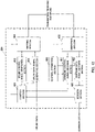
- FIG. 12 is a diagram to show a principle functional structure of the baseband signal processing section 204 provided in the user terminal 20.
- the baseband signal processing section 204 provided in the user terminal 20 is comprised at least of a control section 401, an uplink control signal generating section 402, an uplink data signal generating section 403, a mapping section 404, a demapping section 405, a channel estimation section 406, a downlink control signal decoding section 407, a downlink data signal decoding section 408 and a decision section 409.
- the control section 401 controls the generation of uplink control signals (A/N signals, etc.), uplink data signals and so on based on downlink control signals (PDCCH signals) transmitted from the radio base station 10, retransmission control decisions in response to the PDSCH signals received, and so on.
- the downlink control signals received from the radio base station are output from the downlink control signal decoding section 407, and the retransmission control decisions are output from the decision section 409.
- the control section 401 controls the allocation of the signals in D2D signal transmission/reception to D2D signal transmitting/receiving resources based on the D2D signal transmitting/receiving resources information reported from the radio base station 10.
- the control section 401 controls the synchronization of D2D signal transmitting/receiving resources based on the system information.
- the uplink control signal generating section 402 generates uplink control signals (feedback signals such as delivery acknowledgement signals, channel state information (CSI) and so on) based on commands from the control section 401.
- the uplink data signal generating section 403 generates uplink data signals based on commands from the control section 401. Note that, when a UL grant is contained in a downlink control signal reported from the radio base station, the control section 401 commands the uplink data signal generating section 403 to generate an uplink data signal.
- the mapping section 404 controls the allocation of the uplink control signals (delivery acknowledgment signals and so on) and the uplink data signals to radio resources (PUCCH, PUSCH, etc.) based on commands from the control section 401.
- the mapping section 404 controls the allocation of signals in D2D signal transmission/reception to D2D signal transmitting/receiving resources based on commands from the control section 401.
- the demapping section 405 demaps downlink signals transmitted from the radio base station 10 and separates the downlink signals.
- the channel estimation section 406 estimates channel states from the reference signals included in the received signals separated in the demapping section 406, and outputs the estimated channel states to the downlink control signal decoding section 407 and the downlink data signal decoding section 408.
- the downlink control signal decoding section 407 decodes the downlink control signals (PDCCH signals) transmitted in the downlink control channel (PDCCH), and outputs the scheduling information (information regarding the allocation to uplink resources) to the control section 401. Also, if information related to the cells for feeding back delivery acknowledgment signals and information as to whether or not RF (Radio Frequency) tuning is applied are included in downlink control signals, these pieces of information are also output to the control section 401.
- RF Radio Frequency
- the downlink data signal decoding section 408 decodes the downlink data signals transmitted in the downlink shared channel (PDSCH), and outputs the results to the decision section 409.
- the decision section 409 makes retransmission control decisions (A/N decisions) based on the decoding results in the downlink data signal decoding section 408, and outputs the results to the control section 401.
Claims (2)
- Terminal utilisateur (20) qui est configuré pour transmettre et recevoir des signaux de dispositif à dispositif, comprenant :une section de réception (203) configurée pour recevoir des informations système dans une première porteuse de fréquence, qui sont transmises à partir d'une station de base cellulaire de connexion ou de desserte (10) et qui contiennent au moins des informations concernant des ressources pour transmettre et recevoir les signaux de dispositif à dispositif ; etune section de commande (401) qui, sur la base des informations concernant les ressources de transmission/réception de signaux de dispositif à dispositif, est configurée pour exécuter une commande de sorte que les signaux de dispositif à dispositif sont transmis et reçus dans une seconde porteuse de fréquence, qui est différente de la première porteuse de fréquence,dans lequel la section de commande est configurée pour commander une synchronisation des ressources de transmission/réception de signaux de dispositif à dispositif, sur la base des informations système, caractérisé en ce quele terminal utilisateur est configuré pour, lorsqu'une première cellule et une seconde cellule fonctionnent de manière synchrone, synchroniser les ressources de transmission/réception de signaux de dispositif à dispositif à l'aide de signaux de synchronisation de la première cellule en tant que source de synchronisation, et lorsque la première cellule et la seconde cellule fonctionnent de manière asynchrone et que le terminal utilisateur détecte des signaux de synchronisation de la seconde cellule, pour synchroniser les ressources de transmission/réception de signaux de dispositif à dispositif à l'aide de signaux de synchronisation de la seconde cellule en tant que source de synchronisation,dans lequel la première cellule est une macro cellule et la seconde cellule est une petite cellule.
- Procédé de radiocommunication dans un terminal utilisateur (20) qui est apte à transmettre et recevoir des signaux de dispositif à dispositif, le procédé de radiocommunication comprenant :la réception d'informations système dans une première porteuse de fréquence, qui sont transmises à partir d'une station de base cellulaire de connexion ou de desserte (10) et qui contiennent au moins des informations concernant des ressources pour transmettre et recevoir des signaux de dispositif à dispositif ; etsur la base des informations concernant les ressources de transmission/réception de signaux de dispositif à dispositif, l'exécution d'une commande de sorte que les signaux de dispositif à dispositif sont transmis et reçus à l'aide de ressources dans une seconde porteuse de fréquence, qui est différente de la première porteuse de fréquence,dans lequella commande comprend la commande d'une synchronisation des ressources de transmission/réception de signaux de dispositif à dispositif, sur la base des informations système,caractérisé en ce quelorsqu'une première cellule et une seconde cellule fonctionnent de manière synchrone, le terminal utilisateur synchronise les ressources de transmission/réception de signaux de dispositif à dispositif à l'aide de signaux de synchronisation de la première cellule en tant que source de synchronisation, etlorsque la première cellule et la seconde cellule fonctionnent de manière asynchrone et que le terminal utilisateur détecte des signaux de synchronisation de la seconde cellule, le terminal utilisateur synchronise les ressources de transmission/réception de signaux de dispositif à dispositif à l'aide de signaux de synchronisation de la seconde cellule en tant que source de synchronisation,dans lequel la première cellule est une macro cellule et la seconde cellule est une petite cellule.
Applications Claiming Priority (2)
| Application Number | Priority Date | Filing Date | Title |
|---|---|---|---|
| JP2013269756A JP2015126393A (ja) | 2013-12-26 | 2013-12-26 | ユーザ端末、無線基地局、無線通信システムおよび無線通信方法 |
| PCT/JP2014/080073 WO2015098340A1 (fr) | 2013-12-26 | 2014-11-13 | Terminal utilisateur, dispositif de station de base sans fil, système de communication sans fil et procédé de communication sans fil |
Publications (3)
| Publication Number | Publication Date |
|---|---|
| EP3089531A1 EP3089531A1 (fr) | 2016-11-02 |
| EP3089531A4 EP3089531A4 (fr) | 2017-08-30 |
| EP3089531B1 true EP3089531B1 (fr) | 2022-05-18 |
Family
ID=53478216
Family Applications (1)
| Application Number | Title | Priority Date | Filing Date |
|---|---|---|---|
| EP14874819.7A Active EP3089531B1 (fr) | 2013-12-26 | 2014-11-13 | Terminal utilisateur et procédé de communication radio |
Country Status (6)
| Country | Link |
|---|---|
| US (1) | US10631294B2 (fr) |
| EP (1) | EP3089531B1 (fr) |
| JP (1) | JP2015126393A (fr) |
| CN (2) | CN105900508A (fr) |
| PL (1) | PL3089531T3 (fr) |
| WO (1) | WO2015098340A1 (fr) |
Families Citing this family (17)
| Publication number | Priority date | Publication date | Assignee | Title |
|---|---|---|---|---|
| WO2015198490A1 (fr) * | 2014-06-27 | 2015-12-30 | 富士通株式会社 | Système de communication, station de base et terminal de communication |
| JP2016096475A (ja) | 2014-11-14 | 2016-05-26 | Kddi株式会社 | 無線制御装置、端末装置、および通信方法 |
| US10778324B2 (en) * | 2015-06-25 | 2020-09-15 | Nec Corporation | D2D communication control apparatus, radio terminal, relay radio terminal candidate selection method, and non-transitory computer readable medium |
| JP6466621B2 (ja) * | 2015-07-09 | 2019-02-06 | エルジー エレクトロニクス インコーポレイティド | 無線通信システムにおける端末の同期化実行方法及び前記方法を利用する端末 |
| BR112018002682B1 (pt) * | 2015-08-13 | 2023-12-26 | Telecom Italia S.P.A | Método para habilitar serviços de proximidade de rede intermóveis, e, rede móvel |
| CN106454746B (zh) * | 2015-08-13 | 2020-06-26 | 华为技术有限公司 | 设备到设备通信方法、装置和系统 |
| JPWO2017026543A1 (ja) * | 2015-08-13 | 2018-05-31 | 株式会社Nttドコモ | ユーザ装置、及びd2d信号送信方法 |
| EP3338494B1 (fr) | 2015-08-21 | 2023-01-04 | Nec Corporation | Procédé et système de communication d'un véhicule tout-connecté (v2x) |
| CN107645392B (zh) | 2016-07-20 | 2020-07-10 | 电信科学技术研究院 | 一种用户设备间的通信方法及装置、通信控制方法及装置 |
| US10631173B2 (en) | 2016-09-02 | 2020-04-21 | Qualcomm Incorporated | Radio (NR) procedures for shared spectrum |
| RU2020112063A (ru) * | 2017-09-08 | 2021-10-08 | Нтт Докомо, Инк. | Пользовательский терминал и способ радиосвязи |
| WO2019084924A1 (fr) * | 2017-11-03 | 2019-05-09 | Oppo广东移动通信有限公司 | Procédé et dispositif de transmission de données |
| EP3528582B1 (fr) * | 2018-02-15 | 2023-08-16 | Comcast Cable Communications, LLC | Accès aléatoire à l'aide d'une liaison montante supplémentaire |
| US11457431B2 (en) * | 2018-08-03 | 2022-09-27 | FG Innovation Company Limited | Sidelink radio resource allocation |
| US20210314062A1 (en) * | 2018-08-09 | 2021-10-07 | Ntt Docomo, Inc. | User terminal and radio communication method |
| CN110972104B (zh) * | 2018-09-28 | 2021-07-09 | 展讯通信(上海)有限公司 | V2x通信方法及装置 |
| JP6766232B2 (ja) * | 2019-07-08 | 2020-10-07 | Kddi株式会社 | 基地局装置、端末装置、および通信方法 |
Family Cites Families (17)
| Publication number | Priority date | Publication date | Assignee | Title |
|---|---|---|---|---|
| CN102550098B (zh) * | 2009-10-07 | 2016-05-25 | 住友电气工业株式会社 | 基站装置 |
| US9363798B2 (en) * | 2011-03-11 | 2016-06-07 | Lg Electronics Inc. | Method and device for terminal to transmit/receive signal in wireless communication system having carrier aggregation technique applied thereto |
| US8705421B2 (en) * | 2011-04-22 | 2014-04-22 | Qualcomm Incorporated | Methods and apparatus for timing synchronization for peer to peer devices operating in WWAN spectrum |
| EP2716102B1 (fr) * | 2011-06-01 | 2021-01-06 | Ntt Docomo, Inc. | Accès local amélioré dans des communications mobiles à l'aide de dispositifs de petit noeud |
| CN103037359A (zh) | 2011-09-30 | 2013-04-10 | 华为技术有限公司 | 一种实现设备到设备的通讯方法、终端及系统 |
| GB2498765A (en) * | 2012-01-27 | 2013-07-31 | Renesas Mobile Corp | Discovery signalling in a device-to-device communication system |
| JP5940867B2 (ja) | 2012-04-18 | 2016-06-29 | 株式会社Nttドコモ | 無線通信システム、通信制御装置、無線通信端末及び通信制御方法 |
| JP6360277B2 (ja) | 2012-04-25 | 2018-07-18 | 株式会社Nttドコモ | 課金システム、課金装置及び課金方法 |
| US9019913B2 (en) | 2012-05-21 | 2015-04-28 | Qualcomm Incorporated | Methods and apparatus for providing D2D system information to a UE served by a home evolved Node-B |
| EP2853052A1 (fr) | 2012-05-23 | 2015-04-01 | Kyocera Corporation | Messagerie d'accusé de réception sur des signaux de référence |
| CN104350796B (zh) * | 2012-05-31 | 2018-04-10 | 富士通株式会社 | 无线通信系统、无线基站装置、终端装置以及无线资源的分配方法 |
| CN102843162B (zh) * | 2012-09-12 | 2014-11-05 | 西安交通大学 | 一种蜂窝网络中采用d2d技术的扩频通信方法 |
| EP2923472B1 (fr) * | 2012-11-23 | 2020-01-08 | Telefonaktiebolaget LM Ericsson (publ) | Procédés et appareils de gestion de ressource radio |
| CN103874205B (zh) | 2012-12-12 | 2019-01-08 | 中兴通讯股份有限公司 | 数据的传输、接收方法及装置 |
| US9042938B2 (en) * | 2012-12-27 | 2015-05-26 | Google Technology Holdings LLC | Method and apparatus for device-to-device communication |
| CN112087788B (zh) * | 2013-05-06 | 2023-07-25 | 太浩研究有限公司 | 接入网发现和选择 |
| CN103298141B (zh) * | 2013-06-09 | 2016-01-06 | 北京邮电大学 | 蜂窝与终端直通混合网络中d2d通信的载波复用方法 |
-
2013
- 2013-12-26 JP JP2013269756A patent/JP2015126393A/ja active Pending
-
2014
- 2014-11-13 US US15/107,162 patent/US10631294B2/en active Active
- 2014-11-13 WO PCT/JP2014/080073 patent/WO2015098340A1/fr active Application Filing
- 2014-11-13 CN CN201480070546.2A patent/CN105900508A/zh active Pending
- 2014-11-13 EP EP14874819.7A patent/EP3089531B1/fr active Active
- 2014-11-13 PL PL14874819.7T patent/PL3089531T3/pl unknown
- 2014-11-13 CN CN201911021515.9A patent/CN110740518B/zh active Active
Also Published As
| Publication number | Publication date |
|---|---|
| WO2015098340A1 (fr) | 2015-07-02 |
| CN105900508A (zh) | 2016-08-24 |
| US10631294B2 (en) | 2020-04-21 |
| JP2015126393A (ja) | 2015-07-06 |
| US20170034825A1 (en) | 2017-02-02 |
| PL3089531T3 (pl) | 2022-07-18 |
| EP3089531A4 (fr) | 2017-08-30 |
| CN110740518B (zh) | 2023-10-24 |
| EP3089531A1 (fr) | 2016-11-02 |
| CN110740518A (zh) | 2020-01-31 |
Similar Documents
| Publication | Publication Date | Title |
|---|---|---|
| EP3089531B1 (fr) | Terminal utilisateur et procédé de communication radio | |
| US9794968B2 (en) | Communication system, mobile terminal apparatus, local area base station and communication method | |
| US11582720B2 (en) | Vehicle-to-everything (V2X) inter-user equipment (UE) coordination | |
| JP6045808B2 (ja) | ユーザ端末、無線基地局、及び無線通信方法 | |
| US20150215847A1 (en) | Apparatus for discovery signal transmission on lte small cell | |
| EP3026965A1 (fr) | Station de base sans fil, terminal d'utilisateur, et procédé de communication sans fil | |
| WO2016112715A1 (fr) | Procédé et dispositif pour commander et gérer des ressources de cellules de desserte secondaires | |
| US10097983B2 (en) | Radio base station, user terminal and radio communication method | |
| EP3101927A1 (fr) | Terminal d'utilisateur, station de base sans fil, procédé de communications sans fil et système de communications sans fil | |
| US20240147520A1 (en) | Time-division multiplexing of uplink communications during make-before-break handover | |
| EP4272508A1 (fr) | Gestion d'interférence inter-ue de liaison latérale fr2 | |
| WO2022146544A1 (fr) | Sélection de ressources d'entraînement de faisceau par un équipement utilisateur (ue) de liaison latérale fr2 | |
| EP3065487B1 (fr) | Terminal d'utilisateur, station de base sans fil, et procédé de communication sans fil | |
| EP3029982A1 (fr) | Station de base, terminal utilisateur, et procédé de commande de communication sans fil | |
| US11723012B2 (en) | Vehicle-to-everything (V2X) destination identification sharing for inter-user equipment (UE) coordination | |
| US11540224B2 (en) | Vehicle-to-everything (V2X) inter-user equipment (UE) coordination | |
| US11831572B2 (en) | Vehicle-to-everything (V2X) inter-user equipment (UE) coordination | |
| US20230128596A1 (en) | Managing multiple simultaneous periodic uplink transmissions | |
| US20230037156A1 (en) | On demand assistance for sidelink mode 1 communication | |
| WO2023123007A1 (fr) | Réservation de surface intelligente reconfigurable (ris) pour des communications de liaison latérale |
Legal Events
| Date | Code | Title | Description |
|---|---|---|---|
| PUAI | Public reference made under article 153(3) epc to a published international application that has entered the european phase |
Free format text: ORIGINAL CODE: 0009012 |
|
| 17P | Request for examination filed |
Effective date: 20160711 |
|
| AK | Designated contracting states |
Kind code of ref document: A1 Designated state(s): AL AT BE BG CH CY CZ DE DK EE ES FI FR GB GR HR HU IE IS IT LI LT LU LV MC MK MT NL NO PL PT RO RS SE SI SK SM TR |
|
| AX | Request for extension of the european patent |
Extension state: BA ME |
|
| DAX | Request for extension of the european patent (deleted) | ||
| A4 | Supplementary search report drawn up and despatched |
Effective date: 20170801 |
|
| RIC1 | Information provided on ipc code assigned before grant |
Ipc: H04W 72/04 20090101AFI20170726BHEP Ipc: H04W 76/02 20090101ALI20170726BHEP |
|
| STAA | Information on the status of an ep patent application or granted ep patent |
Free format text: STATUS: EXAMINATION IS IN PROGRESS |
|
| 17Q | First examination report despatched |
Effective date: 20180710 |
|
| RIC1 | Information provided on ipc code assigned before grant |
Ipc: H04W 8/00 20090101ALI20200623BHEP Ipc: H04W 76/14 20180101ALI20200623BHEP Ipc: H04W 52/02 20090101ALI20200623BHEP Ipc: H04W 72/04 20090101AFI20200623BHEP |
|
| STAA | Information on the status of an ep patent application or granted ep patent |
Free format text: STATUS: EXAMINATION IS IN PROGRESS |
|
| RIC1 | Information provided on ipc code assigned before grant |
Ipc: H04W 48/12 20090101ALN20210927BHEP Ipc: H04W 76/14 20180101ALI20210927BHEP Ipc: H04W 8/00 20090101ALI20210927BHEP Ipc: H04W 52/02 20090101ALI20210927BHEP Ipc: H04W 72/04 20090101AFI20210927BHEP |
|
| GRAP | Despatch of communication of intention to grant a patent |
Free format text: ORIGINAL CODE: EPIDOSNIGR1 |
|
| STAA | Information on the status of an ep patent application or granted ep patent |
Free format text: STATUS: GRANT OF PATENT IS INTENDED |
|
| RIC1 | Information provided on ipc code assigned before grant |
Ipc: H04W 48/12 20090101ALN20211104BHEP Ipc: H04W 76/14 20180101ALI20211104BHEP Ipc: H04W 8/00 20090101ALI20211104BHEP Ipc: H04W 52/02 20090101ALI20211104BHEP Ipc: H04W 72/04 20090101AFI20211104BHEP |
|
| RIC1 | Information provided on ipc code assigned before grant |
Ipc: H04W 48/12 20090101ALN20211111BHEP Ipc: H04W 76/14 20180101ALI20211111BHEP Ipc: H04W 8/00 20090101ALI20211111BHEP Ipc: H04W 52/02 20090101ALI20211111BHEP Ipc: H04W 72/04 20090101AFI20211111BHEP |
|
| RIC1 | Information provided on ipc code assigned before grant |
Ipc: H04W 48/12 20090101ALN20211116BHEP Ipc: H04W 76/14 20180101ALI20211116BHEP Ipc: H04W 8/00 20090101ALI20211116BHEP Ipc: H04W 52/02 20090101ALI20211116BHEP Ipc: H04W 72/04 20090101AFI20211116BHEP |
|
| INTG | Intention to grant announced |
Effective date: 20211130 |
|
| RIC1 | Information provided on ipc code assigned before grant |
Ipc: H04W 48/12 20090101ALN20211122BHEP Ipc: H04W 76/14 20180101ALI20211122BHEP Ipc: H04W 8/00 20090101ALI20211122BHEP Ipc: H04W 52/02 20090101ALI20211122BHEP Ipc: H04W 72/04 20090101AFI20211122BHEP |
|
| GRAS | Grant fee paid |
Free format text: ORIGINAL CODE: EPIDOSNIGR3 |
|
| GRAA | (expected) grant |
Free format text: ORIGINAL CODE: 0009210 |
|
| STAA | Information on the status of an ep patent application or granted ep patent |
Free format text: STATUS: THE PATENT HAS BEEN GRANTED |
|
| AK | Designated contracting states |
Kind code of ref document: B1 Designated state(s): AL AT BE BG CH CY CZ DE DK EE ES FI FR GB GR HR HU IE IS IT LI LT LU LV MC MK MT NL NO PL PT RO RS SE SI SK SM TR |
|
| REG | Reference to a national code |
Ref country code: GB Ref legal event code: FG4D |
|
| REG | Reference to a national code |
Ref country code: CH Ref legal event code: EP |
|
| REG | Reference to a national code |
Ref country code: IE Ref legal event code: FG4D |
|
| REG | Reference to a national code |
Ref country code: DE Ref legal event code: R096 Ref document number: 602014083805 Country of ref document: DE |
|
| REG | Reference to a national code |
Ref country code: AT Ref legal event code: REF Ref document number: 1493862 Country of ref document: AT Kind code of ref document: T Effective date: 20220615 |
|
| REG | Reference to a national code |
Ref country code: LT Ref legal event code: MG9D |
|
| REG | Reference to a national code |
Ref country code: NL Ref legal event code: MP Effective date: 20220518 |
|
| REG | Reference to a national code |
Ref country code: AT Ref legal event code: MK05 Ref document number: 1493862 Country of ref document: AT Kind code of ref document: T Effective date: 20220518 |
|
| PG25 | Lapsed in a contracting state [announced via postgrant information from national office to epo] |
Ref country code: SE Free format text: LAPSE BECAUSE OF FAILURE TO SUBMIT A TRANSLATION OF THE DESCRIPTION OR TO PAY THE FEE WITHIN THE PRESCRIBED TIME-LIMIT Effective date: 20220518 Ref country code: PT Free format text: LAPSE BECAUSE OF FAILURE TO SUBMIT A TRANSLATION OF THE DESCRIPTION OR TO PAY THE FEE WITHIN THE PRESCRIBED TIME-LIMIT Effective date: 20220919 Ref country code: NO Free format text: LAPSE BECAUSE OF FAILURE TO SUBMIT A TRANSLATION OF THE DESCRIPTION OR TO PAY THE FEE WITHIN THE PRESCRIBED TIME-LIMIT Effective date: 20220818 Ref country code: NL Free format text: LAPSE BECAUSE OF FAILURE TO SUBMIT A TRANSLATION OF THE DESCRIPTION OR TO PAY THE FEE WITHIN THE PRESCRIBED TIME-LIMIT Effective date: 20220518 Ref country code: LT Free format text: LAPSE BECAUSE OF FAILURE TO SUBMIT A TRANSLATION OF THE DESCRIPTION OR TO PAY THE FEE WITHIN THE PRESCRIBED TIME-LIMIT Effective date: 20220518 Ref country code: HR Free format text: LAPSE BECAUSE OF FAILURE TO SUBMIT A TRANSLATION OF THE DESCRIPTION OR TO PAY THE FEE WITHIN THE PRESCRIBED TIME-LIMIT Effective date: 20220518 Ref country code: GR Free format text: LAPSE BECAUSE OF FAILURE TO SUBMIT A TRANSLATION OF THE DESCRIPTION OR TO PAY THE FEE WITHIN THE PRESCRIBED TIME-LIMIT Effective date: 20220819 Ref country code: FI Free format text: LAPSE BECAUSE OF FAILURE TO SUBMIT A TRANSLATION OF THE DESCRIPTION OR TO PAY THE FEE WITHIN THE PRESCRIBED TIME-LIMIT Effective date: 20220518 Ref country code: ES Free format text: LAPSE BECAUSE OF FAILURE TO SUBMIT A TRANSLATION OF THE DESCRIPTION OR TO PAY THE FEE WITHIN THE PRESCRIBED TIME-LIMIT Effective date: 20220518 Ref country code: BG Free format text: LAPSE BECAUSE OF FAILURE TO SUBMIT A TRANSLATION OF THE DESCRIPTION OR TO PAY THE FEE WITHIN THE PRESCRIBED TIME-LIMIT Effective date: 20220818 Ref country code: AT Free format text: LAPSE BECAUSE OF FAILURE TO SUBMIT A TRANSLATION OF THE DESCRIPTION OR TO PAY THE FEE WITHIN THE PRESCRIBED TIME-LIMIT Effective date: 20220518 |
|
| PG25 | Lapsed in a contracting state [announced via postgrant information from national office to epo] |
Ref country code: RS Free format text: LAPSE BECAUSE OF FAILURE TO SUBMIT A TRANSLATION OF THE DESCRIPTION OR TO PAY THE FEE WITHIN THE PRESCRIBED TIME-LIMIT Effective date: 20220518 Ref country code: LV Free format text: LAPSE BECAUSE OF FAILURE TO SUBMIT A TRANSLATION OF THE DESCRIPTION OR TO PAY THE FEE WITHIN THE PRESCRIBED TIME-LIMIT Effective date: 20220518 Ref country code: IS Free format text: LAPSE BECAUSE OF FAILURE TO SUBMIT A TRANSLATION OF THE DESCRIPTION OR TO PAY THE FEE WITHIN THE PRESCRIBED TIME-LIMIT Effective date: 20220918 |
|
| PG25 | Lapsed in a contracting state [announced via postgrant information from national office to epo] |
Ref country code: SM Free format text: LAPSE BECAUSE OF FAILURE TO SUBMIT A TRANSLATION OF THE DESCRIPTION OR TO PAY THE FEE WITHIN THE PRESCRIBED TIME-LIMIT Effective date: 20220518 Ref country code: SK Free format text: LAPSE BECAUSE OF FAILURE TO SUBMIT A TRANSLATION OF THE DESCRIPTION OR TO PAY THE FEE WITHIN THE PRESCRIBED TIME-LIMIT Effective date: 20220518 Ref country code: RO Free format text: LAPSE BECAUSE OF FAILURE TO SUBMIT A TRANSLATION OF THE DESCRIPTION OR TO PAY THE FEE WITHIN THE PRESCRIBED TIME-LIMIT Effective date: 20220518 Ref country code: EE Free format text: LAPSE BECAUSE OF FAILURE TO SUBMIT A TRANSLATION OF THE DESCRIPTION OR TO PAY THE FEE WITHIN THE PRESCRIBED TIME-LIMIT Effective date: 20220518 Ref country code: DK Free format text: LAPSE BECAUSE OF FAILURE TO SUBMIT A TRANSLATION OF THE DESCRIPTION OR TO PAY THE FEE WITHIN THE PRESCRIBED TIME-LIMIT Effective date: 20220518 Ref country code: CZ Free format text: LAPSE BECAUSE OF FAILURE TO SUBMIT A TRANSLATION OF THE DESCRIPTION OR TO PAY THE FEE WITHIN THE PRESCRIBED TIME-LIMIT Effective date: 20220518 |
|
| REG | Reference to a national code |
Ref country code: DE Ref legal event code: R097 Ref document number: 602014083805 Country of ref document: DE |
|
| PLBE | No opposition filed within time limit |
Free format text: ORIGINAL CODE: 0009261 |
|
| STAA | Information on the status of an ep patent application or granted ep patent |
Free format text: STATUS: NO OPPOSITION FILED WITHIN TIME LIMIT |
|
| PG25 | Lapsed in a contracting state [announced via postgrant information from national office to epo] |
Ref country code: AL Free format text: LAPSE BECAUSE OF FAILURE TO SUBMIT A TRANSLATION OF THE DESCRIPTION OR TO PAY THE FEE WITHIN THE PRESCRIBED TIME-LIMIT Effective date: 20220518 |
|
| 26N | No opposition filed |
Effective date: 20230221 |
|
| PG25 | Lapsed in a contracting state [announced via postgrant information from national office to epo] |
Ref country code: SI Free format text: LAPSE BECAUSE OF FAILURE TO SUBMIT A TRANSLATION OF THE DESCRIPTION OR TO PAY THE FEE WITHIN THE PRESCRIBED TIME-LIMIT Effective date: 20220518 |
|
| P01 | Opt-out of the competence of the unified patent court (upc) registered |
Effective date: 20230509 |
|
| PG25 | Lapsed in a contracting state [announced via postgrant information from national office to epo] |
Ref country code: MC Free format text: LAPSE BECAUSE OF FAILURE TO SUBMIT A TRANSLATION OF THE DESCRIPTION OR TO PAY THE FEE WITHIN THE PRESCRIBED TIME-LIMIT Effective date: 20220518 |
|
| REG | Reference to a national code |
Ref country code: CH Ref legal event code: PL |
|
| REG | Reference to a national code |
Ref country code: BE Ref legal event code: MM Effective date: 20221130 |
|
| PG25 | Lapsed in a contracting state [announced via postgrant information from national office to epo] |
Ref country code: LI Free format text: LAPSE BECAUSE OF NON-PAYMENT OF DUE FEES Effective date: 20221130 Ref country code: CH Free format text: LAPSE BECAUSE OF NON-PAYMENT OF DUE FEES Effective date: 20221130 |
|
| PG25 | Lapsed in a contracting state [announced via postgrant information from national office to epo] |
Ref country code: LU Free format text: LAPSE BECAUSE OF NON-PAYMENT OF DUE FEES Effective date: 20221113 |
|
| PG25 | Lapsed in a contracting state [announced via postgrant information from national office to epo] |
Ref country code: IE Free format text: LAPSE BECAUSE OF NON-PAYMENT OF DUE FEES Effective date: 20221113 |
|
| PG25 | Lapsed in a contracting state [announced via postgrant information from national office to epo] |
Ref country code: FR Free format text: LAPSE BECAUSE OF NON-PAYMENT OF DUE FEES Effective date: 20221130 Ref country code: BE Free format text: LAPSE BECAUSE OF NON-PAYMENT OF DUE FEES Effective date: 20221130 |
|
| PGFP | Annual fee paid to national office [announced via postgrant information from national office to epo] |
Ref country code: GB Payment date: 20231123 Year of fee payment: 10 |
|
| PGFP | Annual fee paid to national office [announced via postgrant information from national office to epo] |
Ref country code: IT Payment date: 20231124 Year of fee payment: 10 Ref country code: DE Payment date: 20231121 Year of fee payment: 10 |
|
| PGFP | Annual fee paid to national office [announced via postgrant information from national office to epo] |
Ref country code: PL Payment date: 20231103 Year of fee payment: 10 |
|
| PG25 | Lapsed in a contracting state [announced via postgrant information from national office to epo] |
Ref country code: HU Free format text: LAPSE BECAUSE OF FAILURE TO SUBMIT A TRANSLATION OF THE DESCRIPTION OR TO PAY THE FEE WITHIN THE PRESCRIBED TIME-LIMIT; INVALID AB INITIO Effective date: 20141113 |
|
| PG25 | Lapsed in a contracting state [announced via postgrant information from national office to epo] |
Ref country code: CY Free format text: LAPSE BECAUSE OF FAILURE TO SUBMIT A TRANSLATION OF THE DESCRIPTION OR TO PAY THE FEE WITHIN THE PRESCRIBED TIME-LIMIT Effective date: 20220511 |