EP3089325A1 - Rotor and motor having the same - Google Patents
Rotor and motor having the same Download PDFInfo
- Publication number
- EP3089325A1 EP3089325A1 EP16165200.3A EP16165200A EP3089325A1 EP 3089325 A1 EP3089325 A1 EP 3089325A1 EP 16165200 A EP16165200 A EP 16165200A EP 3089325 A1 EP3089325 A1 EP 3089325A1
- Authority
- EP
- European Patent Office
- Prior art keywords
- rotor
- protrusion
- rotor body
- height
- slide
- Prior art date
- Legal status (The legal status is an assumption and is not a legal conclusion. Google has not performed a legal analysis and makes no representation as to the accuracy of the status listed.)
- Granted
Links
Images





Classifications
-
- H—ELECTRICITY
- H02—GENERATION; CONVERSION OR DISTRIBUTION OF ELECTRIC POWER
- H02K—DYNAMO-ELECTRIC MACHINES
- H02K16/00—Machines with more than one rotor or stator
- H02K16/02—Machines with one stator and two or more rotors
-
- H—ELECTRICITY
- H02—GENERATION; CONVERSION OR DISTRIBUTION OF ELECTRIC POWER
- H02K—DYNAMO-ELECTRIC MACHINES
- H02K1/00—Details of the magnetic circuit
- H02K1/06—Details of the magnetic circuit characterised by the shape, form or construction
- H02K1/22—Rotating parts of the magnetic circuit
- H02K1/24—Rotor cores with salient poles ; Variable reluctance rotors
-
- H—ELECTRICITY
- H02—GENERATION; CONVERSION OR DISTRIBUTION OF ELECTRIC POWER
- H02K—DYNAMO-ELECTRIC MACHINES
- H02K1/00—Details of the magnetic circuit
- H02K1/06—Details of the magnetic circuit characterised by the shape, form or construction
- H02K1/22—Rotating parts of the magnetic circuit
- H02K1/24—Rotor cores with salient poles ; Variable reluctance rotors
- H02K1/243—Rotor cores with salient poles ; Variable reluctance rotors of the claw-pole type
-
- H—ELECTRICITY
- H02—GENERATION; CONVERSION OR DISTRIBUTION OF ELECTRIC POWER
- H02K—DYNAMO-ELECTRIC MACHINES
- H02K19/00—Synchronous motors or generators
- H02K19/02—Synchronous motors
-
- H—ELECTRICITY
- H02—GENERATION; CONVERSION OR DISTRIBUTION OF ELECTRIC POWER
- H02K—DYNAMO-ELECTRIC MACHINES
- H02K3/00—Details of windings
- H02K3/04—Windings characterised by the conductor shape, form or construction, e.g. with bar conductors
- H02K3/18—Windings for salient poles
-
- H—ELECTRICITY
- H02—GENERATION; CONVERSION OR DISTRIBUTION OF ELECTRIC POWER
- H02K—DYNAMO-ELECTRIC MACHINES
- H02K2213/00—Specific aspects, not otherwise provided for and not covered by codes H02K2201/00 - H02K2211/00
- H02K2213/03—Machines characterised by numerical values, ranges, mathematical expressions or similar information
-
- H—ELECTRICITY
- H02—GENERATION; CONVERSION OR DISTRIBUTION OF ELECTRIC POWER
- H02K—DYNAMO-ELECTRIC MACHINES
- H02K2213/00—Specific aspects, not otherwise provided for and not covered by codes H02K2201/00 - H02K2211/00
- H02K2213/12—Machines characterised by the modularity of some components
Definitions
- the present invention relates to a rotor and a motor having the same, and more particularly, to a rotor around which a coil is wound and a motor having the same.
- a vehicle includes a starter motor which drives an engine and an alternator which generates electricity using a rotational force of the engine.
- the starter motor has an ignition switch is connected to a power supply of a battery by an operation of a driver when the vehicle is started up, then the power is supplied to the starter motor, the engine is rotated by a driving force generated by the starter motor, and thus the vehicle is started up.
- the alternator is connected to a driving unit of the engine to rotate the rotor while a magnetic field is formed by a driving force of the engine, then an alternating current (AC) power is generated, and thus the battery is charged using a rectifier or the like.
- AC alternating current
- both of the starter motor and the alternator are configured in a stator-rotor structure, the structures of the starter motor and the alternator are very similar to each other, and can be operated as a power generator or a motor depending on whether a force or power is applied.
- BSG belt driven starter generator
- a wound rotor synchronous motor is a motor having a protrusion which protrudes from an outer circumferential surface of a rotor core and around which a coil is wound.
- the wound rotor synchronous motor has not only been mainly used as a generator but also been recently proposed as a form of a traction motor since a development of a rare earth-free motor has been spotlighted.
- the motor has to increase the number of coils or a current to increase torque.
- an increase in torque of the motor is limited because there is a limit in increasing the number of winding coils due to spatial constraints and in increasing a current due to a current limit.
- the present invention is directed to a rotor capable of increasing torque by increasing a space factor of a coil and facilitating assembly, and a motor having the same.
- a rotor including a first rotor body including a first protrusion protruding from an outer circumferential surface thereof and a second rotor body stacked on and coupled to the first rotor body and including a second protrusion disposed at a position different from a position of the first protrusion with respect to a circumferential direction and protruding from an outer circumferential surface thereof, wherein a height of the first protrusion is formed to be greater than a height of the first rotor body, and a height of the second protrusion is formed to be greater than a height of the second rotor body.
- the first protrusion may include a first extension protruding further than a lower surface of the first rotor body
- the second protrusion may include a second extension protruding further than an upper surface of the second rotor body.
- Each of the first extension and the second extension may include a slide edge part formed at an inner end thereof.
- the slide edge part may include a slide protrusion protruding and disposed in a height direction
- the first rotor body and the second rotor body may include slide grooves concavely formed on the outer circumferential surfaces thereof and disposed in the height direction, respectively.
- the slide edge part may include a slide groove protruding and disposed in a height direction
- the first rotor body and the second rotor body may include slide grooves concavely formed on the outer circumferential surfaces thereof and disposed in the height direction, respectively.
- the slide protrusion or the slide groove may be disposed in the center of the slide edge parts with respect to the circumferential direction.
- the slide protrusion may have a width reduced from an inner side toward an outer side, and the slide groove may have a width increased from an inner side toward an outer side.
- the slide edge part of the first rotor body may have an inner circumferential surface corresponding to the outer circumferential surface of the second rotor body, and the slide edge part of the second rotor body may have an inner circumferential surface corresponding to the outer circumferential surface of the first rotor body.
- the slide protrusion or the slide groove may be formed on the inner circumferential surface of the slide edge part.
- a motor which includes a stator, a rotor including a first rotor body disposed in the stator and including a first protrusion protruding from an outer circumferential surface thereof and a second rotor body stacked on and coupled to the first rotor body and including a second protrusion disposed at a position different from a position of the first protrusion with respect to a circumferential direction and protruding from an outer circumferential surface thereof, wherein a height of the first protrusion is formed to be greater than a height of the first rotor body, and a height of the second protrusion is formed to be greater than a height of the second rotor body, a coil unit wound around each of the first protrusion and the second protrusion, and a rotating shaft coupled to the rotor.
- a rotor including a first rotor body including a first protrusion protruding from an outer circumferential surface thereof, a second rotor body downwardly stacked on and coupled to the first rotor body and including a second protrusion disposed at a position different from a position of the first protrusion with respect to a circumferential direction and protruding from an outer circumferential surface thereof, and a third rotor body upwardly stacked on and coupled to the first rotor body and including a third protrusion disposed at a position different from the position of the first protrusion and the position of the second protrusion with respect to the circumferential direction and protruding from an outer circumferential surface thereof, wherein a height of the first protrusion is formed to be greater than a height of the first rotor body, a height of the second protrusion is formed to be greater than a height of the second rotor body, and a height of the third protrutru
- the first protrusion may include a first extension protruding further than a lower surface of the first rotor body
- the second protrusion may include a second extension protruding further than an upper surface and a lower surface of the second rotor body
- the third protrusion may include a third extension protruding further than an upper surface of the third rotor body.
- the first extension, the second extension, and the third extension may include a slide edge part formed on inner ends thereof.
- a motor which includes a stator, a rotor including a first rotor body disposed in the stator and including a first protrusion protruding from an outer circumferential surface thereof, a second rotor body downwardly stacked on and coupled the first rotor body and including a second protrusion disposed at a position different from a position of the first protrusion with respect to a circumferential direction and protruding from an outer circumferential surface thereof, and a third rotor body upwardly stacked on and coupled to the first rotor body and including a third protrusion disposed at a position different from the position of the first protrusion and the position of the second protrusion with respect to the circumferential direction and protruding from an outer circumferential surface thereof, wherein a height of the first protrusion is formed to be greater than a height of the first rotor body, a height of the second protrusion is formed to be greater than a height of
- first means “first,” “second,” etc.
- these elements are not to be limited by these terms. These terms are only used to distinguish one element from another. For example, a first element could be termed a second element, and similarly, a second element could be termed a first element, without departing from the scope of the present invention.
- the term “and/or” includes any and all combinations of one or more of the associated listed items.
- FIG. 1 is a view illustrating a motor according to an exemplary embodiment of the present invention.
- a motor may include a stator 30 in a housing 1.
- a rotor 10 is included in the stator 30, and a coil 40 may be wound around the rotor 10.
- the coil 40 may induce an electrical interaction with the stator 30 to rotate the rotor 10 or induce power by the rotating rotor 10.
- the motor when the motor operates as a starter motor, the rotor 10 is rotated by an applied driving current to rotate a pulley belt (not shown) connected to a rotating shaft 50 of the rotor 10, and an external component (an engine and the like) may be operated.
- a pulley belt not shown
- an external component an engine and the like
- the pulley belt (not shown) is rotated by an operation of an engine to rotate the rotor 10, and an alternating current (AC) is generated.
- the generated AC may be supplied to an external component (a battery and the like) by being converted into a direct current (DC).
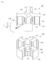
- FIG. 2 is a view illustrating the rotor shown in FIG. 1
- FIG. 3 is a view illustrating a first rotor body and a second rotor body.
- FIGS. 2 and 3 clearly illustrate only main characteristic portions for conceptually and clearly understanding the present invention. As a result, various modifications of the illustration are expected, and it is not necessary that the scope of the present invention be limited to specific shapes illustrated in the drawing.
- the rotor 10 may include a first rotor body 100 and a second rotor body 200.
- the first rotor body 100 and the second rotor body 200 are elements which form the rotor by being mutually stacked in a height direction.
- Each of the first rotor body 100 and the second rotor body 200 may be formed by stacking a plurality of plates.
- the first rotor body 100 is illustrated as being downwardly coupled to the second rotor body 200.
- the first rotor body 100 may include first protrusions 110.
- the first protrusions 110 protrude from an outer circumferential surface of the first rotor body 100 in a radial direction. Coils are wound around the first protrusions 110, and insulators may be installed on the first protrusions 110 for insulation.
- the first protrusions 110 may be disposed in a circumferential direction of a boss 120 in a cylindrical shape at regular intervals.
- a hole 130 into which the rotating shaft 50 is inserted may be formed in the center of the boss 120.
- the first protrusion 110 may include an arm-type body 111 connected to the boss 120 and a rim-type blocking protrusion 112 formed at a front end of the arm-type body 111. A coil is wound around the arm-type body 111. As shown in FIG. 3 , all four of the first protrusions 110 may be disposed at regular intervals. The number of the first protrusions 110 may vary depending on the number of poles of the motor.
- the second rotor body 200 may include second protrusions 210.
- the second protrusions 210 protrude from an outer circumferential surface of the second rotor body 200 in a radial direction. Coils are wound around the second protrusions 210, and insulators may also be installed on the second protrusions 210 for insulation. Further, the second protrusions 210 may be disposed in a circumferential direction of a boss 220 in a cylindrical shape at regular intervals. A hole 230 into which the rotating shaft 50 is inserted may be formed in the center of the boss 220.
- the second protrusions 210 have the same shape as the shape of the first protrusion 110.
- the second protrusion 210 may include an arm-type body 211 connected to the boss 220 and a rim-type blocking protrusion 212 formed at a front end of the arm-type body 211. As shown in FIG. 3 , all four of the second protrusions 210 may be disposed at regular intervals. The number of the second protrusions 210 may vary depending on the number of poles of the motor.
- the first rotor body 100 and the second rotor body 200 are disposed so that the first rotor body 100 is disposed at a higher level than the second rotor body 200 and the second rotor body 200 is disposed at a lower level than the first rotor body 100 with respect to an axial center, and thus the respective protrusions 110 and 210 may be stacked and coupled to each other in a complementary state.
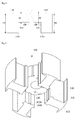
- FIG. 4 is a view illustrating a first extension
- FIG. 5 is a view illustrating the bottom of the first extension.
- a height h2 of the first protrusion 110 is formed to be greater than a height h1 of the cylindrical boss 120, that is, a height of a body of the first rotor body 100.
- the height is based on an axial direction of the motor.
- the first protrusion 110 may include a first extension 113 protruding further downward than the boss 120.
- the first extension 113 is a portion from which the first protrusion 110 extends and to which the boss 220 of the second protrusion 210 is coupled.
- the first extension 113 may include a slide edge part 113a having a curved inner circumferential surface aligned with an outer circumferential surface of the cylindrical boss 220 of the second rotor body 200.
- the inner circumferential surface of the slide edge part 113a slidably comes in contact with the outer circumferential surface of the boss 220 of the second protrusion 210.
- a slide protrusion 113b may be formed from the inner circumferential surface of the slide edge part 113a in an axial direction.
- the slide protrusion 113b is inserted into a slide groove 221 formed in the cylindrical boss 220 of the second rotor body 200 to allow the first rotor body 100 and the second rotor body 200 to be coupled to each other.
- a slide groove 121 may be formed in an outer circumferential surface of the boss 120 of the first extension 113 in the axial direction.
- FIG. 6 is a view illustrating the second extension.
- a height h4 of the second protrusion 210 is formed to be greater than a height h3 of the cylindrical boss 220, that is, the height of a body of the second rotor body 200.
- the second protrusion 210 may include a second extension 213 protruding further upward than the boss 220.
- the second extension 213 is a portion from which the second protrusion 210 extends and to which the boss 120 of the first protrusion 110 is coupled.
- the second extension 213 may include a slide edge part 213a having a curved inner circumferential surface aligned with the outer circumferential surface of the cylindrical boss 120 of the first rotor body 100.
- the inner circumferential surface of the slide edge part 213a slidably comes in contact with the outer circumferential surface of the boss 120 of the second protrusion 110.
- a slide protrusion 213b may be formed from the inner circumferential surface of the slide edge part 213a in an axial direction.
- the slide protrusion 213b is inserted into the slide groove 121 formed in the cylindrical boss 120 of the first rotor body 100 to allow the first rotor body 100 and the second rotor body 200 to be coupled to each other.
- the slide groove 221 may be formed in the outer circumferential surface of the boss 220 of the second extension 213 in the axial direction.
- FIG. 7 is a view illustrating the rotor in which the first rotor body and the second rotor body are coupled to each other.
- the first rotor body 100 and the second rotor body 200 are coupled to form the rotor 10 so that the first protrusions 110 and the second protrusions 210 are alternately disposed with respect to a circumferential direction.
- the first protrusions 110 and the second protrusions 210 may be alternately disposed in the circumferential direction when the first rotor body 100 and the second rotor body 200 are coupled to each other.
- the slide protrusion 213b of the second protrusion 210 may be formed to correspond to a reference line H passing through the center of a width direction of the slide edge part 213a in the radial direction.
- the slide protrusion 113b of the first protrusion 110 may be also formed to correspond to a reference line passing through the center of a width direction of the slide edge part 113a in the radial direction.
- the slide protrusion 213b is formed so that a width thereof is reduced from a tip end portion to a root portion, and may be formed so that a mutual binding force is generated between the first rotor body 100 and the second rotor body 200 with respect to the radial direction.
- FIG. 8 is a view illustrating a state in which coils are wound around each of the first rotor body and the second rotor body.
- coils 40 are wound around each of the first rotor body 100 and the second rotor body 200 and then coupled to each other. Because gaps between the protrusions around which the coils are wound are wide in comparison to having a single rotor body, a coil space factor may be remarkably increased. Also, a task of winding the coils may be more easily performed.
- FIG. 9 is a view illustrating a rotor according to another embodiment
- FIG. 10 is an exploded view of the rotor shown in FIG. 9 .
- a rotor 10 may include three rotor bodies 300, 400, and 500.
- Two protrusions 310, two protrusions 410, and two protrusions 510 may be formed at the rotor bodies 300, 400, and 500, respectively.
- the three rotor bodies 300, 400, and 500 may be stacked and coupled to each other to have the same axis so that the respective protrusions 310,410 and 510 are alternately disposed with respect to a circumferential direction.
- the respective protrusions 310,410 and 510 which have the same functions and structures as those of the above-described protrusions 110 and 210, are portions around which coils are wound.
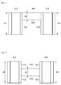
- FIG. 11 is a view illustrating a first rotor body of the rotor shown in FIG. 9
- FIG. 12 is a view illustrating a second rotor body of the rotor shown in FIG. 9
- FIG. 13 is a view illustrating a third rotor body of the rotor shown in FIG. 9 .
- a first rotor body 300 refers to a rotor body disposed as the top of the three rotor bodies.
- a height h6 of the first protrusion 310 of the first rotor body 300 is formed to be greater than a height h5 of a boss 320.
- the first protrusion 310 may be downwardly long so that a first extension 313 may come in contact with an outer circumferential surface of a boss 420 of the second rotor body 400 and an outer circumferential surface of a boss 520 of the third rotor body 500, which are disposed under the first rotor body 300.
- the height h6 of the first protrusion 310 may be formed to correspond to the entire height of the rotor 10.
- the second rotor body 400 refers to a rotor body disposed in the middle of the three rotor bodies.
- a height h8 of the second protrusion 410 of the second rotor body 400 is formed to be greater than a height h7 of the boss 420.
- the second protrusion 410 may be downwardly and upwardly long so that a second extension 413 may come in contact with an outer circumferential surface of the boss 320 of the first rotor body 300 in an upward direction and come contact with the outer circumferential surface of the boss 520 of the third rotor body 500 in a downward direction.
- the height h8 of the protrusion 410 may be formed to correspond to the entire height of the rotor 10.
- the third rotor body 500 refers to a rotor body disposed as the bottom of the three rotor bodies.
- a height h10 of the third protrusion 510 of the third rotor body 500 is formed to be greater than a height h9 of the boss 520.
- the third protrusion 510 may be upwardly long so that a third extension 513 may come in contact with the outer circumferential surface of the boss 420 of the second rotor body 400 and come contact with the outer circumferential surface of the boss 320 of the first rotor body 300, which are disposed above the third rotor body 500.
- the height h10 of the third protrusion 510 may be formed to correspond to the entire height of the rotor 10.
- the respective heights h5, h7 and h9 of the bosses 320, 420 and 520 of the rotor bodies 300, 400 and 500 may be formed to be the same.
- a plurality of rotor bodies are stacked up to form a rotor, the rotor bodies include protrusions wound which coils are wound, respectively, and the protrusions of the rotor bodies are alternately disposed with respect to a circumferential direction so that the protrusions that are divided constitute the whole protrusion. Therefore, the rotor is formed so that the coils are wound around the respective protrusions that are divided and have relatively wide winding spaces unlike a rotor integrated with protrusions around which coils are wound, thereby increasing a coil space factor and providing an effect of facilitating a winding task.
Landscapes
- Engineering & Computer Science (AREA)
- Power Engineering (AREA)
- Iron Core Of Rotating Electric Machines (AREA)
Abstract
Description
- This application claims priority to and the benefit of Korean Patent Application No.
2015-0061433, filed on April 30, 2015 - The present invention relates to a rotor and a motor having the same, and more particularly, to a rotor around which a coil is wound and a motor having the same.
- Generally, a vehicle includes a starter motor which drives an engine and an alternator which generates electricity using a rotational force of the engine. The starter motor has an ignition switch is connected to a power supply of a battery by an operation of a driver when the vehicle is started up, then the power is supplied to the starter motor, the engine is rotated by a driving force generated by the starter motor, and thus the vehicle is started up.
- In comparison, the alternator is connected to a driving unit of the engine to rotate the rotor while a magnetic field is formed by a driving force of the engine, then an alternating current (AC) power is generated, and thus the battery is charged using a rectifier or the like.
- Since both of the starter motor and the alternator are configured in a stator-rotor structure, the structures of the starter motor and the alternator are very similar to each other, and can be operated as a power generator or a motor depending on whether a force or power is applied.
- Recently, a belt driven starter generator (BSG) capable of functioning as a starter motor and an alternator with a single structure is actively being studied.
- Meanwhile, a wound rotor synchronous motor is a motor having a protrusion which protrudes from an outer circumferential surface of a rotor core and around which a coil is wound. The wound rotor synchronous motor has not only been mainly used as a generator but also been recently proposed as a form of a traction motor since a development of a rare earth-free motor has been spotlighted.
- However, the motor has to increase the number of coils or a current to increase torque. However, in the case of the BSG, there is a problem in that an increase in torque of the motor is limited because there is a limit in increasing the number of winding coils due to spatial constraints and in increasing a current due to a current limit.
- The present invention is directed to a rotor capable of increasing torque by increasing a space factor of a coil and facilitating assembly, and a motor having the same.
- An objective of the present invention is not limited to the above-mentioned objective, and other objectives of the present invention will be clearly understood by one skilled in the art from the following description.
- According to an aspect of the present invention, there is provided a rotor including a first rotor body including a first protrusion protruding from an outer circumferential surface thereof and a second rotor body stacked on and coupled to the first rotor body and including a second protrusion disposed at a position different from a position of the first protrusion with respect to a circumferential direction and protruding from an outer circumferential surface thereof, wherein a height of the first protrusion is formed to be greater than a height of the first rotor body, and a height of the second protrusion is formed to be greater than a height of the second rotor body.
- The first protrusion may include a first extension protruding further than a lower surface of the first rotor body, and the second protrusion may include a second extension protruding further than an upper surface of the second rotor body.
- Each of the first extension and the second extension may include a slide edge part formed at an inner end thereof.
- The slide edge part may include a slide protrusion protruding and disposed in a height direction, and the first rotor body and the second rotor body may include slide grooves concavely formed on the outer circumferential surfaces thereof and disposed in the height direction, respectively.
- The slide edge part may include a slide groove protruding and disposed in a height direction, and the first rotor body and the second rotor body may include slide grooves concavely formed on the outer circumferential surfaces thereof and disposed in the height direction, respectively.
- The slide protrusion or the slide groove may be disposed in the center of the slide edge parts with respect to the circumferential direction.
- The slide protrusion may have a width reduced from an inner side toward an outer side, and the slide groove may have a width increased from an inner side toward an outer side.
- The slide edge part of the first rotor body may have an inner circumferential surface corresponding to the outer circumferential surface of the second rotor body, and the slide edge part of the second rotor body may have an inner circumferential surface corresponding to the outer circumferential surface of the first rotor body.
- The slide protrusion or the slide groove may be formed on the inner circumferential surface of the slide edge part.
- According to another aspect of the present invention, there is provided a motor which includes a stator, a rotor including a first rotor body disposed in the stator and including a first protrusion protruding from an outer circumferential surface thereof and a second rotor body stacked on and coupled to the first rotor body and including a second protrusion disposed at a position different from a position of the first protrusion with respect to a circumferential direction and protruding from an outer circumferential surface thereof, wherein a height of the first protrusion is formed to be greater than a height of the first rotor body, and a height of the second protrusion is formed to be greater than a height of the second rotor body, a coil unit wound around each of the first protrusion and the second protrusion, and a rotating shaft coupled to the rotor.
- According to still another aspect of the present invention, there is provided a rotor including a first rotor body including a first protrusion protruding from an outer circumferential surface thereof, a second rotor body downwardly stacked on and coupled to the first rotor body and including a second protrusion disposed at a position different from a position of the first protrusion with respect to a circumferential direction and protruding from an outer circumferential surface thereof, and a third rotor body upwardly stacked on and coupled to the first rotor body and including a third protrusion disposed at a position different from the position of the first protrusion and the position of the second protrusion with respect to the circumferential direction and protruding from an outer circumferential surface thereof, wherein a height of the first protrusion is formed to be greater than a height of the first rotor body, a height of the second protrusion is formed to be greater than a height of the second rotor body, and a height of the third protrusion is formed to be greater than a height of the third rotor body.
- The first protrusion may include a first extension protruding further than a lower surface of the first rotor body, the second protrusion may include a second extension protruding further than an upper surface and a lower surface of the second rotor body, and the third protrusion may include a third extension protruding further than an upper surface of the third rotor body.
- The first extension, the second extension, and the third extension may include a slide edge part formed on inner ends thereof.
- According to still another aspect of the present invention, there is provided a motor which includes a stator, a rotor including a first rotor body disposed in the stator and including a first protrusion protruding from an outer circumferential surface thereof, a second rotor body downwardly stacked on and coupled the first rotor body and including a second protrusion disposed at a position different from a position of the first protrusion with respect to a circumferential direction and protruding from an outer circumferential surface thereof, and a third rotor body upwardly stacked on and coupled to the first rotor body and including a third protrusion disposed at a position different from the position of the first protrusion and the position of the second protrusion with respect to the circumferential direction and protruding from an outer circumferential surface thereof, wherein a height of the first protrusion is formed to be greater than a height of the first rotor body, a height of the second protrusion is formed to be greater than a height of the second rotor body, and a height of the third protrusion is formed to be greater than a height of the third rotor body, a coil unit wound around each of the first protrusion, the second protrusion, and the third protrusion, and a rotating shaft coupled to the rotor.
- The above and other objects, features and advantages of the present invention will become more apparent to those of ordinary skill in the art by describing exemplary embodiments thereof in detail with reference to the accompanying drawings, in which:
-
FIG. 1 is a view illustrating a motor according to an exemplarily embodiment of the present invention; -
FIG. 2 is a view illustrating a rotor shown inFIG. 1 ; -
FIG. 3 is a view illustrating a first rotor body and a second rotor body; -
FIG. 4 is a view illustrating a first extension; -
FIG. 5 is a bottom view of the first extension; -
FIG. 6 is a view illustrating a second extension; -
FIG. 7 is a view illustrating a rotor in which the first rotor body and the second rotor body are coupled to each other; -
FIG. 8 is a view illustrating a state in which a coil is wound around each of the first rotor body and the second rotor body; -
FIG. 9 is a view illustrating a rotor according to another embodiment; -
FIG. 10 is an exploded view of the rotor shown inFIG. 9 ; -
FIG. 11 is view illustrating a first rotor body of the rotor shown inFIG. 9 ; -
FIG. 12 is a view illustrating a second rotor body of the rotor shown inFIG. 9 ; and -
FIG. 13 is a view illustrating a third rotor body of the rotor shown inFIG. 9 . - Hereinafter, exemplary embodiments of the present invention will be described in detail with reference to the accompanying drawings. Purposes, specific advantages, and novel features of the invention should be made clearer from exemplary embodiments and the following detailed descriptions in connection with the accompanying drawings. Terms and words used in this specification and claims are not to be interpreted as limited to commonly used meanings or meanings in dictionaries and should be interpreted with meanings and concepts which are consistent with the technological scope of the invention based on the principle that the inventors have appropriately defined concepts of terms in order to describe the invention in the best way. In the description of the present invention, when it is determined that related well-known technologies unnecessarily obscure the gist of the present invention, the detailed descriptions thereof will be omitted.
- Although the terms "first," "second," etc. may be used herein to describe various elements, these elements are not to be limited by these terms. These terms are only used to distinguish one element from another. For example, a first element could be termed a second element, and similarly, a second element could be termed a first element, without departing from the scope of the present invention. The term "and/or" includes any and all combinations of one or more of the associated listed items.
-
FIG. 1 is a view illustrating a motor according to an exemplary embodiment of the present invention. - Referring to
FIG. 1 , a motor may include astator 30 in ahousing 1. Arotor 10 is included in thestator 30, and acoil 40 may be wound around therotor 10. Thecoil 40 may induce an electrical interaction with thestator 30 to rotate therotor 10 or induce power by the rotatingrotor 10. - Specifically, when the motor operates as a starter motor, the
rotor 10 is rotated by an applied driving current to rotate a pulley belt (not shown) connected to a rotatingshaft 50 of therotor 10, and an external component (an engine and the like) may be operated. - Conversely, when the motor operates as an alternator, the pulley belt (not shown) is rotated by an operation of an engine to rotate the
rotor 10, and an alternating current (AC) is generated. The generated AC may be supplied to an external component (a battery and the like) by being converted into a direct current (DC). -
FIG. 2 is a view illustrating the rotor shown inFIG. 1 , andFIG. 3 is a view illustrating a first rotor body and a second rotor body.FIGS. 2 and3 clearly illustrate only main characteristic portions for conceptually and clearly understanding the present invention. As a result, various modifications of the illustration are expected, and it is not necessary that the scope of the present invention be limited to specific shapes illustrated in the drawing. - As shown in
FIGS. 2 and3 , therotor 10 according to an exemplary embodiment of the present invention may include afirst rotor body 100 and asecond rotor body 200. Thefirst rotor body 100 and thesecond rotor body 200 are elements which form the rotor by being mutually stacked in a height direction. Each of thefirst rotor body 100 and thesecond rotor body 200 may be formed by stacking a plurality of plates. In this case, thefirst rotor body 100 is illustrated as being downwardly coupled to thesecond rotor body 200. - Referring to
FIG. 3 , thefirst rotor body 100 may includefirst protrusions 110. Thefirst protrusions 110 protrude from an outer circumferential surface of thefirst rotor body 100 in a radial direction. Coils are wound around thefirst protrusions 110, and insulators may be installed on thefirst protrusions 110 for insulation. Here, thefirst protrusions 110 may be disposed in a circumferential direction of aboss 120 in a cylindrical shape at regular intervals. Ahole 130 into which therotating shaft 50 is inserted may be formed in the center of theboss 120. - The
first protrusion 110 may include an arm-type body 111 connected to theboss 120 and a rim-type blocking protrusion 112 formed at a front end of the arm-type body 111. A coil is wound around the arm-type body 111. As shown inFIG. 3 , all four of thefirst protrusions 110 may be disposed at regular intervals. The number of thefirst protrusions 110 may vary depending on the number of poles of the motor. - The
second rotor body 200 may includesecond protrusions 210. Thesecond protrusions 210 protrude from an outer circumferential surface of thesecond rotor body 200 in a radial direction. Coils are wound around thesecond protrusions 210, and insulators may also be installed on thesecond protrusions 210 for insulation. Further, thesecond protrusions 210 may be disposed in a circumferential direction of aboss 220 in a cylindrical shape at regular intervals. Ahole 230 into which therotating shaft 50 is inserted may be formed in the center of theboss 220. - The
second protrusions 210 have the same shape as the shape of thefirst protrusion 110. Thesecond protrusion 210 may include an arm-type body 211 connected to theboss 220 and a rim-type blocking protrusion 212 formed at a front end of the arm-type body 211. As shown inFIG. 3 , all four of thesecond protrusions 210 may be disposed at regular intervals. The number of thesecond protrusions 210 may vary depending on the number of poles of the motor. - The
first rotor body 100 and thesecond rotor body 200 are disposed so that thefirst rotor body 100 is disposed at a higher level than thesecond rotor body 200 and thesecond rotor body 200 is disposed at a lower level than thefirst rotor body 100 with respect to an axial center, and thus therespective protrusions -
FIG. 4 is a view illustrating a first extension, andFIG. 5 is a view illustrating the bottom of the first extension. - Referring to
FIGS. 4 and 5 , a height h2 of thefirst protrusion 110 is formed to be greater than a height h1 of thecylindrical boss 120, that is, a height of a body of thefirst rotor body 100. In this case, the height is based on an axial direction of the motor. For example, thefirst protrusion 110 may include afirst extension 113 protruding further downward than theboss 120. Thefirst extension 113 is a portion from which thefirst protrusion 110 extends and to which theboss 220 of thesecond protrusion 210 is coupled. - Referring to
FIGS. 3 to 5 , thefirst extension 113 may include aslide edge part 113a having a curved inner circumferential surface aligned with an outer circumferential surface of thecylindrical boss 220 of thesecond rotor body 200. The inner circumferential surface of theslide edge part 113a slidably comes in contact with the outer circumferential surface of theboss 220 of thesecond protrusion 210. - Meanwhile, a
slide protrusion 113b may be formed from the inner circumferential surface of theslide edge part 113a in an axial direction. Theslide protrusion 113b is inserted into aslide groove 221 formed in thecylindrical boss 220 of thesecond rotor body 200 to allow thefirst rotor body 100 and thesecond rotor body 200 to be coupled to each other. - A
slide groove 121 may be formed in an outer circumferential surface of theboss 120 of thefirst extension 113 in the axial direction. -
FIG. 6 is a view illustrating the second extension. - Referring to
FIG. 6 , a height h4 of thesecond protrusion 210 is formed to be greater than a height h3 of thecylindrical boss 220, that is, the height of a body of thesecond rotor body 200. For example, thesecond protrusion 210 may include asecond extension 213 protruding further upward than theboss 220. Thesecond extension 213 is a portion from which thesecond protrusion 210 extends and to which theboss 120 of thefirst protrusion 110 is coupled. - Referring to
FIGS. 3 and6 , thesecond extension 213 may include aslide edge part 213a having a curved inner circumferential surface aligned with the outer circumferential surface of thecylindrical boss 120 of thefirst rotor body 100. The inner circumferential surface of theslide edge part 213a slidably comes in contact with the outer circumferential surface of theboss 120 of thesecond protrusion 110. - Meanwhile, a
slide protrusion 213b may be formed from the inner circumferential surface of theslide edge part 213a in an axial direction. Theslide protrusion 213b is inserted into theslide groove 121 formed in thecylindrical boss 120 of thefirst rotor body 100 to allow thefirst rotor body 100 and thesecond rotor body 200 to be coupled to each other. - The
slide groove 221 may be formed in the outer circumferential surface of theboss 220 of thesecond extension 213 in the axial direction. -
FIG. 7 is a view illustrating the rotor in which the first rotor body and the second rotor body are coupled to each other. - Referring to
FIGS. 3 and7 , thefirst rotor body 100 and thesecond rotor body 200 are coupled to form therotor 10 so that thefirst protrusions 110 and thesecond protrusions 210 are alternately disposed with respect to a circumferential direction. To this end, thefirst protrusions 110 and thesecond protrusions 210 may be alternately disposed in the circumferential direction when thefirst rotor body 100 and thesecond rotor body 200 are coupled to each other. - As shown in
FIG. 7 , theslide protrusion 213b of thesecond protrusion 210 may be formed to correspond to a reference line H passing through the center of a width direction of theslide edge part 213a in the radial direction. Theslide protrusion 113b of thefirst protrusion 110 may be also formed to correspond to a reference line passing through the center of a width direction of theslide edge part 113a in the radial direction. - The
slide protrusion 213b is formed so that a width thereof is reduced from a tip end portion to a root portion, and may be formed so that a mutual binding force is generated between thefirst rotor body 100 and thesecond rotor body 200 with respect to the radial direction. -
FIG. 8 is a view illustrating a state in which coils are wound around each of the first rotor body and the second rotor body. - As shown in
FIG. 8 , coils 40 are wound around each of thefirst rotor body 100 and thesecond rotor body 200 and then coupled to each other. Because gaps between the protrusions around which the coils are wound are wide in comparison to having a single rotor body, a coil space factor may be remarkably increased. Also, a task of winding the coils may be more easily performed. -
FIG. 9 is a view illustrating a rotor according to another embodiment, andFIG. 10 is an exploded view of the rotor shown inFIG. 9 . - Referring to
FIGS. 9 and10 , arotor 10 according to another embodiment may include threerotor bodies - Two
protrusions 310, twoprotrusions 410, and twoprotrusions 510 may be formed at therotor bodies rotor bodies protrusions -
FIG. 11 is a view illustrating a first rotor body of the rotor shown inFIG. 9 ,FIG. 12 is a view illustrating a second rotor body of the rotor shown inFIG. 9 , andFIG. 13 is a view illustrating a third rotor body of the rotor shown inFIG. 9 . - Referring to
FIGS. 9 to 11 , afirst rotor body 300 refers to a rotor body disposed as the top of the three rotor bodies. A height h6 of thefirst protrusion 310 of thefirst rotor body 300 is formed to be greater than a height h5 of aboss 320. Specifically, thefirst protrusion 310 may be downwardly long so that afirst extension 313 may come in contact with an outer circumferential surface of aboss 420 of thesecond rotor body 400 and an outer circumferential surface of aboss 520 of thethird rotor body 500, which are disposed under thefirst rotor body 300. For example, the height h6 of thefirst protrusion 310 may be formed to correspond to the entire height of therotor 10. - Referring to
FIG. 12 , thesecond rotor body 400 refers to a rotor body disposed in the middle of the three rotor bodies. A height h8 of thesecond protrusion 410 of thesecond rotor body 400 is formed to be greater than a height h7 of theboss 420. Specifically, thesecond protrusion 410 may be downwardly and upwardly long so that asecond extension 413 may come in contact with an outer circumferential surface of theboss 320 of thefirst rotor body 300 in an upward direction and come contact with the outer circumferential surface of theboss 520 of thethird rotor body 500 in a downward direction. For example, the height h8 of theprotrusion 410 may be formed to correspond to the entire height of therotor 10. - Referring to
FIG. 13 , thethird rotor body 500 refers to a rotor body disposed as the bottom of the three rotor bodies. A height h10 of thethird protrusion 510 of thethird rotor body 500 is formed to be greater than a height h9 of theboss 520. Specifically, thethird protrusion 510 may be upwardly long so that athird extension 513 may come in contact with the outer circumferential surface of theboss 420 of thesecond rotor body 400 and come contact with the outer circumferential surface of theboss 320 of thefirst rotor body 300, which are disposed above thethird rotor body 500. For example, the height h10 of thethird protrusion 510 may be formed to correspond to the entire height of therotor 10. - The respective heights h5, h7 and h9 of the
bosses rotor bodies - According to the embodiment, a plurality of rotor bodies are stacked up to form a rotor, the rotor bodies include protrusions wound which coils are wound, respectively, and the protrusions of the rotor bodies are alternately disposed with respect to a circumferential direction so that the protrusions that are divided constitute the whole protrusion. Therefore, the rotor is formed so that the coils are wound around the respective protrusions that are divided and have relatively wide winding spaces unlike a rotor integrated with protrusions around which coils are wound, thereby increasing a coil space factor and providing an effect of facilitating a winding task.
- The rotor according to a single exemplary embodiment of the present invention and the motor having the same have been described above in detail with reference to the accompanying drawings.
- The above description is only an example describing the technological scope of the present invention. Various changes, modifications, and replacements may be made by those skilled in the field of the present technology without departing from the spirit and scope of the present invention. Therefore, the embodiments and the accompanying drawings disclosed above should be considered in a descriptive sense only and not for limiting the technological scope. The technological scope of the present invention is not limited by these embodiments and the accompanying drawings. The spirit and scope of the present invention should be interpreted by the appended claims and encompass all equivalents falling within the scope of the appended claims.
-
- 10: ROTOR
- 50: ROTATING SHAFT
- 100,300: FIRST ROTOR BODY
- 110,310: FIRST PROTRUSION
- 111,211: ARM-TYPE BODY
- 112,212: BLOCKING PROTRUSION
- 113,313: FIRST EXTENSION
- 113a,213a: SLIDE EDGE PART
- 113B: SLIDE PROTRUSION
- 120,220,320,420,520: BOSS
- 121,221: SLIDE GROOVE
- 200,400: SECOND ROTOR BODY
- 210,410: SECOND PROTRUSION
- 213,413: SECOND EXTENSION
- 500: THIRD ROTOR BODY
- 510: THIRD PROTRUSION
- 513: THIRD EXTENSION
Claims (10)
- A rotor comprising:a first rotor body including a first protrusion protruding from an outer circumferential surface thereof; anda second rotor body stacked on and coupled to the first rotor body and including a second protrusion disposed at a position different from a position of the first protrusion with respect to a circumferential direction and protruding from an outer circumferential surface thereof,wherein a height of the first protrusion is formed to be greater than a height of the first rotor body and a height of the second protrusion is formed to be greater than a height of the second rotor body.
- The rotor of claim 1, wherein:the first protrusion includes a first extension protruding further than a lower surface of the first rotor body; andthe second protrusion includes a second extension protruding further than an upper surface of the second rotor body.
- The rotor of claim 2, wherein each of the first extension and the second extension includes a slide edge part formed at an inner end thereof.
- The rotor of claim 3, wherein:the slide edge part includes a slide protrusion protruding and disposed in a height direction; andthe first rotor body and the second rotor body include slide grooves concavely formed on the outer circumferential surfaces thereof and disposed in the height direction, respectively.
- The rotor of claims 3, wherein:the slide edge part includes a slide protrusion protruding and formed in a height direction; andthe first rotor body and the second rotor body include slide grooves concavely formed on the outer circumferential surfaces thereof and disposed in the height direction, respectively.
- The rotor of claim 4, wherein the slide protrusion or the slide groove is disposed in the center of the slide edge part with respect to the circumferential direction.
- The rotor of claim 4, wherein:the slide protrusion has a width reduced from an inner side toward an outer side; andthe slide groove has a width increased from an inner side toward an outer side.
- The rotor of claim 4, wherein:the slide edge part of the first rotor body has an inner circumferential surface corresponding to the outer circumferential surface of the second rotor body; andthe slide edge part of the second rotor body has an inner circumferential surface corresponding to the outer circumferential surface of the first rotor body.
- The rotor of claim 8, wherein the slide protrusion or the slide groove is formed on the inner circumferential surface of the slide edge part.
- A motor comprising:a stator;a rotor including:a first rotor body disposed in the stator and including a first protrusion protruding from an outer circumferential surface thereof; anda second rotor body stacked on and coupled to the first rotor body and including a second protrusion disposed at a position different from a position of the first protrusion with respect to a circumferential direction and protruding from an outer circumferential surface thereof,wherein a height of the first protrusion is formed to be greater than a height of the first rotor body, and a height of the second protrusion is formed to be greater than a height of the second rotor body;a coil unit wound around each of the first protrusion and the second protrusion; anda rotating shaft coupled to the rotor.
Applications Claiming Priority (1)
| Application Number | Priority Date | Filing Date | Title |
|---|---|---|---|
| KR1020150061433A KR102363166B1 (en) | 2015-04-30 | 2015-04-30 | Rotor and Motor having the same |
Publications (2)
| Publication Number | Publication Date |
|---|---|
| EP3089325A1 true EP3089325A1 (en) | 2016-11-02 |
| EP3089325B1 EP3089325B1 (en) | 2020-04-29 |
Family
ID=55754165
Family Applications (1)
| Application Number | Title | Priority Date | Filing Date |
|---|---|---|---|
| EP16165200.3A Active EP3089325B1 (en) | 2015-04-30 | 2016-04-14 | Rotor and motor having the same |
Country Status (4)
| Country | Link |
|---|---|
| US (1) | US10084353B2 (en) |
| EP (1) | EP3089325B1 (en) |
| KR (1) | KR102363166B1 (en) |
| CN (1) | CN106100267A (en) |
Families Citing this family (3)
| Publication number | Priority date | Publication date | Assignee | Title |
|---|---|---|---|---|
| KR102632774B1 (en) | 2016-12-14 | 2024-02-05 | 에이치엘만도 주식회사 | Rotor for field winding type motor having the same |
| KR20180075999A (en) | 2016-12-27 | 2018-07-05 | 엘지이노텍 주식회사 | Rotor and Motor having the same |
| KR102327756B1 (en) * | 2019-12-26 | 2021-11-18 | 뉴모텍(주) | Brushless DC MOTOR |
Citations (4)
| Publication number | Priority date | Publication date | Assignee | Title |
|---|---|---|---|---|
| WO2002058210A1 (en) * | 2001-01-18 | 2002-07-25 | Robert Bosch Gmbh | Component for the rotor or stator of an electrical machine |
| US20020121831A1 (en) * | 2001-03-02 | 2002-09-05 | Asmo Co., Ltd. | Core of rotation apparatus, method for manufacturing core, and rotation apparatus |
| US20040124737A1 (en) * | 2002-10-18 | 2004-07-01 | Toshio Yamamoto | Rotor core, direct-current motor, and method for winding coils on rotor core |
| US20050206264A1 (en) * | 2004-01-13 | 2005-09-22 | Toshio Yamamoto | Manufacturing method of armature, manufacturing method of motor, and armature |
Family Cites Families (6)
| Publication number | Priority date | Publication date | Assignee | Title |
|---|---|---|---|---|
| JP2002354733A (en) * | 2001-03-19 | 2002-12-06 | Denso Corp | DC motor |
| JP2003250252A (en) * | 2002-02-22 | 2003-09-05 | Matsushita Electric Ind Co Ltd | Electric motor manufacturing method |
| JP2004104882A (en) * | 2002-09-06 | 2004-04-02 | Denso Corp | Electric motor and method and apparatus for manufacturing the same |
| JP2004260935A (en) * | 2003-02-26 | 2004-09-16 | Asmo Co Ltd | Core for rotary electric machine |
| JP2006148996A (en) * | 2004-11-16 | 2006-06-08 | Asmo Co Ltd | Winding method of rotating electrical machine, core of rotating electrical machine, and rotating electrical machine |
| KR101558349B1 (en) * | 2013-05-20 | 2015-10-08 | 현대자동차 주식회사 | Rotor structure of drive motor |
-
2015
- 2015-04-30 KR KR1020150061433A patent/KR102363166B1/en active Active
-
2016
- 2016-04-14 EP EP16165200.3A patent/EP3089325B1/en active Active
- 2016-05-02 US US15/144,116 patent/US10084353B2/en active Active
- 2016-05-03 CN CN201610286002.0A patent/CN106100267A/en active Pending
Patent Citations (4)
| Publication number | Priority date | Publication date | Assignee | Title |
|---|---|---|---|---|
| WO2002058210A1 (en) * | 2001-01-18 | 2002-07-25 | Robert Bosch Gmbh | Component for the rotor or stator of an electrical machine |
| US20020121831A1 (en) * | 2001-03-02 | 2002-09-05 | Asmo Co., Ltd. | Core of rotation apparatus, method for manufacturing core, and rotation apparatus |
| US20040124737A1 (en) * | 2002-10-18 | 2004-07-01 | Toshio Yamamoto | Rotor core, direct-current motor, and method for winding coils on rotor core |
| US20050206264A1 (en) * | 2004-01-13 | 2005-09-22 | Toshio Yamamoto | Manufacturing method of armature, manufacturing method of motor, and armature |
Also Published As
| Publication number | Publication date |
|---|---|
| CN106100267A (en) | 2016-11-09 |
| US10084353B2 (en) | 2018-09-25 |
| KR102363166B1 (en) | 2022-02-15 |
| KR20160129376A (en) | 2016-11-09 |
| US20160322871A1 (en) | 2016-11-03 |
| EP3089325B1 (en) | 2020-04-29 |
Similar Documents
| Publication | Publication Date | Title |
|---|---|---|
| US10819171B2 (en) | Busbar including blade | |
| US10951077B2 (en) | Rotor and motor having the same | |
| US10644569B2 (en) | Rotor and motor having an insulator for rotor teeth | |
| CN207782545U (en) | Motor | |
| CN104659959A (en) | Belt-Driven Starter-Generator | |
| EP3089325B1 (en) | Rotor and motor having the same | |
| JP2017127179A (en) | Rotary electrical machine provided with stator | |
| CN104104171A (en) | Electric machine rotor | |
| CN110140278B (en) | Rotor and motor including the same | |
| CN106300711B (en) | Stator for electric machine, electric machine, vehicle and method of manufacture | |
| US10916978B2 (en) | Rotor having a first core and a second core with protrusions and grooves coupling the cores to each other | |
| CN103107666B (en) | Magnet type generator | |
| JP2009071995A5 (en) | ||
| KR102241301B1 (en) | Motor | |
| KR102496393B1 (en) | Rotor and Motor having the same | |
| WO2015137230A1 (en) | Electric motor | |
| KR101989867B1 (en) | Module type linear generator | |
| TWI611650B (en) | High efficiency generator with low speed and low rotational torque | |
| KR101776758B1 (en) | Stator of driving motor | |
| KR20210082827A (en) | Vehicle alternator with front bracket and rear bracket having heat dissipation function |
Legal Events
| Date | Code | Title | Description |
|---|---|---|---|
| PUAI | Public reference made under article 153(3) epc to a published international application that has entered the european phase |
Free format text: ORIGINAL CODE: 0009012 |
|
| AK | Designated contracting states |
Kind code of ref document: A1 Designated state(s): AL AT BE BG CH CY CZ DE DK EE ES FI FR GB GR HR HU IE IS IT LI LT LU LV MC MK MT NL NO PL PT RO RS SE SI SK SM TR |
|
| AX | Request for extension of the european patent |
Extension state: BA ME |
|
| STAA | Information on the status of an ep patent application or granted ep patent |
Free format text: STATUS: REQUEST FOR EXAMINATION WAS MADE |
|
| 17P | Request for examination filed |
Effective date: 20170110 |
|
| RBV | Designated contracting states (corrected) |
Designated state(s): AL AT BE BG CH CY CZ DE DK EE ES FI FR GB GR HR HU IE IS IT LI LT LU LV MC MK MT NL NO PL PT RO RS SE SI SK SM TR |
|
| RAP1 | Party data changed (applicant data changed or rights of an application transferred) |
Owner name: LG INNOTEK CO., LTD. |
|
| STAA | Information on the status of an ep patent application or granted ep patent |
Free format text: STATUS: EXAMINATION IS IN PROGRESS |
|
| 17Q | First examination report despatched |
Effective date: 20190221 |
|
| GRAP | Despatch of communication of intention to grant a patent |
Free format text: ORIGINAL CODE: EPIDOSNIGR1 |
|
| STAA | Information on the status of an ep patent application or granted ep patent |
Free format text: STATUS: GRANT OF PATENT IS INTENDED |
|
| INTG | Intention to grant announced |
Effective date: 20191111 |
|
| GRAS | Grant fee paid |
Free format text: ORIGINAL CODE: EPIDOSNIGR3 |
|
| GRAA | (expected) grant |
Free format text: ORIGINAL CODE: 0009210 |
|
| STAA | Information on the status of an ep patent application or granted ep patent |
Free format text: STATUS: THE PATENT HAS BEEN GRANTED |
|
| AK | Designated contracting states |
Kind code of ref document: B1 Designated state(s): AL AT BE BG CH CY CZ DE DK EE ES FI FR GB GR HR HU IE IS IT LI LT LU LV MC MK MT NL NO PL PT RO RS SE SI SK SM TR |
|
| REG | Reference to a national code |
Ref country code: GB Ref legal event code: FG4D |
|
| REG | Reference to a national code |
Ref country code: CH Ref legal event code: EP |
|
| REG | Reference to a national code |
Ref country code: AT Ref legal event code: REF Ref document number: 1264768 Country of ref document: AT Kind code of ref document: T Effective date: 20200515 |
|
| REG | Reference to a national code |
Ref country code: DE Ref legal event code: R096 Ref document number: 602016034909 Country of ref document: DE |
|
| REG | Reference to a national code |
Ref country code: IE Ref legal event code: FG4D |
|
| REG | Reference to a national code |
Ref country code: NL Ref legal event code: FP |
|
| REG | Reference to a national code |
Ref country code: LT Ref legal event code: MG4D |
|
| PG25 | Lapsed in a contracting state [announced via postgrant information from national office to epo] |
Ref country code: FI Free format text: LAPSE BECAUSE OF FAILURE TO SUBMIT A TRANSLATION OF THE DESCRIPTION OR TO PAY THE FEE WITHIN THE PRESCRIBED TIME-LIMIT Effective date: 20200429 Ref country code: IS Free format text: LAPSE BECAUSE OF FAILURE TO SUBMIT A TRANSLATION OF THE DESCRIPTION OR TO PAY THE FEE WITHIN THE PRESCRIBED TIME-LIMIT Effective date: 20200829 Ref country code: NO Free format text: LAPSE BECAUSE OF FAILURE TO SUBMIT A TRANSLATION OF THE DESCRIPTION OR TO PAY THE FEE WITHIN THE PRESCRIBED TIME-LIMIT Effective date: 20200729 Ref country code: PT Free format text: LAPSE BECAUSE OF FAILURE TO SUBMIT A TRANSLATION OF THE DESCRIPTION OR TO PAY THE FEE WITHIN THE PRESCRIBED TIME-LIMIT Effective date: 20200831 Ref country code: GR Free format text: LAPSE BECAUSE OF FAILURE TO SUBMIT A TRANSLATION OF THE DESCRIPTION OR TO PAY THE FEE WITHIN THE PRESCRIBED TIME-LIMIT Effective date: 20200730 Ref country code: SE Free format text: LAPSE BECAUSE OF FAILURE TO SUBMIT A TRANSLATION OF THE DESCRIPTION OR TO PAY THE FEE WITHIN THE PRESCRIBED TIME-LIMIT Effective date: 20200429 Ref country code: LT Free format text: LAPSE BECAUSE OF FAILURE TO SUBMIT A TRANSLATION OF THE DESCRIPTION OR TO PAY THE FEE WITHIN THE PRESCRIBED TIME-LIMIT Effective date: 20200429 |
|
| REG | Reference to a national code |
Ref country code: AT Ref legal event code: MK05 Ref document number: 1264768 Country of ref document: AT Kind code of ref document: T Effective date: 20200429 |
|
| PG25 | Lapsed in a contracting state [announced via postgrant information from national office to epo] |
Ref country code: RS Free format text: LAPSE BECAUSE OF FAILURE TO SUBMIT A TRANSLATION OF THE DESCRIPTION OR TO PAY THE FEE WITHIN THE PRESCRIBED TIME-LIMIT Effective date: 20200429 Ref country code: BG Free format text: LAPSE BECAUSE OF FAILURE TO SUBMIT A TRANSLATION OF THE DESCRIPTION OR TO PAY THE FEE WITHIN THE PRESCRIBED TIME-LIMIT Effective date: 20200729 Ref country code: LV Free format text: LAPSE BECAUSE OF FAILURE TO SUBMIT A TRANSLATION OF THE DESCRIPTION OR TO PAY THE FEE WITHIN THE PRESCRIBED TIME-LIMIT Effective date: 20200429 Ref country code: HR Free format text: LAPSE BECAUSE OF FAILURE TO SUBMIT A TRANSLATION OF THE DESCRIPTION OR TO PAY THE FEE WITHIN THE PRESCRIBED TIME-LIMIT Effective date: 20200429 |
|
| PG25 | Lapsed in a contracting state [announced via postgrant information from national office to epo] |
Ref country code: AL Free format text: LAPSE BECAUSE OF FAILURE TO SUBMIT A TRANSLATION OF THE DESCRIPTION OR TO PAY THE FEE WITHIN THE PRESCRIBED TIME-LIMIT Effective date: 20200429 |
|
| PG25 | Lapsed in a contracting state [announced via postgrant information from national office to epo] |
Ref country code: ES Free format text: LAPSE BECAUSE OF FAILURE TO SUBMIT A TRANSLATION OF THE DESCRIPTION OR TO PAY THE FEE WITHIN THE PRESCRIBED TIME-LIMIT Effective date: 20200429 Ref country code: EE Free format text: LAPSE BECAUSE OF FAILURE TO SUBMIT A TRANSLATION OF THE DESCRIPTION OR TO PAY THE FEE WITHIN THE PRESCRIBED TIME-LIMIT Effective date: 20200429 Ref country code: AT Free format text: LAPSE BECAUSE OF FAILURE TO SUBMIT A TRANSLATION OF THE DESCRIPTION OR TO PAY THE FEE WITHIN THE PRESCRIBED TIME-LIMIT Effective date: 20200429 Ref country code: DK Free format text: LAPSE BECAUSE OF FAILURE TO SUBMIT A TRANSLATION OF THE DESCRIPTION OR TO PAY THE FEE WITHIN THE PRESCRIBED TIME-LIMIT Effective date: 20200429 Ref country code: SM Free format text: LAPSE BECAUSE OF FAILURE TO SUBMIT A TRANSLATION OF THE DESCRIPTION OR TO PAY THE FEE WITHIN THE PRESCRIBED TIME-LIMIT Effective date: 20200429 Ref country code: IT Free format text: LAPSE BECAUSE OF FAILURE TO SUBMIT A TRANSLATION OF THE DESCRIPTION OR TO PAY THE FEE WITHIN THE PRESCRIBED TIME-LIMIT Effective date: 20200429 Ref country code: CZ Free format text: LAPSE BECAUSE OF FAILURE TO SUBMIT A TRANSLATION OF THE DESCRIPTION OR TO PAY THE FEE WITHIN THE PRESCRIBED TIME-LIMIT Effective date: 20200429 Ref country code: RO Free format text: LAPSE BECAUSE OF FAILURE TO SUBMIT A TRANSLATION OF THE DESCRIPTION OR TO PAY THE FEE WITHIN THE PRESCRIBED TIME-LIMIT Effective date: 20200429 |
|
| REG | Reference to a national code |
Ref country code: DE Ref legal event code: R097 Ref document number: 602016034909 Country of ref document: DE |
|
| PG25 | Lapsed in a contracting state [announced via postgrant information from national office to epo] |
Ref country code: PL Free format text: LAPSE BECAUSE OF FAILURE TO SUBMIT A TRANSLATION OF THE DESCRIPTION OR TO PAY THE FEE WITHIN THE PRESCRIBED TIME-LIMIT Effective date: 20200429 Ref country code: SK Free format text: LAPSE BECAUSE OF FAILURE TO SUBMIT A TRANSLATION OF THE DESCRIPTION OR TO PAY THE FEE WITHIN THE PRESCRIBED TIME-LIMIT Effective date: 20200429 |
|
| PLBE | No opposition filed within time limit |
Free format text: ORIGINAL CODE: 0009261 |
|
| STAA | Information on the status of an ep patent application or granted ep patent |
Free format text: STATUS: NO OPPOSITION FILED WITHIN TIME LIMIT |
|
| 26N | No opposition filed |
Effective date: 20210201 |
|
| PG25 | Lapsed in a contracting state [announced via postgrant information from national office to epo] |
Ref country code: SI Free format text: LAPSE BECAUSE OF FAILURE TO SUBMIT A TRANSLATION OF THE DESCRIPTION OR TO PAY THE FEE WITHIN THE PRESCRIBED TIME-LIMIT Effective date: 20200429 |
|
| PG25 | Lapsed in a contracting state [announced via postgrant information from national office to epo] |
Ref country code: MC Free format text: LAPSE BECAUSE OF FAILURE TO SUBMIT A TRANSLATION OF THE DESCRIPTION OR TO PAY THE FEE WITHIN THE PRESCRIBED TIME-LIMIT Effective date: 20200429 |
|
| GBPC | Gb: european patent ceased through non-payment of renewal fee |
Effective date: 20210414 |
|
| PG25 | Lapsed in a contracting state [announced via postgrant information from national office to epo] |
Ref country code: LU Free format text: LAPSE BECAUSE OF NON-PAYMENT OF DUE FEES Effective date: 20210414 |
|
| REG | Reference to a national code |
Ref country code: BE Ref legal event code: MM Effective date: 20210430 |
|
| PG25 | Lapsed in a contracting state [announced via postgrant information from national office to epo] |
Ref country code: LI Free format text: LAPSE BECAUSE OF NON-PAYMENT OF DUE FEES Effective date: 20210430 Ref country code: CH Free format text: LAPSE BECAUSE OF NON-PAYMENT OF DUE FEES Effective date: 20210430 Ref country code: GB Free format text: LAPSE BECAUSE OF NON-PAYMENT OF DUE FEES Effective date: 20210414 |
|
| PG25 | Lapsed in a contracting state [announced via postgrant information from national office to epo] |
Ref country code: IE Free format text: LAPSE BECAUSE OF NON-PAYMENT OF DUE FEES Effective date: 20210414 |
|
| PG25 | Lapsed in a contracting state [announced via postgrant information from national office to epo] |
Ref country code: BE Free format text: LAPSE BECAUSE OF NON-PAYMENT OF DUE FEES Effective date: 20210430 |
|
| PG25 | Lapsed in a contracting state [announced via postgrant information from national office to epo] |
Ref country code: HU Free format text: LAPSE BECAUSE OF FAILURE TO SUBMIT A TRANSLATION OF THE DESCRIPTION OR TO PAY THE FEE WITHIN THE PRESCRIBED TIME-LIMIT; INVALID AB INITIO Effective date: 20160414 |
|
| PG25 | Lapsed in a contracting state [announced via postgrant information from national office to epo] |
Ref country code: CY Free format text: LAPSE BECAUSE OF FAILURE TO SUBMIT A TRANSLATION OF THE DESCRIPTION OR TO PAY THE FEE WITHIN THE PRESCRIBED TIME-LIMIT Effective date: 20200429 |
|
| PG25 | Lapsed in a contracting state [announced via postgrant information from national office to epo] |
Ref country code: MK Free format text: LAPSE BECAUSE OF FAILURE TO SUBMIT A TRANSLATION OF THE DESCRIPTION OR TO PAY THE FEE WITHIN THE PRESCRIBED TIME-LIMIT Effective date: 20200429 |
|
| PG25 | Lapsed in a contracting state [announced via postgrant information from national office to epo] |
Ref country code: MT Free format text: LAPSE BECAUSE OF FAILURE TO SUBMIT A TRANSLATION OF THE DESCRIPTION OR TO PAY THE FEE WITHIN THE PRESCRIBED TIME-LIMIT Effective date: 20200429 |
|
| PGFP | Annual fee paid to national office [announced via postgrant information from national office to epo] |
Ref country code: NL Payment date: 20250321 Year of fee payment: 10 |
|
| PGFP | Annual fee paid to national office [announced via postgrant information from national office to epo] |
Ref country code: FR Payment date: 20250321 Year of fee payment: 10 |
|
| PGFP | Annual fee paid to national office [announced via postgrant information from national office to epo] |
Ref country code: DE Payment date: 20250320 Year of fee payment: 10 |
|
| PG25 | Lapsed in a contracting state [announced via postgrant information from national office to epo] |
Ref country code: TR Free format text: LAPSE BECAUSE OF FAILURE TO SUBMIT A TRANSLATION OF THE DESCRIPTION OR TO PAY THE FEE WITHIN THE PRESCRIBED TIME-LIMIT Effective date: 20200429 |