EP3089264B1 - Phasengesteuerte gruppenantenne mit verbesserter verstärkung bei hohen scheitelpunkt - Google Patents
Phasengesteuerte gruppenantenne mit verbesserter verstärkung bei hohen scheitelpunkt Download PDFInfo
- Publication number
- EP3089264B1 EP3089264B1 EP16166496.6A EP16166496A EP3089264B1 EP 3089264 B1 EP3089264 B1 EP 3089264B1 EP 16166496 A EP16166496 A EP 16166496A EP 3089264 B1 EP3089264 B1 EP 3089264B1
- Authority
- EP
- European Patent Office
- Prior art keywords
- hybrid
- port
- coupled
- antenna
- filament
- Prior art date
- Legal status (The legal status is an assumption and is not a legal conclusion. Google has not performed a legal analysis and makes no representation as to the accuracy of the status listed.)
- Active
Links
Images




Classifications
-
- H—ELECTRICITY
- H01—ELECTRIC ELEMENTS
- H01Q—ANTENNAS, i.e. RADIO AERIALS
- H01Q21/00—Antenna arrays or systems
- H01Q21/06—Arrays of individually energised antenna units similarly polarised and spaced apart
- H01Q21/061—Two dimensional planar arrays
-
- H—ELECTRICITY
- H01—ELECTRIC ELEMENTS
- H01Q—ANTENNAS, i.e. RADIO AERIALS
- H01Q3/00—Arrangements for changing or varying the orientation or the shape of the directional pattern of the waves radiated from an antenna or antenna system
- H01Q3/26—Arrangements for changing or varying the orientation or the shape of the directional pattern of the waves radiated from an antenna or antenna system varying the relative phase or relative amplitude of energisation between two or more active radiating elements; varying the distribution of energy across a radiating aperture
- H01Q3/30—Arrangements for changing or varying the orientation or the shape of the directional pattern of the waves radiated from an antenna or antenna system varying the relative phase or relative amplitude of energisation between two or more active radiating elements; varying the distribution of energy across a radiating aperture varying the relative phase between the radiating elements of an array
- H01Q3/34—Arrangements for changing or varying the orientation or the shape of the directional pattern of the waves radiated from an antenna or antenna system varying the relative phase or relative amplitude of energisation between two or more active radiating elements; varying the distribution of energy across a radiating aperture varying the relative phase between the radiating elements of an array by electrical means
- H01Q3/36—Arrangements for changing or varying the orientation or the shape of the directional pattern of the waves radiated from an antenna or antenna system varying the relative phase or relative amplitude of energisation between two or more active radiating elements; varying the distribution of energy across a radiating aperture varying the relative phase between the radiating elements of an array by electrical means with variable phase-shifters
-
- H—ELECTRICITY
- H01—ELECTRIC ELEMENTS
- H01Q—ANTENNAS, i.e. RADIO AERIALS
- H01Q1/00—Details of, or arrangements associated with, antennas
- H01Q1/27—Adaptation for use in or on movable bodies
- H01Q1/28—Adaptation for use in or on aircraft, missiles, satellites, or balloons
- H01Q1/288—Satellite antennas
-
- H—ELECTRICITY
- H01—ELECTRIC ELEMENTS
- H01Q—ANTENNAS, i.e. RADIO AERIALS
- H01Q11/00—Electrically-long antennas having dimensions more than twice the shortest operating wavelength and consisting of conductive active radiating elements
- H01Q11/02—Non-resonant antennas, e.g. travelling-wave antenna
- H01Q11/08—Helical antennas
-
- H—ELECTRICITY
- H01—ELECTRIC ELEMENTS
- H01Q—ANTENNAS, i.e. RADIO AERIALS
- H01Q3/00—Arrangements for changing or varying the orientation or the shape of the directional pattern of the waves radiated from an antenna or antenna system
- H01Q3/26—Arrangements for changing or varying the orientation or the shape of the directional pattern of the waves radiated from an antenna or antenna system varying the relative phase or relative amplitude of energisation between two or more active radiating elements; varying the distribution of energy across a radiating aperture
- H01Q3/2658—Phased-array fed focussing structure
-
- H—ELECTRICITY
- H01—ELECTRIC ELEMENTS
- H01Q—ANTENNAS, i.e. RADIO AERIALS
- H01Q3/00—Arrangements for changing or varying the orientation or the shape of the directional pattern of the waves radiated from an antenna or antenna system
- H01Q3/26—Arrangements for changing or varying the orientation or the shape of the directional pattern of the waves radiated from an antenna or antenna system varying the relative phase or relative amplitude of energisation between two or more active radiating elements; varying the distribution of energy across a radiating aperture
- H01Q3/28—Arrangements for changing or varying the orientation or the shape of the directional pattern of the waves radiated from an antenna or antenna system varying the relative phase or relative amplitude of energisation between two or more active radiating elements; varying the distribution of energy across a radiating aperture varying the amplitude
Definitions
- the present invention relates generally to antennas for use in earth terminals of satellite communication systems.
- Communication networks that are available include cellular data and telephony networks, broadband cable and fiber optic networks, for example. However outside of populated areas of the developed world terrestrial communication networks may be absent. For these areas, satellite communication networks provide a valuable means of communication. For example, satellite communication networks may be used by scientists and engineers engaged in field work or by military units. Additionally there are machine-to-machine applications in which machinery located at remote sites can be provided with satellite connectivity so that the operation of the machinery can be automatically reported to a central operations site.
- Satellite communication systems can be classified by the distance of their satellites' orbit from earth, which are put into three categories geosynchronous (35,786 km from the earth surface), Medium Earth Orbit (MEO, above 2000 km but below 35,786 km), and Low Earth Orbit (LEO, above 160 km but below 2000 km). Satellite systems with LEO satellites offer the advantage that the transmit power required to achieve a given bit rate is lower than it would be for geosynchronous and MEO satellites.
- US 2014/313073 A1 discloses a phased array antenna comprising quadrifilar helical antennas for satellite communication.
- a directional antenna because of its higher gain has the potential to increase the achievable bit rate because it improves the link budget.
- LEO satellites relatively rapidly traverse from horizon to horizon and therefore a directional antenna would need to be constantly changing pointing direction while in operation.
- a mechanical tracking system would need to be relatively expensively made to handle the constant satellite tracking for the expected lifetime of the antenna which might be 10,000 hours.
- LEO communication systems Another issue with LEO communication systems is that the distance to the satellite varies significantly as it traverses from horizon to horizon and therefore the signal spreading losses also vary significantly, being much higher when the satellite is located closer to the horizon at high zenith (co-latitude) angles relative to the earth station. Certain LEO communication satellite systems partly compensate for this by aiming the maxima of their gain patterns at a high zenith angle, however the compensation is only partial.
- FIG. 1 is a schematic representation of a satellite communication system 100 according to an embodiment of the invention.
- the schematic includes a depiction of the earth 102.
- a satellite 104 is shown in an orbit 106 around the earth 102.
- a communication terminal 108 (“earth terminal") that is equipped with an antenna as will be describe, is located on the surface of the earth 102 and is used to establish a radio communication link 110 schematically represented by a line in FIG. 1 .
- One-over-R-squared (1/R 2 ) loss in signal strength (“spreading loss”) occurs as signals traverse the communication link 110.
- the zenith angle ⁇ T of the direction from the earth terminal to the satellite 104 is shown.
- the zenith angle ⁇ T is measured with respect to the local up direction at the earth terminal 108.
- the zenith angle ⁇ S of the direction from the satellite 104 to the earth terminal 108 is also shown.
- the zenith angle ⁇ S is measured relative to the local down direction at the satellite 104.
- the satellite 104 includes multiple antenna panels 112. Note that the antenna panels 112 do not face down rather they are oriented at an angle of about 60° from the downward direction at the satellite 104. This is meant to partly compensate for variations in the 1/R 2 losses as will be described further below.
- FIG. 2 is a graph 200 including a plot 202 of a satellite's (e.g., 104) orbit as an example to illustrate the invention.
- the abscissa measures horizontal distance in kilometers and the ordinate measures vertical distance in kilometers.
- the graph 200 corresponds to a Cartesian coordinate system with its origin at the earth terminal 108.
- the plot is for a satellite orbiting at an altitude of 780 kilometers. According to certain embodiments of the disclosed subject matter include satellites at an orbital altitude between 663 km and 897 km.
- the ordinate of the graph 200 also corresponds to the local upward +Z axis relative to which the zenith angle ⁇ T is measured.
- the plot 202 shown in FIG. 2 is given by equation 1.
- the zenith angle ⁇ T varies and when the satellite position is at a high zenith angle ⁇ T from the perspective of the earth terminal 108 its distance is large, leading to large 1/R 2 losses.
- the earth terminal 108 might be located, there is only as small probability that a satellite that is within view will pass directly overhead.
- the center of the earth the earth terminal location and the satellite location. If the satellites orbit will not pass directly overhead then its velocity will not be in the plane. Nonetheless the distance to the satellite as function of the zenith angle ⁇ T from the earth terminal will follow the relation given by equation 1.
- FIG. 3 is a graph 300 including a plot 302 of the 1/R 2 signal strength loss versus zenith angle ⁇ T measured at the earth terminal 108 for the same orbit altitude of 780 km.
- the abscissa measures the zenith angle ⁇ T at the earth terminal 108 in radians and ordinate measures the signal strength in relative units normalized to a maximum value of 1.0.
- the antenna panels 112 of the satellite 104 are tilted toward horizontal, so that the maximum gain of the antenna panels 112 tilts in the same direction, however as discussed further below this does not fully compensate for the above described variation in the 1/R 2 losses.
- Equation 3 The explicit form of equation 2 is given by equation 3 below.
- ⁇ S arctan sin ⁇ T Rearth ⁇ cos ⁇ T Rearth 2 sin ⁇ T cos ⁇ T 2 Rearth 2 + 2 Rearth Altitude + Altitude 2 ⁇ cos ⁇ T Rearth + cos ⁇ T 2 Rearth 2 + 2 Rearth Altitude + Altitude 2
- the gain of the antenna panels 112 is maximum in the direction normal (perpendicular) to the surface of the panels 112.
- the normal is identified by the letter N in FIG. 1 .
- the variation in gain as a function of angle from the normal vector is approximated by the relation: G SAT ⁇ Cos E ⁇
- the satellite antenna gain G SAT as a function of ⁇ S (as opposed to ⁇ ) varies as a function of the azimuth direction " ⁇ S " at the satellite.
- the satellite 104 includes three antenna panels 112 spaced 120° apart in azimuth angle, each antenna panel will cover a 120° range of azimuth angle.
- FIG. 5 is a graph 500 including a plot 502 of azimuth averaged satellite antenna panel 112 gain G SAT versus earth terminal zenith angle ⁇ T . This is for case that exponent E has a value of 1.2.
- the plot 502 shows that the azimuth averaged antenna gain of the satellite antenna panels 112 plot as a function of the zenith angle ⁇ T at earth terminal 108 is an increasing function. To understand this, it can be observed that as the satellite approaches the horizon and ⁇ T increases, the angle between the radio link 110 and the satellite antenna panel 112 normal vector N tends, on average, to decrease so the satellite antenna gain approaches its peak which is coincident with the normal vector N direction. However, referring again to FIG. 3 it is seen that the 1/R 2 dependence of the signal strength strongly decreases as a function of the zenith angle ⁇ T at earth terminal because the satellite 104 is further away when it is at high zenith angles ⁇ T viewed from the earth terminal.
- FIG. 6 is a graph 600 including a plot 602 of satellite communication system infrastructure gain versus earth terminal zenith angle ⁇ T .
- FIG. 7 is front view of a quadrifilar helical antenna (QHA) 700 for use in an earth terminal 108 phased array antenna 800 ( FIG. 8 ) according to an embodiment of the invention.
- the QHA is designed to address the weakness of the infrastructure gain shown in FIG. 6 at high zenith angles 1/R 2 .
- the QHA includes a set of four helical filaments including a first helical filament (conductor) 702, a second helical filament 704, a third helical filament 706 and a fourth helical filament 708 connected to a printed circuit board 710.
- the helical filaments 702, 704, 706, 708 wind about a virtual central axis 712 of the QHA.
- the QHA 700 is designed to produce a gain pattern that has a peak gain at a zenith angle ⁇ T displaced from 0° and preferably at a zenith angle ⁇ T that is greater than the zenith angle ⁇ T at which the infrastructure gain achieves its peak. In this way the gain curve of the QHA at least partly compensates for the drop off of infrastructure gain beyond its own peak.
- the QHA produces a peak gain at an angle above 0.6 radians ( ⁇ 34.4°) and more preferably produces a peak gain at an angle above 0.8 radians ( ⁇ 45.8°).
- each of the helical filaments 702, 704, 706, 708 completes between 0.5 and 0.75 turns around the virtual central axis 712 of the QHA 700 and each of the helical filaments 702, 704, 706, 708 has a length between 0.7 ⁇ and 0.8 ⁇ , ⁇ being the wavelength corresponding to the center frequency of operation of the QHA 700.
- a virtual cylindrical surface on which the helical filaments 702, 704, 706, 708 are positioned has a diameter between 12.92 mm and 17.48 mm (for example 15.2 mm according to an exemplary embodiment) and the helical filaments 702, 704, 706, 708 are characterized by a helical pitch angle of between 62 ° and 84° (for example 73.3° according to an exemplary embodiment) Additional design aspects involved in the forgoing objectives related to form of the gain pattern have to do with the design of the array shown in FIG. 8 and discussed below.
- the helical filaments 702, 704, 706, 708 can be formed on a piece of flexible printed circuit material that when rolled into a cylinder makes the helical filaments 702, 704, 706, 708 adapt their helical shape.
- the helical filaments 702, 704, 706, 708 can take the form of metallization on the surface of a dielectric, e.g., ceramic cylinder.
- a benefit of forming the helical elements 702, 704, 706, 708 on a ceramic cylinder is that it allows the size of the QHA to be reduced.
- a benefit of using a flexible printed circuit board rolled into a cylinder is that certain signal energy losses ascribed to the use of ceramic cylinder are avoided. Note that when used in the array 800 shown in FIG. 8 the helical filaments 702, 704, 706, 708 along with those forming additional QHA's may be supported on a larger printed circuit board.
- FIG. 8 is a perspective view of a phased array antenna 800 for the earth terminal 108 according to an embodiment of the invention.
- the phased array antenna 800 includes a set 802 of 12 of the QHAs 700 shown in FIG. 7 .
- the set of QHAs 802 are arranged in two concentric hexagonal rings, including an inner hexagonal ring of six QHAs 806 and an outer hexagonal ring of six QHAs 808 supported on a printed circuit board 804.
- the QHAs are spaced by 60° in azimuth angle.
- All of the QHAs in phased array antenna 800 are spaced from each other by a common distance which is preferably selected to be between 0.4 ⁇ and 0.45 ⁇ , ⁇ being the free space wavelength corresponding to the center frequency of operation of the phased array antenna 800.
- +X and +Y Cartesian axes are shown superimposed on the phased array antenna 800.
- the +X and the +Y axes are in the plane of the printed circuit board 804.
- the +Z axes relative to which the zenith angle ⁇ T is measured is not shown in FIG. 8 but extends upward perpendicular to the +X and +Y axes and perpendicular to the printed circuit board 804, forming a right-handed Cartesian coordinate system with the +X and +Y axes.
- the QHA elements 806, 808 are spaced by a distance between 0.4 ⁇ and 0.45 ⁇ as discussed above.
- Table I shows parameters that describe various beam pointing configurations and approximate resulting beam pointing angles for the phased array antenna 800.
- Table I N X N Y Zenith, ⁇ T (degrees) Azimuth, ⁇ T (degrees) 0 0 0 -- 0 2 9 270 0 4 19 270 0 6 29 270 0 8 40 270 0 10 53 270 0 12 74 270 1 1 9 210 1 3 16 240 1 5 25 251 1 7 35 256 1 9 47 259 1 11 63 261 2 0 16 180 2 2 19 210 2 4 25 229 2 6 34 240 2 8 44 247 2 10 58 251 3 1 25 191 3 3 29 210 3 5 35 224 3 7 44 233 3 9 56 240 3 11 77 245 4 0 34 180 4 2 35 196 4 4 40 210 4 6 47 221 4 8 58 229 4 10 77 235 5 1 44 187 5 3 47 199 5 5 53 210 5 7 63 219 6 0
- Table I is based on the assumption that the spacing between elements was 0.45 ⁇ .
- the first two columns show parameters Nx, N Y which respectively specify X and Y components of the wave vector of the beams produced by the phased array antenna 800 according to equations 5 and 6 below.
- WV X ⁇ 1 2 ⁇ ⁇ N X cos 60 ° ⁇ D
- WV Y ⁇ 1 2 ⁇ ⁇ N X sin 60 ° ⁇ D
- FIG. 9 is a plan view of the phased array antenna 800 shown in FIG.
- FIG. 9 appears to be the X-Y plane of a left hand coordinate system but can be reconciled with FIG. 9 if it assumed that FIG. 9 is a bottom view of the X-Y plane.
- the phase applied to each QHA element is marked within the element.
- the phase to be applied to each element is simply the dot product of the wave vector WV and a vector from the center of the phased array antenna 800 (the coordinate system origin) to the element in question. Because the feed to each QHA is at the X-Y plane only the WV X and WV Y components need be considered in the dot product, so it is a 2-D dot product.
- the dot product expression of the phases for each QHA is given by equation 7 below.
- Phase i X i ⁇ WV X + Y i ⁇ WV Y
- the zenith and azimuth angles of the pointing direction, and the Nx and Ny values are also shown at the upper left of FIG. 9 .
- the zenith angle is then given by equation 7 and the azimuth angle, based only on WVx and WV Y is given by equation 8 below.
- FIG. 10 is a 3-D graph 1000 including vectors 1002 (only a few of which are labeled to avoid crowding the drawing) indicating pointing directions in one quadrant for multiple configurations of the phased array antenna shown in FIGs. 8 and 9 .
- the X, Y, Z axes give components of a wave vector having a magnitude of 34 corresponding to a wavelength of 0.185 meters.
- the direction vectors shown in FIG. 10 correspond to the configurations shown in Table I. Note that Table I, and FIG. 10 only show a subset of configurations for which Nx and Ny have zero or positive values, and the corresponding direction vectors are all in one quadrant with negative WVx and WV Y values. To obtain wave vectors in the remaining three quadrants, one allows Nx and Ny to take on negative values as well.
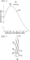
- FIG. 11 is a graph 1100 including a plot 1102 of gain versus zenith angle for a QHA antenna element of the earth terminal phased array antenna shown in FIGs. 8 and 9 .
- the abscissa in FIG. 6 indicates earth terminal zenith angle ⁇ T in radians and the ordinate represents signal strength in relative units.
- each element of a phased array antenna of an earth terminal exhibits a peak gain at an angle above 0.785 radians (45°).
- FIG. 12 is a plan view of the phased array antenna 800 shown in FIGs. 8-9 showing how antenna elements are grouped together.
- the QHA's 802 are grouped into four groups of three including a first group 1202, a second group 1204, a third group 1206 and a fourth group 1208. Each group can be served by essentially a duplicate of the same circuit design as shown in FIG. 13 and discussed below.
- FIG. 13 is a schematic of a signal distribution and signal combining network 1300 for the phased array antenna shown in FIG. 8 .
- a power amplifier 1302 for transmitting signals and a low noise amplifier 1304 for receiving signals are coupled through a transmit-receive switch (T/R) 1306 to an unbalanced port 1308 of a balun 1310.
- the balun 1310 has a 0° port 1312 coupled to an input port 1314 of a first 90° hybrid 1316.
- the balun 1310 has a 180° port 1318 coupled to an input port 1320 of a second 90° hybrid 1322.
- the first 90° hybrid 1316 has a first direct (0°) port 1324 coupled to a first 3-to-1 splitter 1326 and a first coupled (90°) port 1328 coupled to a second 3-to-1 splitter 1330.
- the second 90° hybrid 1322 has a second direct (0°) port 1332 coupled to a third 3-to-1 splitter 1336 and a second coupled (90°) port 1334 coupled to a fourth 3-to-1 splitter 1338.
- the first 1326, second 1330 third 1336 and fourth 1338 3-to-1 splitters are respectively parts of a first circuit subsection 1340, a second circuit subsection 1342, a third circuit subsection 1344, and a fourth circuit subsection 1346 which respectively serve the first group 1202, the second group 1204, the third group 1206 and the fourth group 1208 of QHA elements 802 shown in FIG. 12 .
- There are 12 digitally controlled phase shift networks 1348 (only one of which is labeled to avoid crowding the drawing), three of which are included in each circuit subsection 1340, 1342, 1344, 1346 and three of which are connected to the 3-to-1 splitter 1326, 1330, 1334, 1338 for the respective subsection 1340, 1342, 1344, 1346.
- Each digitally controlled phase shift network 1348 is coupled to through an associated QHA feed network 1350 (only one of which is labeled to avoid crowding the drawing) to a respective QHA 802. Details of a representative QHA feed network 1350 are shown in FIG. 14 which is discussed below.
- the four circuit subsections 1340, 1342, 1344, 1346 are phased at 0°, 90°, 180° and 270°. This phasing compensates for the physical relative orientations of the four circuit subsections 1340, 1342, 1344, 1346.
- FIG. 14 is a schematic of a QHA feed network 1350 used in the signal distribution and combining 1300 network shown in FIG. 13 .
- a balun 1402 comprises an unbalanced input 1404, an associated input side ground terminal 1406, and a first balanced output 1408 and a second balanced output1410 having respectively phases of 0° and 180°.
- the first (0°) balanced output 1408 is coupled to an input 1412 of a first 90° hybrid 1414 and the second (180°) balanced output 1410 is coupled to an input 1416 of a second 90° hybrid 1418.
- Each of the 90° hybrids 1414, 1418 includes an isolated port 1420 coupled to one of two terminating resistors 1422.
- the first 90° hybrid 1414 includes a 0° direct output port 1426 and a 90° coupled output port 1428.
- the second 90° hybrid 1418 due to the fact that its own input is shifted by 180 ° by the balun 1402 includes 180° direct output port 1430 and a 270° coupled output port 1432.
- the four output ports1426, 1428, 1430, 1432 of the two 90 ° hybrids are coupled to the four helical filaments 702, 704, 706, 708 (see FIG. 7 ) of the QHA 700, 802 Note that the phases, 0°, 90°, 180°, 270° are applied in order going in a circle from element to element 702, 704, 706, 708.
- the QHA 700, 802 is provided with the appropriately phased signals to operate in circularly polarized mode. It is worth mentioning that what is referred to as an "input” above will serve as an "output" when the phased array antenna 800 is operating in receive mode.
- FIG. 15 is a schematic of a digitally controlled discrete phase shifter 1348 used in the signal distribution and combining network 1300 shown in FIG. 13 .
- phase delay elements including a 22.5° phase delay 1506, a 45° phase delay 1508, a 90° phase delay 1510 and a 180° phase delay 1512.
- the phase delays 1506, 1508, 1510, 1512 can, for example, be implemented as lengths of transmission line.
- the phase delays 1506, 1508, 1510, 1512 can be selectively bypassed by selective actuation of a plurality of digitally controlled switches 1514.
- the switches 1514 are controlled by a binary number expression of a desired phase shift that is applied to a binary input 1516 that are coupled to the switches 1514.
- a least significant bit bo controls bypassing of the smallest 22.5° phase delay 1506
- a most significant bit b 3 controls bypassing of the largest 180° phase delay 1512, and so on.
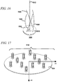
- FIG. 16 is front view of a quadrifilar helical antenna (QHA) 1600 for use in an earth terminal phased array antenna according to an alternative embodiment of the invention.
- the QHA 1600 includes a set of four helical filaments including a first helical filament 1602, a second helical filament 1604, a third helical filament 1606 and a fourth helical filament 1608 connected to a printed circuit board 1610.
- the helical filaments 702, 704, 706, 708 wind about a virtual central axis 1612 of the QHA.
- the helical filaments 702, 704, 706, 708 may be formed on a piece of flex circuit (not shown) that is formed into cylinder or on a cylindrical surface of a dielectric cylinder.
- Each of the helical filaments 1602, 1604, 1606, 1608 completes between 0.22 and 0.3 turns (e.g., 0.26 turns according to an exemplary embodiment) around the virtual central axis 1612 of the QHA 1600 and each of the helical filaments 1602, 1604, 1606, 1608 has a length between 0.2125 ⁇ and 0.2875 ⁇ , (e.g., 0.25 ⁇ according to an exemplary embodiment) ⁇ being the wavelength corresponding to the center frequency of operation of the QHA 1600.
- a virtual cylindrical surface on which the helical filaments 1602, 1604, 1606, 1608 are positioned has a diameter between 12.92 mm and 17.48 mm (e.g.,15.2 mm according to an exemplary embodiment) and the helical filaments 1602, 1604, 1606, 1608 are characterized by a helical pitch angle ⁇ of between 62° and 84° (e.g., 73.3° according to an exemplary embodiment). Additional design aspects involved in the forgoing objectives related to form of the gain pattern have to do with the design of the array shown in FIG. 17 and discussed below.
- FIG. 17 is a perspective view of an earth terminal phased array antenna 1700 that includes 12 of the QHAs 1600 shown in FIG. 16 according to another embodiment of the invention.
- the phased array antenna 1700 includes a set 1702 of 12 of the QHAs 1600 shown in FIG. 16 .
- the discussion above concerning the arrangement of the QHA's 802 of the phased array antenna 800 also applies to the QHAs 1702 of the phased array antenna 1700.
- a thirteenth QHA is added to the center of the phased array antennas 800, 1700.
- a number of QHA's different than 12 and 13 is provided in phased array antennas for use in the systems described herein.
Landscapes
- Physics & Mathematics (AREA)
- Engineering & Computer Science (AREA)
- Astronomy & Astrophysics (AREA)
- General Physics & Mathematics (AREA)
- Remote Sensing (AREA)
- Aviation & Aerospace Engineering (AREA)
- Variable-Direction Aerials And Aerial Arrays (AREA)
Claims (11)
- Phasengesteuerte Gruppenantenne (800) zur Verwendung in einem Erdterminal (108) eines LEO-(Low Earth Orbit)-Satellitenkommunikationssystems (100), wobei die phasengesteuerte Gruppenantenne (800) Folgendes umfasst:einen Satz von Antennenelementen (802), wobei jedes Antennenelement (806, 808) eine quadrifilare Helixantenne (700) ist;wobei die Antennenelemente (806, 808) auf einer Ebene liegen und um eine Distanz von 0,4 λ bis 0,45λ voneinander beabstandet sind, wobei λ eine Wellenlänge ist, die einer Betriebsfrequenz der phasengesteuerten Gruppenantenne (800) entspricht;wobei jedes Antennenelement (806, 808) einen Satz von vier Filamenten einschließlich eines ersten Filaments (702), eines zweiten Filaments (704), eines dritten Filaments (706) und eines vierten Filaments (708) umfasst, die sich schraubenförmig um eine Elementmittellinie (712) winden, und wobei jedes Filament (702, 704, 706, 708) einen schraubenförmigen Steigungswinkel α zwischen 62° und 84° aufweist.
- Phasengesteuerte Gruppenantenne (800) zur Verwendung im LEO-Satellitenkommunikationssystem (100) nach Anspruch 1, wobei das erste Filament (702), das zweite Filament (704), das dritte Filament (706) und das vierte Filament (708) jeweils eine Länge zwischen 0,7λ und 0,8λ haben und jedes Filament (702, 704, 706, 708) zwischen 0,5 und 0,75 Windungen um die Elementmittellinie (712) vollendet.
- Phasengesteuerte Gruppenantenne (800) zur Verwendung im LEO-Satellitenkommunikationssystem (100) nach Anspruch 1, wobei das erste Filament (702), das zweite Filament (704), das dritte Filament (706) und das vierte Filament (708) jeweils eine Länge zwischen 0,2125 λ und 0,2875 λ haben und jedes Filament (702, 704, 706, 708) zwischen 0,22 und 0,3 Windungen um die Elementmittellinie (712) vollendet.
- Phasengesteuerte Gruppenantenne (800) zur Verwendung im LEO-Satellitenkommunikationssystem (100) nach Anspruch 1, wobei jedes Element (702, 704, 706, 708) mit einem Speisenetzwerk (1350) versehen ist, das Folgendes beinhaltet:einen Balun (1402) mit einem ersten Balunanschluss (1404), einem zweiten Balunanschluss (1408) und einem dritten Balunanschluss (1410), wobei der erste Balunanschluss (1404) so konfiguriert ist, dass er als Eingang und Ausgang des Elements (702, 704, 706, 708) dient;einen ersten 90°-Hybrid (1414) und einen zweiten 90°-Hybrid (1418), wobei jeder 90°-Hybrid (1414, 1418) einen ersten Hybrid-Port (1412, 1416), einen zweiten Hybrid-Port (1426, 1430), einen dritten Hybrid-Port (1428, 1432) und einen vierten Hybrid-Port (1420) beinhaltet, wobei der erste Hybrid-Port (1412) des ersten 90°-Hybrids mit dem zweiten Balunanschluss (1408) gekoppelt ist, der erste Hybrid-Port (1416) des zweiten 90°-Hybrids (1418) mit dem dritten Balunanschluss (1410) gekoppelt ist,der zweite Hybrid-Port (1426) des ersten 90°-Hybrids (1414) mit dem ersten Filament (702) gekoppelt ist;der dritte Hybrid-Port (1428) des ersten 90°-Hybrids (1414) mit dem zweiten Filament (704) gekoppelt ist;der zweite Hybrid-Port (1430) des zweiten 90°-Hybrids (1418) mit dem dritten Filament (706) gekoppelt ist; undder dritte Hybrid-Port (1432) des zweiten 90°-Hybrids (1418) mit dem vierten Filament (708) gekoppelt ist.
- Phasengesteuerte Gruppenantenne (800) zur Verwendung im LEO-Satellitenkommunikationssystem (100) nach Anspruch 4, wobei:der vierte Hybrid-Port (1420) des ersten 90°-Hybrids (1414) mit Masse gekoppelt ist; der vierte Hybrid-Port (1420) des zweiten 90°-Hybrids (1418) mit Masse gekoppelt ist.
- Phasengesteuerte Gruppenantenne (800) zur Verwendung im LEO-Satellitenkommunikationssystem (100) nach Anspruch 5, wobei:der vierte Hybrid-Port (1420) des ersten 90°-Hybrids (1414) über einen ersten Abschlusswiderstand (1422) mit Masse gekoppelt ist; undder vierte Hybrid-Port (1420) des zweiten 90°-Hybrids (1418) über einen zweiten Abschlusswiderstand (1422) mit Masse gekoppelt ist.
- Phasengesteuerte Gruppenantenne (800) für den Einsatz im LEO-Satellitenkommunikationssystem (100) nach Anspruch 1, wobei:
der Satz von Antennenelementen (802) eine erste Gruppe von Antennenelementen (1202), eine zweite Gruppe von Antennenelementen (1204), eine dritte Gruppe von Antennenelementen (1206) und eine vierte Gruppe von Antennenelementen (1208) umfasst und die phasengesteuerte Gruppenantenne (800) ferner ein Signalverteilungs- und Kombinationsnetzwerk (1300) umfasst, das Folgendes umfasst:einen Balun (1310), der einen unsymmetrischen Seitenport (1308), einen symmetrischen 0°-Port (1312) und einen symmetrischen 180°-Port (1318) beinhaltet;einen ersten 90°-Hybrid (1316) mit: einem Eingangsport (1314), der mit dem symmetrischen 0°- Port (1312) des Baluns (1310) gekoppelt ist, einem ersten 0°-Direktport (1324), der mit der ersten Gruppe von Antennenelementen (1202) gekoppelt ist, und einem ersten 90° gekoppelten Port (1328), der mit der zweiten Gruppe von Antennenelementen (1204) gekoppelt ist;einen zweiten 90°-Hybrid (1322) mit: einem Eingangsport (1320), der mit dem symmetrischen 180°-Port (1318) des Baluns (1310) gekoppelt ist, einem zweiten 0°-Direktport (1332), der mit der dritten Gruppe von Antennenelementen (1206) gekoppelt ist, und einem zweiten 90° gekoppelten Port (1334), der mit der vierten Gruppe von Antennenelementen (1208) gekoppelt ist. - Phasengesteuerte Gruppenantenne (800) nach Anspruch 7, wobei:der erste 0°-Direktanschluss (1324) über einen ersten Splitter (1326) mit mehreren einzelnen Antennenelementen der ersten Gruppe von Antennenelementen (1202) gekoppelt ist;der erste 90° gekoppelte Port (1328) über einen zweiten Splitter (1330) mit der zweiten Gruppe von Antennenelementen (1204) gekoppelt ist;der zweite 0°-Direktanschluss (1332) über einen dritten Splitter (1336) mit mehreren einzelnen Antennenelementen der dritten Gruppe von Antennenelementen (1206) gekoppelt ist; undder zweite 90° gekoppelte Anschluss (1334) über einen vierten Splitter (1338) mit der vierten Gruppe von Antennenelementen gekoppelt ist.
- Satellitenkommunikationssystem (100), das Folgendes umfasst:einen Erdterminal (108) mit der phasengesteuerten Gruppenantenne (800) nach Anspruch 1; undeinen Satelliten (104) in einer niedrigen Erdumlaufbahn (106), wobei der genannte Satellit (104) eine Antenne mit einem ersten Antennengewinndiagramm aufweist, wobei eine Distanz zum Satelliten in Abhängigkeit von einem am Erdterminal (108) gemessenen Zenitwinkel, und das über den Azimutwinkel gemittelte erste Antennengewinndiagramm in Abhängigkeit von dem am Erdterminal (108) gemessenen Zenitwinkel, derart ist, dass ein Infrastrukturgewinn, der das über den Azimutwinkel gemittelte erste Antennengewinndiagramm, und die mit der Distanz zum Satelliten assoziierten Spreizverluste in Abhängigkeit von dem am Erdterminal (108) gemessenen Zenitwinkel kombiniert, eine Variation aufweist, die eine erste Spitze bei einem ersten Wert des am Erdterminal (108) gemessenen Zenitwinkels zeigt;wobei jedes Antennenelement (806, 808) der phasengesteuerten Gruppenantenne (800) des Erdterminals (108) ein zweites Gewinndiagramm in Abhängigkeit von dem am Erdterminal (108) gemessenen Zenitwinkel aufweist, der eine zweite Spitze bei einem zweiten Wert des am Erdterminal (108) gemessenen Zenitwinkels aufweist, der größer als der erste Wert des am Erdterminal (108) gemessenen Zenitwinkels ist.
- Satellitenkommunikationssystem (100) nach Anspruch 9, wobei sich der Satellit (102) in einer niedrigen Erdumlaufbahn (106) auf einer Bahnhöhe zwischen 663 km und 897 km befindet.
- Phasengesteuerte Gruppenantenne (800) nach Anspruch 1, wobei der Satz von Elementen (802) 12 Elemente (806, 808) umfasst.
Applications Claiming Priority (1)
| Application Number | Priority Date | Filing Date | Title |
|---|---|---|---|
| US201562152086P | 2015-04-24 | 2015-04-24 |
Publications (2)
| Publication Number | Publication Date |
|---|---|
| EP3089264A1 EP3089264A1 (de) | 2016-11-02 |
| EP3089264B1 true EP3089264B1 (de) | 2020-12-30 |
Family
ID=55806223
Family Applications (1)
| Application Number | Title | Priority Date | Filing Date |
|---|---|---|---|
| EP16166496.6A Active EP3089264B1 (de) | 2015-04-24 | 2016-04-21 | Phasengesteuerte gruppenantenne mit verbesserter verstärkung bei hohen scheitelpunkt |
Country Status (2)
| Country | Link |
|---|---|
| US (1) | US10103433B2 (de) |
| EP (1) | EP3089264B1 (de) |
Families Citing this family (7)
| Publication number | Priority date | Publication date | Assignee | Title |
|---|---|---|---|---|
| US10222445B2 (en) * | 2014-09-29 | 2019-03-05 | Maxtena, Inc. | System in which a phased array antenna emulates lower directivity antennas |
| EP3089264B1 (de) | 2015-04-24 | 2020-12-30 | Maxtena Inc | Phasengesteuerte gruppenantenne mit verbesserter verstärkung bei hohen scheitelpunkt |
| CN107546478B (zh) * | 2017-07-25 | 2021-04-20 | 西安电子科技大学 | 采用特殊方向图阵元的宽角扫描相控阵天线及设计方法 |
| US10958336B2 (en) * | 2018-05-29 | 2021-03-23 | Metawave Corporation | Phased array antenna for use with low earth orbit satellite constellations |
| CN110994157B (zh) * | 2019-12-23 | 2021-11-05 | 浙江科技学院 | 一种双螺旋移相单元的涡旋形阵列天线 |
| CN119908082A (zh) * | 2023-08-28 | 2025-04-29 | 京东方科技集团股份有限公司 | 卫星跟踪方法、跟踪处理装置及卫星跟踪系统 |
| EP4584900A1 (de) * | 2023-11-28 | 2025-07-16 | Google LLC | Verfahren und vorrichtung zur antennenstrahlsteuerung für mobile satellitenkommunikation |
Citations (4)
| Publication number | Priority date | Publication date | Assignee | Title |
|---|---|---|---|---|
| US20040135736A1 (en) * | 2003-01-14 | 2004-07-15 | Fund Douglas Eugene | Time-delayed directional beam phased array antenna |
| US20050122262A1 (en) * | 2003-10-31 | 2005-06-09 | Hoon Ahn | Electronically steerable array antenna for satellite TV |
| US20130308722A1 (en) * | 2011-01-17 | 2013-11-21 | Telefonaktiebolaget L M Ericsson (Publ) | Active antenna arrangement for transmitting precoded signals in a communication system, base station, methods and computer programs |
| US20140313073A1 (en) * | 2013-03-15 | 2014-10-23 | Carlo Dinallo | Method and apparatus for establishing communications with a satellite |
Family Cites Families (9)
| Publication number | Priority date | Publication date | Assignee | Title |
|---|---|---|---|---|
| US5986619A (en) * | 1996-05-07 | 1999-11-16 | Leo One Ip, L.L.C. | Multi-band concentric helical antenna |
| US6002377A (en) * | 1998-05-08 | 1999-12-14 | Antcom | Quadrifilar helix antenna |
| US6049305A (en) * | 1998-09-30 | 2000-04-11 | Qualcomm Incorporated | Compact antenna for low and medium earth orbit satellite communication systems |
| GB0204014D0 (en) * | 2002-02-20 | 2002-04-03 | Univ Surrey | Improvements relating to multifilar helix antennas |
| US6812906B2 (en) * | 2002-05-03 | 2004-11-02 | Harris Corporation | Broadband quardifilar helix with high peak gain on the horizon |
| US7388559B1 (en) * | 2006-12-21 | 2008-06-17 | The Boeing Company | Reflector antenna |
| US8314750B1 (en) * | 2010-04-28 | 2012-11-20 | The United States Of America As Represented By Secretary Of The Navy | Slotted bifilar or quadrifilar helix antenna |
| EP3089264B1 (de) | 2015-04-24 | 2020-12-30 | Maxtena Inc | Phasengesteuerte gruppenantenne mit verbesserter verstärkung bei hohen scheitelpunkt |
| US9666948B1 (en) * | 2016-02-02 | 2017-05-30 | Northrop Grumman Systems Corporation | Compact cross-link antenna for next generation global positioning satellite constellation |
-
2016
- 2016-04-21 EP EP16166496.6A patent/EP3089264B1/de active Active
- 2016-04-21 US US15/134,444 patent/US10103433B2/en active Active
Patent Citations (4)
| Publication number | Priority date | Publication date | Assignee | Title |
|---|---|---|---|---|
| US20040135736A1 (en) * | 2003-01-14 | 2004-07-15 | Fund Douglas Eugene | Time-delayed directional beam phased array antenna |
| US20050122262A1 (en) * | 2003-10-31 | 2005-06-09 | Hoon Ahn | Electronically steerable array antenna for satellite TV |
| US20130308722A1 (en) * | 2011-01-17 | 2013-11-21 | Telefonaktiebolaget L M Ericsson (Publ) | Active antenna arrangement for transmitting precoded signals in a communication system, base station, methods and computer programs |
| US20140313073A1 (en) * | 2013-03-15 | 2014-10-23 | Carlo Dinallo | Method and apparatus for establishing communications with a satellite |
Also Published As
| Publication number | Publication date |
|---|---|
| US20170214135A1 (en) | 2017-07-27 |
| US10103433B2 (en) | 2018-10-16 |
| EP3089264A1 (de) | 2016-11-02 |
Similar Documents
| Publication | Publication Date | Title |
|---|---|---|
| US10103433B2 (en) | Phased array antenna with improved gain at high zenith angles | |
| US11700056B2 (en) | Phased array antenna for use with low earth orbit satellite constellations | |
| EP3334060B1 (de) | Beschleunigtes satellitenerfassungsverfahren durch erweiterung des sichtfelds einer konfigurierbaren phasengesteuerten gruppenantenne. | |
| US8049667B2 (en) | GPS antenna array and system for adaptively suppressing multiple interfering signals in azimuth and elevation | |
| US10283876B1 (en) | Dual-polarized, planar slot-aperture antenna element | |
| US9666948B1 (en) | Compact cross-link antenna for next generation global positioning satellite constellation | |
| EP2135325A1 (de) | Zweifach gestaffelte vertikal polarisierte antenne mit strahlbreite mit variablem azimut für ein drahtloses netz | |
| WO2016063748A1 (ja) | 無線通信モジュール | |
| US12283758B2 (en) | System and methods for use with electronically steerable antennas for wireless communications | |
| EP3830901A1 (de) | Geteiltes diamantantennenelement zur steuerung des azimutmusters in verschiedenen anordnungskonfigurationen | |
| US20250273872A1 (en) | Shared transmit and receive aperture linear array | |
| AU2021274401B2 (en) | Reconfigurable, flexible multi-user electronically steered antenna (esa) terminal | |
| US8604997B1 (en) | Vertical array antenna | |
| US10673148B1 (en) | Circularly symmetric tightly coupled dipole array with non-coincident phase center | |
| US20220294112A1 (en) | Unit cell for a reconfigurable antenna | |
| US7656351B1 (en) | Method of designing a low cost multibeam phased array antenna for communicating with geostationary satellites | |
| USH605H (en) | Multi-element adaptive antenna array | |
| CN105305086A (zh) | 一种抗干扰微带阵列天线 | |
| CN112310662A (zh) | 具有带增强型半功率束宽控制的天线阵列的蜂窝通信系统 | |
| Bodnar et al. | A novel array antenna for MSAT applications | |
| EP4241331B1 (de) | Selbstkompensierendes analoges strahlformungswanderwellenphasenarray | |
| EP3236532B1 (de) | Dynamisch zugeordnete breitbandige multi-tap-antenne | |
| Wang et al. | A Two-Dimensional Transmitting Antenna Array Controlled by One-Dimensional Receiving Antenna Arrays for Microwave Power Transmission from a Geostationary Satellite to the Earth | |
| JP2016127441A (ja) | アンテナ装置 | |
| Stirland et al. | Mobile antenna developments in EADS Astrium |
Legal Events
| Date | Code | Title | Description |
|---|---|---|---|
| PUAI | Public reference made under article 153(3) epc to a published international application that has entered the european phase |
Free format text: ORIGINAL CODE: 0009012 |
|
| AK | Designated contracting states |
Kind code of ref document: A1 Designated state(s): AL AT BE BG CH CY CZ DE DK EE ES FI FR GB GR HR HU IE IS IT LI LT LU LV MC MK MT NL NO PL PT RO RS SE SI SK SM TR |
|
| AX | Request for extension of the european patent |
Extension state: BA ME |
|
| 17P | Request for examination filed |
Effective date: 20170428 |
|
| RBV | Designated contracting states (corrected) |
Designated state(s): AL AT BE BG CH CY CZ DE DK EE ES FI FR GB GR HR HU IE IS IT LI LT LU LV MC MK MT NL NO PL PT RO RS SE SI SK SM TR |
|
| STAA | Information on the status of an ep patent application or granted ep patent |
Free format text: STATUS: REQUEST FOR EXAMINATION WAS MADE |
|
| STAA | Information on the status of an ep patent application or granted ep patent |
Free format text: STATUS: EXAMINATION IS IN PROGRESS |
|
| 17Q | First examination report despatched |
Effective date: 20190902 |
|
| GRAP | Despatch of communication of intention to grant a patent |
Free format text: ORIGINAL CODE: EPIDOSNIGR1 |
|
| STAA | Information on the status of an ep patent application or granted ep patent |
Free format text: STATUS: GRANT OF PATENT IS INTENDED |
|
| INTG | Intention to grant announced |
Effective date: 20200713 |
|
| RIN1 | Information on inventor provided before grant (corrected) |
Inventor name: PAULOTTO, SIMONE Inventor name: LICUL, STANISLAV Inventor name: DINALLO, CARLO Inventor name: CUMMINGS, NATHAN |
|
| GRAS | Grant fee paid |
Free format text: ORIGINAL CODE: EPIDOSNIGR3 |
|
| GRAA | (expected) grant |
Free format text: ORIGINAL CODE: 0009210 |
|
| STAA | Information on the status of an ep patent application or granted ep patent |
Free format text: STATUS: THE PATENT HAS BEEN GRANTED |
|
| AK | Designated contracting states |
Kind code of ref document: B1 Designated state(s): AL AT BE BG CH CY CZ DE DK EE ES FI FR GB GR HR HU IE IS IT LI LT LU LV MC MK MT NL NO PL PT RO RS SE SI SK SM TR |
|
| REG | Reference to a national code |
Ref country code: GB Ref legal event code: FG4D |
|
| REG | Reference to a national code |
Ref country code: DE Ref legal event code: R096 Ref document number: 602016050486 Country of ref document: DE |
|
| REG | Reference to a national code |
Ref country code: AT Ref legal event code: REF Ref document number: 1350860 Country of ref document: AT Kind code of ref document: T Effective date: 20210115 |
|
| REG | Reference to a national code |
Ref country code: IE Ref legal event code: FG4D |
|
| PG25 | Lapsed in a contracting state [announced via postgrant information from national office to epo] |
Ref country code: FI Free format text: LAPSE BECAUSE OF FAILURE TO SUBMIT A TRANSLATION OF THE DESCRIPTION OR TO PAY THE FEE WITHIN THE PRESCRIBED TIME-LIMIT Effective date: 20201230 Ref country code: RS Free format text: LAPSE BECAUSE OF FAILURE TO SUBMIT A TRANSLATION OF THE DESCRIPTION OR TO PAY THE FEE WITHIN THE PRESCRIBED TIME-LIMIT Effective date: 20201230 Ref country code: NO Free format text: LAPSE BECAUSE OF FAILURE TO SUBMIT A TRANSLATION OF THE DESCRIPTION OR TO PAY THE FEE WITHIN THE PRESCRIBED TIME-LIMIT Effective date: 20210330 Ref country code: GR Free format text: LAPSE BECAUSE OF FAILURE TO SUBMIT A TRANSLATION OF THE DESCRIPTION OR TO PAY THE FEE WITHIN THE PRESCRIBED TIME-LIMIT Effective date: 20210331 |
|
| REG | Reference to a national code |
Ref country code: AT Ref legal event code: MK05 Ref document number: 1350860 Country of ref document: AT Kind code of ref document: T Effective date: 20201230 |
|
| PG25 | Lapsed in a contracting state [announced via postgrant information from national office to epo] |
Ref country code: BG Free format text: LAPSE BECAUSE OF FAILURE TO SUBMIT A TRANSLATION OF THE DESCRIPTION OR TO PAY THE FEE WITHIN THE PRESCRIBED TIME-LIMIT Effective date: 20210330 Ref country code: SE Free format text: LAPSE BECAUSE OF FAILURE TO SUBMIT A TRANSLATION OF THE DESCRIPTION OR TO PAY THE FEE WITHIN THE PRESCRIBED TIME-LIMIT Effective date: 20201230 Ref country code: LV Free format text: LAPSE BECAUSE OF FAILURE TO SUBMIT A TRANSLATION OF THE DESCRIPTION OR TO PAY THE FEE WITHIN THE PRESCRIBED TIME-LIMIT Effective date: 20201230 |
|
| REG | Reference to a national code |
Ref country code: NL Ref legal event code: MP Effective date: 20201230 |
|
| PG25 | Lapsed in a contracting state [announced via postgrant information from national office to epo] |
Ref country code: HR Free format text: LAPSE BECAUSE OF FAILURE TO SUBMIT A TRANSLATION OF THE DESCRIPTION OR TO PAY THE FEE WITHIN THE PRESCRIBED TIME-LIMIT Effective date: 20201230 |
|
| REG | Reference to a national code |
Ref country code: LT Ref legal event code: MG9D |
|
| PG25 | Lapsed in a contracting state [announced via postgrant information from national office to epo] |
Ref country code: CZ Free format text: LAPSE BECAUSE OF FAILURE TO SUBMIT A TRANSLATION OF THE DESCRIPTION OR TO PAY THE FEE WITHIN THE PRESCRIBED TIME-LIMIT Effective date: 20201230 Ref country code: EE Free format text: LAPSE BECAUSE OF FAILURE TO SUBMIT A TRANSLATION OF THE DESCRIPTION OR TO PAY THE FEE WITHIN THE PRESCRIBED TIME-LIMIT Effective date: 20201230 Ref country code: NL Free format text: LAPSE BECAUSE OF FAILURE TO SUBMIT A TRANSLATION OF THE DESCRIPTION OR TO PAY THE FEE WITHIN THE PRESCRIBED TIME-LIMIT Effective date: 20201230 Ref country code: LT Free format text: LAPSE BECAUSE OF FAILURE TO SUBMIT A TRANSLATION OF THE DESCRIPTION OR TO PAY THE FEE WITHIN THE PRESCRIBED TIME-LIMIT Effective date: 20201230 Ref country code: SK Free format text: LAPSE BECAUSE OF FAILURE TO SUBMIT A TRANSLATION OF THE DESCRIPTION OR TO PAY THE FEE WITHIN THE PRESCRIBED TIME-LIMIT Effective date: 20201230 Ref country code: RO Free format text: LAPSE BECAUSE OF FAILURE TO SUBMIT A TRANSLATION OF THE DESCRIPTION OR TO PAY THE FEE WITHIN THE PRESCRIBED TIME-LIMIT Effective date: 20201230 Ref country code: PT Free format text: LAPSE BECAUSE OF FAILURE TO SUBMIT A TRANSLATION OF THE DESCRIPTION OR TO PAY THE FEE WITHIN THE PRESCRIBED TIME-LIMIT Effective date: 20210430 |
|
| PG25 | Lapsed in a contracting state [announced via postgrant information from national office to epo] |
Ref country code: PL Free format text: LAPSE BECAUSE OF FAILURE TO SUBMIT A TRANSLATION OF THE DESCRIPTION OR TO PAY THE FEE WITHIN THE PRESCRIBED TIME-LIMIT Effective date: 20201230 Ref country code: AT Free format text: LAPSE BECAUSE OF FAILURE TO SUBMIT A TRANSLATION OF THE DESCRIPTION OR TO PAY THE FEE WITHIN THE PRESCRIBED TIME-LIMIT Effective date: 20201230 |
|
| PG25 | Lapsed in a contracting state [announced via postgrant information from national office to epo] |
Ref country code: IS Free format text: LAPSE BECAUSE OF FAILURE TO SUBMIT A TRANSLATION OF THE DESCRIPTION OR TO PAY THE FEE WITHIN THE PRESCRIBED TIME-LIMIT Effective date: 20210430 |
|
| REG | Reference to a national code |
Ref country code: DE Ref legal event code: R097 Ref document number: 602016050486 Country of ref document: DE |
|
| PG25 | Lapsed in a contracting state [announced via postgrant information from national office to epo] |
Ref country code: AL Free format text: LAPSE BECAUSE OF FAILURE TO SUBMIT A TRANSLATION OF THE DESCRIPTION OR TO PAY THE FEE WITHIN THE PRESCRIBED TIME-LIMIT Effective date: 20201230 Ref country code: IT Free format text: LAPSE BECAUSE OF FAILURE TO SUBMIT A TRANSLATION OF THE DESCRIPTION OR TO PAY THE FEE WITHIN THE PRESCRIBED TIME-LIMIT Effective date: 20201230 |
|
| PLBE | No opposition filed within time limit |
Free format text: ORIGINAL CODE: 0009261 |
|
| STAA | Information on the status of an ep patent application or granted ep patent |
Free format text: STATUS: NO OPPOSITION FILED WITHIN TIME LIMIT |
|
| PG25 | Lapsed in a contracting state [announced via postgrant information from national office to epo] |
Ref country code: DK Free format text: LAPSE BECAUSE OF FAILURE TO SUBMIT A TRANSLATION OF THE DESCRIPTION OR TO PAY THE FEE WITHIN THE PRESCRIBED TIME-LIMIT Effective date: 20201230 Ref country code: ES Free format text: LAPSE BECAUSE OF FAILURE TO SUBMIT A TRANSLATION OF THE DESCRIPTION OR TO PAY THE FEE WITHIN THE PRESCRIBED TIME-LIMIT Effective date: 20201230 Ref country code: MC Free format text: LAPSE BECAUSE OF FAILURE TO SUBMIT A TRANSLATION OF THE DESCRIPTION OR TO PAY THE FEE WITHIN THE PRESCRIBED TIME-LIMIT Effective date: 20201230 |
|
| 26N | No opposition filed |
Effective date: 20211001 |
|
| PG25 | Lapsed in a contracting state [announced via postgrant information from national office to epo] |
Ref country code: LU Free format text: LAPSE BECAUSE OF NON-PAYMENT OF DUE FEES Effective date: 20210421 |
|
| REG | Reference to a national code |
Ref country code: BE Ref legal event code: MM Effective date: 20210430 |
|
| PG25 | Lapsed in a contracting state [announced via postgrant information from national office to epo] |
Ref country code: CH Free format text: LAPSE BECAUSE OF NON-PAYMENT OF DUE FEES Effective date: 20210430 Ref country code: LI Free format text: LAPSE BECAUSE OF NON-PAYMENT OF DUE FEES Effective date: 20210430 |
|
| PG25 | Lapsed in a contracting state [announced via postgrant information from national office to epo] |
Ref country code: SI Free format text: LAPSE BECAUSE OF FAILURE TO SUBMIT A TRANSLATION OF THE DESCRIPTION OR TO PAY THE FEE WITHIN THE PRESCRIBED TIME-LIMIT Effective date: 20201230 |
|
| PG25 | Lapsed in a contracting state [announced via postgrant information from national office to epo] |
Ref country code: IE Free format text: LAPSE BECAUSE OF NON-PAYMENT OF DUE FEES Effective date: 20210421 |
|
| PG25 | Lapsed in a contracting state [announced via postgrant information from national office to epo] |
Ref country code: IS Free format text: LAPSE BECAUSE OF FAILURE TO SUBMIT A TRANSLATION OF THE DESCRIPTION OR TO PAY THE FEE WITHIN THE PRESCRIBED TIME-LIMIT Effective date: 20210430 |
|
| PG25 | Lapsed in a contracting state [announced via postgrant information from national office to epo] |
Ref country code: BE Free format text: LAPSE BECAUSE OF NON-PAYMENT OF DUE FEES Effective date: 20210430 |
|
| PG25 | Lapsed in a contracting state [announced via postgrant information from national office to epo] |
Ref country code: HU Free format text: LAPSE BECAUSE OF FAILURE TO SUBMIT A TRANSLATION OF THE DESCRIPTION OR TO PAY THE FEE WITHIN THE PRESCRIBED TIME-LIMIT; INVALID AB INITIO Effective date: 20160421 |
|
| PG25 | Lapsed in a contracting state [announced via postgrant information from national office to epo] |
Ref country code: CY Free format text: LAPSE BECAUSE OF FAILURE TO SUBMIT A TRANSLATION OF THE DESCRIPTION OR TO PAY THE FEE WITHIN THE PRESCRIBED TIME-LIMIT Effective date: 20201230 |
|
| PG25 | Lapsed in a contracting state [announced via postgrant information from national office to epo] |
Ref country code: SM Free format text: LAPSE BECAUSE OF FAILURE TO SUBMIT A TRANSLATION OF THE DESCRIPTION OR TO PAY THE FEE WITHIN THE PRESCRIBED TIME-LIMIT Effective date: 20201230 |
|
| PG25 | Lapsed in a contracting state [announced via postgrant information from national office to epo] |
Ref country code: MK Free format text: LAPSE BECAUSE OF FAILURE TO SUBMIT A TRANSLATION OF THE DESCRIPTION OR TO PAY THE FEE WITHIN THE PRESCRIBED TIME-LIMIT Effective date: 20201230 |
|
| PG25 | Lapsed in a contracting state [announced via postgrant information from national office to epo] |
Ref country code: TR Free format text: LAPSE BECAUSE OF FAILURE TO SUBMIT A TRANSLATION OF THE DESCRIPTION OR TO PAY THE FEE WITHIN THE PRESCRIBED TIME-LIMIT Effective date: 20201230 |
|
| PG25 | Lapsed in a contracting state [announced via postgrant information from national office to epo] |
Ref country code: MT Free format text: LAPSE BECAUSE OF FAILURE TO SUBMIT A TRANSLATION OF THE DESCRIPTION OR TO PAY THE FEE WITHIN THE PRESCRIBED TIME-LIMIT Effective date: 20201230 |
|
| PGFP | Annual fee paid to national office [announced via postgrant information from national office to epo] |
Ref country code: DE Payment date: 20250529 Year of fee payment: 10 |
|
| PGFP | Annual fee paid to national office [announced via postgrant information from national office to epo] |
Ref country code: GB Payment date: 20250527 Year of fee payment: 10 |
|
| PGFP | Annual fee paid to national office [announced via postgrant information from national office to epo] |
Ref country code: FR Payment date: 20250526 Year of fee payment: 10 |