EP3089161A1 - Decoding device, method, and program - Google Patents
Decoding device, method, and program Download PDFInfo
- Publication number
- EP3089161A1 EP3089161A1 EP14873206.8A EP14873206A EP3089161A1 EP 3089161 A1 EP3089161 A1 EP 3089161A1 EP 14873206 A EP14873206 A EP 14873206A EP 3089161 A1 EP3089161 A1 EP 3089161A1
- Authority
- EP
- European Patent Office
- Prior art keywords
- gain
- linear interpolation
- interpolation
- values
- value
- Prior art date
- Legal status (The legal status is an assumption and is not a legal conclusion. Google has not performed a legal analysis and makes no representation as to the accuracy of the status listed.)
- Granted
Links
- 238000000034 method Methods 0.000 title claims abstract description 36
- 238000012545 processing Methods 0.000 claims abstract description 166
- 238000005516 engineering process Methods 0.000 abstract description 47
- 238000004364 calculation method Methods 0.000 description 26
- 102100031476 Cytochrome P450 1A1 Human genes 0.000 description 18
- 101000941690 Homo sapiens Cytochrome P450 1A1 Proteins 0.000 description 18
- 230000005236 sound signal Effects 0.000 description 18
- 238000010586 diagram Methods 0.000 description 16
- 108091006146 Channels Proteins 0.000 description 11
- 238000012888 cubic function Methods 0.000 description 10
- 230000000694 effects Effects 0.000 description 6
- 238000012937 correction Methods 0.000 description 5
- 230000002123 temporal effect Effects 0.000 description 4
- AYFVYJQAPQTCCC-GBXIJSLDSA-N L-threonine Chemical compound C[C@@H](O)[C@H](N)C(O)=O AYFVYJQAPQTCCC-GBXIJSLDSA-N 0.000 description 3
- 238000004891 communication Methods 0.000 description 3
- 230000006835 compression Effects 0.000 description 3
- 238000007906 compression Methods 0.000 description 3
- 230000006870 function Effects 0.000 description 3
- 230000001174 ascending effect Effects 0.000 description 2
- 238000012887 quadratic function Methods 0.000 description 2
- 230000001360 synchronised effect Effects 0.000 description 2
- 101100228469 Caenorhabditis elegans exp-1 gene Proteins 0.000 description 1
- ORFPWVRKFLOQHK-UHFFFAOYSA-N amicarbazone Chemical compound CC(C)C1=NN(C(=O)NC(C)(C)C)C(=O)N1N ORFPWVRKFLOQHK-UHFFFAOYSA-N 0.000 description 1
- 230000005540 biological transmission Effects 0.000 description 1
- 230000015556 catabolic process Effects 0.000 description 1
- 238000006731 degradation reaction Methods 0.000 description 1
- 239000000284 extract Substances 0.000 description 1
- 238000003384 imaging method Methods 0.000 description 1
- 238000012986 modification Methods 0.000 description 1
- 230000004048 modification Effects 0.000 description 1
- 230000003287 optical effect Effects 0.000 description 1
- 238000013139 quantization Methods 0.000 description 1
- 238000005070 sampling Methods 0.000 description 1
- 239000004065 semiconductor Substances 0.000 description 1
- 238000012546 transfer Methods 0.000 description 1
Images


Classifications
-
- H—ELECTRICITY
- H03—ELECTRONIC CIRCUITRY
- H03M—CODING; DECODING; CODE CONVERSION IN GENERAL
- H03M7/00—Conversion of a code where information is represented by a given sequence or number of digits to a code where the same, similar or subset of information is represented by a different sequence or number of digits
- H03M7/30—Compression; Expansion; Suppression of unnecessary data, e.g. redundancy reduction
-
- G—PHYSICS
- G10—MUSICAL INSTRUMENTS; ACOUSTICS
- G10L—SPEECH ANALYSIS OR SYNTHESIS; SPEECH RECOGNITION; SPEECH OR VOICE PROCESSING; SPEECH OR AUDIO CODING OR DECODING
- G10L19/00—Speech or audio signals analysis-synthesis techniques for redundancy reduction, e.g. in vocoders; Coding or decoding of speech or audio signals, using source filter models or psychoacoustic analysis
- G10L19/04—Speech or audio signals analysis-synthesis techniques for redundancy reduction, e.g. in vocoders; Coding or decoding of speech or audio signals, using source filter models or psychoacoustic analysis using predictive techniques
- G10L19/26—Pre-filtering or post-filtering
-
- G—PHYSICS
- G10—MUSICAL INSTRUMENTS; ACOUSTICS
- G10L—SPEECH ANALYSIS OR SYNTHESIS; SPEECH RECOGNITION; SPEECH OR VOICE PROCESSING; SPEECH OR AUDIO CODING OR DECODING
- G10L19/00—Speech or audio signals analysis-synthesis techniques for redundancy reduction, e.g. in vocoders; Coding or decoding of speech or audio signals, using source filter models or psychoacoustic analysis
- G10L19/02—Speech or audio signals analysis-synthesis techniques for redundancy reduction, e.g. in vocoders; Coding or decoding of speech or audio signals, using source filter models or psychoacoustic analysis using spectral analysis, e.g. transform vocoders or subband vocoders
-
- G—PHYSICS
- G10—MUSICAL INSTRUMENTS; ACOUSTICS
- G10L—SPEECH ANALYSIS OR SYNTHESIS; SPEECH RECOGNITION; SPEECH OR VOICE PROCESSING; SPEECH OR AUDIO CODING OR DECODING
- G10L19/00—Speech or audio signals analysis-synthesis techniques for redundancy reduction, e.g. in vocoders; Coding or decoding of speech or audio signals, using source filter models or psychoacoustic analysis
-
- H—ELECTRICITY
- H03—ELECTRONIC CIRCUITRY
- H03G—CONTROL OF AMPLIFICATION
- H03G11/00—Limiting amplitude; Limiting rate of change of amplitude ; Clipping in general
- H03G11/008—Limiting amplitude; Limiting rate of change of amplitude ; Clipping in general of digital or coded signals
-
- H—ELECTRICITY
- H03—ELECTRONIC CIRCUITRY
- H03G—CONTROL OF AMPLIFICATION
- H03G7/00—Volume compression or expansion in amplifiers
- H03G7/002—Volume compression or expansion in amplifiers in untuned or low-frequency amplifiers, e.g. audio amplifiers
-
- H—ELECTRICITY
- H03—ELECTRONIC CIRCUITRY
- H03G—CONTROL OF AMPLIFICATION
- H03G7/00—Volume compression or expansion in amplifiers
- H03G7/007—Volume compression or expansion in amplifiers of digital or coded signals
-
- H—ELECTRICITY
- H03—ELECTRONIC CIRCUITRY
- H03G—CONTROL OF AMPLIFICATION
- H03G9/00—Combinations of two or more types of control, e.g. gain control and tone control
- H03G9/005—Combinations of two or more types of control, e.g. gain control and tone control of digital or coded signals
-
- G—PHYSICS
- G10—MUSICAL INSTRUMENTS; ACOUSTICS
- G10L—SPEECH ANALYSIS OR SYNTHESIS; SPEECH RECOGNITION; SPEECH OR VOICE PROCESSING; SPEECH OR AUDIO CODING OR DECODING
- G10L19/00—Speech or audio signals analysis-synthesis techniques for redundancy reduction, e.g. in vocoders; Coding or decoding of speech or audio signals, using source filter models or psychoacoustic analysis
- G10L2019/0001—Codebooks
- G10L2019/0012—Smoothing of parameters of the decoder interpolation
-
- G—PHYSICS
- G10—MUSICAL INSTRUMENTS; ACOUSTICS
- G10L—SPEECH ANALYSIS OR SYNTHESIS; SPEECH RECOGNITION; SPEECH OR VOICE PROCESSING; SPEECH OR AUDIO CODING OR DECODING
- G10L21/00—Processing of the speech or voice signal to produce another audible or non-audible signal, e.g. visual or tactile, in order to modify its quality or its intelligibility
- G10L21/02—Speech enhancement, e.g. noise reduction or echo cancellation
- G10L21/0316—Speech enhancement, e.g. noise reduction or echo cancellation by changing the amplitude
- G10L21/0324—Details of processing therefor
- G10L21/034—Automatic adjustment
-
- H—ELECTRICITY
- H03—ELECTRONIC CIRCUITRY
- H03G—CONTROL OF AMPLIFICATION
- H03G9/00—Combinations of two or more types of control, e.g. gain control and tone control
Landscapes
- Engineering & Computer Science (AREA)
- Physics & Mathematics (AREA)
- Multimedia (AREA)
- Health & Medical Sciences (AREA)
- Audiology, Speech & Language Pathology (AREA)
- Human Computer Interaction (AREA)
- Signal Processing (AREA)
- Acoustics & Sound (AREA)
- Computational Linguistics (AREA)
- Spectroscopy & Molecular Physics (AREA)
- Theoretical Computer Science (AREA)
- Compression, Expansion, Code Conversion, And Decoders (AREA)
- Transmission Systems Not Characterized By The Medium Used For Transmission (AREA)
- Stereophonic System (AREA)
Abstract
Description
- The present technology relates to a decoding apparatus, a decoding method and a program, and, more particularly, a decoding apparatus, a decoding method and a program which make it possible to obtain sound with higher quality.
- In related art, in an audio coding technique of moving picture experts group (MPEG) advanced audio coding (AAC) (ISO/IEC14496-3:2001), it is possible to record auxiliary information of downmixing or dinamic range compression (DRC) in a bit stream and use the auxiliary information at a reproduction side according to an environment of the reproduction side (see, for example, Non-Patent Literature 1).
- Use of such auxiliary information enables an audio signal to be downmixed at the reproduction side or volume to be appropriately controlled through the DRC.
- Non-Patent Literature 1: Information technology Coding of audiovisual objects Part 3: Audio (ISO/IEC 14496-3:2001)
- For example, with the above-described coding technique, it is possible to designate DRC gain information for volume control as auxiliary information of DRC in units of a frame of an audio signal, and, at a reproduction side, by correcting volume of the audio signal based on this DRC gain information, it is possible to obtain sound with appropriate volume.
- However, a gain indicated by such DRC gain information becomes the same value for each sample within one frame of the audio signal which is a temporal signal. That is, all samples included in one frame are corrected with the same gain.
- Therefore, for example, when a magnitude of the gain indicated by the DRC gain information largely changes between frames, portions of temporal waveforms of the audio signal become discontinuous between the frames, which may cause degradation in auditory terms.
- The present technology has been made in view of such circumstances, and is directed to making it possible to obtain sound with higher quality.
- A decoding apparatus according to a first aspect of the present technology includes: a gain readout unit configured to read out encoded gain values at at least two gain sample positions of a time series signal; an interpolation information readout unit configured to read out interpolation information indicating whether the gain value at each sample position of the time series signal is obtained through linear interpolation or obtained through non-linear interpolation; and an interpolation processing unit configured to obtain the gain value at each sample position located between the two gain sample positions of the time series signal based on the gain values at the gain sample positions through linear interpolation or non-linear interpolation according to the interpolation information.
- The gain readout unit can be caused to further read out gain inclination values indicating inclination of the gain values at the gain sample positions. When the gain value is obtained through non-linear interpolation, the interpolation processing unit can be caused to obtain the gain value at each sample position located between the two gain sample positions based on the gain values and the gain inclination values at the gain sample positions.
- The decoding apparatus can further include: a limiting processing unit configured to perform limiting processing on the gain value obtained through non-linear interpolation so that the gain value becomes a value equal to or greater than a predetermined lower limit or a value equal to or less than a predetermined upper limit.
- The limiting processing unit can be caused to perform limiting processing using zero as the lower limit, limiting processing using one as the lower limit or limiting processing using one as the upper limit.
- The decoding apparatus can further include: an operation unit configured to obtain at the gain sample positions, straight lines having the gain values at the gain sample positions and having inclination indicated by the gain inclination values at the gain sample positions, and obtain differences between a gain value at an intersection of the straight lines obtained for the two gain sample positions and the gain values at the two gain sample positions. When the interpolation information is information indicating that the gain value is obtained through linear interpolation, the interpolation processing unit can be caused to obtain the gain value through linear interpolation, and, when the interpolation information is information indicating that the gain value is obtained through non-linear interpolation, the interpolation processing unit can be caused to obtain the gain value through non-linear interpolation or linear interpolation according to the differences.
- A decoding method or a program according to the first aspect of the present technology includes the steps of: reading out encoded gain values at at least two gain sample positions of a time series signal; reading out interpolation information indicating whether the gain value at each sample position of the time series signal is obtained through linear interpolation or obtained through non-linear interpolation; and obtaining the gain value at each sample position located between the two gain sample positions of the time series signal based on the gain values at the gain sample positions through linear interpolation or non-linear interpolation according to the interpolation information.
- According to the first aspect of the present technology, encoded gain values at at least two gain sample positions of a time series signal are read out. Interpolation information indicating whether the gain value at each sample position of the time series signal is obtained through linear interpolation or obtained through non-linear interpolation is read out. The gain value at each sample position located between the two gain sample positions of the time series signal based on the gain values at the gain sample positions is obtained through linear interpolation or non-linear interpolation according to the interpolation information.
- A decoding apparatus according to a second aspect of the present technology includes: a gain readout unit configured to read out encoded gain values at at least two gain sample positions of a time series signal and gain inclination values indicating inclination of the gain values; an operation unit configured to obtain at the gain sample positions, straight lines having the gain values at the gain sample positions and having inclination indicated by the gain inclination values at the gain sample positions, and obtain differences between a gain value at an intersection of the straight lines obtained for the two gain sample positions and the gain values at the two gain sample positions; and an interpolation processing unit configured to obtain the gain value at each sample position located between the two gain sample positions of the time series signal through linear interpolation or non-linear interpolation according to the differences.
- A decoding method or a program according to the second aspect of the present technology includes the steps of: reading out encoded gain values at at least two gain sample positions of a time series signal and gain inclination values indicating inclination of the gain values; obtaining at the gain sample positions, straight lines having the gain values at the gain sample positions and having inclination indicated by the gain inclination values at the gain sample positions, and obtaining differences between a gain value at an intersection of the straight lines obtained for the two gain sample positions and the gain values at the two gain sample positions; and obtaining the gain value at each sample position located between the two gain sample positions of the time series signal through linear interpolation or non-linear interpolation according to the differences.
- According to the second aspect of the present technology, encoded gain values at at least two gain sample positions of a time series signal and gain inclination values indicating inclination of the gain values are read out. At the gain sample positions, straight lines having the gain values at the gain sample positions and having inclination indicated by the gain inclination values at the gain sample positions are obtained and differences between a gain value at an intersection of the straight lines obtained for the two gain sample positions and the gain values at the two gain sample positions are obtained. The gain value at each sample position located between the two gain sample positions of the time series signal is obtained through linear interpolation or non-linear interpolation according to the differences.
- According to the first aspect and the second aspect of the present technology, it is possible to obtain sound with higher quality.
- Note that advantageous effects are not limited to the advantageous effect described herein and may be any advantageous effects described in the present disclosure.
-
- [
FIG. 1] FIG. 1 is a diagram for explaining linear interpolation of a gain according to an embodiment of the present technology. - [
FIG. 2] FIG. 2 is a diagram illustrating an example of a gain waveform according to an embodiment of the present technology. - [
FIG. 3] FIG. 3 is a diagram for explaining non-linear interpolation of a gain according to an embodiment of the present technology. - [
FIG. 4] FIG. 4 is a diagram illustrating a configuration example of an encoding apparatus according to an embodiment of the present technology. - [
FIG. 5] FIG. 5 is a flowchart explaining encoding processing according to an embodiment of the present technology. - [
FIG. 6] FIG. 6 is a diagram illustrating DRC characteristics according to an embodiment of the present technology. - [
FIG. 7] FIG. 7 is a diagram illustrating a configuration example of a decoding apparatus according to an embodiment of the present technology. - [
FIG. 8] FIG. 8 is a flowchart explaining decoding processing according to an embodiment of the present technology. - [
FIG. 9] FIG. 9 is a flowchart explaining gain decoding processing according to an embodiment of the present technology. - [
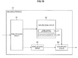
FIG. 10] FIG. 10 is a diagram illustrating a configuration example of a decoding apparatus according to an embodiment of the present technology. - [
FIG. 11] FIG. 11 is a flowchart explaining gain decoding processing according to an embodiment of the present technology. - [
FIG. 12] FIG. 12 is a diagram for explaining interpolation of a gain waveform according to an embodiment of the present technology. - [
FIG. 13] FIG. 13 is a diagram for explaining interpolation of a gain waveform according to an embodiment of the present technology. - [
FIG. 14] FIG. 14 is a diagram for explaining interpolation of a gain waveform according to an embodiment of the present technology. - [
FIG. 15] FIG. 15 is a diagram illustrating a configuration example of a decoding apparatus according to an embodiment of the present technology. - [
FIG. 16] FIG. 16 is a flowchart explaining gain decoding processing according to an embodiment of the present technology. - [
FIG. 17] FIG. 17 is a diagram explaining interpolation of a gain waveform according to an embodiment of the present technology. - [
FIG. 18] FIG. 18 is a flowchart explaining gain decoding processing according to an embodiment of the present technology. - [
FIG. 19] FIG. 19 is a diagram illustrating a configuration example of a computer according to an embodiment of the present technology. - Hereinafter, an embodiment to which the present technology is applied will be described with reference to drawings.
- The present technology relates to a technique of encoding a gain value when volume of an audio signal is corrected at a reproduction side, multiplexing a gain code string obtained by encoding the gain value and a signal code string obtained by encoding the audio signal and transmitting the multiplexed code string, and a technique of decoding these gain code string and signal code string and correcting volume of the audio signal.
- In the present technology, by designating an arbitrary value for each sample within a frame of the audio signal as a gain value for volume correction, it is possible to obtain sound with a smoother temporal waveform. By this means, it is possible to obtain sound with higher quality which does not cause a feeling of strangeness. Here, while the gain value for volume correction may be a dB value or a linear value, description will be continued below assuming that the gain value is a linear value.
- Further, when the gain value is encoded, if a gain code string is obtained by encoding only gain values at part of sample positions such as, for example, characteristic positions such as inflection points of a gain waveform and gain values which are arranged at predetermined intervals among gain values at respective sample positions within a frame, it is also possible to reduce a code amount of the gain code string.
- In this case, a decoding side of the gain code string needs to obtain an original gain waveform based on gain values at some sample positions obtained through decoding of the gain code string.
- Here, as a method for obtaining the original gain waveform, for example, there is a possible method for obtaining gain values at sample positions which are not included in the gain code string by performing linear interpolation as illustrated in
FIG. 1 . - It should be noted that
FIG. 1 indicates a gain value on a vertical axis and a sample position within a frame of an audio signal on a horizontal axis. - Further, hereinafter, a sample position of an encoded gain value which is included in a gain code string will be also specially referred to as a gain sample position. Still further, in the following, a point on a gain waveform expressed with an encoded sample position and a gain value included in the gain code string will be also simply referred to as a gain sample position.
- In the example of
FIG. 1 , information of a gain sample position G11 and a gain sample position G12 is obtained through decoding of the gain code string. - Here, a gain value at the k-th gain sample position within a frame is set as g[k], and a sample length (the number of samples) in a sample axis direction from the k-th gain sample position to the k+1-th gain sample position will be expressed as T[k].
- In this case, when it is assumed that a sample position of the k-th gain sample position G11 is n = 0, the gain sample position G11 is a point expressed with a coordinate (0, g[k]), and the gain sample position G12 is a point expressed with a coordinate (T[k], g[k+1]). Here, n is an index indicating the n-th sample position from the head of the frame.
- Further, a gain waveform between the gain sample position G11 and the gain sample position G12 obtained through linear interpolation becomes a waveform indicated with a straight line L11. That is, between the gain sample position G11 and the gain sample position G12, a gain value at each sample position is obtained through interpolation assuming that the gain value linearly changes.
- However, if the gain waveform is estimated through linear interpolation, for example, as indicated with a curve C11 in
FIG. 2 , when a smooth gain waveform is tried to be encoded, the number of points to be encoded in the gain waveform, that is, the number of gain sample positions increases. It should be noted thatFIG. 2 indicates a gain value on a vertical axis and a sample position within a frame of an audio signal on a horizontal axis. - In this example, because the gain waveform indicated with the curve C11 is a smooth waveform, if the decoding side tries to reproduce the gain waveform with a certain level of precision, it is necessary to encode gain values at a number of gain sample positions. This will increase a code amount of a bit stream obtained by multiplexing the gain code string and the signal code string, that is, increase a bit rate.
- Therefore, in the present technology, in order to make it possible to obtain sound with higher quality with a less code amount, non-linear interpolation is newly performed as appropriate in addition to linear interpolation. That is, a gain waveform is generated by performing interpolation processing using a more appropriate method selected between linear interpolation and non-linear interpolation. It should be noted that non-linear interpolation can be, for example, interpolation using a quadratic function or a cubic function.
- For example, when non-linear interpolation utilizing a cubic function is performed, a waveform indicated with a curve C21 in
FIG. 3 can be obtained as a gain waveform between the gain sample position G11 and the gain sample position G12 illustrated inFIG. 1 . It should be noted thatFIG. 3 indicates a gain value on a vertical axis and a sample position within a frame of an audio signal on a horizontal axis. Further, inFIG. 3 , the same reference numerals as those inFIG. 1 are assigned to portions corresponding to those inFIG. 1 , and explanation thereof will be omitted as appropriate. - In this example, the gain code string includes information indicating the sample position, the gain value and a gain inclination value at the gain sample position G11, and information indicating the sample position, the gain value and a gain inclination value at the gain sample position G12.
- Here, the gain inclination value is information indicating inclination of the original gain waveform at a gain sample position. Hereinafter, a gain inclination value at the k-th gain sample position will be expressed as s[k].
- In
FIG. 3 , an arrow D11 indicates the gain inclination value s[k] at the gain sample position G11, and an arrow D12 indicates a gain inclination value s[k+1] at the gain sample position G12. - At the decoding side, the gain waveform between the gain sample position G11 and the gain sample position G12 is obtained through non-linear interpolation utilizing a cubic function, and, as a result, the gain waveform indicated with the curve C21 is obtained.
- The gain waveform indicated with the curve C21 is, for example, a curve of a cubic function which passes through the gain sample position G11 and the gain sample position G12 and whose inclination at the gain sample position G11 and the gain sample position G12 is respectively s[k] and s[k+1].
- In this manner, by utilizing non-linear interpolation as appropriate, even when the gain waveform is a smooth waveform, it is possible to reproduce the gain waveform with high precision through encoding of less gain sample positions, that is, with a less code amount.
- In the present technology, for example, as a parameter for switching between linear interpolation and non-linear interpolation, interpolation mode information indicating an interpolation scheme using linear interpolation or an interpolation scheme using non-linear interpolation is included in the gain code string. The decoding side switches between linear interpolation and non-linear interpolation according to this interpolation mode information.
- Here, the interpolation mode information may be, for example, an index of two bits for switching among linear interpolation, interpolation using a quadratic function and interpolation using a cubic function, or may be a flag of one bit for switching between linear interpolation and interpolation using a cubic function which is non-linear interpolation. That is, any information may be used as the interpolation mode information if the information indicates a method for interpolating a gain waveform.
- Further, in the present technology, when the interpolation mode information is information indicating an interpolation scheme using non-linear interpolation, in addition to a gain value, a gain inclination value is included in the gain code string for each gain sample position.
- Here, the gain inclination value s[k] indicates change of a gain value per one sample. For example, the gain inclination value s[k] at the k-th gain sample position is inclination of a straight line which connects a point on the gain waveform at the k-th gain sample position and a point on the gain waveform at the next sample position of the k-th gain sample position. It should be noted that the gain inclination value may be obtained using any method if the gain inclination value indicates inclination at the gain sample position on the gain waveform.
- It should be noted that the gain inclination value as is may be stored in the gain code string, or a quantization value of the gain inclination value or an entropy encoded value such as a Huffman encoded value of the gain inclination value may be stored in the gain code string.
- Further, specific examples of a method for performing linear interpolation and a method for performing non-linear interpolation on a gain value at each sample position between two gain sample positions will be described. First, a method for performing linear interpolation will be described.
- When linear interpolation is performed using the interpolation mode information, at the decoding side, a gain value is read out for each gain sample position from the gain code string.
- Here, an index at the k-th gain sample position is set as k, and a gain value at the k-th gain sample position read out from the gain code string is set as g[k]. Further, a sample length between the k-th gain sample position and the k+1-th gain sample position is set as T[k], and it is assumed that the sample length T[k] is included in the gain code string as information indicating the sample position of the k+1-th gain sample position.
- It is now assumed that the k-th gain sample position is a head position of a frame, that is, the sample position of n = 0. In such a case, a gain value g_interpolated[n] of the sample n which is located between the k-th gain sample position and the k+1-th gain sample position and which is the n-th (where 0 ≤ n < t[k]) sample from the head is calculated using the following equation (1).
[Math. 1]
- It should be noted that in equation (1), a[k] and b[k] are values respectively obtained using the following equation (2) and equation (3).
[Math. 2]

- That is, a[k] and b[k] indicate inclination and intercept of a straight line connecting the k-th gain sample position and the k+1-th gain sample position. Therefore, in this example, as described with reference to
FIG. 1 , it is determined that the gain value linearly changes between the k-th gain sample position and the k+1-th gain sample position, and a gain value of each sample n is obtained through linear interpolation. - Subsequently, a case will be described where a gain value of the sample n between the k-th gain sample position and the k+1-th gain sample position is obtained through non-linear interpolation. Here, description will be continued with a case where interpolation using a cubic function is performed as an example of non-linear interpolation.
- When non-linear interpolation is performed according to the interpolation mode information, at the decoding side, a gain value and a gain inclination value are read out from the gain code string for each gain sample position.
- Here, in a similar manner to a case of linear interpolation, a gain value at the k-th gain sample position is set as g[k], and a sample length between the k-th gain sample position and the k+1-th gain sample position is set as T[k]. Further, a gain inclination value at the k-th gain sample position is set as s[k].
- It is now assumed that the k-th gain sample position is a head position of the frame, that is, a sample position of n = 0. In such a case, a gain value g_interpolated[n] of the sample n which is located between the k-th gain sample position and the k+1-th gain sample position and which is the n-th (where 0 ≤ n < T[k]) sample from the head is calculated using the following equation (4).
[Math. 4]
- It should be noted that, in equation (4), c[k], d[k], e[k] and f[k] are values respectively obtained using the following equation (5) to equation (8).
[Math. 5]


- In this example, as described with reference to
FIG. 3 , a gain value of each sample n is obtained through non-linear interpolation, that is, interpolation using a cubic function assuming that the gain value changes according to a cubic function indicated in equation (4) between the k-th gain sample position and the k+1-th gain sample position. - As described above, by obtaining a gain value as appropriate through non-linear interpolation, a smooth gain waveform as illustrated in, for example,
FIG. 2 can be encoded at a lower bit rate, so that it is possible to improve coding efficiency. - Subsequently, a specific embodiment to which the present technology described above is applied will be described.
-
FIG. 4 is a diagram illustrating a configuration example of an embodiment of an encoding apparatus to which the present technology is applied. - The
encoding apparatus 11 has a sound pressurelevel calculating circuit 21, again calculating circuit 22, again encoding circuit 23, asignal encoding circuit 24 and amultiplexing circuit 25. - The sound pressure
level calculating circuit 21 calculates sound pressure levels of channels constituting an input time series signal based on the input time series signal which is a supplied multichannel audio signal and obtains a representative value of sound pressure levels for each of the channels as a representative sound pressure level. - It should be noted that the representative value of the sound pressure levels is obtained for each frame of the input time series signal. Further, a frame which is used as a processing unit at the sound pressure
level calculating circuit 21 is synchronized with a frame of the input time series signal which is to be processed at thesignal encoding circuit 24 which will be described later and is made a frame having a length shorter than that of a frame at thesignal encoding circuit 24. - The sound pressure
level calculating circuit 21 supplies the obtained representative sound pressure level to thegain calculating circuit 22. The representative sound pressure level obtained in this manner indicates a representative sound pressure level of the channels of the input time series signal which is constituted with an audio signal of the predetermined number of channels such as, for example, 11.1 ch. - The
gain calculating circuit 22 calculates a gain value based on the representative sound pressure level supplied from the sound pressurelevel calculating circuit 21 and supplies the gain value to thegain encoding circuit 23. - Here, the gain value indicates a gain value for correcting volume of the input time series signal so as to be able to obtain sound of appropriate volume when the input time series signal is reproduced at the decoding side, and a gain value is calculated for each sample position within a frame at the
gain calculating circuit 22. - The
gain encoding circuit 23 encodes the gain value supplied from thegain calculating circuit 22 and supplies a gain code string obtained as a result of encoding to themultiplexing circuit 25. - Here, the gain code string includes gain information for obtaining a gain value of each gain sample position and interpolation mode information.
- The
signal encoding circuit 24 encodes the supplied input time series signal using a predetermined encoding scheme, for example, a typical encoding method typified by an encoding method using MEPG AAC and supplies a signal code string obtained as a result of encoding to themultiplexing circuit 25. - The multiplexing
circuit 25 multiples the gain code string supplied from thegain encoding circuit 23 and the signal code string supplied from thesignal encoding circuit 24 and outputs an output code string obtained as a result of multiplexing. - Specific operation of the
encoding apparatus 11 will be described next. - When the input time series signal corresponding to one frame is supplied, the
encoding apparatus 11 performs encoding processing of encoding the input time series signal and outputting the output code string. Hereinafter, encoding processing by theencoding apparatus 11 will be described with reference to the flowchart ofFIG. 5 . - In step S11, the sound pressure
level calculating circuit 21 calculates a representative sound pressure level of the input time series signal based on the supplied input time series signal and supplies the representative sound pressure level to thegain calculating circuit 22. - Specifically, the sound pressure
level calculating circuit 21 calculates sound pressure levels of respective channels constituting the input time series signal and sets a representative value of the sound pressure levels of these channels as a representative sound pressure level. - For example, in a method for calculating a sound pressure level, a maximum value, a root mean square (RMS), or the like, of frames of an audio signal of channels constituting the input time series signal is used, and a sound pressure level is obtained for each of the channels constituting the input time series signal for the frames of the input time series signal.
- Further, as a method for calculating a representative value as the representative sound pressure level, for example, a method in which a maximum value among sound pressure levels of the channels in the same frame is set as the representative value, a method in which one representative value is calculated using a specific calculation formula from the sound pressure levels of the channels, or the like, can be used. Specifically, for example, it is possible to calculate the representative value using a loudness calculation formula described in ITU-R BS.1770-2(03/2011).
- In step S12, the
gain calculating circuit 22 calculates a gain value based on the representative sound pressure level supplied from the sound pressurelevel calculating circuit 21 and supplies the gain value to thegain encoding circuit 23. - For example, the
gain calculating circuit 22 calculates the gain value according to DRC characteristics designated by a higher-order control apparatus. - The DRC characteristics designated by the higher-order control apparatus can be DRC characteristics as illustrated in, for example,
FIG. 6 . It should be noted thatFIG. 6 indicates an input sound pressure level (dBFS), that is, a representative sound pressure level on a horizontal axis, and indicates an output sound pressure level (dBFS), that is, a corrected sound pressure level when the sound pressure level (volume) of the input time series signal is corrected, on a vertical axis. - A broken line L31 and a broken line L32 respectively indicate relationship of the input and output sound pressure levels. For example, according to the DRC characteristic indicated with the broken line L31, when there is an input of the representative sound pressure level of 0 dBFS, volume is corrected so that the sound pressure level of the input time series signal becomes -27 dBFS.
- On the other hand, for example, according to the DRC characteristics indicated with the broken line L32, when there is an input of the representative sound pressure level of 0 dBFS, volume is corrected so that the sound pressure level of the input time series signal becomes -21 dBFS.
- The
gain calculating circuit 22 determines a gain value according to the DRC characteristics indicated with such a broken line L31 and a broken line L32. This gain value is outputted as a gain waveform synchronized with the frame at thesignal encoding circuit 24. That is, thegain calculating circuit 22 calculates a gain value for each of samples constituting a frame which is to be processed of the input time series signal. - More specifically, for example, the
gain calculating circuit 22 obtains a gain waveform g(J, n) in a frame J by performing calculation of the following equation (9).
[Math. 9]
- It should be noted that, in equation (9), n indicates a position of a sample which takes values from 0 to N-1 when a frame length is set as N, Gt(J) indicates the above-described DRC characteristics, that is, a target gain in the frame J determined by the input sound pressure level and the output sound pressure level.
- Further, A in equation (9) is a value determined by the following equation (10).
[Math. 10]
- In equation (10), Fs indicates a sampling frequency (Hz), Tc(J) indicates a time constant in the frame J, and exp(x) indicates an exponent function. Further, in equation (9), a gain value of the last sample in a frame immediately before the frame is used as a gain waveform g(J, n-1) when n = 0.
- Returning to explanation of the flowchart in
FIG. 5 , in step S 13, thegain encoding circuit 23 performs gain encoding processing to encode the gain value supplied from thegain calculating circuit 22. Thegain encoding circuit 23 then supplies the gain code string obtained through the gain encoding processing to themultiplexing circuit 25. - For example, the
gain encoding circuit 23 extracts a gain sample position to be encoded from the gain value at each sample position supplied from thegain calculating circuit 22, that is, a gain waveform of the frame to be processed. For example, characteristic samples such as inflection points in the gain waveform may be used as the gain sample positions, or samples arranged at predetermined intervals may be used as the gain sample positions. - The
gain encoding circuit 23 generates interpolation mode information and gain information for each of the gain sample positions extracted in this manner. - For example, the
gain encoding circuit 23 generates the interpolation mode information by performing so-called local decoding. - That is, the
gain encoding circuit 23 generates a gain waveform between two gain sample positions adjacent to each other through interpolation for linear interpolation and non-linear interpolation, and calculates a difference between the gain waveform and an actual gain waveform. Thegain encoding circuit 23 then generates information indicating an interpolation scheme in which the obtained difference is smaller as the interpolation mode information. - It should be noted that whether linear interpolation is performed or non-linear interpolation is performed may be determined using any other method. For example, it is also possible to determine that linear interpolation is performed when the gain value is the same between the gain sample position to be processed and the gain sample position immediately before the gain sample position to be processed, and the gain inclination value of the gain sample position immediately before the gain sample position to be processed is 0, and, that non-linear interpolation is performed in other cases. Alternatively, it is also possible to employ a configuration where a higher-order control apparatus designates linear interpolation or non-linear interpolation.
- Further, the
gain encoding circuit 23 encodes a sample length T[k], a gain value g[k] and a gain inclination value s[k] indicating the sample position as appropriate for each gain sample position to obtain gain information. It should be noted that, when the interpolation mode information is information indicating an interpolation scheme using linear interpolation, gain information only including the sample length and the gain value and not including the gain inclination value is generated. - The
gain encoding circuit 23 supplies the gain code string including the gain information of each gain sample position and the interpolation mode information obtained in this manner to themultiplexing circuit 25. - In
step S 14, thesignal encoding circuit 24 encodes the supplied input time series signal according to a predetermined encoding scheme and supplies the signal code string obtained as a result of encoding to themultiplexing circuit 25. - In step S15, the multiplexing
circuit 25 multiplexes the gain code string supplied from thegain encoding circuit 23 and the signal code string supplied from thesignal encoding circuit 24 and outputs the output code string obtained as a result of multiplexing. When the output code string corresponding to one frame is outputted as a bit stream in this manner, encoding processing ends. Then, encoding processing of the next frame is performed. - As described above, the
encoding apparatus 11 obtains the gain value for each sample within a frame of the input time series signal to extract the gain sample position and generates the gain code string constituted with gain information of each gain sample position and interpolation mode information. - By the gain value for each sample within a frame being determined in this manner, at the decoding side, temporal waveforms between frames of the audio signal are smoothly connected, so that it is possible to obtain sound with higher quality. Moreover, by the interpolation mode information being included in the gain code string, it is possible to reproduce a gain waveform with high precision with a less code amount by utilizing non-linear interpolation as appropriate.
- A decoding apparatus which receives the output code string outputted from the
encoding apparatus 11 as an input code string and decodes the input code string will be described next. -
FIG. 7 is a diagram illustrating a configuration example of an embodiment of the decoding apparatus to which the present technology is applied. - The
decoding apparatus 51 illustrated inFIG. 7 has ademultiplexing circuit 61, asignal decoding circuit 62, again decoding circuit 63 and again applying circuit 64. - The
demultiplexing circuit 61 demultiplexes the supplied input code string, that is, the output code string received from theencoding apparatus 11 and supplies the signal code string obtained as a result of demultiplexing to thesignal decoding circuit 62, while supplying the gain code string to thegain decoding circuit 63. - The
signal decoding circuit 62 decodes the signal code string supplied from thedemultiplexing circuit 61 and supplies a time series signal obtained as a result of decoding to thegain applying circuit 64. Here, the time series signal is, for example, an audio signal of 11.1 ch or 7.1 ch, and an audio signal of channels constituting the time series signal is set as a pulse code modulation (PCM) signal. - The
gain decoding circuit 63 decodes the gain code string supplied from thedemultiplexing circuit 61 and supplies a gain value obtained as a result of decoding to thegain applying circuit 64. Thegain decoding circuit 63 has aninterpolation processing unit 71, which calculates a gain value at each sample position of the time series signal through linear interpolation or non-linear interpolation based on the gain information and the interpolation mode information obtained from the gain code string. - The
gain applying circuit 64 corrects volume of the time series signal by adjusting a gain of the time series signal supplied from thesignal decoding circuit 62 based on the gain value supplied from thegain decoding circuit 63 and outputs an output time series signal obtained as a result of volume correction. - Subsequently, operation of the
decoding apparatus 51 will be described. - When the input code string corresponding to one frame is supplied, the
decoding apparatus 51 performs decoding processing of decoding the input code string and outputting an output time series signal. The decoding processing by thedecoding apparatus 51 will be described below with reference to the flowchart ofFIG. 8 . - In step S41, the
demultiplexing circuit 61 receives the input code string transmitted from theencoding apparatus 11 and demultiplexes the input code string, and supplies a signal code string obtained as a result of demultiplexing to thesignal decoding circuit 62, while supplying the gain code string to thegain decoding circuit 63. - In step S42, the
signal decoding circuit 62 decodes the signal code string supplied from thedemultiplexing circuit 61 and supplies a time series signal obtained as a result of decoding to thegain applying circuit 64. - In step S43, the
gain decoding circuit 63 performs gain decoding processing to decode the gain code string supplied from thedemultiplexing circuit 61 and supplies a gain value at each sample position of a frame to be processed obtained as a result of decoding to thegain applying circuit 64. It should be noted that details of the gain decoding processing will be described later. - In step S44, the
gain applying circuit 64 adjusts a gain of the time series signal supplied from thesignal decoding circuit 62 based on the gain value supplied from thegain decoding circuit 63 and outputs the obtained output time series signal. That is, each sample of the time series signal is multiplied by the gain value to be made an output time series signal with appropriate volume. - When the output time series signal is outputted, the decoding processing ends.
- As described above, the
decoding apparatus 51 decodes the gain code string, and applies the obtained gain value at each sample position to the time series signal to adjust a gain (volume) in a time domain. By adjusting a gain with a gain value determined for each sample position in this manner, it is possible to smoothly connect time waveforms between frames of the output time series signal, so that it is possible to obtain sound with higher quality. - Moreover, because a gain waveform is obtained by utilizing non-linear interpolation as appropriate, even when the gain waveform is a smooth waveform, it is possible to reproduce the gain waveform with high precision with a less code amount.
- Further, gain decoding processing corresponding to processing in step S43 of
FIG. 8 will be described with reference to the flowchart ofFIG. 9 . - In step S71, the
gain decoding circuit 63 reads out gain information at a gain sample position to be processed from the gain code string supplied from thedemultiplexing circuit 61 and decodes a sample length T[k], a gain value g[k] and a gain inclination value s[k] included as the gain information as necessary. It should be noted that when an interpolation scheme indicated by the interpolation mode information is an interpolation scheme using linear interpolation, the gain inclination value is not included in the gain information. - For example, in the gain code string, gain information and interpolation mode information at each gain sample position are stored while being arranged in ascending order of a distance from the head of the frame. Because the
gain decoding circuit 63 sequentially reads out the gain information and the interpolation mode information from the gain code string, a gain sample position is set as a gain sample position to be processed in ascending order of a distance from the head of the frame. - In step S72, the
gain decoding circuit 63 reads out the interpolation mode information at the gain sample position to be processed from the gain code string. - It should be noted that while an example where the interpolation mode information is included in the gain code string will be described here, the interpolation mode information may be included in a header, or the like, of a bit stream in which an input code string of each frame is included, or the interpolation mode information may be acquired from a higher-order control apparatus, or the like.
- In step S73, the
interpolation processing unit 71 determines whether or not the interpolation scheme indicated by the read-out interpolation mode information is a scheme using linear interpolation. - In step S73, when it is determined that the interpolation scheme is a scheme using linear interpolation, in step S74, the
interpolation processing unit 71 performs linear interpolation to generate a gain waveform. - Specifically, the
interpolation processing unit 71 performs the same calculation as that of the above-described equation (1) based on the gain value g[k] and the sample length T[k-1] at the gain sample position to be processed, and a gain value and a sample position at a gain sample position one position closer to the head of the frame from the gain sample position to be processed to generate a gain waveform between the gain sample positions. That is, a gain value at each sample position located between two gain sample positions of the time series signal is calculated, and a waveform constituted with gain values at the sample positions is set as a gain waveform. - When the gain waveform between two adjacent gain sample positons is obtained in this manner, the processing proceeds to step S76.
- On the other hand, when it is determined in step S73 that the scheme is a scheme which does not use linear interpolation, that is, a scheme using non-linear interpolation, in step S75, the
interpolation processing unit 71 performs non-linear interpolation to generate a gain waveform. - Specifically, the
interpolation processing unit 71 performs the same calculation as that of the above-described equation (4) based on the gain value g[k], the sample length T[k-1] and the gain inclination value s[k] at the gain sample position to be processed and a gain value, a sample position and a gain inclination value at a gain sample position one position closer to the head of the frame from the gain sample position to be processed to generate a gain waveform between the gain sample positions. That is, a gain value at each sample position located between two gain sample positions of the time series signal is calculated, and a waveform constituted with gain values of the sample positions is set as a gain waveform. - When the gain waveform between two adjacent gain sample positions is obtained in this manner, the processing proceeds to step S76.
- When the gain waveform between the gain sample positons is obtained through interpolation in step S74 or step S75, in step S76, the
gain decoding circuit 63 determines whether or not processing is performed for all the gain sample positions. - When it is determined in step S76 that not all of the gain sample positions are processed yet, the processing returns to step S71, and the above-described processing is repeated. That is, the next gain sample position is selected as a processing target, and a gain waveform is obtained through interpolation.
- On the other hand, when it is determined in step S76 that all of the gain sample positions are processed, the
gain decoding circuit 63 supplies a gain waveform corresponding to one frame constituted with gain values at the sample positions obtained through the processing so far to thegain applying circuit 64, and the gain decoding processing ends. When the gain decoding processing ends, then, the processing proceeds to step S44 inFIG. 8 . - The
decoding apparatus 51 obtains a gain waveform through linear interpolation or non-linear interpolation according to the interpolation mode information as described above. By obtaining a gain waveform through non-linear interpolation as appropriate according to the interpolation mode information in this manner, it is possible to reproduce a gain waveform with high precision with a less code amount. - It should be noted that while an example has been described above where the interpolation mode information is generated for each gain sample position, and the interpolation scheme is switched between linear interpolation and non-linear interpolation, one piece of the interpolation mode information may be generated for each frame. In this case, the interpolation scheme is switched between linear interpolation and non-linear interpolation in units of a frame.
- Further, the interpolation scheme may be switched between linear interpolation and non-linear interpolation in units of a plurality of frames or in units of a file. For example, when the interpolation scheme is switched in units of a file, for example, one piece of interpolation mode information is stored in a header of the bit stream. The
interpolation processing unit 71 performs interpolation processing of each frame using an interpolation scheme indicated by the interpolation mode information, that is, either the scheme using linear interpolation or the scheme using non-linear interpolation to obtain a gain waveform corresponding to one file. - By the way, the gain waveform obtained through non-linear interpolation is different from the gain waveform obtained through linear interpolation, and there is a case where a gain value at a sample position between two gain sample positions may be greater or smaller than gain values at two gain sample positions included in the gain code string.
- For example, in the example illustrated in
FIG. 3 , in part of the gain waveform indicated with the curve C21, which is obtained through non-linear interpolation, there is a portion where the gain value becomes smaller than the gain value g[k] at the gain sample position G11. Further, in part of the gain waveform indicated with the curve C21, there is also a portion where the gain value becomes greater than the gain value g[k+1] at the gain sample position G12. - Therefore, there is a case where the gain value obtained through non-linear interpolation becomes a negative (minus) value which is inappropriate as the gain value. Therefore, in order to prevent the gain value obtained through interpolation from becoming an inappropriate value, it is also possible to perform limiting on the gain value using zero as a lower limit by performing calculation of the following equation (11).
[Math. 11]
- In equation (11), between the gain value g_interpolated[n] obtained through interpolation and zero, a greater one is made a final gain value g_interoplated[n]. Accordingly, the final gain value is equal to or greater than zero, and the gain value does not become a negative value.
- Further, there is a case where it is desired to boost (amplify) the time series signal and a case where it is desired to compress (suppress) the time series signal through gain adjustment (volume correction).
- For example, when it is desired to boost the time series signal, if the gain value is smaller than one, the gain value becomes an inappropriate value. Therefore, when the time series signal is boosted, it is also possible to perform limiting on the gain value using one as a lower limit by performing calculation of the following equation (12).
[Math. 12]
- In equation (12), between the gain value g_interpolated[n] obtained through interpolation and one, a greater one is made a final gain value g_interpolated[n]. Accordingly, the gain value does not become a value less than one. In other words, the gain value is always equal to or greater than one which is the lower limit.
- Further, for example, when it is desired to compress the time series signal, if the gain value is greater than one, the gain value becomes an inappropriate value. Therefore, when the time series signal is compressed, it is also possible to perform limiting on the gain value using one as an upper limit by performing calculation of the following equation (13).
[Math. 13]
- In equation (13), between the gain value g_interpolated[n] obtained through interpolation and one, a smaller one is made a final gain value g_interpolated[n]. Accordingly, the gain value does not become a value greater than one. In other words, the gain value is always equal to or smaller than one which is the upper limit.
- When limiting processing as indicated in equation (12) or equation (13) is performed, it is only necessary to provide limiting information indicating whether the gain waveform is used for boosting or used for compression to the
gain decoding circuit 63 as information regarding the encoded gain waveform. For example, the limiting information may be supplied from a higher-order control apparatus to thegain decoding circuit 63, or the limiting information may be included in the gain code string, the header of the bit stream, or the like. - In the following, description will be continued assuming that the limiting information is included in the gain code string. In this case, in the processing of step S 13 in
FIG. 15 , the gain code string including the limiting information is generated. - By performing the limiting processing on the gain value as described above, it is possible to obtain a more appropriate gain value. By this means, it is possible to perform more appropriate gain adjustment (volume control), and, as a result, it is possible to obtain sound with higher quality.
- When limiting processing is performed on the gain value, the
decoding apparatus 51 is configured as illustrated in, for example,FIG. 10 . It should be noted that, inFIG. 10 , the same reference numerals as those inFIG. 7 are assigned to portions corresponding to those inFIG. 7 , and explanation thereof will be omitted as appropriate. - The
decoding apparatus 51 illustrated inFIG. 10 has a different configuration from that of thedecoding apparatus 51 inFIG. 7 in that a limitingprocessing unit 101 is newly provided at thegain decoding circuit 63, and has the same configuration as that of thedecoding apparatus 51 inFIG. 7 in other points. - The limiting
processing unit 101 performs limiting processing on the gain value calculated through non-linear interpolation performed by theinterpolation processing unit 71 to obtain a final gain value. - Gain decoding processing performed in the case where the
decoding apparatus 51 has the configuration illustrated inFIG. 10 will be described next. - For example, at the
decoding apparatus 51, the decoding processing described with reference toFIG. 8 is performed. However, in gain decoding processing corresponding to step S43, the gain decoding processing illustrated inFIG. 11 is performed. The gain decoding processing by thedecoding apparatus 51 inFIG. 10 will be described below with reference to the flowchart ofFIG. 11 . - It should be noted that the processing from step S101 to step S105 is the same as processing from step S71 to step S75 in
FIG. 9 , explanation thereof will be omitted. - In step S106, the limiting
processing unit 101 changes the gain value as appropriate so that the gain value does not become a negative value by performing calculation of the above-described equation (11) on the gain value at each sample position obtained through processing in step S105. - Further, the limiting
processing unit 101 obtains a final gain value by further performing calculation of either equation (12) or equation (13) on the gain value limited through calculation of equation (11) according to the limiting information included in the gain code string. - Specifically, when the limiting information included in the gain code string indicates that the gain waveform is to be used for boosting, the limiting
processing unit 101 performs calculation of equation (12) so that the gain value does not become a value less than one. - On the other hand, when the limiting information included in the gain code string indicates that the gain waveform is to be used for compression, the limiting
processing unit 101 performs calculation of equation (13) so that the gain value does not become a value greater than one. - When the gain waveform is generated through linear interpolation in step S 104 or limiting processing is performed in step S106, the processing in
step S 107 is performed, and the gain decoding processing ends. Because the processing in step S107 is the same as the processing in step S76 inFIG. 9 , explanation thereof will be omitted. - As described above, the
decoding apparatus 51 performs limiting processing on the gain value obtained through non-linear interpolation. By this means, it is possible to perform gain adjustment (volume correction) with a more appropriate gain value. It is therefore possible to obtain sound with higher quality. - Further, while, in the above description, an example has been described where the gain waveform is obtained while the interpolation scheme for interpolating the gain value is switched between linear interpolation and non-linear interpolation for each gain sample position, it is also possible to employ a configuration where non-linear interpolation is basically performed, and linear interpolation is performed only under specific conditions.
- For example, a case will be studied where the gain waveform indicated with a broken line L41 illustrated in
FIG. 12 is encoded, and the gain waveform is obtained at the decoding side through non-linear interpolation. It should be noted thatFIG. 12 indicates a gain value on a vertical axis and a sample position on a horizontal axis. - It is assumed that, at the
encoding apparatus 11, the k-th gain sample position G21 and the k+1-th gain sample position G22 are extracted, and the gain code string including gain values, sample lengths and gain inclination values at these gain sample positions is obtained. - Here, an arrow D21 indicates a gain inclination value s[k] at the gain sample position G21, and an arrow D22 indicates a gain inclination value s[k+1] at the gain sample position G22.
- It is now assumed that non-linear interpolation using a cubic function is performed at the
decoding apparatus 51 based on the gain values, the sample lengths and the gain inclination values included in the gain code string, and a gain waveform indicated with a curve C31 is obtained. - In this example, a difference between the gain waveform indicated with the curve C31 obtained through non-linear interpolation and the gain waveform indicated with a broken line L41 becomes large.
- In a scheme for obtaining a gain waveform through non-linear interpolation, when a gain waveform whose gain value linearly changes is encoded as with this example, a difference between the original gain waveform and a gain waveform obtained through non-linear interpolation upon decoding becomes large.
- To make this difference small, it is necessary to perform processing (local decoding) of adjusting a gain value and a gain inclination value to be encoded at the
encoding apparatus 11 by calculating the gain waveform obtained through non-linear interpolation, which increases a processing amount of encoding. - Therefore, in the present technology, when non-linear interpolation is performed at the
decoding apparatus 51, by allowing linear interpolation to be performed under specific conditions, a gain waveform is reproduced with high precision with a less processing amount of encoding. - Specifically, when, for example, a gain value at a sample position between the k-th gain sample position and the k+1-th gain sample position is obtained through interpolation, an intersection X[k, k+1] of two straight line l[k] and straight line 1[k+1] is obtained from gain values and gain inclination values at these gain sample positions.
- Here, the straight line l[k] is a straight line which passes through the k-th gain sample position (point) on the gain waveform and which has inclination indicated with the gain inclination value s[k]. That is, when a value of the coordinate in the sample axis direction is the same as a value of the k-th gain sample position, the straight line 1[k] is a straight line which has a gain value g[k] at the k-th gain sample position as the value of the coordinate in the gain axis direction and which has inclination indicated with the gain inclination value s[k].
- In a similar manner, the straight line 1[k+1] is a straight line which passes through the k+1-th gain sample position and which has inclination indicated with the gain inclination value s[k+1].
- Further, it is determined whether or not a distance between either the k-th gain sample position or the k+1-th gain sample position and the obtained intersection X[k, k+1] is equal to or less than a predetermined threshold. In the determination here, it is determined whether, for example, the following equation (14) holds true.
[Math. 14]
- It should be noted that, in equation (14), d_sample[k] and d_sample[k+1] respectively indicate distances from the k-th gain sample position and the k+1-th gain sample position to the intersection X[k, k+1] in the sample axis direction. Further, d_gain[k] and d_gain[k+1] respectively indicate distances from the k-th gain sample position and the k+1-th gain sample position to the intersection X[k, k+1] in the gain axis direction, that is, differences of the gain values.
- Further, thre_sample and thre_gain respectively indicate a threshold of a distance in the sample axis direction and a threshold of a distance in the gain axis direction.
- Therefore, in equation (14), when the distance d_sample[k] is equal to or less than thre_sample, and the distance d_gain[k] is equal to or less than thre_gain, or when the distance d_sample[k+1] is equal to or less than thre_sample and the distance d_gain[k+1] is equal to or less than the threshold thre_gain, a distance from the gain sample position to the intersection X[k, k+1] is equal to or less than a threshold.
- For example, when the k-th gain sample position is a head position of the frame, that is, a sample position of n = 0, the distance d_sample[k], the distance d_gain[k], the distance d_sample[k+1] and the distance d_gain[k+1] in equation (14) are respectively obtained using the following equation (15) to equation (18). Further, the threshold thre_sample and the threshold thre_gain are, for example, the threshold thre_sample = 32 and the threshold thre_gain = 0.01.
[Math. 15]


- It should be noted that, in equation (15) to equation (18), abs(x) indicates that an absolute value of x is obtained.
- When it is determined that such a conditional expression indicated with equation (14) holds true, a gain waveform is obtained through linear interpolation, that is, through calculation of the above-described equation (1). On the other hand, when the conditional expression indicated with equation (14) does not hold true, a gain waveform is obtained through non-linear interpolation, that is, through calculation of the above-described equation (4).
- For example, as illustrated in
FIG. 13 , when a gain value at each sample position between the gain sample position G31 and the gain sample position G32 is obtained through interpolation, whether or not the conditional expression indicated with equation (14) holds true is determined by specifying which of a region TR11 and a region TR12 the intersection CP11 is included in. It should be noted thatFIG. 13 indicates a gain value on a vertical axis and a sample position within a frame of the time series signal on a horizontal axis. - In
FIG. 13 , the gain sample position G31 indicates the k-th gain sample position, and the arrow D31 indicates the gain inclination value s[k] at the gain sample position G31. Therefore, the straight line L51 is a straight line l[k]. - In a similar manner, the gain sample position G32 indicates the k+1-th gain sample position, and the arrow D32 indicates the gain inclination value s[k+1] at the gain sample position G32. Therefore, the straight line L52 is a straight line 1[k+1]. The intersection CP11 which is an intersection of the straight line L51 and the straight line L52 is an intersection X[k, k+1].
- It is now assumed that the region TR11 has the gain sample position G31 in the center and has a length in a vertical direction of 2 × thre_gain, and a length in a horizontal direction of 2 × thre_sample in the drawing. In a similar manner, it is assumed that the region TR12 has the gain sample position G21 in the center and, has a length in a vertical direction of 2 × thre_gain and a length in a horizontal direction of 2 × thre_sample in the drawing.
- In this case, when the intersection CP11 is located within the region TR11 or the intersection CP11 is located within the region TR12, the conditional expression indicated with equation (14) holds true. In the example of
FIG. 13 , because the intersection CP11 is located within the region TR12, the conditional expression indicated with equation (14) holds true. - In the example illustrated in
FIG. 13 , the original gain waveform to be reproduced (restored) should have been a waveform close to a waveform constituted with the straight line L51 and the straight line L52. That is, in more detail, the waveform should have been close to the straight line L51 from the gain sample position G31 to the intersection CP11, and should have been close to the straight line L52 from the intersection CP11 to the gain sample position G32. - However, because, in this example, the intersection CP11 is located within the region TR12, and a distance between the intersection CP11 to the gain sample position G32 is sufficiently short, it is possible to determine that the original gain waveform is approximated as a straight line connecting the gain sample position G31 and the gain sample position G32.
- In this case, because at the gain waveform between the gain sample position G31 and the gain sample position G32, the gain value can substantially linearly change, it is possible to reproduce the gain waveform with higher precision by obtaining the gain waveform through linear interpolation rather than obtaining the gain waveform through non-linear interpolation. Therefore, in the present technology, when the conditional expression indicated with the above-described equation (14) holds true, the gain waveform is obtained through linear interpolation.
- Accordingly, in the example of
FIG. 13 , a gain value at each sample position between the gain sample position G31 and the gain sample position G32 is obtained through linear interpolation, and, by this means, for example, a gain waveform illustrated inFIG. 14 can be obtained. It should be noted that, inFIG. 14 , the same reference numerals as those inFIG. 13 are assigned to portions corresponding to those inFIG. 13 , and explanation thereof will be omitted as appropriate. - In
FIG. 14 , a straight line L61 connecting the gain sample position G31 and the gain sample position G32 is obtained as a gain waveform between the gain sample position G31 and the gain sample position G32. - Further, for example, also in the above-described example illustrated in
FIG. 12 , because the conditional expression indicated with equation (14) holds true, the gain waveform is obtained through linear interpolation. - In the example of
FIG. 12 , because the intersection X[k, k+1] is located at the gain sample position G22, equation (14) holds true, and a straight line connecting the gain sample position G21 and the gain sample position G22 is set as a gain waveform between the gain sample positions. Therefore, in this example, the original gain waveform is accurately reproduced. - As described above, when non-linear interpolation is basically performed while linear interpolation is performed under specific conditions, it is possible to make a difference between the original gain waveform and the decoded gain waveform smaller without increasing a processing amount of encoding.
- Moreover, by employing such a decoding scheme, because both linear interpolation and non-linear interpolation can be performed only with a scheme in which non-linear interpolation is performed, it becomes unnecessary to include the interpolation mode information in the gain code string, so that it is possible to lower a bit rate of the output code string. That is, it is possible to reduce a code amount of the output code string.
- When linear interpolation is performed under specific conditions, the
decoding apparatus 51 is configured as illustrated in, for example,FIG. 15 . It should be noted that, inFIG. 15 , the same reference numerals as those inFIG. 7 are assigned to portions corresponding to those inFIG. 7 , and explanation thereof will be omitted as appropriate. - The
decoding apparatus 51 illustrated inFIG. 15 has a different configuration from that of thedecoding apparatus 51 inFIG. 7 in that anoperation unit 131 is newly provided at thegain decoding circuit 63 and has the same configuration as that of thedecoding apparatus 51 inFIG. 7 in other points. - The
operation unit 131 performs calculation of the above-described conditional expression indicated with equation (14). - The gain decoding processing performed when the
decoding apparatus 51 is configured as illustrated inFIG. 15 will be described next. - For example, while, at the
encoding apparatus 11, the encoding processing described with reference toFIG. 5 is performed, in the gain encoding processing in step S 13, the gain code string only including the gain information and not including the interpolation mode information is generated, and the output code string obtained through multiplexing is outputted. Further, in this case, the gain information always includes the gain inclination value. - At the
decoding apparatus 51, the decoding processing described with reference toFIG. 8 is performed. However, in the gain decoding processing corresponding to step S43, the gain decoding processing illustrated inFIG. 16 is performed. The gain decoding processing by thedecoding apparatus 51 inFIG. 15 will be described below with reference to the flowchart ofFIG. 16 . - It should be noted that because processing in step S131 is the same as the processing in step S71 in
FIG. 9 , explanation thereof will be omitted. - In step S 132, the
operation unit 131 calculates the conditional expression indicated with equation (14) based on the read-out gain information. - That is, the
operation unit 131 performs the same calculation as the above-described equation (15) to equation (18) based on the gain value, the sample length and the gain inclination value at the gain sample position read out as the gain information. Theoperation unit 131 then performs calculation of equation (14) based on a distance from the gain sample position obtained as a result of the calculation to the intersection X[k, k+1]. - This calculation of equation (15) to equation (18) is equivalent to obtaining the straight line l[k] and the straight line 1[k+1] and obtaining the intersection X[k, k+1] of these straight lines and, further, obtaining differences between the gain values at the k-th gain sample position and the k+1-th gain sample position and the gain value at the intersection X[k, k+1]. Further, calculation of the conditional expression of equation (14) is equivalent to determining whether or not the differences between the gain values at the gain sample positions and the gain value at the intersection X[k, k+1] are equal to or less than a predetermined threshold.
- Therefore, at the
decoding apparatus 51, it is possible to obtain a gain value at each sample position between the two gain sample positions through linear interpolation or non-linear interpolation according to the differences between the gain values at the gain sample positions and the gain value at the intersection X[k, k+1]. - In step S133, the
interpolation processing unit 71 determines whether or not linear interpolation is performed based on a calculation result of the conditional expression in step S132. For example, when the conditional expression indicated with equation (14) holds true, it is determined that linear interpolation is performed. - When it is determined in step S133 that linear interpolation is performed, in step S 134, the
interpolation processing unit 71 performs linear interpolation to generate a gain waveform, and, then, the processing proceeds to step S136. In step S134, the same processing as the processing in step S74 inFIG. 9 is performed. - On the other hand, when it is determined in step S133 that linear interpolation is not performed, in step S135, the
interpolation processing unit 71 performs non-linear interpolation to generate a gain waveform, and, then, the processing proceeds to step S136. It should be noted that, in step S135, the same processing as the processing in step S75 inFIG. 9 is performed. - When the gain waveform is generated in step S 134 or step
S 135, the processing in step S136 is performed, and the gain decoding processing ends. Because the processing in step S136 is the same as the processing in step S76 inFIG. 9 , explanation thereof will be omitted. - As described above, the
decoding apparatus 51 generates a gain waveform through linear interpolation under specific conditions. By this means, it is possible to obtain the original gain waveform with higher precision with a less processing amount and it is possible to reduce a code amount of the output code string. - It should be noted that, while, in the third embodiment, a case has been described where linear interpolation is performed under specific conditions, it is also possible to perform linear interpolation on the gain value by utilizing the gain sample positions and the intersection.
- That is, in the third embodiment, a gain value at each sample position between two gain sample positions is calculated through linear interpolation using equation (1). In the present embodiment, instead, a waveform constituted with straight lines respectively connecting the intersection CP11 of the two straight line L51 and straight line L52 as illustrated in
FIG. 17 and two gain sample positions is set as a gain waveform obtained through linear interpolation. It should be noted that, inFIG. 17 , the same reference numerals as those inFIG. 13 are assigned to portions corresponding to those inFIG. 13 , and explanation thereof will be omitted as appropriate. - In this example, a broken line L71 constituted with a straight line connecting the gain sample position G31 and the intersection CP11 and a straight line connecting the gain sample position G32 and the intersection CP11 is set as a gain waveform between the gain sample position G31 and the gain sample position G32.
- In the example of the gain waveform illustrated in
FIG. 17 , when linear interpolation is performed with the straight line connecting the two gain sample positions, in order to reproduce the gain waveform more accurately, it is necessary to set three or more gain sample positions in a section between the gain sample position G31 and the gain sample position G32 upon encoding of the gain waveform. - That is, if sample positions of the gain sample position G31, the intersection CP11 and the gain sample position G32 are set as the gain sample positions upon encoding of the gain waveform, a difference (error) occurs between the gain waveform before encoded and the gain waveform obtained through decoding.
- On the other hand, when the broken line L71 is set as the gain waveform by utilizing the intersection CP11, by only setting two positions of the gain sample position G31 and the gain sample position G32 as the gain sample positions, it is possible to make a difference between the gain waveform before encoded and the gain waveform obtained through decoding smaller. Therefore, in a method in which linear interpolation is performed while utilizing the intersection, it is possible to reduce the number of gain sample positions, and thereby it is possible to suppress a bit rate of the output code string and improve coding efficiency.
- It should be noted that, when linear interpolation is performed while utilizing the intersection, the intersection of the two straight lines has to be located between the two gain sample positions.
- For example, in the example of
FIG. 17 , the intersection CP11 has to be located between the gain sample position G31 and the gain sample position G32 in the sample axis direction. - Therefore, a region used for determining whether non-linear interpolation is performed or linear interpolation is performed is different between the example in
FIG. 13 and the example inFIG. 17 . In the example inFIG. 17 , when the intersection CP11 is included in either the region TR21 or the region TR22, linear interpolation utilizing the intersection is performed. - Here, the region TR21 is a right half region of the region TR11 illustrated in
FIG. 13 , that is, a region at the right side of the region TR11 with respect to the gain sample position G31 inFIG. 13 . In a similar manner, the region TR22 is a left half region of the region TR12 illustrated inFIG. 13 , that is, a region at the left side of the region TR12 with respect to the gain sample position G32 inFIG. 13 . - In this manner, when linear interpolation utilizing the intersection is performed, the conditional expression corresponding to equation (14) is as indicated with the following equation (19). That is, when the following equation (19) holds true, linear interpolation utilizing the intersection is performed.
[Math. 19]
- In equation (19), when the distance d_sample[k] is greater than zero, and equal to or less than thre_sample, and the distance d_gain[k] is equal to or less than the threshold thre_gain, or when the distance d_sample[k+1] is greater than zero and equal to or less than the threshold thre_sample, and the distance d_gain[k+1] is equal to or less than the threshold thre_gain, the distance from the gain sample position to the intersection X[k, k+1] is equal to or less than a threshold.
- For example, when the k-th gain sample position is the head position of the frame, that is, a sample of n = 0, the distance d_sample[k], the distance d_gain[k], the distance d_sample[k+1] and the distance d_gain[k+1] in equation (19) are respectively obtained using the following equation (20) to equation (23).
[Math. 20]


- When it is determined that the conditional expression indicated with equation (19) does not hold true, a gain waveform is obtained through non-linear interpolation, that is, the above-described calculation of equation (4).
- On the other hand, when it is determined that the conditional expression indicated with equation (19) holds true, a gain waveform is obtained through linear interpolation.
- For example, when the k-th gain sample position is the head position of the frame, that is, a sample position of n = 0, when the sample position of the intersection X[k, k+1], that is, a sample length from the k-th gain sample position to the intersection X[k, k+1] is set as T'[k], the sample position T'[k] is obtained from the following equation (24).
[Math. 24]
- Further, a gain value g_interpolated[n] of the sample n which is located between the k-th gain sample position and the intersection X[k, k+1] and which is the n-th (where 0 ≤ n < T'[k]) sample from the head of the frame is calculated from the following equation (25).
[Math. 25]
- It should be noted that, in equation (25), a1[k] and b1[k] are values respectively obtained from the following equation (26) and equation (27).
[Math. 26]

a1[k] and b1[k] indicate inclination and intercept of the straight line connecting the k-th gain sample position and the intersection X[k, k+1]. Therefore, in this example, as described with reference toFIG. 17 , it is determined that the gain value linearly changes between the k-th gain sample position G31 and the intersection CP11, and a gain value of each sample n is obtained through linear interpolation. - Further, a gain value g_interpolated[n] of the sample n which is located between the intersection X[k, k+1] and the k+1-th gain sample position and which is the n-th (where T'[k] ≤ n < T[k]) sample from the head of the frame is calculated from the following equation (28).
[Math. 28]
- It should be noted that, in equation (28), a2[k] and b2[k] are values respectively obtained from the following equation (29) and equation (30).
[Math. 29]

a2[k] and b2[k] indicate inclination and intercept of the straight line connecting the intersection X[k, k+1] and the k+1-th gain sample position. Therefore, in this example, as described with reference toFIG. 17 , it is determined that the gain value linearly changes between the interception CP11 and the k+1-th gain sample position G32, and a gain value of each sample n is obtained through linear interpolation. - As described above, when linear interpolation utilizing the intersection is performed under specific conditions, in the gain decoding processing described with reference to
FIG. 16 , theoperation unit 131 performs calculation of the conditional expression indicated with equation (19) based on the read-out gain information in step S132. - When the conditional expression indicated with equation (19) holds true, in step S 134, the
interpolation processing unit 71 calculates the sample position T'[k] of the intersection X[k, k+1] using equation (24) based on the gain value, the sample length and the gain inclination value at the gain sample position read out as the gain information. Further, theinterpolation processing unit 71 performs calculation of equation (25) and equation (28) using the obtained sample position T'[k] and generates a gain waveform through linear interpolation. - On the other hand, when the conditional expression indicated with equation (19) does not hold true, in step S135, the
interpolation processing unit 71 performs non-linear interpolation to generate a gain waveform. - In this manner, by performing linear interpolation utilizing the intersection under specific conditions, it is possible to make a difference between the original gain waveform before encoded and the gain waveform obtained through decoding smaller without increasing a processing amount upon encoding.
- Further, because both linear interpolation and non-linear interpolation can be performed only with a scheme in which non-linear interpolation is performed, it becomes unnecessary to include the interpolation mode information in the gain code string, so that it is possible to lower a bit rate of the output code string. That is, it is possible to reduce a code amount of the output code string.
- Further, in the third embodiment and modified example 1 of the third embodiment, a case has been described where the interpolation mode information is not included in the gain code string, and non-linear interpolation is basically performed.
- However, while the interpolation mode information is included in the gain code string, and the gain waveform is basically obtained using an interpolation scheme indicated in the interpolation mode information, when the interpolation scheme indicated in the interpolation mode information is a scheme using non-linear interpolation, linear interpolation may be performed under specific conditions.
- In such a case, at the
decoding apparatus 51, the decoding processing described with reference toFIG. 8 is performed. However, in the gain decoding processing corresponding to step S43, the gain decoding processing illustrated inFIG. 18 is performed. The gain decoding processing by thedecoding apparatus 51 inFIG. 15 will be described below with reference to the flowchart ofFIG. 18 . - It should be noted that because the processing in step S161 to step S164 is the same as the processing in step S71 to step S74 in
FIG. 9 , explanation thereof will be omitted. - In step S163, when it is determined that the scheme is a scheme using non-linear interpolation, in step S165, the
operation unit 131 performs calculation of the conditional expression indicated with equation (14) based on the read-out gain information. - Then, while the processing in step S166 to step S168 is performed, because these processing is the same as the processing in step S133 to step S135 in
FIG. 16 , explanation thereof will be omitted. It should be noted that, from step S 165 to step S168, the processing described in the third embodiment may be performed, or processing described in modified example 1 of the third embodiment may be performed. Further, when non-linear interpolation is performed, limiting processing may be performed. - When a gain waveform is generated through interpolation in step S164, step S 167 or step S168, the processing then proceeds to step S169.
- In step S169, the
gain decoding circuit 63 determines whether or not processing is performed for all the gain sample positions. - When it is determined in step S169 that not all of the gain sample positions is processed, the processing returns to step S161, and the above-described processing is repeated.
- On the other hand, when it is determined in step S169 that all of the gain sample positions are processed, the
gain decoding circuit 63 supplies the gain waveform corresponding to one frame constituted with gain values at the sample positions obtained through the processing so far to thegain applying circuit 64, and the gain decoding processing ends. When the gain decoding processing ends, the processing then proceeds to step S44 inFIG. 8 . - As described above, the
decoding apparatus 51 obtains a gain waveform through linear interpolation or non-linear interpolation according to the interpolation mode information. By obtaining the gain waveform through non-linear interpolation as appropriate in this manner according to the interpolation mode information, it is possible to reproduce a gain waveform with high precision with a less code amount. - Moreover, even when the interpolation scheme indicated in the interpolation mode information is a scheme using non-linear interpolation, by performing linear interpolation under specific conditions, it is possible to reproduce the original gain waveform with higher precision with a less processing amount of encoding. Further, it is possible to reduce a code amount of the output code string.
- The series of processes described above can be executed by hardware but can also be executed by software. When the series of processes is executed by software, a program that constructs such software is installed into a computer. Here, the expression "computer" includes a computer in which dedicated hardware is incorporated and a general-purpose personal computer or the like that is capable of executing various functions when various programs are installed.
-
FIG. 19 is a block diagram showing a hardware configuration example of a computer that performs the above-described series of processing using a program. - In such computer, a CPU (Central Processing Unit) 501, a ROM (Read Only Memory) 502, and a RAM (Random Access Memory) 503 are connected to one another by a
bus 504. - An input/
output interface 505 is also connected to thebus 504. Aninput unit 506, anoutput unit 507, arecording unit 508, acommunication unit 509, and adrive 510 are connected to the input/output interface 505. - The
input unit 506 is configured from a keyboard, a mouse, a microphone, an imaging device or the like. Theoutput unit 507 is configured from a display, a speaker or the like. Therecording unit 508 is configured from a hard disk, a nonvolatile memory or the like. Thecommunication unit 509 is configured from a network interface or the like. Thedrive 510 drives aremovable medium 511 such as a magnetic disk, an optical disk, a magneto-optical disk, a semiconductor memory or the like. - In the computer configured as described above, as one example the
CPU 501 loads a program recorded in therecording unit 508 via the input/output interface 505 and thebus 504 into theRAM 503 and executes the program to carry out the series of processes described earlier. - Programs to be executed by the computer (the CPU 501) are provided being recorded in the
removable medium 511 which is a packaged medium or the like. Also, programs may be provided via a wired or wireless transmission medium, such as a local area network, the Internet or digital satellite broadcasting. - In the computer, by loading the
removable recording medium 511 into thedrive 510, the program can be installed into therecording unit 508 via the input/output interface 505. It is also possible to receive the program from a wired or wireless transfer medium using thecommunication unit 509 and install the program into therecording unit 508. As another alternative, the program can be installed in advance into theROM 502 or therecording unit 508. - It should be noted that the program executed by a computer may be a program that is processed in time series according to the sequence described in this specification or a program that is processed in parallel or at necessary timing such as upon calling.
- An embodiment of the present technology is not limited to the embodiments described above, and various changes and modifications may be made without departing from the scope of the present technology.
- For example, the present technology can adopt a configuration of cloud computing which processes by allocating and connecting one function by a plurality of apparatuses through a network.
- Further, each step described by the above mentioned flow charts can be executed by one apparatus or by allocating a plurality of apparatuses.
- In addition, in the case where a plurality of processes is included in one step, the plurality of processes included in this one step can be executed by one apparatus or by allocating a plurality of apparatuses.
- The advantageous effects described herein are not limited, but merely examples. Any other advantageous effects may also be attained.
- Additionally, the present technology may also be configured as below.
-
- (1) A decoding apparatus including:
- a gain readout unit configured to read out encoded gain values at at least two gain sample positions of a time series signal;
- an interpolation information readout unit configured to read out interpolation information indicating whether the gain value at each sample position of the time series signal is obtained through linear interpolation or obtained through non-linear interpolation; and
- an interpolation processing unit configured to obtain the gain value at each sample position located between the two gain sample positions of the time series signal based on the gain values at the gain sample positions through linear interpolation or non-linear interpolation according to the interpolation information.
- (2) The decoding apparatus according to (1),
wherein the gain readout unit further reads out gain inclination values indicating inclination of the gain values at the gain sample positions, and
wherein, when the gain value is obtained through non-linear interpolation, the interpolation processing unit obtains the gain value at each sample position located between the two gain sample positions based on the gain values and the gain inclination values at the gain sample positions. - (3) The decoding apparatus according to (1) or (2), further including:
- a limiting processing unit configured to perform limiting processing on the gain value obtained through non-linear interpolation so that the gain value becomes a value equal to or greater than a predetermined lower limit or a value equal to or less than a predetermined upper limit.
- (4) The decoding apparatus according to (3),
wherein the limiting processing unit performs limiting processing using zero as the lower limit, limiting processing using one as the lower limit or limiting processing using one as the upper limit. - (5) The decoding apparatus according to any one of (2) to (4), further including:
- an operation unit configured to obtain at the gain sample positions, straight lines having the gain values at the gain sample positions and having inclination indicated by the gain inclination values at the gain sample positions, and obtain differences between a gain value at an intersection of the straight lines obtained for the two gain sample positions and the gain values at the two gain sample positions,
- wherein, when the interpolation information is information indicating that the gain value is obtained through linear interpolation, the interpolation processing unit obtains the gain value through linear interpolation, and, when the interpolation information is information indicating that the gain value is obtained through non-linear interpolation, the interpolation processing unit obtains the gain value through non-linear interpolation or linear interpolation according to the differences.
- (6) A decoding method including the steps of:
- reading out encoded gain values at at least two gain sample positions of a time series signal;
- reading out interpolation information indicating whether the gain value at each sample position of the time series signal is obtained through linear interpolation or obtained through non-linear interpolation; and
- obtaining the gain value at each sample position located between the two gain sample positions of the time series signal based on the gain values at the gain sample positions through linear interpolation or non-linear interpolation according to the interpolation information.
- (7) A program causing a computer to execute processing including the steps of:
- reading out encoded gain values at at least two gain sample positions of a time series signal;
- reading out interpolation information indicating whether the gain value at each sample position of the time series signal is obtained through linear interpolation or obtained through non-linear interpolation; and
- obtaining the gain value at each sample position located between the two gain sample positions of the time series signal based on the gain values at the gain sample positions through linear interpolation or non-linear interpolation according to the interpolation information.
- (8) A decoding apparatus including:
- a gain readout unit configured to read out encoded gain values at at least two gain sample positions of a time series signal and gain inclination values indicating inclination of the gain values;
- an operation unit configured to obtain at the gain sample positions, straight lines having the gain values at the gain sample positions and having inclination indicated by the gain inclination values at the gain sample positions, and obtain differences between a gain value at an intersection of the straight lines obtained for the two gain sample positions and the gain values at the two gain sample positions; and
- an interpolation processing unit configured to obtain the gain value at each sample position located between the two gain sample positions of the time series signal through linear interpolation or non-linear interpolation according to the differences.
- (9) A decoding method including the steps of:
- reading out encoded gain values at at least two gain sample positions of a time series signal and gain inclination values indicating inclination of the gain values;
- obtaining at the gain sample positions, straight lines having the gain values at the gain sample positions and having inclination indicated by the gain inclination values at the gain sample positions, and obtaining differences between a gain value at an intersection of the straight lines obtained for the two gain sample positions and the gain values at the two gain sample positions; and
- obtaining the gain value at each sample position located between the two gain sample positions of the time series signal through linear interpolation or non-linear interpolation according to the differences.
- (10) A program causing a computer to execute processing including the steps of:
- reading out encoded gain values at at least two gain sample positions of a time series signal and gain inclination values indicating inclination of the gain values;
- obtaining at the gain sample positions, straight lines having the gain values at the gain sample positions and having inclination indicated by the gain inclination values at the gain sample positions and obtaining differences between a gain value at an intersection of the straight lines obtained for the two gain sample positions and the gain values at the two gain sample positions; and
- obtaining the gain value at each sample position located between the two gain sample positions of the time series signal through linear interpolation or non-linear interpolation according to the differences.
-
- 51
- decoding apparatus
- 61
- demultiplexing circuit
- 62
- signal decoding circuit
- 63
- gain decoding circuit
- 64
- gain applying circuit
- 71
- interpolation processing unit
- 101
- limiting processing unit
- 131
- operation unit
Claims (10)
- A decoding apparatus comprising:a gain readout unit configured to read out encoded gain values at at least two gain sample positions of a time series signal;an interpolation information readout unit configured to read out interpolation information indicating whether the gain value at each sample position of the time series signal is obtained through linear interpolation or obtained through non-linear interpolation; andan interpolation processing unit configured to obtain the gain value at each sample position located between the two gain sample positions of the time series signal based on the gain values at the gain sample positions through linear interpolation or non-linear interpolation according to the interpolation information.
- The decoding apparatus according to claim 1,
wherein the gain readout unit further reads out gain inclination values indicating inclination of the gain values at the gain sample positions, and
wherein, when the gain value is obtained through non-linear interpolation, the interpolation processing unit obtains the gain value at each sample position located between the two gain sample positions based on the gain values and the gain inclination values at the gain sample positions. - The decoding apparatus according to claim 1, further comprising:a limiting processing unit configured to perform limiting processing on the gain value obtained through non-linear interpolation so that the gain value becomes a value equal to or greater than a predetermined lower limit or a value equal to or less than a predetermined upper limit.
- The decoding apparatus according to claim 3,
wherein the limiting processing unit performs limiting processing using zero as the lower limit, limiting processing using one as the lower limit or limiting processing using one as the upper limit. - The decoding apparatus according to claim 2, further comprising:an operation unit configured to obtain at the gain sample positions, straight lines having the gain values at the gain sample positions and having inclination indicated by the gain inclination values at the gain sample positions, and obtain differences between a gain value at an intersection of the straight lines obtained for the two gain sample positions and the gain values at the two gain sample positions,wherein, when the interpolation information is information indicating that the gain value is obtained through linear interpolation, the interpolation processing unit obtains the gain value through linear interpolation, and, when the interpolation information is information indicating that the gain value is obtained through non-linear interpolation, the interpolation processing unit obtains the gain value through non-linear interpolation or linear interpolation according to the differences.
- A decoding method comprising the steps of:reading out encoded gain values at at least two gain sample positions of a time series signal;reading out interpolation information indicating whether the gain value at each sample position of the time series signal is obtained through linear interpolation or obtained through non-linear interpolation; andobtaining the gain value at each sample position located between the two gain sample positions of the time series signal based on the gain values at the gain sample positions through linear interpolation or non-linear interpolation according to the interpolation information.
- A program causing a computer to execute processing including the steps of:reading out encoded gain values at at least two gain sample positions of a time series signal;reading out interpolation information indicating whether the gain value at each sample position of the time series signal is obtained through linear interpolation or obtained through non-linear interpolation; andobtaining the gain value at each sample position located between the two gain sample positions of the time series signal based on the gain values at the gain sample positions through linear interpolation or non-linear interpolation according to the interpolation information.
- A decoding apparatus comprising:a gain readout unit configured to read out encoded gain values at at least two gain sample positions of a time series signal and gain inclination values indicating inclination of the gain values;an operation unit configured to obtain at the gain sample positions, straight lines having the gain values at the gain sample positions and having inclination indicated by the gain inclination values at the gain sample positions, and obtain differences between a gain value at an intersection of the straight lines obtained for the two gain sample positions and the gain values at the two gain sample positions; andan interpolation processing unit configured to obtain the gain value at each sample position located between the two gain sample positions of the time series signal through linear interpolation or non-linear interpolation according to the differences.
- A decoding method comprising the steps of:reading out encoded gain values at at least two gain sample positions of a time series signal and gain inclination values indicating inclination of the gain values;obtaining at the gain sample positions, straight lines having the gain values at the gain sample positions and having inclination indicated by the gain inclination values at the gain sample positions, and obtaining differences between a gain value at an intersection of the straight lines obtained for the two gain sample positions and the gain values at the two gain sample positions; andobtaining the gain value at each sample position located between the two gain sample positions of the time series signal through linear interpolation or non-linear interpolation according to the differences.
- A program causing a computer to execute processing including the steps of:reading out encoded gain values at at least two gain sample positions of a time series signal and gain inclination values indicating inclination of the gain values;obtaining at the gain sample positions, straight lines having the gain values at the gain sample positions and having inclination indicated by the gain inclination values at the gain sample positions and obtaining differences between a gain value at an intersection of the straight lines obtained for the two gain sample positions and the gain values at the two gain sample positions; andobtaining the gain value at each sample position located between the two gain sample positions of the time series signal through linear interpolation or non-linear interpolation according to the differences.
Priority Applications (1)
| Application Number | Priority Date | Filing Date | Title |
|---|---|---|---|
| EP19199358.3A EP3608909B1 (en) | 2013-12-27 | 2014-12-12 | Decoding apparatus and method, and program |
Applications Claiming Priority (2)
| Application Number | Priority Date | Filing Date | Title |
|---|---|---|---|
| JP2013272943 | 2013-12-27 | ||
| PCT/JP2014/082925 WO2015098564A1 (en) | 2013-12-27 | 2014-12-12 | Decoding device, method, and program |
Related Child Applications (1)
| Application Number | Title | Priority Date | Filing Date |
|---|---|---|---|
| EP19199358.3A Division EP3608909B1 (en) | 2013-12-27 | 2014-12-12 | Decoding apparatus and method, and program |
Publications (3)
| Publication Number | Publication Date |
|---|---|
| EP3089161A1 true EP3089161A1 (en) | 2016-11-02 |
| EP3089161A4 EP3089161A4 (en) | 2017-07-12 |
| EP3089161B1 EP3089161B1 (en) | 2019-10-23 |
Family
ID=53478428
Family Applications (2)
| Application Number | Title | Priority Date | Filing Date |
|---|---|---|---|
| EP14873206.8A Active EP3089161B1 (en) | 2013-12-27 | 2014-12-12 | Decoding device, method, and program |
| EP19199358.3A Active EP3608909B1 (en) | 2013-12-27 | 2014-12-12 | Decoding apparatus and method, and program |
Family Applications After (1)
| Application Number | Title | Priority Date | Filing Date |
|---|---|---|---|
| EP19199358.3A Active EP3608909B1 (en) | 2013-12-27 | 2014-12-12 | Decoding apparatus and method, and program |
Country Status (14)
| Country | Link |
|---|---|
| US (3) | US10692511B2 (en) |
| EP (2) | EP3089161B1 (en) |
| JP (4) | JP6593173B2 (en) |
| KR (3) | KR102356012B1 (en) |
| CN (1) | CN105849801B (en) |
| AU (1) | AU2014371411A1 (en) |
| BR (1) | BR112016014476B1 (en) |
| CA (2) | CA3162763A1 (en) |
| MX (1) | MX2016008172A (en) |
| MY (1) | MY188538A (en) |
| RU (2) | RU2764260C2 (en) |
| SG (1) | SG11201605015XA (en) |
| TW (1) | TWI644308B (en) |
| WO (1) | WO2015098564A1 (en) |
Cited By (15)
| Publication number | Priority date | Publication date | Assignee | Title |
|---|---|---|---|---|
| US10070243B2 (en) | 2013-09-12 | 2018-09-04 | Dolby Laboratories Licensing Corporation | Loudness adjustment for downmixed audio content |
| US10074379B2 (en) | 2012-05-18 | 2018-09-11 | Dolby Laboratories Licensing Corporation | System for maintaining reversible dynamic range control information associated with parametric audio coders |
| US10095468B2 (en) | 2013-09-12 | 2018-10-09 | Dolby Laboratories Licensing Corporation | Dynamic range control for a wide variety of playback environments |
| US10311891B2 (en) | 2012-03-23 | 2019-06-04 | Dolby Laboratories Licensing Corporation | Post-processing gains for signal enhancement |
| US10340869B2 (en) | 2004-10-26 | 2019-07-02 | Dolby Laboratories Licensing Corporation | Adjusting dynamic range of an audio signal based on one or more dynamic equalization and/or dynamic range control parameters |
| US10349125B2 (en) | 2013-04-05 | 2019-07-09 | Dolby Laboratories Licensing Corporation | Method and apparatus for enabling a loudness controller to adjust a loudness level of a secondary media data portion in a media content to a different loudness level |
| US10360919B2 (en) | 2013-02-21 | 2019-07-23 | Dolby International Ab | Methods for parametric multi-channel encoding |
| US10411669B2 (en) | 2013-03-26 | 2019-09-10 | Dolby Laboratories Licensing Corporation | Volume leveler controller and controlling method |
| US10418045B2 (en) | 2010-02-11 | 2019-09-17 | Dolby Laboratories Licensing Corporation | System and method for non-destructively normalizing loudness of audio signals within portable devices |
| US10453467B2 (en) | 2014-10-10 | 2019-10-22 | Dolby Laboratories Licensing Corporation | Transmission-agnostic presentation-based program loudness |
| US10594283B2 (en) | 2014-05-26 | 2020-03-17 | Dolby Laboratories Licensing Corporation | Audio signal loudness control |
| US10671339B2 (en) | 2013-01-21 | 2020-06-02 | Dolby Laboratories Licensing Corporation | System and method for optimizing loudness and dynamic range across different playback devices |
| US10672413B2 (en) | 2013-01-21 | 2020-06-02 | Dolby Laboratories Licensing Corporation | Decoding of encoded audio bitstream with metadata container located in reserved data space |
| US11404071B2 (en) | 2013-06-19 | 2022-08-02 | Dolby Laboratories Licensing Corporation | Audio encoder and decoder with dynamic range compression metadata |
| US11708741B2 (en) | 2012-05-18 | 2023-07-25 | Dolby Laboratories Licensing Corporation | System for maintaining reversible dynamic range control information associated with parametric audio coders |
Families Citing this family (5)
| Publication number | Priority date | Publication date | Assignee | Title |
|---|---|---|---|---|
| JP5850216B2 (en) | 2010-04-13 | 2016-02-03 | ソニー株式会社 | Signal processing apparatus and method, encoding apparatus and method, decoding apparatus and method, and program |
| JP5743137B2 (en) | 2011-01-14 | 2015-07-01 | ソニー株式会社 | Signal processing apparatus and method, and program |
| RU2764260C2 (en) | 2013-12-27 | 2022-01-14 | Сони Корпорейшн | Decoding device and method |
| CN110312146B (en) * | 2019-06-06 | 2021-11-09 | 百度在线网络技术(北京)有限公司 | Audio processing method and device, electronic equipment and storage medium |
| KR20190085889A (en) | 2019-06-28 | 2019-07-19 | 신원제 | Solar panel cleaning robot using Sensor |
Family Cites Families (232)
| Publication number | Priority date | Publication date | Assignee | Title |
|---|---|---|---|---|
| US4628529A (en) | 1985-07-01 | 1986-12-09 | Motorola, Inc. | Noise suppression system |
| US4817151A (en) * | 1987-11-09 | 1989-03-28 | Broadcast Technology Partners | Selective decoder for compatible FM stereophonic system utilizing companding of difference signal |
| JPH0364800A (en) | 1989-08-03 | 1991-03-20 | Ricoh Co Ltd | Voice encoding and decoding system |
| JPH03254223A (en) | 1990-03-02 | 1991-11-13 | Eastman Kodak Japan Kk | Analog data transmission system |
| JP3137805B2 (en) * | 1993-05-21 | 2001-02-26 | 三菱電機株式会社 | Audio encoding device, audio decoding device, audio post-processing device, and methods thereof |
| US6022222A (en) * | 1994-01-03 | 2000-02-08 | Mary Beth Guinan | Icon language teaching system |
| JP2655485B2 (en) * | 1994-06-24 | 1997-09-17 | 日本電気株式会社 | Voice cell coding device |
| JP3498375B2 (en) | 1994-07-20 | 2004-02-16 | ソニー株式会社 | Digital audio signal recording device |
| JP3189598B2 (en) | 1994-10-28 | 2001-07-16 | 松下電器産業株式会社 | Signal combining method and signal combining apparatus |
| US5640490A (en) * | 1994-11-14 | 1997-06-17 | Fonix Corporation | User independent, real-time speech recognition system and method |
| US5664055A (en) | 1995-06-07 | 1997-09-02 | Lucent Technologies Inc. | CS-ACELP speech compression system with adaptive pitch prediction filter gain based on a measure of periodicity |
| US5956674A (en) | 1995-12-01 | 1999-09-21 | Digital Theater Systems, Inc. | Multi-channel predictive subband audio coder using psychoacoustic adaptive bit allocation in frequency, time and over the multiple channels |
| US5749064A (en) * | 1996-03-01 | 1998-05-05 | Texas Instruments Incorporated | Method and system for time scale modification utilizing feature vectors about zero crossing points |
| JPH1020888A (en) | 1996-07-02 | 1998-01-23 | Matsushita Electric Ind Co Ltd | Voice coding/decoding device |
| US6073100A (en) | 1997-03-31 | 2000-06-06 | Goodridge, Jr.; Alan G | Method and apparatus for synthesizing signals using transform-domain match-output extension |
| SE512719C2 (en) | 1997-06-10 | 2000-05-02 | Lars Gustaf Liljeryd | A method and apparatus for reducing data flow based on harmonic bandwidth expansion |
| CN1144179C (en) | 1997-07-11 | 2004-03-31 | 索尼株式会社 | Information decorder and decoding method, information encoder and encoding method and distribution medium |
| US5913194A (en) * | 1997-07-14 | 1999-06-15 | Motorola, Inc. | Method, device and system for using statistical information to reduce computation and memory requirements of a neural network based speech synthesis system |
| JPH11168622A (en) * | 1997-12-05 | 1999-06-22 | Canon Inc | Image processor, image processing method and storage medium |
| SE9903553D0 (en) | 1999-01-27 | 1999-10-01 | Lars Liljeryd | Enhancing conceptual performance of SBR and related coding methods by adaptive noise addition (ANA) and noise substitution limiting (NSL) |
| US6829360B1 (en) | 1999-05-14 | 2004-12-07 | Matsushita Electric Industrial Co., Ltd. | Method and apparatus for expanding band of audio signal |
| JP4218134B2 (en) | 1999-06-17 | 2009-02-04 | ソニー株式会社 | Decoding apparatus and method, and program providing medium |
| US6904405B2 (en) * | 1999-07-17 | 2005-06-07 | Edwin A. Suominen | Message recognition using shared language model |
| JP3454206B2 (en) | 1999-11-10 | 2003-10-06 | 三菱電機株式会社 | Noise suppression device and noise suppression method |
| CA2290037A1 (en) | 1999-11-18 | 2001-05-18 | Voiceage Corporation | Gain-smoothing amplifier device and method in codecs for wideband speech and audio signals |
| DE60009169T2 (en) * | 2000-02-24 | 2004-09-16 | Fraunhofer-Gesellschaft zur Förderung der angewandten Forschung e.V. | DEVICE FOR EVALUATING THE NON-LINEAR CHARACTERISTIC OF AN AMPLIFIER |
| US6782366B1 (en) * | 2000-05-15 | 2004-08-24 | Lsi Logic Corporation | Method for independent dynamic range control |
| SE0004163D0 (en) | 2000-11-14 | 2000-11-14 | Coding Technologies Sweden Ab | Enhancing perceptual performance or high frequency reconstruction coding methods by adaptive filtering |
| JP2002268698A (en) | 2001-03-08 | 2002-09-20 | Nec Corp | Voice recognition device, device and method for standard pattern generation, and program |
| SE0101175D0 (en) | 2001-04-02 | 2001-04-02 | Coding Technologies Sweden Ab | Aliasing reduction using complex-exponential-modulated filter banks |
| JP4231987B2 (en) | 2001-06-15 | 2009-03-04 | 日本電気株式会社 | Code conversion method between speech coding / decoding systems, apparatus, program, and storage medium |
| CN1235192C (en) | 2001-06-28 | 2006-01-04 | 皇家菲利浦电子有限公司 | Wideband signal transmission system |
| SE0202159D0 (en) * | 2001-07-10 | 2002-07-09 | Coding Technologies Sweden Ab | Efficientand scalable parametric stereo coding for low bitrate applications |
| US7260541B2 (en) | 2001-07-13 | 2007-08-21 | Matsushita Electric Industrial Co., Ltd. | Audio signal decoding device and audio signal encoding device |
| US6988066B2 (en) | 2001-10-04 | 2006-01-17 | At&T Corp. | Method of bandwidth extension for narrow-band speech |
| US6895375B2 (en) | 2001-10-04 | 2005-05-17 | At&T Corp. | System for bandwidth extension of Narrow-band speech |
| CN100395817C (en) | 2001-11-14 | 2008-06-18 | 松下电器产业株式会社 | Encoding device and decoding device |
| JP3926726B2 (en) | 2001-11-14 | 2007-06-06 | 松下電器産業株式会社 | Encoding device and decoding device |
| JP3870193B2 (en) | 2001-11-29 | 2007-01-17 | コーディング テクノロジーズ アクチボラゲット | Encoder, decoder, method and computer program used for high frequency reconstruction |
| US7013011B1 (en) * | 2001-12-28 | 2006-03-14 | Plantronics, Inc. | Audio limiting circuit |
| DE60323331D1 (en) | 2002-01-30 | 2008-10-16 | Matsushita Electric Ind Co Ltd | METHOD AND DEVICE FOR AUDIO ENCODING AND DECODING |
| JP3815347B2 (en) * | 2002-02-27 | 2006-08-30 | ヤマハ株式会社 | Singing synthesis method and apparatus, and recording medium |
| JP2003255973A (en) | 2002-02-28 | 2003-09-10 | Nec Corp | Speech band expansion system and method therefor |
| US20030187663A1 (en) | 2002-03-28 | 2003-10-02 | Truman Michael Mead | Broadband frequency translation for high frequency regeneration |
| JP2003316394A (en) | 2002-04-23 | 2003-11-07 | Nec Corp | System, method, and program for decoding sound |
| US7447631B2 (en) | 2002-06-17 | 2008-11-04 | Dolby Laboratories Licensing Corporation | Audio coding system using spectral hole filling |
| JP3579047B2 (en) | 2002-07-19 | 2004-10-20 | 日本電気株式会社 | Audio decoding device, decoding method, and program |
| JP4728568B2 (en) | 2002-09-04 | 2011-07-20 | マイクロソフト コーポレーション | Entropy coding to adapt coding between level mode and run length / level mode |
| JP3881943B2 (en) | 2002-09-06 | 2007-02-14 | 松下電器産業株式会社 | Acoustic encoding apparatus and acoustic encoding method |
| SE0202770D0 (en) | 2002-09-18 | 2002-09-18 | Coding Technologies Sweden Ab | Method of reduction of aliasing is introduced by spectral envelope adjustment in real-valued filterbanks |
| EP1543307B1 (en) | 2002-09-19 | 2006-02-22 | Matsushita Electric Industrial Co., Ltd. | Audio decoding apparatus and method |
| US7330812B2 (en) | 2002-10-04 | 2008-02-12 | National Research Council Of Canada | Method and apparatus for transmitting an audio stream having additional payload in a hidden sub-channel |
| AU2003234420A1 (en) * | 2002-12-27 | 2004-07-29 | Nielsen Media Research, Inc. | Methods and apparatus for transcoding metadata |
| EP2665294A2 (en) | 2003-03-04 | 2013-11-20 | Core Wireless Licensing S.a.r.l. | Support of a multichannel audio extension |
| US7020448B2 (en) * | 2003-03-07 | 2006-03-28 | Conwise Technology Corporation Ltd. | Method for detecting a tone signal through digital signal processing |
| CN1458646A (en) * | 2003-04-21 | 2003-11-26 | 北京阜国数字技术有限公司 | Filter parameter vector quantization and audio coding method via predicting combined quantization model |
| US7318035B2 (en) | 2003-05-08 | 2008-01-08 | Dolby Laboratories Licensing Corporation | Audio coding systems and methods using spectral component coupling and spectral component regeneration |
| US20050004793A1 (en) | 2003-07-03 | 2005-01-06 | Pasi Ojala | Signal adaptation for higher band coding in a codec utilizing band split coding |
| US7277537B2 (en) * | 2003-09-02 | 2007-10-02 | Texas Instruments Incorporated | Tone, modulated tone, and saturated tone detection in a voice activity detection device |
| KR20050027179A (en) | 2003-09-13 | 2005-03-18 | 삼성전자주식회사 | Method and apparatus for decoding audio data |
| US7844451B2 (en) | 2003-09-16 | 2010-11-30 | Panasonic Corporation | Spectrum coding/decoding apparatus and method for reducing distortion of two band spectrums |
| BRPI0415464B1 (en) | 2003-10-23 | 2019-04-24 | Panasonic Intellectual Property Management Co., Ltd. | SPECTRUM CODING APPARATUS AND METHOD. |
| KR100587953B1 (en) | 2003-12-26 | 2006-06-08 | 한국전자통신연구원 | Packet loss concealment apparatus for high-band in split-band wideband speech codec, and system for decoding bit-stream using the same |
| US7148415B2 (en) * | 2004-03-19 | 2006-12-12 | Apple Computer, Inc. | Method and apparatus for evaluating and correcting rhythm in audio data |
| AU2005241905A1 (en) * | 2004-04-21 | 2005-11-17 | Dolby Laboratories Licensing Corporation | Audio bitstream format in which the bitstream syntax is described by an ordered transversal of a tree hierarchy data structure |
| EP3336843B1 (en) | 2004-05-14 | 2021-06-23 | Panasonic Intellectual Property Corporation of America | Speech coding method and speech coding apparatus |
| KR20070012832A (en) | 2004-05-19 | 2007-01-29 | 마츠시타 덴끼 산교 가부시키가이샤 | Encoding device, decoding device, and method thereof |
| EP1749296B1 (en) | 2004-05-28 | 2010-07-14 | Nokia Corporation | Multichannel audio extension |
| KR100608062B1 (en) | 2004-08-04 | 2006-08-02 | 삼성전자주식회사 | Method and apparatus for decoding high frequency of audio data |
| TWI294119B (en) * | 2004-08-18 | 2008-03-01 | Sunplus Technology Co Ltd | Dvd player with sound learning function |
| US7716046B2 (en) | 2004-10-26 | 2010-05-11 | Qnx Software Systems (Wavemakers), Inc. | Advanced periodic signal enhancement |
| WO2007120453A1 (en) * | 2006-04-04 | 2007-10-25 | Dolby Laboratories Licensing Corporation | Calculating and adjusting the perceived loudness and/or the perceived spectral balance of an audio signal |
| US20060106620A1 (en) | 2004-10-28 | 2006-05-18 | Thompson Jeffrey K | Audio spatial environment down-mixer |
| US8255231B2 (en) | 2004-11-02 | 2012-08-28 | Koninklijke Philips Electronics N.V. | Encoding and decoding of audio signals using complex-valued filter banks |
| SE0402651D0 (en) | 2004-11-02 | 2004-11-02 | Coding Tech Ab | Advanced methods for interpolation and parameter signaling |
| US7769584B2 (en) | 2004-11-05 | 2010-08-03 | Panasonic Corporation | Encoder, decoder, encoding method, and decoding method |
| KR20070084002A (en) | 2004-11-05 | 2007-08-24 | 마츠시타 덴끼 산교 가부시키가이샤 | Scalable decoding apparatus and scalable encoding apparatus |
| US7873515B2 (en) * | 2004-11-23 | 2011-01-18 | Stmicroelectronics Asia Pacific Pte. Ltd. | System and method for error reconstruction of streaming audio information |
| KR100657916B1 (en) | 2004-12-01 | 2006-12-14 | 삼성전자주식회사 | Apparatus and method for processing audio signal using correlation between bands |
| US7616710B2 (en) * | 2004-12-08 | 2009-11-10 | Electronics And Telecommunications Research Institute | Frequency offset estimating method and receiver employing the same |
| US7676362B2 (en) * | 2004-12-31 | 2010-03-09 | Motorola, Inc. | Method and apparatus for enhancing loudness of a speech signal |
| EP1840874B1 (en) | 2005-01-11 | 2019-04-10 | NEC Corporation | Audio encoding device, audio encoding method, and audio encoding program |
| KR100708121B1 (en) | 2005-01-22 | 2007-04-16 | 삼성전자주식회사 | Method and apparatus for bandwidth extension of speech |
| RU2376657C2 (en) | 2005-04-01 | 2009-12-20 | Квэлкомм Инкорпорейтед | Systems, methods and apparatus for highband time warping |
| ATE421845T1 (en) | 2005-04-15 | 2009-02-15 | Dolby Sweden Ab | TEMPORAL ENVELOPE SHAPING OF DECORRELATED SIGNALS |
| US20070005351A1 (en) | 2005-06-30 | 2007-01-04 | Sathyendra Harsha M | Method and system for bandwidth expansion for voice communications |
| JP4899359B2 (en) | 2005-07-11 | 2012-03-21 | ソニー株式会社 | Signal encoding apparatus and method, signal decoding apparatus and method, program, and recording medium |
| KR100813259B1 (en) | 2005-07-13 | 2008-03-13 | 삼성전자주식회사 | Method and apparatus for encoding/decoding input signal |
| WO2007026821A1 (en) | 2005-09-02 | 2007-03-08 | Matsushita Electric Industrial Co., Ltd. | Energy shaping device and energy shaping method |
| US7653146B2 (en) * | 2005-09-06 | 2010-01-26 | Liquid Xstream Systems Inc. | System and method for delivery of video, content on demand and IP packets |
| RU2378790C1 (en) * | 2005-09-27 | 2010-01-10 | Квэлкомм Инкорпорейтед | Scalability techniques based on content information |
| WO2007037361A1 (en) | 2005-09-30 | 2007-04-05 | Matsushita Electric Industrial Co., Ltd. | Audio encoding device and audio encoding method |
| CN102623014A (en) | 2005-10-14 | 2012-08-01 | 松下电器产业株式会社 | Transform coder and transform coding method |
| JP4950210B2 (en) | 2005-11-04 | 2012-06-13 | ノキア コーポレイション | Audio compression |
| JP5030789B2 (en) | 2005-11-30 | 2012-09-19 | パナソニック株式会社 | Subband encoding apparatus and subband encoding method |
| JP4876574B2 (en) | 2005-12-26 | 2012-02-15 | ソニー株式会社 | Signal encoding apparatus and method, signal decoding apparatus and method, program, and recording medium |
| JP4863713B2 (en) | 2005-12-29 | 2012-01-25 | 富士通株式会社 | Noise suppression device, noise suppression method, and computer program |
| WO2007080211A1 (en) * | 2006-01-09 | 2007-07-19 | Nokia Corporation | Decoding of binaural audio signals |
| EP1977312A2 (en) * | 2006-01-16 | 2008-10-08 | Zlango Ltd. | Iconic communication |
| US7953604B2 (en) | 2006-01-20 | 2011-05-31 | Microsoft Corporation | Shape and scale parameters for extended-band frequency coding |
| US7590523B2 (en) | 2006-03-20 | 2009-09-15 | Mindspeed Technologies, Inc. | Speech post-processing using MDCT coefficients |
| WO2007114291A1 (en) | 2006-03-31 | 2007-10-11 | Matsushita Electric Industrial Co., Ltd. | Sound encoder, sound decoder, and their methods |
| US20100161323A1 (en) | 2006-04-27 | 2010-06-24 | Panasonic Corporation | Audio encoding device, audio decoding device, and their method |
| ATE463029T1 (en) | 2006-05-10 | 2010-04-15 | Panasonic Corp | CODING DEVICE AND CODING METHOD |
| JP2007316254A (en) * | 2006-05-24 | 2007-12-06 | Sony Corp | Audio signal interpolation method and audio signal interpolation device |
| KR20070115637A (en) | 2006-06-03 | 2007-12-06 | 삼성전자주식회사 | Method and apparatus for bandwidth extension encoding and decoding |
| JP2007333785A (en) | 2006-06-12 | 2007-12-27 | Matsushita Electric Ind Co Ltd | Audio signal encoding device and audio signal encoding method |
| US8010352B2 (en) | 2006-06-21 | 2011-08-30 | Samsung Electronics Co., Ltd. | Method and apparatus for adaptively encoding and decoding high frequency band |
| KR101244310B1 (en) | 2006-06-21 | 2013-03-18 | 삼성전자주식회사 | Method and apparatus for wideband encoding and decoding |
| US8260609B2 (en) | 2006-07-31 | 2012-09-04 | Qualcomm Incorporated | Systems, methods, and apparatus for wideband encoding and decoding of inactive frames |
| EP2063418A4 (en) | 2006-09-15 | 2010-12-15 | Panasonic Corp | Audio encoding device and audio encoding method |
| JP4918841B2 (en) | 2006-10-23 | 2012-04-18 | 富士通株式会社 | Encoding system |
| JP5141180B2 (en) | 2006-11-09 | 2013-02-13 | ソニー株式会社 | Frequency band expanding apparatus, frequency band expanding method, reproducing apparatus and reproducing method, program, and recording medium |
| US8295507B2 (en) | 2006-11-09 | 2012-10-23 | Sony Corporation | Frequency band extending apparatus, frequency band extending method, player apparatus, playing method, program and recording medium |
| KR101565919B1 (en) | 2006-11-17 | 2015-11-05 | 삼성전자주식회사 | Method and apparatus for encoding and decoding high frequency signal |
| JP4930320B2 (en) | 2006-11-30 | 2012-05-16 | ソニー株式会社 | Reproduction method and apparatus, program, and recording medium |
| CN101548318B (en) | 2006-12-15 | 2012-07-18 | 松下电器产业株式会社 | Encoding device, decoding device, and method thereof |
| RU2394283C1 (en) * | 2007-02-14 | 2010-07-10 | ЭлДжи ЭЛЕКТРОНИКС ИНК. | Methods and devices for coding and decoding object-based audio signals |
| JP4984983B2 (en) | 2007-03-09 | 2012-07-25 | 富士通株式会社 | Encoding apparatus and encoding method |
| JP2008261978A (en) | 2007-04-11 | 2008-10-30 | Toshiba Microelectronics Corp | Reproduction volume automatically adjustment method |
| US8015368B2 (en) | 2007-04-20 | 2011-09-06 | Siport, Inc. | Processor extensions for accelerating spectral band replication |
| KR101355376B1 (en) | 2007-04-30 | 2014-01-23 | 삼성전자주식회사 | Method and apparatus for encoding and decoding high frequency band |
| WO2009001874A1 (en) | 2007-06-27 | 2008-12-31 | Nec Corporation | Audio encoding method, audio decoding method, audio encoding device, audio decoding device, program, and audio encoding/decoding system |
| WO2009004727A1 (en) | 2007-07-04 | 2009-01-08 | Fujitsu Limited | Encoding apparatus, encoding method and encoding program |
| JP5045295B2 (en) | 2007-07-30 | 2012-10-10 | ソニー株式会社 | Signal processing apparatus and method, and program |
| US8041577B2 (en) | 2007-08-13 | 2011-10-18 | Mitsubishi Electric Research Laboratories, Inc. | Method for expanding audio signal bandwidth |
| US20090154726A1 (en) * | 2007-08-22 | 2009-06-18 | Step Labs Inc. | System and Method for Noise Activity Detection |
| CN101790756B (en) | 2007-08-27 | 2012-09-05 | 爱立信电话股份有限公司 | Transient detector and method for supporting encoding of an audio signal |
| CA2698031C (en) | 2007-08-27 | 2016-10-18 | Telefonaktiebolaget Lm Ericsson (Publ) | Method and device for noise filling |
| JP5183741B2 (en) | 2007-08-27 | 2013-04-17 | テレフオンアクチーボラゲット エル エム エリクソン(パブル) | Transition frequency adaptation between noise replenishment and band extension |
| WO2009054393A1 (en) | 2007-10-23 | 2009-04-30 | Clarion Co., Ltd. | High range interpolation device and high range interpolation method |
| KR101373004B1 (en) | 2007-10-30 | 2014-03-26 | 삼성전자주식회사 | Apparatus and method for encoding and decoding high frequency signal |
| JP4733727B2 (en) | 2007-10-30 | 2011-07-27 | 日本電信電話株式会社 | Voice musical tone pseudo-wideband device, voice musical tone pseudo-bandwidth method, program thereof, and recording medium thereof |
| JP5404412B2 (en) | 2007-11-01 | 2014-01-29 | パナソニック株式会社 | Encoding device, decoding device and methods thereof |
| JP5547081B2 (en) | 2007-11-02 | 2014-07-09 | 華為技術有限公司 | Speech decoding method and apparatus |
| US20090132238A1 (en) | 2007-11-02 | 2009-05-21 | Sudhakar B | Efficient method for reusing scale factors to improve the efficiency of an audio encoder |
| CA2704807A1 (en) | 2007-11-06 | 2009-05-14 | Nokia Corporation | Audio coding apparatus and method thereof |
| JP2009116275A (en) | 2007-11-09 | 2009-05-28 | Toshiba Corp | Method and device for noise suppression, speech spectrum smoothing, speech feature extraction, speech recognition and speech model training |
| CN101868821B (en) | 2007-11-21 | 2015-09-23 | Lg电子株式会社 | For the treatment of the method and apparatus of signal |
| US8688441B2 (en) | 2007-11-29 | 2014-04-01 | Motorola Mobility Llc | Method and apparatus to facilitate provision and use of an energy value to determine a spectral envelope shape for out-of-signal bandwidth content |
| WO2009081568A1 (en) | 2007-12-21 | 2009-07-02 | Panasonic Corporation | Encoder, decoder, and encoding method |
| US20100280833A1 (en) | 2007-12-27 | 2010-11-04 | Panasonic Corporation | Encoding device, decoding device, and method thereof |
| ATE518224T1 (en) | 2008-01-04 | 2011-08-15 | Dolby Int Ab | AUDIO ENCODERS AND DECODERS |
| CN101925953B (en) | 2008-01-25 | 2012-06-20 | 松下电器产业株式会社 | Encoding device, decoding device, and method thereof |
| KR101413968B1 (en) | 2008-01-29 | 2014-07-01 | 삼성전자주식회사 | Method and apparatus for encoding audio signal, and method and apparatus for decoding audio signal |
| US8433582B2 (en) | 2008-02-01 | 2013-04-30 | Motorola Mobility Llc | Method and apparatus for estimating high-band energy in a bandwidth extension system |
| US20090201983A1 (en) | 2008-02-07 | 2009-08-13 | Motorola, Inc. | Method and apparatus for estimating high-band energy in a bandwidth extension system |
| WO2009110738A2 (en) | 2008-03-03 | 2009-09-11 | 엘지전자(주) | Method and apparatus for processing audio signal |
| KR101449434B1 (en) | 2008-03-04 | 2014-10-13 | 삼성전자주식회사 | Method and apparatus for encoding/decoding multi-channel audio using plurality of variable length code tables |
| ES2898865T3 (en) | 2008-03-20 | 2022-03-09 | Fraunhofer Ges Forschung | Apparatus and method for synthesizing a parameterized representation of an audio signal |
| US8085941B2 (en) * | 2008-05-02 | 2011-12-27 | Dolby Laboratories Licensing Corporation | System and method for dynamic sound delivery |
| KR20090122142A (en) | 2008-05-23 | 2009-11-26 | 엘지전자 주식회사 | A method and apparatus for processing an audio signal |
| US8498344B2 (en) | 2008-06-20 | 2013-07-30 | Rambus Inc. | Frequency responsive bus coding |
| US8532932B2 (en) * | 2008-06-30 | 2013-09-10 | Nellcor Puritan Bennett Ireland | Consistent signal selection by signal segment selection techniques |
| BRPI0910792B1 (en) | 2008-07-11 | 2020-03-24 | Fraunhofer-Gesellschaft zur Förderung der angewandten Forschung e.V. | "AUDIO SIGNAL SYNTHESIZER AND AUDIO SIGNAL ENCODER" |
| PL3246918T3 (en) | 2008-07-11 | 2023-11-06 | Fraunhofer-Gesellschaft zur Förderung der angewandten Forschung e.V. | Audio decoder, method for decoding an audio signal and computer program |
| JP5203077B2 (en) | 2008-07-14 | 2013-06-05 | 株式会社エヌ・ティ・ティ・ドコモ | Speech coding apparatus and method, speech decoding apparatus and method, and speech bandwidth extension apparatus and method |
| CN102099855B (en) | 2008-08-08 | 2012-09-26 | 松下电器产业株式会社 | Spectral smoothing device, encoding device, decoding device, communication terminal device, base station device, and spectral smoothing method |
| JP2010079275A (en) | 2008-08-29 | 2010-04-08 | Sony Corp | Device and method for expanding frequency band, device and method for encoding, device and method for decoding, and program |
| WO2010028299A1 (en) | 2008-09-06 | 2010-03-11 | Huawei Technologies Co., Ltd. | Noise-feedback for spectral envelope quantization |
| US8352279B2 (en) | 2008-09-06 | 2013-01-08 | Huawei Technologies Co., Ltd. | Efficient temporal envelope coding approach by prediction between low band signal and high band signal |
| WO2010028292A1 (en) | 2008-09-06 | 2010-03-11 | Huawei Technologies Co., Ltd. | Adaptive frequency prediction |
| US8798776B2 (en) * | 2008-09-30 | 2014-08-05 | Dolby International Ab | Transcoding of audio metadata |
| GB2466201B (en) | 2008-12-10 | 2012-07-11 | Skype Ltd | Regeneration of wideband speech |
| GB0822537D0 (en) | 2008-12-10 | 2009-01-14 | Skype Ltd | Regeneration of wideband speech |
| PL4053838T3 (en) * | 2008-12-15 | 2023-11-13 | Fraunhofer-Gesellschaft zur Förderung der angewandten Forschung e.V. | Audio bandwidth extension decoder, corresponding method and computer program |
| CN101770776B (en) | 2008-12-29 | 2011-06-08 | 华为技术有限公司 | Coding method and device, decoding method and device for instantaneous signal and processing system |
| PL3598447T3 (en) | 2009-01-16 | 2022-02-14 | Dolby International Ab | Cross product enhanced harmonic transposition |
| US8457975B2 (en) | 2009-01-28 | 2013-06-04 | Fraunhofer-Gesellschaft Zur Foerderung Der Angewandten Forschung E.V. | Audio decoder, audio encoder, methods for decoding and encoding an audio signal and computer program |
| JP4945586B2 (en) | 2009-02-02 | 2012-06-06 | 株式会社東芝 | Signal band expander |
| US8463599B2 (en) | 2009-02-04 | 2013-06-11 | Motorola Mobility Llc | Bandwidth extension method and apparatus for a modified discrete cosine transform audio coder |
| US8983831B2 (en) | 2009-02-26 | 2015-03-17 | Panasonic Intellectual Property Corporation Of America | Encoder, decoder, and method therefor |
| JP5564803B2 (en) | 2009-03-06 | 2014-08-06 | ソニー株式会社 | Acoustic device and acoustic processing method |
| CN101853663B (en) | 2009-03-30 | 2012-05-23 | 华为技术有限公司 | Bit allocation method, encoding device and decoding device |
| EP2239732A1 (en) | 2009-04-09 | 2010-10-13 | Fraunhofer-Gesellschaft zur Förderung der Angewandten Forschung e.V. | Apparatus and method for generating a synthesis audio signal and for encoding an audio signal |
| CO6440537A2 (en) | 2009-04-09 | 2012-05-15 | Fraunhofer Ges Forschung | APPARATUS AND METHOD TO GENERATE A SYNTHESIS AUDIO SIGNAL AND TO CODIFY AN AUDIO SIGNAL |
| US8392200B2 (en) | 2009-04-14 | 2013-03-05 | Qualcomm Incorporated | Low complexity spectral band replication (SBR) filterbanks |
| TWI591625B (en) | 2009-05-27 | 2017-07-11 | 杜比國際公司 | Systems and methods for generating a high frequency component of a signal from a low frequency component of the signal, a set-top box, a computer program product and storage medium thereof |
| US8971551B2 (en) | 2009-09-18 | 2015-03-03 | Dolby International Ab | Virtual bass synthesis using harmonic transposition |
| JP5223786B2 (en) | 2009-06-10 | 2013-06-26 | 富士通株式会社 | Voice band extending apparatus, voice band extending method, voice band extending computer program, and telephone |
| US8515768B2 (en) | 2009-08-31 | 2013-08-20 | Apple Inc. | Enhanced audio decoder |
| JP5754899B2 (en) | 2009-10-07 | 2015-07-29 | ソニー株式会社 | Decoding apparatus and method, and program |
| JP5928539B2 (en) | 2009-10-07 | 2016-06-01 | ソニー株式会社 | Encoding apparatus and method, and program |
| CN102081927B (en) | 2009-11-27 | 2012-07-18 | 中兴通讯股份有限公司 | Layering audio coding and decoding method and system |
| US8600749B2 (en) | 2009-12-08 | 2013-12-03 | At&T Intellectual Property I, L.P. | System and method for training adaptation-specific acoustic models for automatic speech recognition |
| US8447617B2 (en) | 2009-12-21 | 2013-05-21 | Mindspeed Technologies, Inc. | Method and system for speech bandwidth extension |
| KR101423737B1 (en) | 2010-01-21 | 2014-07-24 | 한국전자통신연구원 | Method and apparatus for decoding audio signal |
| TWI529703B (en) | 2010-02-11 | 2016-04-11 | 杜比實驗室特許公司 | System and method for non-destructively normalizing loudness of audio signals within portable devices |
| JP5588025B2 (en) | 2010-03-09 | 2014-09-10 | フラウンホーファーゲゼルシャフト ツール フォルデルング デル アンゲヴァンテン フォルシユング エー.フアー. | Apparatus and method for processing audio signals using patch boundary matching |
| JP5375683B2 (en) | 2010-03-10 | 2013-12-25 | 富士通株式会社 | Communication apparatus and power correction method |
| JP2011203483A (en) | 2010-03-25 | 2011-10-13 | Yamaha Corp | Sound processing device |
| EP2555188B1 (en) | 2010-03-31 | 2014-05-14 | Fujitsu Limited | Bandwidth extension apparatuses and methods |
| JP5609737B2 (en) | 2010-04-13 | 2014-10-22 | ソニー株式会社 | Signal processing apparatus and method, encoding apparatus and method, decoding apparatus and method, and program |
| JP5850216B2 (en) | 2010-04-13 | 2016-02-03 | ソニー株式会社 | Signal processing apparatus and method, encoding apparatus and method, decoding apparatus and method, and program |
| JP5652658B2 (en) | 2010-04-13 | 2015-01-14 | ソニー株式会社 | Signal processing apparatus and method, encoding apparatus and method, decoding apparatus and method, and program |
| CN103069484B (en) | 2010-04-14 | 2014-10-08 | 华为技术有限公司 | Time/frequency two dimension post-processing |
| PL2596497T3 (en) | 2010-07-19 | 2014-10-31 | Dolby Int Ab | Processing of audio signals during high frequency reconstruction |
| US8560330B2 (en) | 2010-07-19 | 2013-10-15 | Futurewei Technologies, Inc. | Energy envelope perceptual correction for high band coding |
| US9047875B2 (en) | 2010-07-19 | 2015-06-02 | Futurewei Technologies, Inc. | Spectrum flatness control for bandwidth extension |
| JP6075743B2 (en) | 2010-08-03 | 2017-02-08 | ソニー株式会社 | Signal processing apparatus and method, and program |
| JP2012058358A (en) | 2010-09-07 | 2012-03-22 | Sony Corp | Noise suppression apparatus, noise suppression method and program |
| US8407020B1 (en) * | 2010-09-28 | 2013-03-26 | The United States Of America As Represented By The Secretary Of The Navy | Fast method to search for linear frequency-modulated signals |
| JP5707842B2 (en) | 2010-10-15 | 2015-04-30 | ソニー株式会社 | Encoding apparatus and method, decoding apparatus and method, and program |
| WO2012052802A1 (en) | 2010-10-18 | 2012-04-26 | Nokia Corporation | An audio encoder/decoder apparatus |
| US8521541B2 (en) * | 2010-11-02 | 2013-08-27 | Google Inc. | Adaptive audio transcoding |
| JP5743137B2 (en) | 2011-01-14 | 2015-07-01 | ソニー株式会社 | Signal processing apparatus and method, and program |
| JP5704397B2 (en) | 2011-03-31 | 2015-04-22 | ソニー株式会社 | Encoding apparatus and method, and program |
| WO2012138594A1 (en) * | 2011-04-08 | 2012-10-11 | Dolby Laboratories Licensing Corporation | Automatic configuration of metadata for use in mixing audio programs from two encoded bitstreams |
| BR112013026333B1 (en) | 2011-04-28 | 2021-05-18 | Telefonaktiebolaget L M Ericsson (Publ) | frame-based audio signal classification method, audio classifier, audio communication device, and audio codec layout |
| JP6024077B2 (en) | 2011-07-01 | 2016-11-09 | ヤマハ株式会社 | Signal transmitting apparatus and signal processing apparatus |
| JP5942358B2 (en) | 2011-08-24 | 2016-06-29 | ソニー株式会社 | Encoding apparatus and method, decoding apparatus and method, and program |
| JP6037156B2 (en) | 2011-08-24 | 2016-11-30 | ソニー株式会社 | Encoding apparatus and method, and program |
| JP5975243B2 (en) | 2011-08-24 | 2016-08-23 | ソニー株式会社 | Encoding apparatus and method, and program |
| JP5845760B2 (en) | 2011-09-15 | 2016-01-20 | ソニー株式会社 | Audio processing apparatus and method, and program |
| EP2761618B1 (en) | 2011-09-29 | 2016-11-30 | Dolby International AB | High quality detection in fm stereo radio signals |
| US9354968B2 (en) * | 2011-09-30 | 2016-05-31 | Johnson Controls Technology Company | Systems and methods for data quality control and cleansing |
| JP2013102411A (en) * | 2011-10-14 | 2013-05-23 | Sony Corp | Audio signal processing apparatus, audio signal processing method, and program |
| US9583108B2 (en) * | 2011-12-08 | 2017-02-28 | Forrest S. Baker III Trust | Voice detection for automated communication system |
| JP5810946B2 (en) * | 2012-01-31 | 2015-11-11 | 富士通株式会社 | Specific call detection device, specific call detection method, and computer program for specific call detection |
| WO2013138633A1 (en) * | 2012-03-15 | 2013-09-19 | Regents Of The University Of Minnesota | Automated verbal fluency assessment |
| CN104205210A (en) | 2012-04-13 | 2014-12-10 | 索尼公司 | Decoding device and method, audio signal processing device and method, and program |
| JP5997592B2 (en) | 2012-04-27 | 2016-09-28 | 株式会社Nttドコモ | Speech decoder |
| BR112014004128A2 (en) | 2012-07-02 | 2017-03-21 | Sony Corp | device and decoding method, device and encoding method, and, program |
| CN103748629B (en) | 2012-07-02 | 2017-04-05 | 索尼公司 | Decoding apparatus and method, code device and method and program |
| RU2649944C2 (en) | 2012-07-02 | 2018-04-05 | Сони Корпорейшн | Decoding device, decoding method, coding device, coding method and program |
| TWI517142B (en) | 2012-07-02 | 2016-01-11 | Sony Corp | Audio decoding apparatus and method, audio coding apparatus and method, and program |
| US9991861B2 (en) * | 2012-08-10 | 2018-06-05 | Bellevue Investments Gmbh & Co. Kgaa | System and method for controlled dynamics adaptation for musical content |
| JP2014123011A (en) | 2012-12-21 | 2014-07-03 | Sony Corp | Noise detector, method, and program |
| BR112015017064B1 (en) * | 2013-01-21 | 2022-03-22 | Dolby Laboratories Licensing Corporation | Method, computer and device readable medium for optimizing sound intensity level and dynamic range across different playback devices |
| JP6531649B2 (en) | 2013-09-19 | 2019-06-19 | ソニー株式会社 | Encoding apparatus and method, decoding apparatus and method, and program |
| RU2764260C2 (en) * | 2013-12-27 | 2022-01-14 | Сони Корпорейшн | Decoding device and method |
| EP3123469B1 (en) | 2014-03-25 | 2018-04-18 | Fraunhofer-Gesellschaft zur Förderung der angewandten Forschung e.V. | Audio encoder device and an audio decoder device having efficient gain coding in dynamic range control |
-
2014
- 2014-12-12 RU RU2018132534A patent/RU2764260C2/en active
- 2014-12-12 US US15/106,498 patent/US10692511B2/en active Active
- 2014-12-12 JP JP2015554741A patent/JP6593173B2/en active Active
- 2014-12-12 KR KR1020167015462A patent/KR102356012B1/en active IP Right Grant
- 2014-12-12 WO PCT/JP2014/082925 patent/WO2015098564A1/en active Application Filing
- 2014-12-12 KR KR1020237009428A patent/KR20230042410A/en not_active Application Discontinuation
- 2014-12-12 CN CN201480069805.XA patent/CN105849801B/en active Active
- 2014-12-12 CA CA3162763A patent/CA3162763A1/en active Pending
- 2014-12-12 CA CA2934602A patent/CA2934602C/en active Active
- 2014-12-12 RU RU2016124464A patent/RU2667627C1/en active
- 2014-12-12 MX MX2016008172A patent/MX2016008172A/en active IP Right Grant
- 2014-12-12 EP EP14873206.8A patent/EP3089161B1/en active Active
- 2014-12-12 BR BR112016014476-7A patent/BR112016014476B1/en active IP Right Grant
- 2014-12-12 AU AU2014371411A patent/AU2014371411A1/en not_active Abandoned
- 2014-12-12 MY MYPI2016702261A patent/MY188538A/en unknown
- 2014-12-12 SG SG11201605015XA patent/SG11201605015XA/en unknown
- 2014-12-12 EP EP19199358.3A patent/EP3608909B1/en active Active
- 2014-12-12 KR KR1020227002138A patent/KR102513009B1/en active IP Right Grant
- 2014-12-15 TW TW103143688A patent/TWI644308B/en active
-
2019
- 2019-09-25 JP JP2019174075A patent/JP6753499B2/en active Active
-
2020
- 2020-05-06 US US16/867,730 patent/US11705140B2/en active Active
- 2020-08-06 JP JP2020133606A patent/JP6927385B2/en active Active
-
2021
- 2021-08-05 JP JP2021128702A patent/JP7215534B2/en active Active
-
2023
- 2023-03-31 US US18/129,380 patent/US20230245665A1/en active Pending
Cited By (42)
| Publication number | Priority date | Publication date | Assignee | Title |
|---|---|---|---|---|
| US10340869B2 (en) | 2004-10-26 | 2019-07-02 | Dolby Laboratories Licensing Corporation | Adjusting dynamic range of an audio signal based on one or more dynamic equalization and/or dynamic range control parameters |
| US10418045B2 (en) | 2010-02-11 | 2019-09-17 | Dolby Laboratories Licensing Corporation | System and method for non-destructively normalizing loudness of audio signals within portable devices |
| US11341982B2 (en) | 2010-02-11 | 2022-05-24 | Dolby Laboratories Licensing Corporation | System and method for non-destructively normalizing loudness of audio signals within portable devices |
| US11948592B2 (en) | 2010-02-11 | 2024-04-02 | Dolby Laboratories Licensing Corporation | System and method for non-destructively normalizing loudness of audio signals within portable devices |
| US10566006B2 (en) | 2010-02-11 | 2020-02-18 | Dolby Laboratories Licensing Corporation | System and method for non-destructively normalizing loudness of audio signals within portable devices |
| US11670315B2 (en) | 2010-02-11 | 2023-06-06 | Dolby Laboratories Licensing Corporation | System and method for non-destructively normalizing loudness of audio signals within portable devices |
| US11694711B2 (en) | 2012-03-23 | 2023-07-04 | Dolby Laboratories Licensing Corporation | Post-processing gains for signal enhancement |
| US10902865B2 (en) | 2012-03-23 | 2021-01-26 | Dolby Laboratories Licensing Corporation | Post-processing gains for signal enhancement |
| US10311891B2 (en) | 2012-03-23 | 2019-06-04 | Dolby Laboratories Licensing Corporation | Post-processing gains for signal enhancement |
| US11308976B2 (en) | 2012-03-23 | 2022-04-19 | Dolby Laboratories Licensing Corporation | Post-processing gains for signal enhancement |
| US11708741B2 (en) | 2012-05-18 | 2023-07-25 | Dolby Laboratories Licensing Corporation | System for maintaining reversible dynamic range control information associated with parametric audio coders |
| US10388296B2 (en) | 2012-05-18 | 2019-08-20 | Dolby Laboratories Licensing Corporation | System for maintaining reversible dynamic range control information associated with parametric audio coders |
| US10950252B2 (en) | 2012-05-18 | 2021-03-16 | Dolby Laboratories Licensing Corporation | System for maintaining reversible dynamic range control information associated with parametric audio coders |
| US10522163B2 (en) | 2012-05-18 | 2019-12-31 | Dolby Laboratories Licensing Corporation | System for maintaining reversible dynamic range control information associated with parametric audio coders |
| US10217474B2 (en) | 2012-05-18 | 2019-02-26 | Dolby Laboratories Licensing Corporation | System for maintaining reversible dynamic range control information associated with parametric audio coders |
| US10074379B2 (en) | 2012-05-18 | 2018-09-11 | Dolby Laboratories Licensing Corporation | System for maintaining reversible dynamic range control information associated with parametric audio coders |
| US10672413B2 (en) | 2013-01-21 | 2020-06-02 | Dolby Laboratories Licensing Corporation | Decoding of encoded audio bitstream with metadata container located in reserved data space |
| US10671339B2 (en) | 2013-01-21 | 2020-06-02 | Dolby Laboratories Licensing Corporation | System and method for optimizing loudness and dynamic range across different playback devices |
| US11817108B2 (en) | 2013-02-21 | 2023-11-14 | Dolby International Ab | Methods for parametric multi-channel encoding |
| US10643626B2 (en) | 2013-02-21 | 2020-05-05 | Dolby International Ab | Methods for parametric multi-channel encoding |
| US11488611B2 (en) | 2013-02-21 | 2022-11-01 | Dolby International Ab | Methods for parametric multi-channel encoding |
| US10360919B2 (en) | 2013-02-21 | 2019-07-23 | Dolby International Ab | Methods for parametric multi-channel encoding |
| US10930291B2 (en) | 2013-02-21 | 2021-02-23 | Dolby International Ab | Methods for parametric multi-channel encoding |
| US10707824B2 (en) | 2013-03-26 | 2020-07-07 | Dolby Laboratories Licensing Corporation | Volume leveler controller and controlling method |
| US11218126B2 (en) | 2013-03-26 | 2022-01-04 | Dolby Laboratories Licensing Corporation | Volume leveler controller and controlling method |
| US11711062B2 (en) | 2013-03-26 | 2023-07-25 | Dolby Laboratories Licensing Corporation | Volume leveler controller and controlling method |
| US10411669B2 (en) | 2013-03-26 | 2019-09-10 | Dolby Laboratories Licensing Corporation | Volume leveler controller and controlling method |
| US10349125B2 (en) | 2013-04-05 | 2019-07-09 | Dolby Laboratories Licensing Corporation | Method and apparatus for enabling a loudness controller to adjust a loudness level of a secondary media data portion in a media content to a different loudness level |
| US11404071B2 (en) | 2013-06-19 | 2022-08-02 | Dolby Laboratories Licensing Corporation | Audio encoder and decoder with dynamic range compression metadata |
| US11823693B2 (en) | 2013-06-19 | 2023-11-21 | Dolby Laboratories Licensing Corporation | Audio encoder and decoder with dynamic range compression metadata |
| US10368181B2 (en) | 2013-09-12 | 2019-07-30 | Dolby Laboratories Licensing Corporation | Loudness adjustment for downmixed audio content |
| US11429341B2 (en) | 2013-09-12 | 2022-08-30 | Dolby International Ab | Dynamic range control for a wide variety of playback environments |
| US11533575B2 (en) | 2013-09-12 | 2022-12-20 | Dolby Laboratories Licensing Corporation | Loudness adjustment for downmixed audio content |
| US10674302B2 (en) | 2013-09-12 | 2020-06-02 | Dolby Laboratories Licensing Corporation | Loudness adjustment for downmixed audio content |
| US10956121B2 (en) | 2013-09-12 | 2021-03-23 | Dolby Laboratories Licensing Corporation | Dynamic range control for a wide variety of playback environments |
| US10070243B2 (en) | 2013-09-12 | 2018-09-04 | Dolby Laboratories Licensing Corporation | Loudness adjustment for downmixed audio content |
| US10993062B2 (en) | 2013-09-12 | 2021-04-27 | Dolby Laboratories Licensing Corporation | Loudness adjustment for downmixed audio content |
| US11842122B2 (en) | 2013-09-12 | 2023-12-12 | Dolby Laboratories Licensing Corporation | Dynamic range control for a wide variety of playback environments |
| US10095468B2 (en) | 2013-09-12 | 2018-10-09 | Dolby Laboratories Licensing Corporation | Dynamic range control for a wide variety of playback environments |
| US10594283B2 (en) | 2014-05-26 | 2020-03-17 | Dolby Laboratories Licensing Corporation | Audio signal loudness control |
| US10453467B2 (en) | 2014-10-10 | 2019-10-22 | Dolby Laboratories Licensing Corporation | Transmission-agnostic presentation-based program loudness |
| US11062721B2 (en) | 2014-10-10 | 2021-07-13 | Dolby Laboratories Licensing Corporation | Transmission-agnostic presentation-based program loudness |
Also Published As
Similar Documents
| Publication | Publication Date | Title |
|---|---|---|
| US11705140B2 (en) | Decoding apparatus and method, and program | |
| US9875746B2 (en) | Encoding device and method, decoding device and method, and program | |
| ES2732304T3 (en) | Concept for combined compression of the dynamic range and guided clipping prevention for audio devices | |
| JP6174129B2 (en) | System for maintaining reversible dynamic range control information related to parametric audio coders | |
| KR20170075805A (en) | Efficient coding of audio scenes comprising audio objects | |
| EP3574583A1 (en) | Inversion of dynamic range control | |
| WO2018177787A1 (en) | Inversion of dynamic range control | |
| WO2022250772A1 (en) | Dynamic range adjustment of spatial audio objects |
Legal Events
| Date | Code | Title | Description |
|---|---|---|---|
| PUAI | Public reference made under article 153(3) epc to a published international application that has entered the european phase |
Free format text: ORIGINAL CODE: 0009012 |
|
| 17P | Request for examination filed |
Effective date: 20160620 |
|
| AK | Designated contracting states |
Kind code of ref document: A1 Designated state(s): AL AT BE BG CH CY CZ DE DK EE ES FI FR GB GR HR HU IE IS IT LI LT LU LV MC MK MT NL NO PL PT RO RS SE SI SK SM TR |
|
| AX | Request for extension of the european patent |
Extension state: BA ME |
|
| DAX | Request for extension of the european patent (deleted) | ||
| A4 | Supplementary search report drawn up and despatched |
Effective date: 20170608 |
|
| RIC1 | Information provided on ipc code assigned before grant |
Ipc: H03G 7/00 20060101ALI20170602BHEP Ipc: G10L 21/034 20130101ALN20170602BHEP Ipc: G10L 19/005 20130101ALN20170602BHEP Ipc: G10L 19/00 20130101ALI20170602BHEP Ipc: G10L 19/16 20130101AFI20170602BHEP |
|
| STAA | Information on the status of an ep patent application or granted ep patent |
Free format text: STATUS: EXAMINATION IS IN PROGRESS |
|
| 17Q | First examination report despatched |
Effective date: 20180315 |
|
| REG | Reference to a national code |
Ref country code: DE Ref legal event code: R079 Ref document number: 602014055748 Country of ref document: DE Free format text: PREVIOUS MAIN CLASS: G10L0019000000 Ipc: G10L0019160000 |
|
| GRAP | Despatch of communication of intention to grant a patent |
Free format text: ORIGINAL CODE: EPIDOSNIGR1 |
|
| STAA | Information on the status of an ep patent application or granted ep patent |
Free format text: STATUS: GRANT OF PATENT IS INTENDED |
|
| RIC1 | Information provided on ipc code assigned before grant |
Ipc: G10L 19/16 20130101AFI20190429BHEP Ipc: G10L 19/26 20130101ALI20190429BHEP Ipc: H03G 7/00 20060101ALI20190429BHEP Ipc: G10L 21/034 20130101ALN20190429BHEP Ipc: H03G 11/00 20060101ALI20190429BHEP Ipc: G10L 19/005 20130101ALN20190429BHEP Ipc: H03G 9/00 20060101ALN20190429BHEP Ipc: G10L 19/00 20130101ALI20190429BHEP |
|
| INTG | Intention to grant announced |
Effective date: 20190513 |
|
| GRAS | Grant fee paid |
Free format text: ORIGINAL CODE: EPIDOSNIGR3 |
|
| GRAA | (expected) grant |
Free format text: ORIGINAL CODE: 0009210 |
|
| STAA | Information on the status of an ep patent application or granted ep patent |
Free format text: STATUS: THE PATENT HAS BEEN GRANTED |
|
| AK | Designated contracting states |
Kind code of ref document: B1 Designated state(s): AL AT BE BG CH CY CZ DE DK EE ES FI FR GB GR HR HU IE IS IT LI LT LU LV MC MK MT NL NO PL PT RO RS SE SI SK SM TR |
|
| REG | Reference to a national code |
Ref country code: GB Ref legal event code: FG4D |
|
| REG | Reference to a national code |
Ref country code: CH Ref legal event code: EP |
|
| REG | Reference to a national code |
Ref country code: IE Ref legal event code: FG4D |
|
| REG | Reference to a national code |
Ref country code: DE Ref legal event code: R096 Ref document number: 602014055748 Country of ref document: DE |
|
| REG | Reference to a national code |
Ref country code: AT Ref legal event code: REF Ref document number: 1194561 Country of ref document: AT Kind code of ref document: T Effective date: 20191115 |
|
| REG | Reference to a national code |
Ref country code: NL Ref legal event code: MP Effective date: 20191023 |
|
| REG | Reference to a national code |
Ref country code: LT Ref legal event code: MG4D |
|
| PG25 | Lapsed in a contracting state [announced via postgrant information from national office to epo] |
Ref country code: BG Free format text: LAPSE BECAUSE OF FAILURE TO SUBMIT A TRANSLATION OF THE DESCRIPTION OR TO PAY THE FEE WITHIN THE PRESCRIBED TIME-LIMIT Effective date: 20200123 Ref country code: PT Free format text: LAPSE BECAUSE OF FAILURE TO SUBMIT A TRANSLATION OF THE DESCRIPTION OR TO PAY THE FEE WITHIN THE PRESCRIBED TIME-LIMIT Effective date: 20200224 Ref country code: FI Free format text: LAPSE BECAUSE OF FAILURE TO SUBMIT A TRANSLATION OF THE DESCRIPTION OR TO PAY THE FEE WITHIN THE PRESCRIBED TIME-LIMIT Effective date: 20191023 Ref country code: LT Free format text: LAPSE BECAUSE OF FAILURE TO SUBMIT A TRANSLATION OF THE DESCRIPTION OR TO PAY THE FEE WITHIN THE PRESCRIBED TIME-LIMIT Effective date: 20191023 Ref country code: PL Free format text: LAPSE BECAUSE OF FAILURE TO SUBMIT A TRANSLATION OF THE DESCRIPTION OR TO PAY THE FEE WITHIN THE PRESCRIBED TIME-LIMIT Effective date: 20191023 Ref country code: NO Free format text: LAPSE BECAUSE OF FAILURE TO SUBMIT A TRANSLATION OF THE DESCRIPTION OR TO PAY THE FEE WITHIN THE PRESCRIBED TIME-LIMIT Effective date: 20200123 Ref country code: GR Free format text: LAPSE BECAUSE OF FAILURE TO SUBMIT A TRANSLATION OF THE DESCRIPTION OR TO PAY THE FEE WITHIN THE PRESCRIBED TIME-LIMIT Effective date: 20200124 Ref country code: NL Free format text: LAPSE BECAUSE OF FAILURE TO SUBMIT A TRANSLATION OF THE DESCRIPTION OR TO PAY THE FEE WITHIN THE PRESCRIBED TIME-LIMIT Effective date: 20191023 Ref country code: SE Free format text: LAPSE BECAUSE OF FAILURE TO SUBMIT A TRANSLATION OF THE DESCRIPTION OR TO PAY THE FEE WITHIN THE PRESCRIBED TIME-LIMIT Effective date: 20191023 Ref country code: LV Free format text: LAPSE BECAUSE OF FAILURE TO SUBMIT A TRANSLATION OF THE DESCRIPTION OR TO PAY THE FEE WITHIN THE PRESCRIBED TIME-LIMIT Effective date: 20191023 |
|
| PG25 | Lapsed in a contracting state [announced via postgrant information from national office to epo] |
Ref country code: RS Free format text: LAPSE BECAUSE OF FAILURE TO SUBMIT A TRANSLATION OF THE DESCRIPTION OR TO PAY THE FEE WITHIN THE PRESCRIBED TIME-LIMIT Effective date: 20191023 Ref country code: IS Free format text: LAPSE BECAUSE OF FAILURE TO SUBMIT A TRANSLATION OF THE DESCRIPTION OR TO PAY THE FEE WITHIN THE PRESCRIBED TIME-LIMIT Effective date: 20200224 Ref country code: HR Free format text: LAPSE BECAUSE OF FAILURE TO SUBMIT A TRANSLATION OF THE DESCRIPTION OR TO PAY THE FEE WITHIN THE PRESCRIBED TIME-LIMIT Effective date: 20191023 |
|
| PG25 | Lapsed in a contracting state [announced via postgrant information from national office to epo] |
Ref country code: AL Free format text: LAPSE BECAUSE OF FAILURE TO SUBMIT A TRANSLATION OF THE DESCRIPTION OR TO PAY THE FEE WITHIN THE PRESCRIBED TIME-LIMIT Effective date: 20191023 |
|
| REG | Reference to a national code |
Ref country code: DE Ref legal event code: R097 Ref document number: 602014055748 Country of ref document: DE |
|
| PG2D | Information on lapse in contracting state deleted |
Ref country code: IS |
|
| PG25 | Lapsed in a contracting state [announced via postgrant information from national office to epo] |
Ref country code: DK Free format text: LAPSE BECAUSE OF FAILURE TO SUBMIT A TRANSLATION OF THE DESCRIPTION OR TO PAY THE FEE WITHIN THE PRESCRIBED TIME-LIMIT Effective date: 20191023 Ref country code: EE Free format text: LAPSE BECAUSE OF FAILURE TO SUBMIT A TRANSLATION OF THE DESCRIPTION OR TO PAY THE FEE WITHIN THE PRESCRIBED TIME-LIMIT Effective date: 20191023 Ref country code: RO Free format text: LAPSE BECAUSE OF FAILURE TO SUBMIT A TRANSLATION OF THE DESCRIPTION OR TO PAY THE FEE WITHIN THE PRESCRIBED TIME-LIMIT Effective date: 20191023 Ref country code: CZ Free format text: LAPSE BECAUSE OF FAILURE TO SUBMIT A TRANSLATION OF THE DESCRIPTION OR TO PAY THE FEE WITHIN THE PRESCRIBED TIME-LIMIT Effective date: 20191023 Ref country code: ES Free format text: LAPSE BECAUSE OF FAILURE TO SUBMIT A TRANSLATION OF THE DESCRIPTION OR TO PAY THE FEE WITHIN THE PRESCRIBED TIME-LIMIT Effective date: 20191023 Ref country code: IS Free format text: LAPSE BECAUSE OF FAILURE TO SUBMIT A TRANSLATION OF THE DESCRIPTION OR TO PAY THE FEE WITHIN THE PRESCRIBED TIME-LIMIT Effective date: 20200223 |
|
| REG | Reference to a national code |
Ref country code: CH Ref legal event code: PL |
|
| REG | Reference to a national code |
Ref country code: AT Ref legal event code: MK05 Ref document number: 1194561 Country of ref document: AT Kind code of ref document: T Effective date: 20191023 |
|
| REG | Reference to a national code |
Ref country code: BE Ref legal event code: MM Effective date: 20191231 |
|
| PLBE | No opposition filed within time limit |
Free format text: ORIGINAL CODE: 0009261 |
|
| STAA | Information on the status of an ep patent application or granted ep patent |
Free format text: STATUS: NO OPPOSITION FILED WITHIN TIME LIMIT |
|
| PG25 | Lapsed in a contracting state [announced via postgrant information from national office to epo] |
Ref country code: MC Free format text: LAPSE BECAUSE OF FAILURE TO SUBMIT A TRANSLATION OF THE DESCRIPTION OR TO PAY THE FEE WITHIN THE PRESCRIBED TIME-LIMIT Effective date: 20191023 Ref country code: SK Free format text: LAPSE BECAUSE OF FAILURE TO SUBMIT A TRANSLATION OF THE DESCRIPTION OR TO PAY THE FEE WITHIN THE PRESCRIBED TIME-LIMIT Effective date: 20191023 Ref country code: SM Free format text: LAPSE BECAUSE OF FAILURE TO SUBMIT A TRANSLATION OF THE DESCRIPTION OR TO PAY THE FEE WITHIN THE PRESCRIBED TIME-LIMIT Effective date: 20191023 Ref country code: IT Free format text: LAPSE BECAUSE OF FAILURE TO SUBMIT A TRANSLATION OF THE DESCRIPTION OR TO PAY THE FEE WITHIN THE PRESCRIBED TIME-LIMIT Effective date: 20191023 |
|
| 26N | No opposition filed |
Effective date: 20200724 |
|
| PG25 | Lapsed in a contracting state [announced via postgrant information from national office to epo] |
Ref country code: IE Free format text: LAPSE BECAUSE OF NON-PAYMENT OF DUE FEES Effective date: 20191212 Ref country code: LU Free format text: LAPSE BECAUSE OF NON-PAYMENT OF DUE FEES Effective date: 20191212 |
|
| PG25 | Lapsed in a contracting state [announced via postgrant information from national office to epo] |
Ref country code: BE Free format text: LAPSE BECAUSE OF NON-PAYMENT OF DUE FEES Effective date: 20191231 Ref country code: CH Free format text: LAPSE BECAUSE OF NON-PAYMENT OF DUE FEES Effective date: 20191231 Ref country code: LI Free format text: LAPSE BECAUSE OF NON-PAYMENT OF DUE FEES Effective date: 20191231 Ref country code: SI Free format text: LAPSE BECAUSE OF FAILURE TO SUBMIT A TRANSLATION OF THE DESCRIPTION OR TO PAY THE FEE WITHIN THE PRESCRIBED TIME-LIMIT Effective date: 20191023 Ref country code: AT Free format text: LAPSE BECAUSE OF FAILURE TO SUBMIT A TRANSLATION OF THE DESCRIPTION OR TO PAY THE FEE WITHIN THE PRESCRIBED TIME-LIMIT Effective date: 20191023 |
|
| PG25 | Lapsed in a contracting state [announced via postgrant information from national office to epo] |
Ref country code: CY Free format text: LAPSE BECAUSE OF FAILURE TO SUBMIT A TRANSLATION OF THE DESCRIPTION OR TO PAY THE FEE WITHIN THE PRESCRIBED TIME-LIMIT Effective date: 20191023 |
|
| PG25 | Lapsed in a contracting state [announced via postgrant information from national office to epo] |
Ref country code: HU Free format text: LAPSE BECAUSE OF FAILURE TO SUBMIT A TRANSLATION OF THE DESCRIPTION OR TO PAY THE FEE WITHIN THE PRESCRIBED TIME-LIMIT; INVALID AB INITIO Effective date: 20141212 Ref country code: MT Free format text: LAPSE BECAUSE OF FAILURE TO SUBMIT A TRANSLATION OF THE DESCRIPTION OR TO PAY THE FEE WITHIN THE PRESCRIBED TIME-LIMIT Effective date: 20191023 |
|
| PG25 | Lapsed in a contracting state [announced via postgrant information from national office to epo] |
Ref country code: TR Free format text: LAPSE BECAUSE OF FAILURE TO SUBMIT A TRANSLATION OF THE DESCRIPTION OR TO PAY THE FEE WITHIN THE PRESCRIBED TIME-LIMIT Effective date: 20191023 |
|
| PG25 | Lapsed in a contracting state [announced via postgrant information from national office to epo] |
Ref country code: MK Free format text: LAPSE BECAUSE OF FAILURE TO SUBMIT A TRANSLATION OF THE DESCRIPTION OR TO PAY THE FEE WITHIN THE PRESCRIBED TIME-LIMIT Effective date: 20191023 |
|
| REG | Reference to a national code |
Ref country code: FR Ref legal event code: PLFP Year of fee payment: 9 |
|
| P01 | Opt-out of the competence of the unified patent court (upc) registered |
Effective date: 20230527 |
|
| PGFP | Annual fee paid to national office [announced via postgrant information from national office to epo] |
Ref country code: GB Payment date: 20231121 Year of fee payment: 10 |
|
| PGFP | Annual fee paid to national office [announced via postgrant information from national office to epo] |
Ref country code: FR Payment date: 20231122 Year of fee payment: 10 Ref country code: DE Payment date: 20231121 Year of fee payment: 10 |