EP3089043B1 - Schrankserver sowie darauf basierendes datencenter - Google Patents
Schrankserver sowie darauf basierendes datencenter Download PDFInfo
- Publication number
- EP3089043B1 EP3089043B1 EP14891927.7A EP14891927A EP3089043B1 EP 3089043 B1 EP3089043 B1 EP 3089043B1 EP 14891927 A EP14891927 A EP 14891927A EP 3089043 B1 EP3089043 B1 EP 3089043B1
- Authority
- EP
- European Patent Office
- Prior art keywords
- cabinet
- radio signal
- intra
- antenna
- server
- Prior art date
- Legal status (The legal status is an assumption and is not a legal conclusion. Google has not performed a legal analysis and makes no representation as to the accuracy of the status listed.)
- Active
Links
Images




Classifications
-
- H—ELECTRICITY
- H01—ELECTRIC ELEMENTS
- H01Q—ANTENNAS, i.e. RADIO AERIALS
- H01Q1/00—Details of, or arrangements associated with, antennas
- H01Q1/12—Supports; Mounting means
- H01Q1/22—Supports; Mounting means by structural association with other equipment or articles
- H01Q1/2258—Supports; Mounting means by structural association with other equipment or articles used with computer equipment
-
- G—PHYSICS
- G06—COMPUTING OR CALCULATING; COUNTING
- G06F—ELECTRIC DIGITAL DATA PROCESSING
- G06F13/00—Interconnection of, or transfer of information or other signals between, memories, input/output devices or central processing units
- G06F13/14—Handling requests for interconnection or transfer
-
- G—PHYSICS
- G06—COMPUTING OR CALCULATING; COUNTING
- G06F—ELECTRIC DIGITAL DATA PROCESSING
- G06F13/00—Interconnection of, or transfer of information or other signals between, memories, input/output devices or central processing units
- G06F13/38—Information transfer, e.g. on bus
- G06F13/40—Bus structure
- G06F13/4063—Device-to-bus coupling
-
- H—ELECTRICITY
- H04—ELECTRIC COMMUNICATION TECHNIQUE
- H04W—WIRELESS COMMUNICATION NETWORKS
- H04W84/00—Network topologies
- H04W84/02—Hierarchically pre-organised networks, e.g. paging networks, cellular networks, WLAN [Wireless Local Area Network] or WLL [Wireless Local Loop]
- H04W84/10—Small scale networks; Flat hierarchical networks
-
- H—ELECTRICITY
- H05—ELECTRIC TECHNIQUES NOT OTHERWISE PROVIDED FOR
- H05K—PRINTED CIRCUITS; CASINGS OR CONSTRUCTIONAL DETAILS OF ELECTRIC APPARATUS; MANUFACTURE OF ASSEMBLAGES OF ELECTRICAL COMPONENTS
- H05K7/00—Constructional details common to different types of electric apparatus
- H05K7/14—Mounting supporting structure in casing or on frame or rack
- H05K7/1485—Servers; Data center rooms, e.g. 19-inch computer racks
-
- H—ELECTRICITY
- H01—ELECTRIC ELEMENTS
- H01Q—ANTENNAS, i.e. RADIO AERIALS
- H01Q1/00—Details of, or arrangements associated with, antennas
- H01Q1/12—Supports; Mounting means
- H01Q1/22—Supports; Mounting means by structural association with other equipment or articles
-
- H—ELECTRICITY
- H01—ELECTRIC ELEMENTS
- H01Q—ANTENNAS, i.e. RADIO AERIALS
- H01Q1/00—Details of, or arrangements associated with, antennas
- H01Q1/12—Supports; Mounting means
- H01Q1/22—Supports; Mounting means by structural association with other equipment or articles
- H01Q1/2291—Supports; Mounting means by structural association with other equipment or articles used in Bluetooth® or Wi-Fi® devices of Wireless Local Area Networks [WLAN]
Definitions
- the present invention relates to a network architecture, and in particular, to a cabinet server and a data center based on the cabinet server.
- a data center generally refers to a system that implements functions such as data centralized processing, data exchange, and data management within physical space. With development of technologies and advancement of the society, more data is generated, and a data center is increasingly important.
- existing data centers generally include two types, that is, a wired data center and a wireless data center.
- the wired data center includes multiple cabinet servers centered on data processing and cables connecting components within the cabinet servers. As a communication passage between the cabinet servers and between the components within the cabinet servers, the cables are generally relatively large in quantity.
- the wired data center has problems of a bad maintainability and a bad fault-tolerance capability due to the large quantity of cables. In addition, scattered cables block a ventilation channel and cause bad heat sink performance. To resolve the problems, the wireless data center is widely applied. Because the wireless data center performs communication in a wireless manner, the foregoing problems of the wired data center can be well resolved.
- a radio signal is generally horizontally transmitted while a radio signal transmission is performed in a wireless data center, and electromagnetic radiation generated by the radio signal causes electromagnetic interference to electronic devices in the wireless data center, and affects service lives of the electronic devices and transmission quality of the radio signal.
- US 2013/0107853 A1 discloses a system and method of wirelessly communicating in a backplane mesh network, using millimeter wave antennas which communicate within a cabinet or across spaced cabinets.
- US 2006/0234787 A1 introduces a system and method for transmitting wireless signals between components housed within a faraday-like cage structure which prohibits electromagnetic waves from entering from or radiating out to an ambient environment. The wireless signals propagate horizontally within a backplane area.
- the present invention discloses a cabinet server according to independent claim 1 and a data center based on the cabinet server according to independent claim 9, so as to resolve a problem in the prior art that when a wireless data center performs communication, generated radiation affects a service life of an electronic device and transmission quality of a radio signal.
- a cabinet server includes at least two function nodes, multiple intra-cabinet antennas, and multiple inter-cabinet antennas, where
- the cabinet server further includes a wireless data controller, and the wireless data controller is disposed outside the server core and is connected to an intra-cabinet antenna disposed at a top layer and an inter-cabinet antenna;
- the cabinet server further includes:
- the cabinet server further includes: an antenna backplane, where the antenna backplane is disposed outside the wireless shield layer and configured to fasten the intra-cabinet antenna.
- the cabinet server further includes: an extension plate, where the extension plate is disposed outside the wireless shield layer, is disposed in parallel with the function nodes, and is configured to fasten the intra-cabinet antenna.
- the function nodes include: a computing node, a memory node, a storage node, and an input/output node.
- the cabinet server further includes:
- the cabinet server further includes:
- a data center includes: the cabinet server according to the first aspect or to any one of the first to the seventh implementation manner of the first aspect.
- adjacent cabinet servers are wirelessly connected by using an inter-cabinet antenna.
- the present invention discloses a cabinet server and a data center based on the cabinet server.
- the cabinet server includes at least two function nodes, multiple intra-cabinet antennas, and multiple inter-cabinet antennas.
- the function nodes are vertically arranged, to form a server core, where the server core includes multiple function node layers, and each function node layer includes at least one function node.
- the intra-cabinet antennas are vertically arranged, disposed at a side of the server core, and electrically connected to corresponding function nodes, and adjacent intra-cabinet antennas are wirelessly connected.
- an intra-cabinet antenna in the cabinet server transmits the radio signal to a vertically adjacent intra-cabinet antenna, so as to implement transmission of the radio signal between adjacent intra-cabinet antennas.
- a transmission path of the radio signal is formed of vertically arranged intra-cabinet antennas.
- the following embodiments of the present invention provide a cabinet server and a data center, so as to resolve a problem in the prior art that electromagnetic radiation affects a service life of an electronic device in a wireless data center and transmission quality of a radio signal.
- a used wireless data center generally includes multiple cabinet servers.
- each cabinet server includes multiple processing modules 1.
- the processing modules 1 are generally set to have a wedge shape. Wedge-shape processing modules 1 at a same horizontal plane are arranged into a shape of a circular ring. A center of the circular ring is a spare area. Multiple layers of processing modules 1 are arranged into a cylinder, thereby constructing a cabinet server.
- a structure of the processing module 1 is shown in FIG. 2 .
- the processing module 1 is provided with communications elements configured to transmit a radio signal.
- the communications elements include an intra-group communications element 11 and an inter-group communications element 12.
- the intra-group communications element 11 is disposed at an inner surface of the processing module 1, and the inter-group communications element 12 is disposed at an outer surface of the processing module 1.
- each communications element may emit an electromagnetic energy beam that is focused in a particular direction.
- a first intra-group communications element 21 emitting a radio signal obtains a radio signal in a form of an electromagnetic energy beam by using a sending module (Transmit Xmt, TX), and transmits the radio signal to a receiving module (Receive Xmt, RX) of a second intra-group communications element 22 within coverage of the electromagnetic energy beam by using a spare area.
- a sending module Transmit Xmt, TX
- a receiving module Receiveive Xmt, RX
- a first intra-group communications element 21 transmits a radio signal in a form of an electromagnetic energy beam to a second intra-group communications element 22 by using the spare area 23, thereby implementing radio signal intra-group transmission.
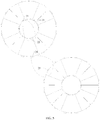
- FIG. 5 a cross-sectional view of two cabinet servers performing radio signal transmission is shown in FIG. 5 .
- a second intra-group communications element 22 receiving a radio signal transmits the radio signal to a second inter-group communications element 24 corresponding to the processing module, and the second inter-group communications element 24 transmits the radio signal to a processing module of another cabinet server in a form of an electromagnetic energy beam.
- a third inter-group communications element 25 disposed at the processing module of the another cabinet server receives the radio signal, so as to implement radio signal inter-group transmission.
- the radio signal when a radio signal is transmitted by using a wireless data center, the radio signal generates electromagnetic radiation, the radio signal is horizontally transmitted in a processing module in a form of an electromagnetic energy beam, and the electromagnetic radiation generated by the radio signal causes electromagnetic interference to an electronic device in the processing module, thereby affecting a service life of the electronic device and transmission quality of the radio signal.
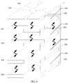
- FIG. 6 is a front view of an architecture of a cabinet server disclosed in this application.
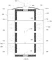
- FIG. 7 is a side view of a structure of a cabinet server disclosed in this application.
- the cabinet server includes at least two function nodes 100, multiple intra-cabinet antennas 200, and multiple inter-cabinet antennas 300.
- the function nodes 100 are vertically arranged, to form a server core, where the server core includes multiple function node layers, and each function node layer includes at least one function node 100.
- a solution in which the server core is decoupled into multiple function nodes 100 is used, so that a user decouples the server core into needed function nodes according to an application requirement, thereby implementing maximization of flexible resource configuration.
- the server core may be decoupled into multiple different function nodes.
- a computing node, a memory node, a storage node, and an I/O (Input/Output, input/output) node may be configured in the server core.
- radio signals received and sent by different function nodes are varied.
- the computing node, the memory node, the storage node, and the I/O node are configured in the server core
- radio signals received and sent by the function nodes are correspondingly computing request data, memory data, storage data, and I/O data.
- the function nodes may include one or more processing modules in the prior art.
- the intra-cabinet antennas 200 are vertically arranged and are disposed at a side of the server core, an intra-cabinet antenna 200 corresponding to each function node 100 has a frequency needed by the corresponding function node 100, the intra-cabinet antenna 200 and the corresponding function node 100 are electrically connected, and adjacent intra-cabinet antennas 200 are wirelessly connected.
- the adjacent intra-cabinet antennas 200 are wirelessly connected, so that a radio signal is transmitted between intra-cabinet antennas that are vertically adjacent.
- the intra-cabinet antenna 200 may be connected to the function node 100 in a one-to-one correspondence.
- the intra-cabinet antenna 200 that is in a one-to-one correspondence with the function node 100 has a frequency needed by the function node 100.
- the two or more function nodes may be connected to the intra-cabinet antenna having multiple needed frequencies.
- the intra-cabinet antenna transmits a radio signal in a frequency division multiplexing manner.
- each intra-cabinet antenna 200 is configured to transmit, after receiving the radio signal, the radio signal to a vertically adjacent intra-cabinet antenna 200, until the radio signal is transmitted to a target intra-cabinet antenna of the multiple intra-cabinet antennas 200, and the target intra-cabinet antenna transmits the radio signal to a function node 100 that is electrically connected to the target intra-cabinet antenna, so that the function node 100 analyzes and processes the radio signal.
- the intra-cabinet antenna 200 When the radio signal is transmitted within the cabinet server, if the intra-cabinet antenna 200 obtains the radio signal, the intra-cabinet antenna 200 transmits the radio signal to the function node 100 connected to the intra-cabinet antenna 200, and the function node 100 determines whether the radio signal is data needed by the function node 100; and if not, the function node 100 transmits the radio signal to an intra-cabinet antenna 200 connected to the function node 100, and the connected intra-cabinet antenna 200 transmits the radio signal to an intra-cabinet antenna 200 that is vertically adjacent to the connected intra-cabinet antenna 200; or if yes, the function node 100 analyzes and processes the radio signal.
- An embodiment of the present invention discloses a cabinet server.
- the cabinet server includes at least two function nodes, multiple intra-cabinet antennas, and multiple inter-cabinet antennas.
- the function nodes are vertically arranged, to form a server core, where the server core includes multiple function node layers, and each function node layer includes at least one function node.
- the intra-cabinet antennas are vertically arranged, disposed at a side of the server core, and electrically connected to corresponding function nodes, and adjacent intra-cabinet antennas are wirelessly connected.
- an intra-cabinet antenna in the cabinet server transmits the radio signal to a vertically adjacent intra-cabinet antenna, so as to implement transmission of the radio signal between adjacent intra-cabinet antennas.
- a transmission path of the radio signal is formed of vertically arranged intra-cabinet antennas.
- the cabinet server further includes a wireless data controller 400.
- the wireless data controller 400 is disposed outside the server core and is connected to an intra-cabinet antenna 200 disposed at a top layer and an inter-cabinet antenna 300.
- the wireless data controller 400 is generally disposed at a top of the server core. In addition, the wireless data controller 400 may be further disposed at the side of the server core. There is generally one wireless data controller 400, or there may be multiple wireless data controllers 400. When there are multiple wireless data controllers 400, the multiple wireless data controllers 400 are separately connected to different intra-cabinet antennas disposed at the top layer.
- Each inter-cabinet antenna 300 is disposed at the top of the server core.
- the intra-cabinet antenna 200 disposed at the top layer transmits the radio signal to the wireless data controller 400, and the wireless data controller 400 transmits the radio signal to the connected inter-cabinet antenna 300.
- the inter-cabinet antenna 300 is configured to receive the radio signal transmitted by the wireless data controller 400 and transmit the radio signal to the another cabinet server; and receive a radio signal transmitted by another cabinet server, and transmit, to the wireless data controller 400 connected to the inter-cabinet antenna 300, the radio signal transmitted by the another cabinet server, so that the wireless data controller 400 transmits, to the intra-cabinet antenna 200 at the top layer, the radio signal transmitted by the another cabinet server.
- the wireless data controller 400 is configured to: after receiving a to-be-transmitted radio signal, control the inter-cabinet antenna 300 to transmit the radio signal to another cabinet server, or after receiving a radio signal transmitted by another cabinet server, the wireless data controller 400 controls an inter-cabinet antenna 300 to transmit the radio signal to an intra-cabinet antenna 200 disposed at the top, so that the intra-cabinet antenna 200 transmits a radio signal within the cabinet server.
- the wireless data controller 400 transmits the data by using a corresponding scheduling strategy according to a data feature of the received radio signal. For example, when the wireless data controller 400 obtains a radio signal, the wireless data controller 400 performs an analysis according to a data feature of the radio signal; and when the radio signal needs to be transmitted between the cabinet server and another cabinet server, the wireless data controller 400 transmits the radio signal to the inter-cabinet antenna 300 and controls the inter-cabinet antenna 300 to transmit the radio signal to the another cabinet server; or when the radio signal needs to be transmitted within the cabinet server, the inter-cabinet antenna 300 transmits the radio signal to an intra-cabinet antenna 200, and transmission of the radio signal within the cabinet server is implemented by using the intra-cabinet antenna 200.
- the inter-cabinet antenna 300 is generally disposed at a top of the cabinet server. In addition, the inter-cabinet antenna 300 may be further disposed at two sides of the cabinet server.
- an intra-cabinet antenna disposed at a top layer, a wireless data controller, and inter-cabinet antennas form a transmission path, and the radio signal does not pass through function nodes, thereby reducing an effect of electromagnetic radiation generated by the radio signal on various electronic devices in the function nodes, improving service lives of the electronic devices, and improving transmission quality of the radio signal.
- the cabinet server further includes a wireless shield layer 500.
- the wireless shield layer 500 wraps the outside of the server core; and the intra-cabinet antennas 200, the inter-cabinet antennas 300, and the wireless data controller 400 are disposed outside the wireless shield layer 500.
- the wireless shield layer 500 is generally made of a metal material.
- the intra-cabinet antennas 200, the inter-cabinet antennas 300, and the wireless data controller 400 are all disposed outside the wireless shield layer 500, and the server core including the function nodes 100 is disposed inside the wireless shield layer 500; therefore, when a radio signal is transmitted, the wireless shield layer can shield the electromagnetic radiation generated by the radio signal, thereby avoiding the effect of the electromagnetic radiation on various electronic devices in the server core, and further improving service lives of the electronic devices and transmission quality of the radio signal.
- the cabinet server disclosed in this application further includes an antenna backplane 600.
- the antenna backplane 600 is disposed outside the wireless shield layer 500 and configured to fasten the intra-cabinet antenna 200.
- the antenna backplane 600 is generally disposed between the wireless shield layer 500 and a housing of the cabinet server.
- the intra-cabinet antenna 200 can be fastened by using the antenna backplane, and the antenna backplane 600 is generally made of a metal material, which not only can prevent leakage of a radio signal, but also can isolate radiation generated by a radio signal in another cabinet server.
- the intra-cabinet antenna 200 can be further fastened in another form, for example, by using an internal fastening method.
- the cabinet server further includes an extension plate.
- the extension plate is disposed outside the wireless shield layer, is disposed in parallel with the function nodes, and is configured to fasten the intra-cabinet antenna.
- the extension plate may be a protruding structure disposed on the wireless shield layer 500, or an extension portion of the function node 100, and the wireless shield layer 500 is disposed between the function node 100 and the extension portion.
- a hollow cavity is formed between adjacent function nodes 100, and the hollow cavity may be referred to as a node cavity 700.
- Setting of the node cavity 700 helps the function node 100 perform heat dissipation, thereby improving a service life of the cabinet server.
- an antenna cavity 800 is correspondingly formed between intra-cabinet antennas 200 correspondingly connected to the function nodes. Existence of the antenna cavity 800 helps improve heat sink performance of the cabinet server.
- the intra-cabinet antenna 200 is connected to a corresponding function node 100 by using a microstrip.
- the function nodes include a computing node and a memory node
- the function nodes include a computing node and a memory node
- Multiple processors are disposed in the computing node, and are connected to corresponding intra-cabinet antennas 200 by using microstrips 900.
- a memory pool controller and multiple memory modules connected to the memory pool controller are disposed inside the memory node, and the memory pool controller and the multiple memory modules are connected to corresponding intra-cabinet antennas 200 by using microstrips 900.
- the microstrip has advantages of a small volume, being lightweight, use of a wide frequency band, high reliability, and low manufacturing costs, and can carry radio signals of different frequencies. Use of the microstrip helps the function node transmit a radio signal in a wireless frequency division multiplexing manner, thereby implementing path sharing and improving transmission efficiency. Refer to a schematic diagram of radio signal transmission shown in FIG. 11 .
- a first function node determines whether an obtained radio signal is needed by the first function node by using a method for address segment parsing and routing table query; and if yes, the first function node analyzes and processes the obtained radio signal; or if not, the first function node transmits the obtained radio signal to an intra-cabinet antenna connected to the first function node, the intra-cabinet antenna correspondingly connected to the first function node transmits the radio signal to a vertically adjacent intra-cabinet antenna, after receiving the radio signal, the vertically adjacent intra-cabinet antenna transmits the radio signal to a second function node correspondingly connected to the vertically adjacent intra-cabinet antenna, and the second function node correspondingly connected to the vertically adjacent intra-cabinet antenna determines whether the radio signal is needed by the second function node.
- an intra-cabinet antenna correspondingly connected to the function node at the top layer transmits the radio signal to a wireless data controller.
- the inter-cabinet antennas receive the radio signal transmitted by the wireless data controller, and transmit the radio signal to another cabinet server under control of the wireless data controller.
- a wireless data controller of the another cabinet server determines whether the radio signal is needed by the wireless data controller; and if not, the wireless data controller continues to transmit the radio signal to another cabinet server; or if yes, after receiving the radio signal, the another cabinet server transmits, by using an intra-cabinet antenna, the radio signal to a function node corresponding to the radio signal.
- the I/O node when function nodes disposed in the server core from a bottom layer to a top layer are sequentially an I/O node, a storage node, a memory node, and a computing node, when the I/O node obtains a radio signal and knows by means of determining that the radio signal is not I/O data needed by the I/O node, the I/O node transmits the radio signal to a first intra-cabinet antenna connected to the I/O node.
- the first intra-cabinet antenna transmits the radio signal to a second intra-cabinet antenna correspondingly connected to the storage node, and then the second intra-cabinet antenna transmits the radio signal to the storage node.
- the storage node determines whether the radio signal is storage data needed by the storage node; and if yes, the storage node analyzes and processes the radio signal; or if not, the storage node transmits the radio signal to the second intra-cabinet antenna connected to the storage node.
- the second intra-cabinet antenna transmits the radio signal to a third intra-cabinet antenna correspondingly connected to the memory node.
- the third intra-cabinet antenna transmits the received radio signal to the memory node.
- the memory node determines whether the radio signal is memory data needed by the memory node, and if yes, the memory node analyzes and processes the radio signal; or if not, the memory node transmits the radio signal to a third inter-cabinet antenna, the third intra-cabinet antenna transmits the radio signal to a fourth intra-cabinet antenna connected to the computing node, and the fourth intra-cabinet antenna transmits the radio signal to the computing node.
- the computing node determines whether the radio signal is computing request data needed by the computing node; and if yes, the computing node parses and uses the radio signal; or if not, the computing node transmits the radio signal to the fourth intra-cabinet antenna.
- the fourth intra-cabinet antenna transmits the radio signal to a wireless data controller.
- the wireless data controller transmits the radio signal to an inter-cabinet antenna connected to the wireless data controller.
- the inter-cabinet antenna transmits the radio signal to another cabinet server.
- the wireless data controller receives a radio signal transmitted by an intra-cabinet antenna disposed at a top layer and places the radio signal into a data packet buffer module.
- the data packet buffer module transmits the radio signal to a data classification statistics module.
- the data classification statistics module classifies the radio signal according to a data feature of the radio signal and saves the radio signal into a corresponding queue.
- the radio signal may be saved into a processor request queue, a memory data packet queue, a storage data packet queue, or an I/O packet queue according to the data feature of the radio signal.
- the data classification statistics module transmits the classified radio signal to a priority scheduling module, and the priority scheduling module obtains a scheduling strategy preset in a scheduling strategy setting module and then transmits the radio signal to a channel configuration module; then the channel configuration module transmits the radio signal to a transceiver; the transceiver transmits the radio signal to a transmit antenna switch; then the transmit antenna switch transmits the radio signal to a corresponding inter-cabinet antenna; and then, the inter-cabinet antenna transmits the radio signal to a corresponding cabinet server.
- a transmission path is formed of intra-cabinet antennas that are vertically adjacent to each other. All of the intra-cabinet antennas are connected to function nodes corresponding to the intra-cabinet antennas. Multiple layers of function nodes are generally included in the server core, and the multiple layers of function nodes and the intra-cabinet antennas are vertically arranged, thereby implementing vertical transmission of a radio signal.
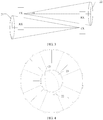
- a first intra-group communications element 21 when a wireless data center disclosed in the prior art performs radio signal intra-group transmission, a first intra-group communications element 21 generally transmits a radio signal to a second intra-group communications element in a form of an electromagnetic energy beam.
- An angle between the electromagnetic energy beam and a horizontal direction is ⁇ , which is used to represent a transverse diffusion range of the electromagnetic energy beam.
- the electromagnetic energy beam encounters overlapping of radiation fields, which causes a transmission conflict.
- the degree of the angle ⁇ needs to be controlled. Therefore, a radio signal needs to be transmitted by using a narrow lobe.
- the cabinet server further includes a bottom inter-cabinet antenna disposed at a bottom of the server core; and a bottom wireless data controller that is disposed at the bottom of the server core and that is connected to the bottom inter-cabinet antenna, where the bottom wireless data controller is connected to a function node at a bottom layer.
- the bottom wireless data controller is configured to: after receiving a radio signal transmitted by the function node at the bottom layer, transmit the radio signal to the bottom inter-cabinet antenna, so that the bottom inter-cabinet antenna transmit the radio signal to another cabinet server; and after receiving a radio signal transmitted by the bottom inter-cabinet antenna, transmit the radio signal to the bottom inter-cabinet antenna.
- FIG. 11 a schematic diagram of radio signal transmission shown in FIG. 11 .
- the radio signal needs to be sequentially transmitted by all layers of intra-cabinet antennas, so as to transmit the radio signal to an intra-cabinet antenna corresponding to a function node at a top layer. Then, the intra-cabinet antenna corresponding to the function node at the top layer transmits the radio signal to another cabinet server.
- the function node at the bottom layer may transmit the radio signal to the bottom wireless data controller by using an intra-cabinet antenna connected to the function node.
- the bottom inter-cabinet antenna transmits the radio signal to the another cabinet server without a need of a process in which the radio signal is transmitted by using multiple layers of intra-cabinet antennas, which further shortens a transmission path of the radio signal, reduces a transmission delay, and improves a transmission speed of the radio signal.
- the cabinet server includes at least two function nodes 100, multiple intra-cabinet antennas 200, multiple inter-cabinet antennas 300, and a wireless data controller 400. Moreover, the cabinet server further includes rack top antennas 110.
- the rack top antennas 110 are disposed above the intra-cabinet antenna disposed at the top layer, where the rack top antennas 110 and the intra-cabinet antennas 200 are vertically arranged, the rack top antennas 110 and the intra-cabinet antennas at the top layer are wirelessly connected, and the rack top antennas 110 and the wireless data controller 400 are connected.
- the rack top antenna 110 is configured to receive a radio signal transmitted by the intra-cabinet antenna 200 at the top layer and transmit the radio signal to the wireless data controller 400; and receive a radio signal transmitted by the wireless data controller 400 and then transmit the radio signal to the intra-cabinet antenna 200 at the top layer.
- the intra-cabinet antenna 200 disposed at the top layer and the rack top antenna 110 are generally connected in a wireless connection form.
- the rack top antenna 110 is generally connected to the wireless data controller 400 in a wired form. If no rack top antenna 110 is disposed in the cabinet server, the intra-cabinet antennas 200 disposed at the top layer are directly connected to the wireless data controller 400.
- the intra-cabinet antenna 200 at the top layer transmits the radio signal to the connected wireless data controller 400, and the wireless data controller 400 controls the inter-cabinet antenna 300 to transmit the radio signal to the another cabinet server.
- the inter-cabinet antenna 300 transmits the radio signal to the intra-cabinet antenna 200 at the top layer by using the wireless data controller 400, and the intra-cabinet antenna 200 at the top layer transmits the radio signal within the cabinet server.
- the rack top antennas 110 are disposed in the cabinet server, the rack top antennas 110 are connected to the wireless data controller 400, and the rack top antennas 110 are used as a radio signal transmission medium between the intra-cabinet antennas 200 at the top layer and the wireless data controller 400.
- the wireless data controller 400 transmits the radio signal to the intra-cabinet antenna at the top layer by using the rack top antenna 110, or the intra-cabinet antenna at the top layer transmits the radio signal to the wireless data controller 400 by using the rack top antenna 110.
- a radio signal transmission medium is added, which facilitates improvement of radio signal transmission quality.
- the data center includes the cabinet server described above.
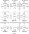
- the data center includes multiple cabinet servers, where the cabinet servers implement radio signal inter-cabinet transmission by using a wireless connection formed by inter-cabinet antennas.
- the cabinet servers implement radio signal inter-cabinet transmission by using a wireless connection formed by inter-cabinet antennas.
- a transmission path from the No. 6 cabinet server to a No. 7 cabinet server to a No. 8 cabinet server to a No. 5 cabinet server to the No. 2 cabinet server may be made according to a current occupied degree of each cabinet server.
- another transmission path may be further made, which is not limited in this application.
- a housing of the cabinet server may be set to have multiple shapes.
- the housing is set to be square. Relative to a structure in another shape, a square structure has a relatively large available volume, and more devices can be deployed in the square structure.
- the multiple cabinet servers are generally formed into a form of a square matrix, which facilitates radio signal transmission.
- used inter-cabinet antennas are generally directional antennas.
- Directional antennas in a same direction form an antenna array.
- a radio signal is transmitted by using the directional antennas, a signal strength can be enhanced and an anti-interference capability can be improved.
- the technologies in the embodiments of the present invention may be implemented by software in addition to a necessary general hardware platform.
- the technical solutions of the present invention essentially or the part contributing to the prior art may be implemented in a form of a software product.
- the software product is stored in a storage medium, such as a ROM/RAM, a hard disk, or an optical disc, and includes several instructions for instructing a computer device (which may be a personal computer, a server, or a network device) to perform the methods described in the embodiments or some parts of the embodiments of the present invention.
Landscapes
- Engineering & Computer Science (AREA)
- General Engineering & Computer Science (AREA)
- Theoretical Computer Science (AREA)
- Computer Hardware Design (AREA)
- Physics & Mathematics (AREA)
- General Physics & Mathematics (AREA)
- Computer Networks & Wireless Communication (AREA)
- Microelectronics & Electronic Packaging (AREA)
- Signal Processing (AREA)
- Mobile Radio Communication Systems (AREA)
- Radio Transmission System (AREA)
Claims (10)
- Schrank-Server, wobei der Schrank-Server wenigstens zwei Funktionsknoten (100), mehrere schrankinterne Antennen (200) und mehrere Zwischenschrankantennen (300) umfasst, wobei
die Funktionsknoten (100) vertikal angeordnet sind, um einen Server-Kern zu bilden, wobei der Server-Kern mehrere Funktionsknotenschichten umfasst und jede Funktionsknotenschicht wenigstens einen Funktionsknoten (100) umfasst;
die schrankinternen Antennen (200) vertikal angeordnet sind und auf einer Seite des Server-Kerns angeordnet sind, wobei eine schrankinterne Antenne (200), die jedem Funktionsknoten (100) entspricht, eine Frequenz aufweist, die durch den entsprechenden Funktionsknoten (100) benötigt wird, die schrankinterne Antenne (200) und der entsprechende Funktionsknoten (100) elektrisch verbunden sind und benachbarte schrankinterne Antennen (200) drahtlos verbunden sind; und
jede schrankinterne Antenne (200) dann, wenn ein Funksignal innerhalb des Schrank-Servers gesendet wird, konfiguriert ist, nach dem Empfangen des Funksignals das Funksignal an eine vertikal benachbarte schrankinterne Antenne (200) zu senden, bis das Funksignal an eine schrankinterne Zielantenne (200) der mehreren schrankinternen Antennen (200) gesendet wird, wobei die schrankinterne Zielantenne (200) das Funksignal an einen Funktionsknoten (100) sendet, der mit der schrankinternen Zielantenne (200) elektrisch verbunden ist, so dass der Funktionsknoten (100) das Funksignal analysiert und verarbeitet, und
wobei ein hohler Hohlraum (700) zwischen benachbarten Funktionsknoten (100) ausgebildet ist und
das Funksignal in Form einer breiten Strahlungskeule gesendet wird. - Schrank-Server nach Anspruch 1, wobei der Schrank-Server ferner einen drahtlosen Daten-Controller (400) umfasst und der drahtlose Daten-Controller (400) außerhalb des Server-Kerns angeordnet ist und mit einer schrankinternen Antenne (200), die in einer oberen Schicht angeordnet ist, und einer Zwischenschrankantenne (300) verbunden ist;
jede Zwischenschrankantenne (300) an einem Oberteil des Server-Kerns angeordnet ist;
wenn das Funksignal zwischen dem Schrank-Server und einem weiteren Schrank-Server gesendet wird, die schrankinterne Antenne (200), die in einer oberen Schicht angeordnet ist, nach dem Erhalten des Funksignals das Funksignal an den drahtlosen Daten-Controller (400) sendet und der drahtlose Daten-Controller (400) das Funksignal an die angeschlossene Zwischenschrankantenne (300) sendet; und
die Zwischenschrankantenne (300) konfiguriert ist, das durch den drahtlosen Daten-Controller (400) gesendete Funksignal zu empfangen und das Funksignal an den weiteren Schrank-Server zu senden; und ein durch den weiteren Schrank-Server gesendetes Funksignal zu empfangen und das durch den weiteren Schrank-Server gesendete Funksignal an den drahtlosen Daten-Controller (400), der mit der Zwischenschrankantenne (400) verbunden ist, zu senden, so dass der drahtlose Daten-Controller (400) das durch den weiteren Schrank-Server gesendete Funksignal an die schrankinterne Antenne (200) in der oberen Schicht sendet. - Schrank-Server nach Anspruch 2, wobei der Schrank-Server ferner Folgendes umfasst:eine drahtlose Abschirmschicht (500), wobei die drahtlose Abschirmschicht das Äußere des Server-Kerns umhüllt; unddie schrankinternen Antennen (200), die Zwischenschrankantennen (300) und der drahtlose Daten-Controller (400) außerhalb der drahtlosen Abschirmschicht (500) angeordnet sind.
- Schrank-Server nach Anspruch 3, wobei der Schrank-Server ferner Folgendes umfasst:
eine Antennenrückplatte (600), wobei die Antennenrückplatte (600) außerhalb der drahtlosen Abschirmschicht (500) angeordnet ist und konfiguriert ist, die schrankinterne Antenne (200) zu befestigen. - Schrank-Server nach Anspruch 3, wobei der Schrank-Server ferner Folgendes umfasst:
eine Erweiterungsplatte, wobei die Erweiterungsplatte außerhalb der drahtlosen Abschirmschicht (500) angeordnet ist, zu den Funktionsknoten (100) parallel angeordnet ist und konfiguriert ist, die schrankinterne Antenne (200) zu befestigen. - Schrank-Server nach Anspruch 1, wobei die Funktionsknoten (100) Folgendes umfassen:
einen Rechenknoten, einen Datenspeicherknoten, einen Speicherknoten und einen Eingabe-/Ausgabeknoten. - Schrank-Server nach Anspruch 2, wobei der Schrank-Server ferner Folgendes umfasst:eine untere Zwischenschrankantenne, die an einem Boden des Server-Kerns angeordnet ist; undeinen unteren drahtlosen Daten-Controller, der am Boden des Server-Kerns angeordnet ist und der mit der unteren Zwischenschrankantenne verbunden ist, wobei der untere drahtlose Daten-Controller mit einem Funktionsknoten in einer unteren Schicht verbunden ist; undder untere drahtlose Daten-Controller konfiguriert ist: nach dem Empfangen eines durch den Funktionsknoten in der unteren Schicht gesendeten Funksignals das Funksignal an die untere Zwischenschrankantenne zu senden, so dass die untere Zwischenschrankantenne das Funksignal an einen weiteren Schrank-Server sendet; und nach dem Empfangen eines durch die untere Zwischenschrankantenne gesendeten Funksignals das Funksignal an den Funktionsknoten in der unteren Schicht zu senden.
- Schrank-Server nach einem der Ansprüche 2 bis 7, wobei der Schrank-Server ferner Folgendes umfasst:obere Gestellantennen (110), die über der schrankinternen Antenne (200), die in der oberen Schicht angeordnet ist, angeordnet sind, wobei die oberen Gestellantennen (110) und die schrankinternen Antennen (200) vertikal angeordnet sind, die oberen Gestellantennen (110) und die schrankinternen Antennen (200) in der oberen Schicht drahtlos verbunden sind und die oberen Gestellantennen (110) und der drahtlose Daten-Controller (400 verbunden sind; unddie obere Gestellantenne (110) konfiguriert ist, ein durch die schrankinterne Antenne (200) in der oberen Schicht gesendetes Funksignal zu empfangen und das Funksignal an den drahtlosen Daten-Controller (400) zu senden; und ein durch den drahtlosen Daten-Controller (400) gesendetes Funksignal zu empfangen und dann das Funksignal an die schrankinterne Antenne (200) in der oberen Schicht zu senden.
- Datenzentrum, wobei das Datenzentrum Folgendes umfasst:
den Schrank-Server nach einem der Ansprüche 1 bis 8. - Datenzentrum nach Anspruch 9, wobei
in dem Datenzentrum benachbarte Schrank-Server unter Verwendung einer Zwischenschrankantenne (300) drahtlos verbunden sind.
Applications Claiming Priority (1)
| Application Number | Priority Date | Filing Date | Title |
|---|---|---|---|
| PCT/CN2014/077670 WO2015172381A1 (zh) | 2014-05-16 | 2014-05-16 | 柜式服务器及基于所述柜式服务器的数据中心 |
Publications (3)
| Publication Number | Publication Date |
|---|---|
| EP3089043A1 EP3089043A1 (de) | 2016-11-02 |
| EP3089043A4 EP3089043A4 (de) | 2017-03-22 |
| EP3089043B1 true EP3089043B1 (de) | 2020-12-30 |
Family
ID=54479199
Family Applications (1)
| Application Number | Title | Priority Date | Filing Date |
|---|---|---|---|
| EP14891927.7A Active EP3089043B1 (de) | 2014-05-16 | 2014-05-16 | Schrankserver sowie darauf basierendes datencenter |
Country Status (9)
| Country | Link |
|---|---|
| US (1) | US10069189B2 (de) |
| EP (1) | EP3089043B1 (de) |
| JP (1) | JP6335320B2 (de) |
| KR (1) | KR101933903B1 (de) |
| CN (1) | CN105308583B (de) |
| BR (1) | BR112016019409B1 (de) |
| RU (1) | RU2642809C1 (de) |
| SG (1) | SG11201606112VA (de) |
| WO (1) | WO2015172381A1 (de) |
Families Citing this family (7)
| Publication number | Priority date | Publication date | Assignee | Title |
|---|---|---|---|---|
| US20170300807A1 (en) * | 2016-02-22 | 2017-10-19 | Aivitae LLC | Neural net computer system with wireless or optical connections between neural net computing nodes |
| JP6746051B2 (ja) * | 2016-03-30 | 2020-08-26 | 株式会社国際電気通信基礎技術研究所 | 電子機器の収容構造体 |
| EP3696989B1 (de) * | 2017-11-20 | 2021-09-22 | Huawei Technologies Co., Ltd. | Signalübertragungsvorrichtung und -system |
| US10587997B2 (en) * | 2017-12-01 | 2020-03-10 | At&T Intellectual Property I, L.P. | Facilitating wireless machine to machine communication solutions in 5G or other next generation networks |
| CN109309633B (zh) * | 2018-09-21 | 2021-06-15 | 郑州云海信息技术有限公司 | 一种基于管理交换机的整机柜服务器节点管理方法及装置 |
| CN110417590A (zh) * | 2019-07-23 | 2019-11-05 | 浪潮电子信息产业股份有限公司 | 服务器配置方法、装置、整机柜服务器及可读存储介质 |
| CN115643712B (zh) * | 2022-09-26 | 2024-12-17 | 超聚变数字技术有限公司 | 机柜服务器及机柜服务器的控制方法 |
Citations (1)
| Publication number | Priority date | Publication date | Assignee | Title |
|---|---|---|---|---|
| US20110243074A1 (en) * | 2010-04-05 | 2011-10-06 | Microsoft Corporation | Data Center Using Wireless Communication |
Family Cites Families (24)
| Publication number | Priority date | Publication date | Assignee | Title |
|---|---|---|---|---|
| US5754948A (en) * | 1995-12-29 | 1998-05-19 | University Of North Carolina At Charlotte | Millimeter-wave wireless interconnection of electronic components |
| US6882867B1 (en) * | 2001-03-30 | 2005-04-19 | Bellsouth Intellectual Property Corporation | Extra capacity radio base station for wireless communication |
| JP4282913B2 (ja) | 2001-05-11 | 2009-06-24 | 株式会社無限 | サーバラック |
| US20040166905A1 (en) * | 2003-02-07 | 2004-08-26 | Hewlett-Packard Development Company, L.P. | Radio frequency linked computer architecture |
| US8526881B2 (en) * | 2005-04-18 | 2013-09-03 | The Boeing Company | Mechanically isolated wireless communications system and method |
| US20060273962A1 (en) * | 2005-06-02 | 2006-12-07 | Brench Colin E | Rack mounted directional antenna |
| US7648065B2 (en) * | 2005-08-31 | 2010-01-19 | The Stanley Works | Storage cabinet with improved RFID antenna system |
| US20080114865A1 (en) * | 2006-11-14 | 2008-05-15 | Rothman Michael A | Methods and apparatus to manage computing platforms |
| US8897184B2 (en) * | 2007-06-22 | 2014-11-25 | Vubiq Networks, Inc. | System and method for wireless communication in a backplane fabric architecture |
| US8873426B2 (en) | 2008-07-10 | 2014-10-28 | Nec Laboratories America, Inc. | Wireless network connectivity in data centers |
| US8264354B2 (en) * | 2009-10-14 | 2012-09-11 | Attend Systems, Llc | Data center equipment location and monitoring system |
| US20110164880A1 (en) | 2010-01-06 | 2011-07-07 | Searete Llc, A Limited Liability Corporation Of The State Of Delaware | Data center with free-space optical communications |
| US8907878B2 (en) | 2010-04-14 | 2014-12-09 | Sharp Kabushiki Kaisha | Liquid crystal display device and method for displaying fonts on liquid crystal display device |
| US8362878B2 (en) * | 2010-06-14 | 2013-01-29 | R.E.D. Stamp, Inc. | Towel tracking system |
| US20120311127A1 (en) | 2011-05-31 | 2012-12-06 | Microsoft Corporation | Flyway Generation in Data Centers |
| US9537794B2 (en) * | 2011-07-29 | 2017-01-03 | Vubiq Networks, Inc. | System and method for wireless communication in a backplane fabric architecture |
| CN102436610B (zh) * | 2011-12-13 | 2015-11-18 | 上海互惠信息技术有限公司 | 一种基于射频识别的数据中心智能管理系统和方法 |
| CN102857291B (zh) | 2012-01-04 | 2015-01-07 | 东南大学 | 一种基于均匀天线阵的提高无线传输接收信号增益方法 |
| US9225442B2 (en) * | 2012-02-21 | 2015-12-29 | Avaya Inc. | Managing antennas on an access point in a wireless network |
| CN103777734A (zh) * | 2012-10-25 | 2014-05-07 | 英业达科技有限公司 | 机柜式服务器系统与其操作方法 |
| CN203133891U (zh) * | 2012-11-27 | 2013-08-14 | 上海质尊溯源电子科技有限公司 | 一种uhf rfid的智能密集柜 |
| CN103179517B (zh) | 2013-02-01 | 2015-08-19 | 清华大学 | 一种数据中心的无线组播方法 |
| CN203276314U (zh) * | 2013-04-07 | 2013-11-06 | 赵海峰 | 一种基于rfid技术的刀片服务器定位装置 |
| RU131556U1 (ru) * | 2013-04-30 | 2013-08-20 | Общество с ограниченной ответственностью "ДЕПО Электроникс" | Стойка для аппаратуры вычислительной техники |
-
2014
- 2014-05-16 EP EP14891927.7A patent/EP3089043B1/de active Active
- 2014-05-16 RU RU2016137716A patent/RU2642809C1/ru active
- 2014-05-16 SG SG11201606112VA patent/SG11201606112VA/en unknown
- 2014-05-16 JP JP2016553851A patent/JP6335320B2/ja active Active
- 2014-05-16 CN CN201480033040.4A patent/CN105308583B/zh active Active
- 2014-05-16 WO PCT/CN2014/077670 patent/WO2015172381A1/zh not_active Ceased
- 2014-05-16 BR BR112016019409-8A patent/BR112016019409B1/pt active IP Right Grant
- 2014-05-16 KR KR1020167022724A patent/KR101933903B1/ko active Active
-
2016
- 2016-09-26 US US15/276,207 patent/US10069189B2/en active Active
Patent Citations (1)
| Publication number | Priority date | Publication date | Assignee | Title |
|---|---|---|---|---|
| US20110243074A1 (en) * | 2010-04-05 | 2011-10-06 | Microsoft Corporation | Data Center Using Wireless Communication |
Also Published As
| Publication number | Publication date |
|---|---|
| US10069189B2 (en) | 2018-09-04 |
| JP6335320B2 (ja) | 2018-05-30 |
| BR112016019409B1 (pt) | 2023-02-14 |
| EP3089043A4 (de) | 2017-03-22 |
| JP2017510888A (ja) | 2017-04-13 |
| EP3089043A1 (de) | 2016-11-02 |
| KR101933903B1 (ko) | 2018-12-31 |
| WO2015172381A1 (zh) | 2015-11-19 |
| RU2642809C1 (ru) | 2018-01-26 |
| BR112016019409A2 (pt) | 2018-05-08 |
| KR20160111478A (ko) | 2016-09-26 |
| CN105308583B (zh) | 2018-05-11 |
| SG11201606112VA (en) | 2016-08-30 |
| US20170012340A1 (en) | 2017-01-12 |
| CN105308583A (zh) | 2016-02-03 |
Similar Documents
| Publication | Publication Date | Title |
|---|---|---|
| US10069189B2 (en) | Cabinet server and data center based on cabinet server | |
| US12088394B2 (en) | Beam indication for multi-panel UE | |
| US8521095B2 (en) | System and method for intra-cabinet wireless communication | |
| KR101891448B1 (ko) | 중첩형과 스태거형 안테나 어레이 | |
| CN116530032B (zh) | 迭代传输细化 | |
| US12451602B2 (en) | Antenna system | |
| EP3888177B1 (de) | Hohlraumfilter und antennenmodul damit | |
| KR102928272B1 (ko) | 안테나 구조 및 이를 포함하는 전자 장치 | |
| CN116980914A (zh) | 波束管理的方法、通信装置以及通信系统 | |
| US20160344104A1 (en) | Antenna Structure | |
| US20250309538A1 (en) | Antenna device including radome and base station including antenna device | |
| WO2020216372A1 (zh) | 一种准八木天线阵列及毫米波基站设备 | |
| KR20140083692A (ko) | 무선 백홀 형성 장치와 무선 백홀 형성 시스템, 및 무선 백홀 형성 방법 | |
| JP7801328B2 (ja) | 二重偏波アンテナアレイを使用する通信 | |
| US10177445B1 (en) | Communication structure | |
| CN121620840A (zh) | 天线设备、天线阵列和天线系统 | |
| WO2025214328A1 (zh) | 波束控制方法、传输方法、装置、发送端及接收端 | |
| WO2025098171A1 (zh) | 通信方法和装置 | |
| TWM543515U (zh) | 通訊結構 |
Legal Events
| Date | Code | Title | Description |
|---|---|---|---|
| PUAI | Public reference made under article 153(3) epc to a published international application that has entered the european phase |
Free format text: ORIGINAL CODE: 0009012 |
|
| 17P | Request for examination filed |
Effective date: 20160729 |
|
| AK | Designated contracting states |
Kind code of ref document: A1 Designated state(s): AL AT BE BG CH CY CZ DE DK EE ES FI FR GB GR HR HU IE IS IT LI LT LU LV MC MK MT NL NO PL PT RO RS SE SI SK SM TR |
|
| AX | Request for extension of the european patent |
Extension state: BA ME |
|
| A4 | Supplementary search report drawn up and despatched |
Effective date: 20170216 |
|
| RIC1 | Information provided on ipc code assigned before grant |
Ipc: G06F 13/40 20060101ALI20170210BHEP Ipc: H04W 84/10 20090101ALI20170210BHEP Ipc: G06F 13/14 20060101AFI20170210BHEP Ipc: H01Q 1/22 20060101ALI20170210BHEP |
|
| DAX | Request for extension of the european patent (deleted) | ||
| STAA | Information on the status of an ep patent application or granted ep patent |
Free format text: STATUS: EXAMINATION IS IN PROGRESS |
|
| 17Q | First examination report despatched |
Effective date: 20190424 |
|
| GRAP | Despatch of communication of intention to grant a patent |
Free format text: ORIGINAL CODE: EPIDOSNIGR1 |
|
| STAA | Information on the status of an ep patent application or granted ep patent |
Free format text: STATUS: GRANT OF PATENT IS INTENDED |
|
| INTG | Intention to grant announced |
Effective date: 20200729 |
|
| INTG | Intention to grant announced |
Effective date: 20200804 |
|
| GRAS | Grant fee paid |
Free format text: ORIGINAL CODE: EPIDOSNIGR3 |
|
| GRAA | (expected) grant |
Free format text: ORIGINAL CODE: 0009210 |
|
| STAA | Information on the status of an ep patent application or granted ep patent |
Free format text: STATUS: THE PATENT HAS BEEN GRANTED |
|
| AK | Designated contracting states |
Kind code of ref document: B1 Designated state(s): AL AT BE BG CH CY CZ DE DK EE ES FI FR GB GR HR HU IE IS IT LI LT LU LV MC MK MT NL NO PL PT RO RS SE SI SK SM TR |
|
| REG | Reference to a national code |
Ref country code: GB Ref legal event code: FG4D |
|
| REG | Reference to a national code |
Ref country code: DE Ref legal event code: R096 Ref document number: 602014073897 Country of ref document: DE |
|
| REG | Reference to a national code |
Ref country code: AT Ref legal event code: REF Ref document number: 1350625 Country of ref document: AT Kind code of ref document: T Effective date: 20210115 |
|
| REG | Reference to a national code |
Ref country code: IE Ref legal event code: FG4D |
|
| PG25 | Lapsed in a contracting state [announced via postgrant information from national office to epo] |
Ref country code: NO Free format text: LAPSE BECAUSE OF FAILURE TO SUBMIT A TRANSLATION OF THE DESCRIPTION OR TO PAY THE FEE WITHIN THE PRESCRIBED TIME-LIMIT Effective date: 20210330 Ref country code: RS Free format text: LAPSE BECAUSE OF FAILURE TO SUBMIT A TRANSLATION OF THE DESCRIPTION OR TO PAY THE FEE WITHIN THE PRESCRIBED TIME-LIMIT Effective date: 20201230 Ref country code: FI Free format text: LAPSE BECAUSE OF FAILURE TO SUBMIT A TRANSLATION OF THE DESCRIPTION OR TO PAY THE FEE WITHIN THE PRESCRIBED TIME-LIMIT Effective date: 20201230 Ref country code: GR Free format text: LAPSE BECAUSE OF FAILURE TO SUBMIT A TRANSLATION OF THE DESCRIPTION OR TO PAY THE FEE WITHIN THE PRESCRIBED TIME-LIMIT Effective date: 20210331 |
|
| REG | Reference to a national code |
Ref country code: AT Ref legal event code: MK05 Ref document number: 1350625 Country of ref document: AT Kind code of ref document: T Effective date: 20201230 |
|
| PG25 | Lapsed in a contracting state [announced via postgrant information from national office to epo] |
Ref country code: BG Free format text: LAPSE BECAUSE OF FAILURE TO SUBMIT A TRANSLATION OF THE DESCRIPTION OR TO PAY THE FEE WITHIN THE PRESCRIBED TIME-LIMIT Effective date: 20210330 Ref country code: SE Free format text: LAPSE BECAUSE OF FAILURE TO SUBMIT A TRANSLATION OF THE DESCRIPTION OR TO PAY THE FEE WITHIN THE PRESCRIBED TIME-LIMIT Effective date: 20201230 Ref country code: LV Free format text: LAPSE BECAUSE OF FAILURE TO SUBMIT A TRANSLATION OF THE DESCRIPTION OR TO PAY THE FEE WITHIN THE PRESCRIBED TIME-LIMIT Effective date: 20201230 |
|
| REG | Reference to a national code |
Ref country code: NL Ref legal event code: MP Effective date: 20201230 |
|
| PG25 | Lapsed in a contracting state [announced via postgrant information from national office to epo] |
Ref country code: HR Free format text: LAPSE BECAUSE OF FAILURE TO SUBMIT A TRANSLATION OF THE DESCRIPTION OR TO PAY THE FEE WITHIN THE PRESCRIBED TIME-LIMIT Effective date: 20201230 |
|
| REG | Reference to a national code |
Ref country code: LT Ref legal event code: MG9D |
|
| PG25 | Lapsed in a contracting state [announced via postgrant information from national office to epo] |
Ref country code: LT Free format text: LAPSE BECAUSE OF FAILURE TO SUBMIT A TRANSLATION OF THE DESCRIPTION OR TO PAY THE FEE WITHIN THE PRESCRIBED TIME-LIMIT Effective date: 20201230 Ref country code: PT Free format text: LAPSE BECAUSE OF FAILURE TO SUBMIT A TRANSLATION OF THE DESCRIPTION OR TO PAY THE FEE WITHIN THE PRESCRIBED TIME-LIMIT Effective date: 20210430 Ref country code: SK Free format text: LAPSE BECAUSE OF FAILURE TO SUBMIT A TRANSLATION OF THE DESCRIPTION OR TO PAY THE FEE WITHIN THE PRESCRIBED TIME-LIMIT Effective date: 20201230 Ref country code: RO Free format text: LAPSE BECAUSE OF FAILURE TO SUBMIT A TRANSLATION OF THE DESCRIPTION OR TO PAY THE FEE WITHIN THE PRESCRIBED TIME-LIMIT Effective date: 20201230 Ref country code: CZ Free format text: LAPSE BECAUSE OF FAILURE TO SUBMIT A TRANSLATION OF THE DESCRIPTION OR TO PAY THE FEE WITHIN THE PRESCRIBED TIME-LIMIT Effective date: 20201230 Ref country code: EE Free format text: LAPSE BECAUSE OF FAILURE TO SUBMIT A TRANSLATION OF THE DESCRIPTION OR TO PAY THE FEE WITHIN THE PRESCRIBED TIME-LIMIT Effective date: 20201230 Ref country code: NL Free format text: LAPSE BECAUSE OF FAILURE TO SUBMIT A TRANSLATION OF THE DESCRIPTION OR TO PAY THE FEE WITHIN THE PRESCRIBED TIME-LIMIT Effective date: 20201230 |
|
| PG25 | Lapsed in a contracting state [announced via postgrant information from national office to epo] |
Ref country code: PL Free format text: LAPSE BECAUSE OF FAILURE TO SUBMIT A TRANSLATION OF THE DESCRIPTION OR TO PAY THE FEE WITHIN THE PRESCRIBED TIME-LIMIT Effective date: 20201230 Ref country code: AT Free format text: LAPSE BECAUSE OF FAILURE TO SUBMIT A TRANSLATION OF THE DESCRIPTION OR TO PAY THE FEE WITHIN THE PRESCRIBED TIME-LIMIT Effective date: 20201230 |
|
| PG25 | Lapsed in a contracting state [announced via postgrant information from national office to epo] |
Ref country code: IS Free format text: LAPSE BECAUSE OF FAILURE TO SUBMIT A TRANSLATION OF THE DESCRIPTION OR TO PAY THE FEE WITHIN THE PRESCRIBED TIME-LIMIT Effective date: 20210430 |
|
| REG | Reference to a national code |
Ref country code: DE Ref legal event code: R097 Ref document number: 602014073897 Country of ref document: DE |
|
| PG25 | Lapsed in a contracting state [announced via postgrant information from national office to epo] |
Ref country code: IT Free format text: LAPSE BECAUSE OF FAILURE TO SUBMIT A TRANSLATION OF THE DESCRIPTION OR TO PAY THE FEE WITHIN THE PRESCRIBED TIME-LIMIT Effective date: 20201230 Ref country code: AL Free format text: LAPSE BECAUSE OF FAILURE TO SUBMIT A TRANSLATION OF THE DESCRIPTION OR TO PAY THE FEE WITHIN THE PRESCRIBED TIME-LIMIT Effective date: 20201230 |
|
| PLBE | No opposition filed within time limit |
Free format text: ORIGINAL CODE: 0009261 |
|
| STAA | Information on the status of an ep patent application or granted ep patent |
Free format text: STATUS: NO OPPOSITION FILED WITHIN TIME LIMIT |
|
| PG25 | Lapsed in a contracting state [announced via postgrant information from national office to epo] |
Ref country code: ES Free format text: LAPSE BECAUSE OF FAILURE TO SUBMIT A TRANSLATION OF THE DESCRIPTION OR TO PAY THE FEE WITHIN THE PRESCRIBED TIME-LIMIT Effective date: 20201230 Ref country code: DK Free format text: LAPSE BECAUSE OF FAILURE TO SUBMIT A TRANSLATION OF THE DESCRIPTION OR TO PAY THE FEE WITHIN THE PRESCRIBED TIME-LIMIT Effective date: 20201230 |
|
| 26N | No opposition filed |
Effective date: 20211001 |
|
| REG | Reference to a national code |
Ref country code: CH Ref legal event code: PL |
|
| PG25 | Lapsed in a contracting state [announced via postgrant information from national office to epo] |
Ref country code: MC Free format text: LAPSE BECAUSE OF FAILURE TO SUBMIT A TRANSLATION OF THE DESCRIPTION OR TO PAY THE FEE WITHIN THE PRESCRIBED TIME-LIMIT Effective date: 20201230 Ref country code: LU Free format text: LAPSE BECAUSE OF NON-PAYMENT OF DUE FEES Effective date: 20210516 Ref country code: LI Free format text: LAPSE BECAUSE OF NON-PAYMENT OF DUE FEES Effective date: 20210531 Ref country code: CH Free format text: LAPSE BECAUSE OF NON-PAYMENT OF DUE FEES Effective date: 20210531 |
|
| REG | Reference to a national code |
Ref country code: BE Ref legal event code: MM Effective date: 20210531 |
|
| PG25 | Lapsed in a contracting state [announced via postgrant information from national office to epo] |
Ref country code: SI Free format text: LAPSE BECAUSE OF FAILURE TO SUBMIT A TRANSLATION OF THE DESCRIPTION OR TO PAY THE FEE WITHIN THE PRESCRIBED TIME-LIMIT Effective date: 20201230 |
|
| PG25 | Lapsed in a contracting state [announced via postgrant information from national office to epo] |
Ref country code: IE Free format text: LAPSE BECAUSE OF NON-PAYMENT OF DUE FEES Effective date: 20210516 |
|
| PG25 | Lapsed in a contracting state [announced via postgrant information from national office to epo] |
Ref country code: IS Free format text: LAPSE BECAUSE OF FAILURE TO SUBMIT A TRANSLATION OF THE DESCRIPTION OR TO PAY THE FEE WITHIN THE PRESCRIBED TIME-LIMIT Effective date: 20210430 |
|
| PG25 | Lapsed in a contracting state [announced via postgrant information from national office to epo] |
Ref country code: BE Free format text: LAPSE BECAUSE OF NON-PAYMENT OF DUE FEES Effective date: 20210531 |
|
| REG | Reference to a national code |
Ref country code: FR Ref legal event code: PLFP Year of fee payment: 10 |
|
| PG25 | Lapsed in a contracting state [announced via postgrant information from national office to epo] |
Ref country code: HU Free format text: LAPSE BECAUSE OF FAILURE TO SUBMIT A TRANSLATION OF THE DESCRIPTION OR TO PAY THE FEE WITHIN THE PRESCRIBED TIME-LIMIT; INVALID AB INITIO Effective date: 20140516 |
|
| PG25 | Lapsed in a contracting state [announced via postgrant information from national office to epo] |
Ref country code: CY Free format text: LAPSE BECAUSE OF FAILURE TO SUBMIT A TRANSLATION OF THE DESCRIPTION OR TO PAY THE FEE WITHIN THE PRESCRIBED TIME-LIMIT Effective date: 20201230 |
|
| PG25 | Lapsed in a contracting state [announced via postgrant information from national office to epo] |
Ref country code: SM Free format text: LAPSE BECAUSE OF FAILURE TO SUBMIT A TRANSLATION OF THE DESCRIPTION OR TO PAY THE FEE WITHIN THE PRESCRIBED TIME-LIMIT Effective date: 20201230 |
|
| PG25 | Lapsed in a contracting state [announced via postgrant information from national office to epo] |
Ref country code: MK Free format text: LAPSE BECAUSE OF FAILURE TO SUBMIT A TRANSLATION OF THE DESCRIPTION OR TO PAY THE FEE WITHIN THE PRESCRIBED TIME-LIMIT Effective date: 20201230 |
|
| PG25 | Lapsed in a contracting state [announced via postgrant information from national office to epo] |
Ref country code: MT Free format text: LAPSE BECAUSE OF FAILURE TO SUBMIT A TRANSLATION OF THE DESCRIPTION OR TO PAY THE FEE WITHIN THE PRESCRIBED TIME-LIMIT Effective date: 20201230 |
|
| PGFP | Annual fee paid to national office [announced via postgrant information from national office to epo] |
Ref country code: DE Payment date: 20250402 Year of fee payment: 12 |
|
| PGFP | Annual fee paid to national office [announced via postgrant information from national office to epo] |
Ref country code: FR Payment date: 20250401 Year of fee payment: 12 |
|
| PG25 | Lapsed in a contracting state [announced via postgrant information from national office to epo] |
Ref country code: TR Free format text: LAPSE BECAUSE OF FAILURE TO SUBMIT A TRANSLATION OF THE DESCRIPTION OR TO PAY THE FEE WITHIN THE PRESCRIBED TIME-LIMIT Effective date: 20201230 |
|
| PGFP | Annual fee paid to national office [announced via postgrant information from national office to epo] |
Ref country code: GB Payment date: 20260324 Year of fee payment: 13 |