EP3088995B1 - Display system and head mounted display - Google Patents
Display system and head mounted display Download PDFInfo
- Publication number
- EP3088995B1 EP3088995B1 EP16166580.7A EP16166580A EP3088995B1 EP 3088995 B1 EP3088995 B1 EP 3088995B1 EP 16166580 A EP16166580 A EP 16166580A EP 3088995 B1 EP3088995 B1 EP 3088995B1
- Authority
- EP
- European Patent Office
- Prior art keywords
- user
- image
- image forming
- head mounted
- mounted display
- Prior art date
- Legal status (The legal status is an assumption and is not a legal conclusion. Google has not performed a legal analysis and makes no representation as to the accuracy of the status listed.)
- Not-in-force
Links
- 238000004891 communication Methods 0.000 claims description 32
- 238000001514 detection method Methods 0.000 description 23
- 210000005252 bulbus oculi Anatomy 0.000 description 17
- 230000006870 function Effects 0.000 description 11
- 230000003287 optical effect Effects 0.000 description 8
- 238000012545 processing Methods 0.000 description 8
- 238000000034 method Methods 0.000 description 7
- 210000001508 eye Anatomy 0.000 description 6
- 238000010191 image analysis Methods 0.000 description 6
- 210000001525 retina Anatomy 0.000 description 6
- 230000005540 biological transmission Effects 0.000 description 4
- 238000010586 diagram Methods 0.000 description 4
- 238000013507 mapping Methods 0.000 description 4
- 230000011514 reflex Effects 0.000 description 4
- 239000004973 liquid crystal related substance Substances 0.000 description 3
- 238000012546 transfer Methods 0.000 description 3
- 238000011161 development Methods 0.000 description 2
- 230000010365 information processing Effects 0.000 description 2
- 229910000530 Gallium indium arsenide Inorganic materials 0.000 description 1
- 230000002411 adverse Effects 0.000 description 1
- 230000000295 complement effect Effects 0.000 description 1
- 230000001419 dependent effect Effects 0.000 description 1
- 238000005401 electroluminescence Methods 0.000 description 1
- 210000003128 head Anatomy 0.000 description 1
- 230000002401 inhibitory effect Effects 0.000 description 1
- 230000005764 inhibitory process Effects 0.000 description 1
- 229910044991 metal oxide Inorganic materials 0.000 description 1
- 150000004706 metal oxides Chemical class 0.000 description 1
- 210000001747 pupil Anatomy 0.000 description 1
- 230000004044 response Effects 0.000 description 1
- 239000004065 semiconductor Substances 0.000 description 1
- 230000007704 transition Effects 0.000 description 1
Images


Classifications
-
- G—PHYSICS
- G06—COMPUTING; CALCULATING OR COUNTING
- G06F—ELECTRIC DIGITAL DATA PROCESSING
- G06F3/00—Input arrangements for transferring data to be processed into a form capable of being handled by the computer; Output arrangements for transferring data from processing unit to output unit, e.g. interface arrangements
- G06F3/01—Input arrangements or combined input and output arrangements for interaction between user and computer
- G06F3/011—Arrangements for interaction with the human body, e.g. for user immersion in virtual reality
- G06F3/013—Eye tracking input arrangements
-
- G—PHYSICS
- G02—OPTICS
- G02B—OPTICAL ELEMENTS, SYSTEMS OR APPARATUS
- G02B27/00—Optical systems or apparatus not provided for by any of the groups G02B1/00 - G02B26/00, G02B30/00
- G02B27/01—Head-up displays
- G02B27/017—Head mounted
-
- G—PHYSICS
- G02—OPTICS
- G02B—OPTICAL ELEMENTS, SYSTEMS OR APPARATUS
- G02B27/00—Optical systems or apparatus not provided for by any of the groups G02B1/00 - G02B26/00, G02B30/00
- G02B27/01—Head-up displays
- G02B27/017—Head mounted
- G02B27/0172—Head mounted characterised by optical features
-
- G—PHYSICS
- G02—OPTICS
- G02B—OPTICAL ELEMENTS, SYSTEMS OR APPARATUS
- G02B27/00—Optical systems or apparatus not provided for by any of the groups G02B1/00 - G02B26/00, G02B30/00
- G02B27/01—Head-up displays
- G02B27/0179—Display position adjusting means not related to the information to be displayed
-
- G—PHYSICS
- G06—COMPUTING; CALCULATING OR COUNTING
- G06F—ELECTRIC DIGITAL DATA PROCESSING
- G06F1/00—Details not covered by groups G06F3/00 - G06F13/00 and G06F21/00
- G06F1/16—Constructional details or arrangements
- G06F1/1613—Constructional details or arrangements for portable computers
- G06F1/163—Wearable computers, e.g. on a belt
-
- G—PHYSICS
- G06—COMPUTING; CALCULATING OR COUNTING
- G06F—ELECTRIC DIGITAL DATA PROCESSING
- G06F3/00—Input arrangements for transferring data to be processed into a form capable of being handled by the computer; Output arrangements for transferring data from processing unit to output unit, e.g. interface arrangements
- G06F3/002—Specific input/output arrangements not covered by G06F3/01 - G06F3/16
- G06F3/005—Input arrangements through a video camera
-
- G—PHYSICS
- G06—COMPUTING; CALCULATING OR COUNTING
- G06F—ELECTRIC DIGITAL DATA PROCESSING
- G06F3/00—Input arrangements for transferring data to be processed into a form capable of being handled by the computer; Output arrangements for transferring data from processing unit to output unit, e.g. interface arrangements
- G06F3/01—Input arrangements or combined input and output arrangements for interaction between user and computer
- G06F3/011—Arrangements for interaction with the human body, e.g. for user immersion in virtual reality
- G06F3/012—Head tracking input arrangements
-
- G—PHYSICS
- G06—COMPUTING; CALCULATING OR COUNTING
- G06F—ELECTRIC DIGITAL DATA PROCESSING
- G06F3/00—Input arrangements for transferring data to be processed into a form capable of being handled by the computer; Output arrangements for transferring data from processing unit to output unit, e.g. interface arrangements
- G06F3/01—Input arrangements or combined input and output arrangements for interaction between user and computer
- G06F3/017—Gesture based interaction, e.g. based on a set of recognized hand gestures
-
- G—PHYSICS
- G06—COMPUTING; CALCULATING OR COUNTING
- G06F—ELECTRIC DIGITAL DATA PROCESSING
- G06F3/00—Input arrangements for transferring data to be processed into a form capable of being handled by the computer; Output arrangements for transferring data from processing unit to output unit, e.g. interface arrangements
- G06F3/01—Input arrangements or combined input and output arrangements for interaction between user and computer
- G06F3/03—Arrangements for converting the position or the displacement of a member into a coded form
- G06F3/0304—Detection arrangements using opto-electronic means
-
- G—PHYSICS
- G06—COMPUTING; CALCULATING OR COUNTING
- G06F—ELECTRIC DIGITAL DATA PROCESSING
- G06F3/00—Input arrangements for transferring data to be processed into a form capable of being handled by the computer; Output arrangements for transferring data from processing unit to output unit, e.g. interface arrangements
- G06F3/01—Input arrangements or combined input and output arrangements for interaction between user and computer
- G06F3/048—Interaction techniques based on graphical user interfaces [GUI]
- G06F3/0481—Interaction techniques based on graphical user interfaces [GUI] based on specific properties of the displayed interaction object or a metaphor-based environment, e.g. interaction with desktop elements like windows or icons, or assisted by a cursor's changing behaviour or appearance
- G06F3/04815—Interaction with a metaphor-based environment or interaction object displayed as three-dimensional, e.g. changing the user viewpoint with respect to the environment or object
-
- G—PHYSICS
- G06—COMPUTING; CALCULATING OR COUNTING
- G06F—ELECTRIC DIGITAL DATA PROCESSING
- G06F3/00—Input arrangements for transferring data to be processed into a form capable of being handled by the computer; Output arrangements for transferring data from processing unit to output unit, e.g. interface arrangements
- G06F3/01—Input arrangements or combined input and output arrangements for interaction between user and computer
- G06F3/048—Interaction techniques based on graphical user interfaces [GUI]
- G06F3/0481—Interaction techniques based on graphical user interfaces [GUI] based on specific properties of the displayed interaction object or a metaphor-based environment, e.g. interaction with desktop elements like windows or icons, or assisted by a cursor's changing behaviour or appearance
- G06F3/04817—Interaction techniques based on graphical user interfaces [GUI] based on specific properties of the displayed interaction object or a metaphor-based environment, e.g. interaction with desktop elements like windows or icons, or assisted by a cursor's changing behaviour or appearance using icons
-
- G—PHYSICS
- G06—COMPUTING; CALCULATING OR COUNTING
- G06F—ELECTRIC DIGITAL DATA PROCESSING
- G06F3/00—Input arrangements for transferring data to be processed into a form capable of being handled by the computer; Output arrangements for transferring data from processing unit to output unit, e.g. interface arrangements
- G06F3/01—Input arrangements or combined input and output arrangements for interaction between user and computer
- G06F3/048—Interaction techniques based on graphical user interfaces [GUI]
- G06F3/0481—Interaction techniques based on graphical user interfaces [GUI] based on specific properties of the displayed interaction object or a metaphor-based environment, e.g. interaction with desktop elements like windows or icons, or assisted by a cursor's changing behaviour or appearance
- G06F3/0483—Interaction with page-structured environments, e.g. book metaphor
-
- G—PHYSICS
- G06—COMPUTING; CALCULATING OR COUNTING
- G06F—ELECTRIC DIGITAL DATA PROCESSING
- G06F3/00—Input arrangements for transferring data to be processed into a form capable of being handled by the computer; Output arrangements for transferring data from processing unit to output unit, e.g. interface arrangements
- G06F3/01—Input arrangements or combined input and output arrangements for interaction between user and computer
- G06F3/048—Interaction techniques based on graphical user interfaces [GUI]
- G06F3/0484—Interaction techniques based on graphical user interfaces [GUI] for the control of specific functions or operations, e.g. selecting or manipulating an object, an image or a displayed text element, setting a parameter value or selecting a range
- G06F3/04847—Interaction techniques to control parameter settings, e.g. interaction with sliders or dials
-
- G—PHYSICS
- G06—COMPUTING; CALCULATING OR COUNTING
- G06F—ELECTRIC DIGITAL DATA PROCESSING
- G06F3/00—Input arrangements for transferring data to be processed into a form capable of being handled by the computer; Output arrangements for transferring data from processing unit to output unit, e.g. interface arrangements
- G06F3/12—Digital output to print unit, e.g. line printer, chain printer
-
- G—PHYSICS
- G06—COMPUTING; CALCULATING OR COUNTING
- G06T—IMAGE DATA PROCESSING OR GENERATION, IN GENERAL
- G06T19/00—Manipulating 3D models or images for computer graphics
- G06T19/006—Mixed reality
-
- H—ELECTRICITY
- H04—ELECTRIC COMMUNICATION TECHNIQUE
- H04N—PICTORIAL COMMUNICATION, e.g. TELEVISION
- H04N1/00—Scanning, transmission or reproduction of documents or the like, e.g. facsimile transmission; Details thereof
- H04N1/00127—Connection or combination of a still picture apparatus with another apparatus, e.g. for storage, processing or transmission of still picture signals or of information associated with a still picture
- H04N1/00246—Connection or combination of a still picture apparatus with another apparatus, e.g. for storage, processing or transmission of still picture signals or of information associated with a still picture with an optical device, e.g. an optical viewing aid
-
- G—PHYSICS
- G02—OPTICS
- G02B—OPTICAL ELEMENTS, SYSTEMS OR APPARATUS
- G02B27/00—Optical systems or apparatus not provided for by any of the groups G02B1/00 - G02B26/00, G02B30/00
- G02B27/01—Head-up displays
- G02B27/0101—Head-up displays characterised by optical features
- G02B2027/0138—Head-up displays characterised by optical features comprising image capture systems, e.g. camera
-
- G—PHYSICS
- G02—OPTICS
- G02B—OPTICAL ELEMENTS, SYSTEMS OR APPARATUS
- G02B27/00—Optical systems or apparatus not provided for by any of the groups G02B1/00 - G02B26/00, G02B30/00
- G02B27/01—Head-up displays
- G02B27/0101—Head-up displays characterised by optical features
- G02B2027/014—Head-up displays characterised by optical features comprising information/image processing systems
-
- G—PHYSICS
- G02—OPTICS
- G02B—OPTICAL ELEMENTS, SYSTEMS OR APPARATUS
- G02B27/00—Optical systems or apparatus not provided for by any of the groups G02B1/00 - G02B26/00, G02B30/00
- G02B27/01—Head-up displays
- G02B27/017—Head mounted
- G02B2027/0178—Eyeglass type
-
- G—PHYSICS
- G02—OPTICS
- G02B—OPTICAL ELEMENTS, SYSTEMS OR APPARATUS
- G02B27/00—Optical systems or apparatus not provided for by any of the groups G02B1/00 - G02B26/00, G02B30/00
- G02B27/01—Head-up displays
- G02B27/0179—Display position adjusting means not related to the information to be displayed
- G02B2027/0187—Display position adjusting means not related to the information to be displayed slaved to motion of at least a part of the body of the user, e.g. head, eye
Definitions
- the present disclosure relates to display systems and head mounted displays.
- the head mounted display is a type of wearable terminals or wearable computers.
- the head mounted display displays an image so as to be viewable to a user.
- the head mounted display displays information.
- development is promoted in a technique for setting an image forming apparatus through a monocular head mounted display of retina projection type.
- a setting screen or an operation panel of a specific image forming apparatus is projected to a user's retina.
- the setting screen displayed on the operation panel of the specific image forming apparatus is projected to the retia.
- the operation panel of the specific image forming apparatus is projected to the retina.
- An image of at least a part of a user's viewable range is captured.
- the captured image is analyzed for detecting the user's finger motion.
- the retina projection type may be called see-through type.
- EP 2 372 495 A2 discloses that an information processor includes a storage section configured to store data representing the appearance features of a target device and data of an operation image used for operation of the target device, an acquisition section configured to acquire an image captured by a camera, a recognition section configured to recognize an object included in the image based on the feature quantity data stored in the storage section, and a display control section configured to display the operation image based on the data of the operation image stored in the storage section if the object included in the image is recognized by the recognition section as the target device (cf. Abstract).
- EP 2 824 541 A1 discloses a method for connecting an electronic device using an eye tracking technique (cf. Abstract).
- the present invention provides a head mounted display according to claim 1 and a display system according to claim 8. Further embodiments of the invention are described in the dependent claims.
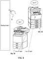
- FIG. 1 illustrates a configuration of the display system 10.
- the display system 10 includes a head mounted display 20 and a plurality of image forming apparatuses 40.
- the display system 10 includes two image forming apparatuses 40.
- the display system 10 includes a first image forming apparatus 40a and a second image forming apparatus 40b.
- the display system 10 performs various settings on the respective image forming apparatuses 40.
- the head mounted display 20 displays a setting screen of either one of the image forming apparatuses 40 (fixed terminals) such as to be viewable to a user.
- Setting screens of the respective image forming apparatuses 40 are screens through which various settings are set to the corresponding image forming apparatuses 40.
- the head mounted display 20 displays a setting screen displayed on an operation panel of either one of the image forming apparatuses 40.
- An image forming apparatus 40 that presents the displayed setting screen is a current setting target.
- the head mounted display 20 detects a user's finger motion toward the displayed setting screen.
- the head mounted display 20 transmits a signal corresponding to the user's finger motion to the current setting target. Through the above, the setting of the current setting target is updated.
- an image forming apparatus 40 that presents a currently displayed setting screen may be referred to as a currently targeted image forming apparatus 40.
- the head mounted display 20 in the present embodiment is a video see-through head mounted display.
- the head mounted display 20 includes an environment image capturing section 21.
- the environment image capturing section 21 captures an image of a surrounding environment that is inferred to be within a user's field of view.
- the environment image capturing section 21 includes an image sensor such as a complementary metal oxide semiconductor (CMOS) image sensor or a charge coupled device (CCD) image sensor.
- CMOS complementary metal oxide semiconductor
- CCD charge coupled device
- a user wearing the head mounted display 20 views the surrounding environment image captured by the environment image capturing section 21.
- the head mounted display 20 causes the user to view a setting screen of the image forming apparatus 40 present within the surrounding environment image together with the surrounding environment image. That is, the setting screen of the image forming apparatus 40 present within the surrounding environment image is displayed together with the surrounding environment image.
- the head mounted display 20 causes the user to view a setting screen of one of the image forming apparatuses 40 present within the surrounding environment image together with the surrounding environment image.
- the head mounted display 20 determines through image analysis on the surrounding environment image whether or not a user's hand is present within the surrounding environment image. When it is determined that the user's hand is present within the surrounding environment image, the head mounted display 20 detects a user's finger motion through image analysis on the surrounding environment image.
- the head mounted display 20 in the present embodiment is communicable wirelessly with each of the image forming apparatuses 40.
- the head mounted display 20 transmits a first request signal to the image forming apparatus 40 present within an image capturable range of the environment image capturing section 21.
- the first request signal is to request transmission of setting screen information.
- the head mounted display 20 receives setting screen information from the image forming apparatus 40 to which the first request signal has been transmitted.
- the head mounted display 20 displays a setting screen based on the received setting screen information.
- the head mounted display 20 transmits the first request signal to any one of the image forming apparatuses 40 present within the image capturable range of the environment image capturing section 21.
- a setting screen of one of the image forming apparatuses 40 present within the surrounding environment image is displayed.
- the head mounted display 20 displays for example an icon in a balloon-like shape in the vicinity of each of the image forming apparatuses 40 present within the surrounding environment image. Further, the head mounted display 20 transmits a second request signal to each of the image forming apparatuses 40 present within the image capturable range of the environment image capturing section 21.
- the second request signal is a signal to request transmission of use status information.
- the head mounted display 20 receives use status information from the image forming apparatuses 40 to which the second request signal has been transmitted.
- the head mounted display 20 then changes the icons of all of the image forming apparatuses 40 present within the surrounding environment image according to the corresponding use statuses.
- the icons are each set in a color corresponding to a use status.
- an icon corresponding to an image forming apparatus 40 that is available is set green.
- An icon corresponding to an image forming apparatus 40 that is being used by another user is set yellow.
- An icon corresponding to an image forming apparatus 40 that is unavailable is set red.
- FIG. 2 illustrates the head mounted display 20. Specifically, FIG. 2 illustrates the head mounted display 20 when viewed from the side of a user's face (side of user's eyeballs). In other words, FIG. 2 illustrates an inward side of the head mounted display 20.
- the head mounted display 20 in the present embodiment is a bi-ocular head mounted display.
- the head mounted display 20 accordingly includes two displays 22 (a display section) to be disposed in front of respective user's right and left eyes (eyeballs).
- the head mounted display 20 displays the same image on the two displays 22.
- the displays 22 may each be a display element such as a liquid crystal display or organic electroluminescence (organic EL) display.
- the head mounted display 20 further includes a pair of right and left eyeball image capturing sections 23.
- the pair of right and left eyeball image capturing sections 23 is disposed such as to be capable of capturing respective images of user's right and left eyes (eyeballs).
- the eyeball images captured by the respective eyeball image capturing sections 23 are used for detecting a user's line-of-sight direction.
- the head mounted display 20 specifies an image forming apparatus 40 at which the user gazes within the surrounding environment image based on the detected line-of-sight direction.
- the head mounted display 20 then displays a setting screen of the specified image forming apparatus 40.
- the displayed setting screen is changed when the image forming apparatus 40 at which the user gazes is changed among the plurality of image forming apparatuses 40 within the surrounding environment image.
- the eyeball image capturing sections 23 in the present embodiment each include a near-infrared light emitting diode (LED) 231 and an infrared camera 232.
- the infrared camera 232 may include an image sensor such as a CCD image sensor or an InGaAs/T2SL (Type II Super Lattice) sensor.
- the near-infrared LED231 irradiates a user's eyeball with a near-infrared ray.
- the infrared camera 232 captures an image of a corresponding one of the user's eyeballs irradiated with the near-infrared ray.
- an eyeball image is captured.
- the head mounted display 20 detects user's corneal reflex points and pupils from the respective eyeball images and detects a user's line-of-sight direction based on the positional relationship therebetween. In short, the user's line-of-sight direction is detected by a corneal reflex method in the present embodiment.
- the head mounted display 20 detects a point at which the user gazes based on the detected line-of-sight direction.
- the point at which the user gazes may be referred to as a point-of-gaze.
- the point-of-gaze is included in the surrounding environment image displayed on the displays 22.
- the head mounted display 20 specifies an image forming apparatus 40 at which the user gazes based on the positional relationship between the point-of-gaze and the image forming apparatuses 40 present within the surrounding environment image.
- the head mounted display 20 sets the color of the icon corresponding to the image forming apparatus 40 at which the user gazed to be a specific color. Through the above, the user can easily determine a currently targeted image forming apparatus 40.
- the head mounted display 20 may turn on and off the icon corresponding to the image forming apparatus 40 at which the user gazed.
- the head mounted display 20 may set the color of the icon corresponding to the image forming apparatus 40 at which the user gazed to be the specific color while turning on and off the icon.
- the head mounted display 20 faintly displays the setting screen of an image forming apparatus 40 that is closest to the head mounted display 20 among available image forming apparatuses 40 present within the field of view of the user wearing the head mounted display 20 (within the surrounding environment image).
- the head mounted display 20 displays the setting screen strongly (in usual distinctness).
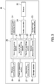
- FIG. 3 is a block diagram illustrating a configuration of the head mounted display 20.
- the head mounted display 20 further includes a display controller 24, a wireless communication interface (I/F) 25, a position detecting section 26, an orientation detecting section 27, a main controller 28, and a storage section 29 in addition to the environment image capturing section 21, the displays 22, and the eyeball image capturing sections 23.
- I/F wireless communication interface
- the display controller 24 is controlled by the main controller 28 to cause the displays 22 to display an image. Specifically, the display controller 24 causes the displays 22 to display the surrounding environment image captured by the environment image capturing section 21. The display controller 24 further causes the displays 22 to display a setting screen of an image forming apparatus 40. The display controller 24 additionally causes the displays 22 to display an icon.
- the display controller 24 in the present embodiment is a drive circuit that drives the displays 22.
- the wireless communication interface 25 is used for wireless communication with the image forming apparatuses 40.
- the communication protocol employed herein may be for example a short-range wireless communication protocol such as Bluetooth (registered Japanese trademark). However, the wireless communication protocol is not limited to the short-range wireless communication protocol.
- the position detecting section 26 detects a current position of the head mounted display 20. In other words, the position detecting section 26 detects a current position of the user wearing the head mounted display 20.
- the position detecting section 26 has a global positioning system (GPS) function, for example.
- GPS global positioning system
- the orientation detecting section 27 detects an orientation of the head mounted display 20. In other words, the orientation detecting section 27 detects an orientation of the face of the user wearing the head mounted display 20.
- the orientation detecting section 27 includes an electronic compass, for example.
- the main controller 28 performs various processing such as numeric calculation, information processing, and device control through execution of programs stored in the storage section 29.
- the main controller 28 may include a computing device such as a central processing unit (CPU) or a micro processing unit (MPU).
- CPU central processing unit
- MPU micro processing unit
- the storage section 29 stores therein programs and setting information.
- the storage section 29 also stores therein icon images, mapping information, etc.
- the mapping information includes information on coordinates (positions) of the respective image forming apparatuses 40 in a real space (three-dimensional space).
- the storage section 29 may be constituted by a random access memory (RAM) and a read only memory (ROM), for example.
- the storage section may include a hard disk device (HDD).
- the main controller 28 in the present embodiment functions as a first determination section 31, a line-of-sight direction detecting section 32, a terminal specifying section 33, and a second determination section 34 through execution of programs stored in the storage section 29. As such, the main controller 28 executes respective processing that the first determination section 31, the line-of-sight direction detecting section 32, the terminal specifying section 33, and the second determination section 34 are to perform.
- the first determination section 31 determines whether or not there are any image forming apparatuses 40 (fixed terminals) present within the field of view of the user wearing the head mounted display 20 (within the surrounding environment image). In the present embodiment, the first determination section 31 determines whether or not there are any image forming apparatuses 40 present within the surrounding environment image by image analysis on the surrounding environment image captured by the environment image capturing section 21. For example, determination as to whether or not there are any image forming apparatuses 40 present within the surrounding environment image may be performed by matching. Specifically, the contours of objects included in surrounding environment image are extracted through image analysis. The storage section 29 stores therein a reference contour data group indicating contours of the respective image forming apparatuses 40. The first determination section 31 perform collation (matching) between the extracted contours and the reference contours in the reference contour data group stored in advance. Through the collation, whether or not there are any image forming apparatuses 40 present within the surrounding environment image is determined.
- the main controller 28 causes the displays 22 to display an icon.
- the main controller 28 first specifies an image forming apparatus 40 present within the image capturable range of the environment image capturing section 21 (within the surrounding environment image) based on the mapping information stored in the storage section 29, information on the current position of the head mounted display 20 (user's current position) detected by the position detecting section 26, and information on the orientation of the head mounted display 20 (orientation of the user's face) detected by the orientation detecting section 27.
- the main controller 28 transmits the second request signal to the specified image forming apparatus 40 via the wireless communication interface 25. That is, the head mounted display 20 requests the image forming apparatus 40 present within the image capturable range of the environment image capturing section 21 to transmit use status information.
- the main controller 28 causes the displays 22 to display the surrounding environment image including an icon. Specifically, an icon in a color according to the use status is displayed in the vicinity of the specified image forming apparatus 40 in the surrounding environment image.
- the line-of-sight direction detecting section 32 detects a user's line-of-sight direction by the corneal reflex method based on the eyeball images captured by the eyeball image capturing sections 23.
- the terminal specifying section 33 specifies one of the image forming apparatuses 40 present within the surrounding environment image based on the line-of-sight direction detected by the line-of-sight direction detecting section 32.
- the display controller 24 causes the displays 22 to display a setting screen of the image forming apparatus 40 specified by the terminal specifying section 33.
- the terminal specifying section 33 specifies an image forming apparatus 40 at which the user gazes. That is, the terminal specifying section 33 detects based on the user's line-of-sight direction, the user's point-of-gaze within the surrounding environment image displayed on the displays 22. The terminal specifying section 33 then performs first detection. Specifically, the terminal specifying section 33 detects the image forming apparatus 40 within the surrounding environment image in which the point-of-gaze is included. The first detection is performed based on the positional relationship between the image forming apparatus 40 and the point-of-gaze in the surrounding environment image. By the first detection, the image forming apparatus 40 at which the user gazes is specified.
- the main controller 28 transmits the first request signal via the wireless communication interface 25 to the image forming apparatus 40 specified through the first detection by the terminal specifying section 33. That is, transmission of setting screen information is requested to the image forming apparatus 40 specified through the first detection.
- the main controller 28 causes the displays 22 to display the setting screen based on the setting screen information received via the wireless communication interface 25.
- the setting screen is located (displayed) in a specific region in the image displayed by each of the displays 22
- the image forming apparatus 40 specified through the first detection by the terminal specifying section 33 is changed when the image forming apparatus 40 at which the user gazes is change among the plurality of image forming apparatuses 40 present within the surrounding environment image.
- the main controller 28 transmits the first request signal each time the image forming apparatus 40 specified through the first detection by the terminal specifying section 33 is changed.
- the setting screen displayed on the displays 22 is changed. In other words, once a setting screen of an image forming apparatus 40 is displayed, the displayed setting screen is not changed until the point-of-gaze is included in another image forming apparatus 40 present within the surrounding environment image.
- the terminal specifying section 33 performs second detection.
- the second detection is performed in a situation in which the point-of-gaze is deviated from all of the image forming apparatuses 40.
- the second detection is performed in a situation in which the user does not gaze at any image forming apparatus 40.
- the terminal specifying section 33 detects (specifies) an image forming apparatus 40 that satisfies an initial condition among available image forming apparatuses 40 present within the image capturable range of the environment image capturing section 21.
- the terminal specifying section 33 detects an image forming apparatus 40 located the closest to the head mounted display 20.
- the second detection can be performed based on the use status information of each of the image forming apparatuses 40 present within the surrounding environment image, information on the current position of the head mounted display 20 detected by the position detecting section 26, and mapping information stored in the storage section 29.
- the main controller 28 transmits the first request signal via the wireless communication interface 25 to the image forming apparatus 40 specified through the second detection by the terminal specifying section 33. That is, transmission of setting screen information is requested to the image forming apparatus 40 specified through the second detection.
- the main controller 28 causes the displays 22 to faintly display a setting screen based on the setting screen information received via the wireless communication interface 25.
- the setting screen is located (displayed) in the specific region in the image displayed by each of the displays 22.
- the display 22 display the setting screen of the image forming apparatus 40 at which the user gazes. For example, once the point-of-gaze is included in an image forming apparatus 40 within the surrounding environment image that satisfies the initial condition, the setting screen being displayed faintly is displayed in the usual distinctness. Further, when the user gazes at the setting screen displayed faintly, that is, when the point-of-gaze is included in the setting screen displayed faintly, the setting screen displayed faintly is displayed in the usual distinctness in the present embodiment.
- the main controller 28 in the present embodiment sets the color of the icon corresponding to the currently targeted image forming apparatus 40 to a specific color.
- the main controller 28 further sets the icon corresponding to the currently targeted image forming apparatus 40 to be turned on and off.
- the second determination section 34 determines based on the surrounding environment image captured by the environment image capturing section 21 whether or not a user's hand (specific object) is present within the user's field of view (surrounding environment image). During determination by the second determination section 34 that the hand is present within the surrounding environment image, the main controller 28 inhibits change of the setting screen displayed on the displays 22. That is, during the time when the hand is present within the surrounding environment image, the setting screen being displayed on the displays 22 is not changed even if the point-of-gaze moves to an image forming apparatus 40 other than the currently targeted image forming apparatus 40 in the surrounding environment image. Determination as to whether or not the hand (specific object) is present within the surrounding environment image can be performed by matching, for example.
- the main controller 28 may change the setting screen.
- the main controller 28 may change the setting screen when the user selects an image forming apparatus 40 other than the currently targeted image forming apparatus 40 in a situation in which change of the setting screen is inhibited in the presence of the detected hand.
- the display controller 24 causes the displays 22 to display an image in which the setting screens are partially overlapped with each other and mutually displaced in a given direction in the present embodiment. Further, the display controller 24 changes a setting screen that is to be located uppermost (to be located on top) among the plurality of setting screens according to the line-of-sight direction detected by the line-of-sight direction detecting section 32.
- the main controller 28 generates based on the setting screen information, an image in which the setting screens partially overlapped with each other and mutually displaced in the given direction.
- the main controller 28 further performs third detection based on the line-of-sight direction detected by the line-of-sight direction detecting section 32.
- the third detection is to detect a setting screen in which the point-of-gaze is included from among the plurality of setting screens.
- the main controller 28 updates the image of the setting screens displayed on the displays 22 such that the setting screen in which the point-of-gaze is included is located uppermost.
- Change to a setting screen that is to be located uppermost may be inhibited during determination by the second determination section 34 that the hand is present within the surrounding environment image.
- Change to a setting screen that is to be located uppermost may be inhibited during determination by the second determination section 34 that the hand is present within the surrounding environment image.
- a situation in which the setting screen is adversely changed in setting the image forming apparatus 40 can be prevented.
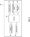
- FIG. 4 is a block diagram illustrating the configuration of the image forming apparatus 40.
- the image forming apparatus 40 includes an operation panel 41, a FAX communication section 42, an image forming section 43, a wireless communication interface (I/F) 44, a controller 45, and a storage section 46.
- I/F wireless communication interface
- the operation panel 41 includes an input device such as buttons, and a display device such as a liquid crystal display.
- a user operation on the operation panel 41 (input device) causes the image forming apparatus 40 to perform processing corresponding to the operation.
- the user can cause the image forming apparatus 40 to perform various processing through the operation panel 41 (input device).
- the display device displays various setting screens.
- the display device may be a touch panel. In the above configuration, the display device also functions as the input device.
- the FAX communication section 42 is connected to a public telephone line to communicate with a destination facsimile machine.
- the image forming section 43 forms an image on a recording medium such as a sheet of paper.
- the image forming section 43 may be an electrographic image forming section or an inkjet image forming section.
- a typical electrographic image forming section includes a photosensitive drum, an optical scanning device, a developing device, and a transfer member.
- the optical scanning device forms an electrostatic latent image on the circumferential surface of the photosensitive drum.
- the developing device supplies toner to the circumferential surface of the photosensitive drum to develop the electrostatic latent image. Through the above, a toner image is formed on the circumferential surface of the photosensitive drum.
- the transfer member transfers the toner image to a recording medium.
- a typical inkjet image forming section includes a recording head such as a line head or a serial head. The recording head discharges ink droplets toward a recording medium. Ink droplets struck on the recording medium form an image on the recording medium.
- the wireless communication interface 44 is used for wireless communication with the head mounted display 20. That is, the wireless communication protocol that the wireless communication interface 44 of the image forming apparatus 40 employs is the same as the wireless communication protocol that the wireless communication interface 25 of the head mounted display 20 employs.
- the controller 45 performs various processing such as numeric calculation, information processing, and device control through execution of programs stored in the storage section 46.
- the controller 45 may include an computing device such as a CPU or a MPU.
- the storage section 46 stores therein programs and setting information.
- the storage section 46 stores therein information on various setting screens.
- the storage section 46 may be constituted by a RAM and a ROM, for example.
- the storage section 46 may include a HDD.
- the controller 45 transmits the setting screen information stored in the storage section 46 to the head mounted display 20 via the wireless communication interface 44.
- the controller 45 transmits information on the use status of the image forming apparatus 40 to the head mounted display 20 via the wireless communication interface 44.
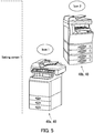
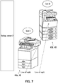
- FIGS. 5-9 and 10A-10C each illustrate an image displayed in the display system 10.
- Line-of-sight directions are each indicated by an arrow in FIGS. 5-9 and 10A-10C .
- the point pointed by the tip end of each arrow representing the line-of-sight direction is the user's point-of-gaze.
- FIGS. 5-9 each illustrate a setting screen displayed in a situation in which two image forming apparatuses 40 (the first image forming apparatus 40a and the second image forming apparatus 40b) are present within the surrounding environment image.
- the setting screen of an image forming apparatus 40 that satisfies the initial condition is displayed at a specific location (on the left side of the surrounding environment image that the displays 22 display in the present embodiment), as illustrated in FIG. 5 . That is, the setting screen of an image forming apparatus 40 the closest to the head mounted display 20 is displayed among available image forming apparatuses 40 present within the image capturable range of the environment image capturing section 21.
- “Setting screen 1" of the first image forming apparatus 40a is displayed.
- “Setting screen 1" of the first image forming apparatus 40a is displayed faintly as compared with the usual distinctness. The broken line in FIG. 5 indicates that "Setting screen 1" is displayed faintly.
- the displays 22 display an image in which the setting screens are partially overlapped with each other and mutually displaced in the given direction, as illustrated in FIGS. 10A-10C .
- the setting screens are displayed such that the user can recognize tabs (portions indicating respective words "Copy", "Send", "Box”, and "FAX") of the respective setting screens, as illustrated in FIG. 10A-10C .
- the tabs indicate types of the respective setting screen.
- FIGS. 10A-10C each illustrate an example of setting screens for a copy function, a send function, a box function, and a facsimileing function.
- the send function is a function of transmitting image data accumulated in an image forming apparatus to another image forming apparatus, an external personal computer (PC), or the like.
- the box function is a function of accumulating image data for each user.
- FIG. 11 is a flowchart depicting the operation of the display system 10.
- the head mounted display 20 When the head mounted display 20 is powered on, the surrounding environment image captured by the environment image capturing section 21 serving as user's view field information is displayed (reflected) on the displays 22 of the head mounted display 20 (Step S1).
- the first determination section 31 determines whether or not there are any image forming apparatuses 40 present within the surrounding environment image (Step S2).
- the image forming apparatuses 40 in the present embodiment each are an image forming apparatus (terminal) for which the display system 10 is capable of performing setting.
- the routine proceeds to Step S3.
- the view field information (surrounding environment image) displayed on the displays 22 of the head mounted display 20 is updated (Step S3) and the routine returns to Step S2. Thereafter, Steps S2 and S3 are repeated until any image forming apparatus 40 is included in the surrounding environment image.
- Step S2 When the first determination section 31 (main controller 28) determines that there is an image forming apparatus 40 present within the surrounding environment image (Yes at Step S2), the routine proceeds to Step S4.
- Step S4 an icon is displayed in the vicinity of the image forming apparatus 40 in the surrounding environment image.
- the line-of-sight direction detecting section 32 main controller 28
- the terminal specifying section 33 main controller 28
- the routine then performs the first detection based on the line-of-sight direction detected by the line-of-sight direction detecting section 32. That is, processing to detect an image forming apparatus 40 at which the user gazes is executed (Step S5).
- the routine returns to Step S3.
- the routine proceeds to Step S6.
- Step S6 an icon corresponding to the image forming apparatus 40 at which the user gazes is displayed in a manner to be turned on and off. Further, a setting screen of the image forming apparatus 40 at which the user gazes is displayed.
- the second determination section 34 determines whether or not a hand is present within the surrounding environment image (Step S7).
- the routine returns to Step S3.
- the state of the main controller 28 of the head mounted display 20 transitions to a state in which change of the setting screen is inhibited (Step S8).
- the second determination section 34 determines whether or not the hand is present within the surrounding environment image (Step S9).
- the routine returns to Step S3.
- the main controller 28 of the head mounted display 20 determines whether or not a user operation to set the image forming apparatus 40 is complete (Step S10).
- the main controller 28 of the head mounted display 20 detects whether or not the user operation to set the image forming apparatus 40 is complete based on whether or not an "OK" button in the setting screen is pressed.
- Step S10 When the main controller 28 determines that the user operation to set the image forming apparatus 40 is not complete (No at Step S10), the routine returns to Step S9. By contrast, when the main controller 28 determines that the user operation to set the image forming apparatus 40 is complete (Yes at Step S10), the routine ends.
- an image is displayed in which the plurality of setting screens are partially overlapped with each other and mutually displaced in the given direction. Further, a setting screen that is a target for a user operation can be changed according to a user's line-of-sight direction (point-of-gaze). This can improve user-friendliness.
- the terminals that each are to be a setting target are the image forming apparatuses 40 in the embodiment of the present disclosure, which however should not be taken to limit the present disclosure.
- the present disclosure is applicable to various types of terminals that each present a setting screen.
- the present disclosure is applicable to electronic devices such as personal computers.
- the pair of right and left displays 22 displays the same image in the embodiment of the present disclosure, which however should not be taken to limit the present disclosure.
- a three-dimensional image (3D image) may be displayed by the pair of right and left displays 22. That is, the right and left displays 22 may display two images with an image capturing angle shifted from each other so that view a stereographic image is visible to a user.
- the setting screens can be displayed in a manner to be mutually displaced in a depth direction.
- the main controller 28 of the head mounted display 20 detects the three-dimensional coordinates of the user's point-of-gaze in a real space based on the user's line-of-sight direction. Further, the main controller 28 of the head mounted display 20 compares the three-dimensional coordinates of the point-of-gaze in the real space with the respective three-dimensional coordinates of the setting screens in the three-dimensional image to specify a setting screen at which the user gazes.
- the setting of an image forming apparatus 40 is updated according to signals corresponding to the user's finger motion in the embodiment of the present disclosure, which however should not be taken to limit the present disclosure.
- the setting of an image forming apparatus 40 may be updated through generation of signals corresponding to a motion of an operation member having a specific shape (for example, a tip end of a pen having a specific shape) rather than the user's finger.
- An image forming apparatus 40 at which the user gazes is specified based on the detected user's line-of-sight direction in the embodiment of the present disclosure, which however should not be taken to limit the present disclosure.
- an icon at which the user gazes may be detected based on the user's line-of-sight direction.
- the displays 22 are caused to display the setting screen of an image forming apparatus 40 corresponding to the icon at which the user gazes.
- Determination as to whether or not there are any image forming apparatuses 40 present within the surrounding environment image is performed through matching in the embodiment of the present disclosure, which however should not be taken to limit the present disclosure. Whether or not there are any image forming apparatuses 40 present within the surrounding environment image may be determined based on coordinates (positions) of the respective image forming apparatuses 40 in the real space, a current position of the head mounted display 20 (user's current position), and an orientation of the head mounted display 20 (orientation of user's face).
- An image forming apparatus 40 present within the user's field of view is specified based on the coordinates (positions) of the respective image forming apparatuses 40 in the real space, the current position of the head mounted display 20 (user's current position), and the orientation of the head mounted display 20 (orientation of the user's face), which however should not be taken to limit the present disclosure.
- an image forming apparatus 40 present within the user's field of view may be specified by matching.
- each image forming apparatus 40 present within the user's field of view may be specified in a manner that marks unique to the respective image forming apparatuses 40 are assigned to the respective image forming apparatuses 40 and a mark is specified through image analysis on the surrounding environment image.
- Change of the setting screen and change to a setting screen that is to be located uppermost are inhibited upon detection of a hand within the user's field of view in the embodiment of the present disclosure, which however should not be taken to limit the present disclosure.
- change of the setting screen and change to a setting screen that is to be located uppermost may be inhibited upon detection of an operation member having a specific shape (for example, a tip end of a pen having a specific shape) rather than the user's hand.
- the head mounted display 20 is of video see-through type in the embodiment of the present disclosure, which however should not be taken to limit the present disclosure.
- the head mounted display 20 may be of optical see-through type.
- the optical see-through type head mounted display causes a user to directly view an external environment (user's surrounding environment).
- the display controller 24 may be a projector.
- the display controller 24 may project (image) a setting screen and an icon on a user's retina or an optical element such as a half mirror.
- the displays 22 may each be a display element that transmits light, such as a liquid crystal display element.
- an image forming apparatus 40 at which the user gazes can be specified by comparing the three-dimensional coordinates of the user's point-of-gaze in the real space with the three-dimensional coordinates of the respective image forming apparatuses 40 in the real space.
- the three-dimensional coordinates of the point-of-gaze can be calculated based on the current position of the head mounted display 20 (user's current position), the orientation of the head mounted display 20 (orientation of the user's face), and the user's line-of-sight direction.
- the head mounted display 20 is a bi-ocular head mounted display in the embodiment of the present disclosure, which however should not be taken to limit the present disclosure.
- the head mounted display 20 may be a monocular or binocular head mounted display.
- the monocular head mounted display causes one of user's right and left eyes to view a calculated image.
- the binocular head mounted display causes respective user's right and left eyes to view different calculated images.
- the binocular head mounted display can cause the user to view a three-dimensional image (3D image).
- a three-dimensional image is displayed using a video see-through type head mounted display
- the user can view the surrounding environment without an uneasy feeling.
- an optical see-through type head mounted display is employed, a stereographic icon image can be displayed as if the icon is actually present on an image forming apparatus that the user directly views.
- an image forming apparatus 40 at which the user gazes can be specified by comparing the three-dimensional coordinates of the user's point-of-gaze in the real space with the three-dimensional coordinates of the respective image forming apparatuses 40 within the three-dimensional image.
- an image forming apparatus 40 at which the user gazes can be specified by comparing the three-dimensional coordinates of the user's point-of-gaze in the real space with the three-dimensional coordinates of the icon within the three-dimensional image.
- the user's line-of-sight direction is detected by the corneal reflex method in the embodiment of the present disclosure, which however should not be taken to limit the present disclosure.
- the line-of-sight direction may be detected based on the position of an iris relative to an inner canthus of a user's eye that is obtained through image analysis on an eyeball image captured using a camera that captures viewable light.
- a setting screen of an image forming apparatus 40 is displayed on the displays 22 of the head mounted display 20 in the embodiment of the present disclosure, which however should not be taken to limit the present disclosure.
- the displays 22 may display an image of an operation panel of an image forming apparatus 40.
- the color of an icon is changed according to the use status of a corresponding image forming apparatus 40 in the embodiment of the present disclosure, which however should not be taken to limit the present disclosure.
- the shape of the icon may be changed according to the use status of the corresponding image forming apparatus 40.
Description
- The present disclosure relates to display systems and head mounted displays.
- Recently, development is promoted in a technique for setting an image forming apparatus through a head mounted display. The head mounted display is a type of wearable terminals or wearable computers. The head mounted display displays an image so as to be viewable to a user. In other words, the head mounted display displays information. For example, development is promoted in a technique for setting an image forming apparatus through a monocular head mounted display of retina projection type.
- Specifically, when a main body of the head mounted display is powered on, a setting screen or an operation panel of a specific image forming apparatus is projected to a user's retina. Typically, the setting screen displayed on the operation panel of the specific image forming apparatus is projected to the retia. Alternatively, the operation panel of the specific image forming apparatus is projected to the retina. An image of at least a part of a user's viewable range is captured. When the user moves a finger within the captured range (user's viewable range) for operating the setting screen or the operation panel, the captured image is analyzed for detecting the user's finger motion. Through comparison between the coordinates of the finger tip of the moving finger and the coordinates of respective keys included in the setting screen or the operation panel projected to the retina, a key that the user operates is determined. The retina projection type may be called see-through type.
-
EP 2 372 495 A2 -
EP 2 824 541 A1 - The present invention provides a head mounted display according to
claim 1 and a display system according to claim 8. Further embodiments of the invention are described in the dependent claims. -
-
FIG. 1 illustrates a configuration of a display system according to an embodiment. -
FIG. 2 illustrates a head mounted display according to the embodiment. -
FIG. 3 is a block diagram illustrating a configuration of the head mounted display according to the embodiment. -
FIG. 4 is a block diagram illustrating a configuration of an image forming apparatus according to the embodiment. -
FIG. 5 illustrates an image displayed in the display system according to the embodiment. -
FIG. 6 illustrates an image displayed in the display system according to the embodiment. -
FIG. 7 illustrates an image displayed in the display system according to the embodiment. -
FIG. 8 illustrates an image displayed in the display system according to the embodiment. -
FIG. 9 illustrates an image displayed in the display system according to the embodiment. -
FIGS. 10A-10C each illustrate an image displayed in the display system according to the embodiment. -
FIG. 11 is a flowchart depicting an operation of the display system according to the embodiment. - The following describes an embodiment of the present disclosure with reference to the drawings. Elements in the drawings that are the same or equivalent are marked by the same reference signs. Furthermore, description of such elements is not repeated.
- The following explains a configuration of a
display system 10 according to the present embodiment with reference toFIG. 1. FIG. 1 illustrates a configuration of thedisplay system 10. As illustrated inFIG 1 , thedisplay system 10 includes a head mounteddisplay 20 and a plurality ofimage forming apparatuses 40. In the present embodiment, thedisplay system 10 includes twoimage forming apparatuses 40. Specifically, thedisplay system 10 includes a firstimage forming apparatus 40a and a secondimage forming apparatus 40b. - The
display system 10 performs various settings on the respectiveimage forming apparatuses 40. Specifically, the head mounteddisplay 20 displays a setting screen of either one of the image forming apparatuses 40 (fixed terminals) such as to be viewable to a user. Setting screens of the respectiveimage forming apparatuses 40 are screens through which various settings are set to the correspondingimage forming apparatuses 40. Typically, the head mounteddisplay 20 displays a setting screen displayed on an operation panel of either one of theimage forming apparatuses 40. Animage forming apparatus 40 that presents the displayed setting screen is a current setting target. The head mounteddisplay 20 detects a user's finger motion toward the displayed setting screen. The head mounteddisplay 20 transmits a signal corresponding to the user's finger motion to the current setting target. Through the above, the setting of the current setting target is updated. In the following description, animage forming apparatus 40 that presents a currently displayed setting screen may be referred to as a currently targetedimage forming apparatus 40. - The head mounted
display 20 in the present embodiment is a video see-through head mounted display. The head mounteddisplay 20 includes an environmentimage capturing section 21. The environmentimage capturing section 21 captures an image of a surrounding environment that is inferred to be within a user's field of view. The environmentimage capturing section 21 includes an image sensor such as a complementary metal oxide semiconductor (CMOS) image sensor or a charge coupled device (CCD) image sensor. - A user wearing the head mounted
display 20 views the surrounding environment image captured by the environmentimage capturing section 21. In a situation in which a singleimage forming apparatus 40 is present within a field of view of the user wearing the head mounted display 20 (within the surrounding environment image), the head mounteddisplay 20 causes the user to view a setting screen of theimage forming apparatus 40 present within the surrounding environment image together with the surrounding environment image. That is, the setting screen of theimage forming apparatus 40 present within the surrounding environment image is displayed together with the surrounding environment image. In a situation in which a plurality ofimage forming apparatuses 40 are present within the field of view of the user wearing the head mounted display 20 (within the surrounding environment image), the head mounteddisplay 20 causes the user to view a setting screen of one of theimage forming apparatuses 40 present within the surrounding environment image together with the surrounding environment image. - The head mounted
display 20 determines through image analysis on the surrounding environment image whether or not a user's hand is present within the surrounding environment image. When it is determined that the user's hand is present within the surrounding environment image, the head mounteddisplay 20 detects a user's finger motion through image analysis on the surrounding environment image. - The head mounted
display 20 in the present embodiment is communicable wirelessly with each of theimage forming apparatuses 40. In a situation in which a singleimage forming apparatus 40 is present within the field of view of the user wearing the head mounted display 20 (within the surrounding environment image), the head mounteddisplay 20 transmits a first request signal to theimage forming apparatus 40 present within an image capturable range of the environmentimage capturing section 21. The first request signal is to request transmission of setting screen information. The head mounteddisplay 20 receives setting screen information from theimage forming apparatus 40 to which the first request signal has been transmitted. The head mounteddisplay 20 displays a setting screen based on the received setting screen information. In a situation in which a plurality ofimage forming apparatuses 40 are present within the field of view of the user wearing the head mounted display 20 (within the surrounding environment image), the head mounteddisplay 20 transmits the first request signal to any one of theimage forming apparatuses 40 present within the image capturable range of the environmentimage capturing section 21. Through the above, a setting screen of one of theimage forming apparatuses 40 present within the surrounding environment image is displayed. - The head mounted
display 20 displays for example an icon in a balloon-like shape in the vicinity of each of theimage forming apparatuses 40 present within the surrounding environment image. Further, the head mounteddisplay 20 transmits a second request signal to each of theimage forming apparatuses 40 present within the image capturable range of the environmentimage capturing section 21. The second request signal is a signal to request transmission of use status information. In response, the head mounteddisplay 20 receives use status information from theimage forming apparatuses 40 to which the second request signal has been transmitted. The head mounteddisplay 20 then changes the icons of all of theimage forming apparatuses 40 present within the surrounding environment image according to the corresponding use statuses. In the present embodiment, the icons are each set in a color corresponding to a use status. For example, an icon corresponding to animage forming apparatus 40 that is available is set green. An icon corresponding to animage forming apparatus 40 that is being used by another user is set yellow. An icon corresponding to animage forming apparatus 40 that is unavailable is set red. By setting as above, the user can easily determine which of theimage forming apparatuses 40 is currently available. This can improve user friendliness. - With reference to
FIGS. 2 and3 , a configuration of the head mounteddisplay 20 will be described next.FIG. 2 illustrates the head mounteddisplay 20. Specifically,FIG. 2 illustrates the head mounteddisplay 20 when viewed from the side of a user's face (side of user's eyeballs). In other words,FIG. 2 illustrates an inward side of the head mounteddisplay 20. - As illustrated in
FIG. 2 , the head mounteddisplay 20 in the present embodiment is a bi-ocular head mounted display. The head mounteddisplay 20 accordingly includes two displays 22 (a display section) to be disposed in front of respective user's right and left eyes (eyeballs). The head mounteddisplay 20 displays the same image on the two displays 22. Thedisplays 22 may each be a display element such as a liquid crystal display or organic electroluminescence (organic EL) display. - The head mounted
display 20 further includes a pair of right and left eyeballimage capturing sections 23. The pair of right and left eyeballimage capturing sections 23 is disposed such as to be capable of capturing respective images of user's right and left eyes (eyeballs). The eyeball images captured by the respective eyeballimage capturing sections 23 are used for detecting a user's line-of-sight direction. The head mounteddisplay 20 specifies animage forming apparatus 40 at which the user gazes within the surrounding environment image based on the detected line-of-sight direction. The head mounteddisplay 20 then displays a setting screen of the specifiedimage forming apparatus 40. In a situation in which a plurality ofimage forming apparatuses 40 are present within the field of view of the user wearing the head mounted display 20 (within the surrounding environment image), the displayed setting screen is changed when theimage forming apparatus 40 at which the user gazes is changed among the plurality ofimage forming apparatuses 40 within the surrounding environment image. - The eyeball
image capturing sections 23 in the present embodiment each include a near-infrared light emitting diode (LED) 231 and aninfrared camera 232. Theinfrared camera 232 may include an image sensor such as a CCD image sensor or an InGaAs/T2SL (Type II Super Lattice) sensor. - In a configuration in which the eyeball
image capturing sections 23 each include the near-infrared LED231 and theinfrared camera 232, the near-infrared LED231 irradiates a user's eyeball with a near-infrared ray. Theinfrared camera 232 captures an image of a corresponding one of the user's eyeballs irradiated with the near-infrared ray. Through the above, an eyeball image is captured. The head mounteddisplay 20 detects user's corneal reflex points and pupils from the respective eyeball images and detects a user's line-of-sight direction based on the positional relationship therebetween. In short, the user's line-of-sight direction is detected by a corneal reflex method in the present embodiment. - The head mounted
display 20 detects a point at which the user gazes based on the detected line-of-sight direction. In the following description, the point at which the user gazes may be referred to as a point-of-gaze. In the present embodiment, the point-of-gaze is included in the surrounding environment image displayed on thedisplays 22. The head mounteddisplay 20 specifies animage forming apparatus 40 at which the user gazes based on the positional relationship between the point-of-gaze and theimage forming apparatuses 40 present within the surrounding environment image. - Further, the head mounted
display 20 sets the color of the icon corresponding to theimage forming apparatus 40 at which the user gazed to be a specific color. Through the above, the user can easily determine a currently targetedimage forming apparatus 40. The head mounteddisplay 20 may turn on and off the icon corresponding to theimage forming apparatus 40 at which the user gazed. Alternatively, the head mounteddisplay 20 may set the color of the icon corresponding to theimage forming apparatus 40 at which the user gazed to be the specific color while turning on and off the icon. - In a situation in which the point-of-gaze is deviated from all of the
image forming apparatus 40 present within the surrounding environment image, the head mounteddisplay 20 faintly displays the setting screen of animage forming apparatus 40 that is closest to the head mounteddisplay 20 among availableimage forming apparatuses 40 present within the field of view of the user wearing the head mounted display 20 (within the surrounding environment image). When the user thereafter gazes at animage forming apparatus 40 corresponding to the faintly displayed setting screen or the user gazes at the faintly displayed setting screen, the head mounteddisplay 20 displays the setting screen strongly (in usual distinctness). -
FIG. 3 is a block diagram illustrating a configuration of the head mounteddisplay 20. As illustrated inFIG. 3 , the head mounteddisplay 20 further includes adisplay controller 24, a wireless communication interface (I/F) 25, aposition detecting section 26, anorientation detecting section 27, amain controller 28, and astorage section 29 in addition to the environmentimage capturing section 21, thedisplays 22, and the eyeballimage capturing sections 23. - The
display controller 24 is controlled by themain controller 28 to cause thedisplays 22 to display an image. Specifically, thedisplay controller 24 causes thedisplays 22 to display the surrounding environment image captured by the environmentimage capturing section 21. Thedisplay controller 24 further causes thedisplays 22 to display a setting screen of animage forming apparatus 40. Thedisplay controller 24 additionally causes thedisplays 22 to display an icon. Thedisplay controller 24 in the present embodiment is a drive circuit that drives thedisplays 22. - The
wireless communication interface 25 is used for wireless communication with theimage forming apparatuses 40. The communication protocol employed herein may be for example a short-range wireless communication protocol such as Bluetooth (registered Japanese trademark). However, the wireless communication protocol is not limited to the short-range wireless communication protocol. - The
position detecting section 26 detects a current position of the head mounteddisplay 20. In other words, theposition detecting section 26 detects a current position of the user wearing the head mounteddisplay 20. Theposition detecting section 26 has a global positioning system (GPS) function, for example. - The
orientation detecting section 27 detects an orientation of the head mounteddisplay 20. In other words, theorientation detecting section 27 detects an orientation of the face of the user wearing the head mounteddisplay 20. Theorientation detecting section 27 includes an electronic compass, for example. - The
main controller 28 performs various processing such as numeric calculation, information processing, and device control through execution of programs stored in thestorage section 29. Themain controller 28 may include a computing device such as a central processing unit (CPU) or a micro processing unit (MPU). - The
storage section 29 stores therein programs and setting information. Thestorage section 29 also stores therein icon images, mapping information, etc. The mapping information includes information on coordinates (positions) of the respectiveimage forming apparatuses 40 in a real space (three-dimensional space). Thestorage section 29 may be constituted by a random access memory (RAM) and a read only memory (ROM), for example. The storage section may include a hard disk device (HDD). - The
main controller 28 in the present embodiment functions as afirst determination section 31, a line-of-sightdirection detecting section 32, aterminal specifying section 33, and asecond determination section 34 through execution of programs stored in thestorage section 29. As such, themain controller 28 executes respective processing that thefirst determination section 31, the line-of-sightdirection detecting section 32, theterminal specifying section 33, and thesecond determination section 34 are to perform. - The
first determination section 31 determines whether or not there are any image forming apparatuses 40 (fixed terminals) present within the field of view of the user wearing the head mounted display 20 (within the surrounding environment image). In the present embodiment, thefirst determination section 31 determines whether or not there are anyimage forming apparatuses 40 present within the surrounding environment image by image analysis on the surrounding environment image captured by the environmentimage capturing section 21. For example, determination as to whether or not there are anyimage forming apparatuses 40 present within the surrounding environment image may be performed by matching. Specifically, the contours of objects included in surrounding environment image are extracted through image analysis. Thestorage section 29 stores therein a reference contour data group indicating contours of the respectiveimage forming apparatuses 40. Thefirst determination section 31 perform collation (matching) between the extracted contours and the reference contours in the reference contour data group stored in advance. Through the collation, whether or not there are anyimage forming apparatuses 40 present within the surrounding environment image is determined. - When the
first determination section 31 determines that there is animage forming apparatus 40 present within the field of view of the user wearing the head mounted display 20 (within the surrounding environment image), themain controller 28 causes thedisplays 22 to display an icon. - In the present embodiment, the
main controller 28 first specifies animage forming apparatus 40 present within the image capturable range of the environment image capturing section 21 (within the surrounding environment image) based on the mapping information stored in thestorage section 29, information on the current position of the head mounted display 20 (user's current position) detected by theposition detecting section 26, and information on the orientation of the head mounted display 20 (orientation of the user's face) detected by theorientation detecting section 27. - Subsequently, the
main controller 28 transmits the second request signal to the specifiedimage forming apparatus 40 via thewireless communication interface 25. That is, the head mounteddisplay 20 requests theimage forming apparatus 40 present within the image capturable range of the environmentimage capturing section 21 to transmit use status information. - Once the
wireless communication interface 25 receives the use status information from the specifiedimage forming apparatus 40, themain controller 28 causes thedisplays 22 to display the surrounding environment image including an icon. Specifically, an icon in a color according to the use status is displayed in the vicinity of the specifiedimage forming apparatus 40 in the surrounding environment image. - The line-of-sight
direction detecting section 32 detects a user's line-of-sight direction by the corneal reflex method based on the eyeball images captured by the eyeballimage capturing sections 23. In a situation in which a plurality of image forming apparatuses 40 (plural fixed terminals) are present within the surrounding environment image, theterminal specifying section 33 specifies one of theimage forming apparatuses 40 present within the surrounding environment image based on the line-of-sight direction detected by the line-of-sightdirection detecting section 32. Thedisplay controller 24 causes thedisplays 22 to display a setting screen of theimage forming apparatus 40 specified by theterminal specifying section 33. - Specifically, the
terminal specifying section 33 specifies animage forming apparatus 40 at which the user gazes. That is, theterminal specifying section 33 detects based on the user's line-of-sight direction, the user's point-of-gaze within the surrounding environment image displayed on thedisplays 22. Theterminal specifying section 33 then performs first detection. Specifically, theterminal specifying section 33 detects theimage forming apparatus 40 within the surrounding environment image in which the point-of-gaze is included. The first detection is performed based on the positional relationship between theimage forming apparatus 40 and the point-of-gaze in the surrounding environment image. By the first detection, theimage forming apparatus 40 at which the user gazes is specified. - The
main controller 28 transmits the first request signal via thewireless communication interface 25 to theimage forming apparatus 40 specified through the first detection by theterminal specifying section 33. That is, transmission of setting screen information is requested to theimage forming apparatus 40 specified through the first detection. Themain controller 28 causes thedisplays 22 to display the setting screen based on the setting screen information received via thewireless communication interface 25. The setting screen is located (displayed) in a specific region in the image displayed by each of thedisplays 22 - In a situation in which a plurality of
image forming apparatuses 40 are present within the surrounding environment image, theimage forming apparatus 40 specified through the first detection by theterminal specifying section 33 is changed when theimage forming apparatus 40 at which the user gazes is change among the plurality ofimage forming apparatuses 40 present within the surrounding environment image. Themain controller 28 transmits the first request signal each time theimage forming apparatus 40 specified through the first detection by theterminal specifying section 33 is changed. In the above configuration, once theimage forming apparatus 40 at which the user gazes is changed, the setting screen displayed on thedisplays 22 is changed. In other words, once a setting screen of animage forming apparatus 40 is displayed, the displayed setting screen is not changed until the point-of-gaze is included in anotherimage forming apparatus 40 present within the surrounding environment image. - By contrast, when the first detection results in that no
image forming apparatus 40 in which the point-of-gaze is included is detect in the surrounding environment image, theterminal specifying section 33 performs second detection. In other words, in a situation in which the point-of-gaze is deviated from all of theimage forming apparatuses 40, the second detection is performed. In the above configuration, the second detection is performed in a situation in which the user does not gaze at anyimage forming apparatus 40. Specifically, theterminal specifying section 33 detects (specifies) animage forming apparatus 40 that satisfies an initial condition among availableimage forming apparatuses 40 present within the image capturable range of the environmentimage capturing section 21. More specifically, theterminal specifying section 33 detects animage forming apparatus 40 located the closest to the head mounteddisplay 20. The second detection can be performed based on the use status information of each of theimage forming apparatuses 40 present within the surrounding environment image, information on the current position of the head mounteddisplay 20 detected by theposition detecting section 26, and mapping information stored in thestorage section 29. - The
main controller 28 transmits the first request signal via thewireless communication interface 25 to theimage forming apparatus 40 specified through the second detection by theterminal specifying section 33. That is, transmission of setting screen information is requested to theimage forming apparatus 40 specified through the second detection. Themain controller 28 causes thedisplays 22 to faintly display a setting screen based on the setting screen information received via thewireless communication interface 25. The setting screen is located (displayed) in the specific region in the image displayed by each of thedisplays 22. - When the user's line of sight (point-of-gaze) moves thereafter such that the point-of-gaze is included in an
image forming apparatus 40 within the surrounding environment image, theimage forming apparatus 40 at which the user gazes is specified through the first detection by theterminal specifying section 33. In the above configuration, thedisplays 22 display the setting screen of theimage forming apparatus 40 at which the user gazes. For example, once the point-of-gaze is included in animage forming apparatus 40 within the surrounding environment image that satisfies the initial condition, the setting screen being displayed faintly is displayed in the usual distinctness. Further, when the user gazes at the setting screen displayed faintly, that is, when the point-of-gaze is included in the setting screen displayed faintly, the setting screen displayed faintly is displayed in the usual distinctness in the present embodiment. - The
main controller 28 in the present embodiment sets the color of the icon corresponding to the currently targetedimage forming apparatus 40 to a specific color. Themain controller 28 further sets the icon corresponding to the currently targetedimage forming apparatus 40 to be turned on and off. - The
second determination section 34 determines based on the surrounding environment image captured by the environmentimage capturing section 21 whether or not a user's hand (specific object) is present within the user's field of view (surrounding environment image). During determination by thesecond determination section 34 that the hand is present within the surrounding environment image, themain controller 28 inhibits change of the setting screen displayed on thedisplays 22. That is, during the time when the hand is present within the surrounding environment image, the setting screen being displayed on thedisplays 22 is not changed even if the point-of-gaze moves to animage forming apparatus 40 other than the currently targetedimage forming apparatus 40 in the surrounding environment image. Determination as to whether or not the hand (specific object) is present within the surrounding environment image can be performed by matching, for example. - By inhibiting change of the setting screen as above, the setting screen is not changed even in a situation in which the user temporarily gazes at an
image forming apparatus 40 other than the currently targetedimage forming apparatus 40 in the surrounding environment image. Accordingly, the user can continue setting thereafter. When the user completes the setting and the hand is absent from the surrounding environment image, change of the setting screen according to the user's line-of-sight direction is enabled. When the user gazes at animage forming apparatus 40 other than the currently targetedimage forming apparatus 40 within the surrounding environment image for a predetermined time period or more in a situation in which the change of the setting screen is inhibited in the presence of the detected hand, themain controller 28 may change the setting screen. Alternatively, themain controller 28 may change the setting screen when the user selects animage forming apparatus 40 other than the currently targetedimage forming apparatus 40 in a situation in which change of the setting screen is inhibited in the presence of the detected hand. - In a configuration in which there are a plurality of setting screens of the
image forming apparatus 40 specified through the first detection or the second detection, thedisplay controller 24 causes thedisplays 22 to display an image in which the setting screens are partially overlapped with each other and mutually displaced in a given direction in the present embodiment. Further, thedisplay controller 24 changes a setting screen that is to be located uppermost (to be located on top) among the plurality of setting screens according to the line-of-sight direction detected by the line-of-sightdirection detecting section 32. - Specifically, the
main controller 28 generates based on the setting screen information, an image in which the setting screens partially overlapped with each other and mutually displaced in the given direction. Themain controller 28 further performs third detection based on the line-of-sight direction detected by the line-of-sightdirection detecting section 32. The third detection is to detect a setting screen in which the point-of-gaze is included from among the plurality of setting screens. In a situation in which the third detection results in that the point-of-gaze is included in a setting screen other than the setting screen currently located uppermost, themain controller 28 updates the image of the setting screens displayed on thedisplays 22 such that the setting screen in which the point-of-gaze is included is located uppermost. Change to a setting screen that is to be located uppermost may be inhibited during determination by thesecond determination section 34 that the hand is present within the surrounding environment image. In the configuration in which change of the setting screen is inhibited as above, a situation in which the setting screen is adversely changed in setting theimage forming apparatus 40 can be prevented. - A configuration of an
image forming apparatus 40 will be described next with reference toFIG. 4. FIG. 4 is a block diagram illustrating the configuration of theimage forming apparatus 40. As illustrated inFIG. 4 , theimage forming apparatus 40 includes anoperation panel 41, aFAX communication section 42, animage forming section 43, a wireless communication interface (I/F) 44, acontroller 45, and astorage section 46. - The
operation panel 41 includes an input device such as buttons, and a display device such as a liquid crystal display. A user operation on the operation panel 41 (input device) causes theimage forming apparatus 40 to perform processing corresponding to the operation. The user can cause theimage forming apparatus 40 to perform various processing through the operation panel 41 (input device). The display device displays various setting screens. The display device may be a touch panel. In the above configuration, the display device also functions as the input device. - The
FAX communication section 42 is connected to a public telephone line to communicate with a destination facsimile machine. - The
image forming section 43 forms an image on a recording medium such as a sheet of paper. Theimage forming section 43 may be an electrographic image forming section or an inkjet image forming section. A typical electrographic image forming section includes a photosensitive drum, an optical scanning device, a developing device, and a transfer member. The optical scanning device forms an electrostatic latent image on the circumferential surface of the photosensitive drum. The developing device supplies toner to the circumferential surface of the photosensitive drum to develop the electrostatic latent image. Through the above, a toner image is formed on the circumferential surface of the photosensitive drum. The transfer member transfers the toner image to a recording medium. A typical inkjet image forming section includes a recording head such as a line head or a serial head. The recording head discharges ink droplets toward a recording medium. Ink droplets struck on the recording medium form an image on the recording medium. - The
wireless communication interface 44 is used for wireless communication with the head mounteddisplay 20. That is, the wireless communication protocol that thewireless communication interface 44 of theimage forming apparatus 40 employs is the same as the wireless communication protocol that thewireless communication interface 25 of the head mounteddisplay 20 employs. - The
controller 45 performs various processing such as numeric calculation, information processing, and device control through execution of programs stored in thestorage section 46. Thecontroller 45 may include an computing device such as a CPU or a MPU. - The
storage section 46 stores therein programs and setting information. For example, thestorage section 46 stores therein information on various setting screens. Thestorage section 46 may be constituted by a RAM and a ROM, for example. Thestorage section 46 may include a HDD. - When the
wireless communication interface 44 receives the first request signal from the head mounteddisplay 20, thecontroller 45 transmits the setting screen information stored in thestorage section 46 to the head mounteddisplay 20 via thewireless communication interface 44. When thewireless communication interface 44 receives the second request signal from the head mounteddisplay 20, thecontroller 45 transmits information on the use status of theimage forming apparatus 40 to the head mounteddisplay 20 via thewireless communication interface 44. - Images displayed in the display system 10 (images displayed on the displays 22) will be described next with reference to
FIGS. 5-9 and10A-10C .FIGS. 5-9 and 10A-10C each illustrate an image displayed in thedisplay system 10. Line-of-sight directions are each indicated by an arrow inFIGS. 5-9 and10A-10C . The point pointed by the tip end of each arrow representing the line-of-sight direction is the user's point-of-gaze. -
FIGS. 5-9 each illustrate a setting screen displayed in a situation in which two image forming apparatuses 40 (the firstimage forming apparatus 40a and the secondimage forming apparatus 40b) are present within the surrounding environment image. - In a situation in which the first and second
image forming apparatuses FIG. 5 , "Icon 1" and "Icon 2" are displayed in the vicinities of the first and secondimage forming apparatuses Icon 1" is displayed directly above the firstimage forming apparatus 40a while "Icon 2" is displayed directly above the secondimage forming apparatus 40b. - In a situation in which the user gazes at neither the first
image forming apparatus 40a nor the secondimage forming apparatus 40b, the setting screen of animage forming apparatus 40 that satisfies the initial condition is displayed at a specific location (on the left side of the surrounding environment image that thedisplays 22 display in the present embodiment), as illustrated inFIG. 5 . That is, the setting screen of animage forming apparatus 40 the closest to the head mounteddisplay 20 is displayed among availableimage forming apparatuses 40 present within the image capturable range of the environmentimage capturing section 21. InFIG. 5 , "Settingscreen 1" of the firstimage forming apparatus 40a is displayed. "Settingscreen 1" of the firstimage forming apparatus 40a is displayed faintly as compared with the usual distinctness. The broken line inFIG. 5 indicates that "Settingscreen 1" is displayed faintly. - Thereafter, when the user gazes at the first
image forming apparatus 40a, "Settingscreen 1" of the firstimage forming apparatus 40a is displayed at the usual distinctness as illustrated inFIG. 6 . Alternatively, when the user gazes at the secondimage forming apparatus 40b, "Settingscreen 2" of the secondimage forming apparatus 40b is displayed at the usual distinctness as illustrated inFIG. 7 . The respective solid lines of the setting screens inFIGS. 6-9 indicate that the setting screen is displayed at the usual distinctness. - As illustrated in
FIG. 8 , during the time when the user moves a finger toward "Settingscreen 1" in the surrounding environment image displayed on thedisplays 22 in order to change the setting of the firstimage forming apparatus 40a, ahand 61 is present within the surrounding environment image. In the above situation, change from "Settingscreen 1" to another setting screen is inhibited. Specifically, as illustrated inFIG. 9 , thedisplays 22 continue displaying "Setting screen 1" and do not display "Settingscreen 2" of the secondimage forming apparatus 40b even if the user gazes at the secondimage forming apparatus 40b. - Further, in a situation in which an
image forming apparatus 40 at which the user gazes presents a plurality of setting screens, thedisplays 22 display an image in which the setting screens are partially overlapped with each other and mutually displaced in the given direction, as illustrated inFIGS. 10A-10C . For example, the setting screens are displayed such that the user can recognize tabs (portions indicating respective words "Copy", "Send", "Box", and "FAX") of the respective setting screens, as illustrated inFIG. 10A-10C . The tabs indicate types of the respective setting screen.FIGS. 10A-10C each illustrate an example of setting screens for a copy function, a send function, a box function, and a facsimileing function. The send function is a function of transmitting image data accumulated in an image forming apparatus to another image forming apparatus, an external personal computer (PC), or the like. The box function is a function of accumulating image data for each user. - When the user gazes at a setting screen (send setting screen) different from a copy setting screen that is currently located uppermost, as illustrated in
FIG. 10A , the setting screen located uppermost is changed from the copy setting screen to the send setting screen, as illustrated inFIG. 10B . When the user gazes at a setting screen (box setting screen) different from the send setting screen that is currently located uppermost, as illustrated inFIG. 10B , the setting screen located uppermost is changed from the send setting screen to the box setting screen, as illustrated inFIG 10C . - With reference to
FIGS. 1-4 and11 , description will be made next about an operation of thedisplay system 10 according to the present embodiment.FIG. 11 is a flowchart depicting the operation of thedisplay system 10. When the head mounteddisplay 20 is powered on, the surrounding environment image captured by the environmentimage capturing section 21 serving as user's view field information is displayed (reflected) on thedisplays 22 of the head mounted display 20 (Step S1). - Subsequently, the first determination section 31 (main controller 28) determines whether or not there are any
image forming apparatuses 40 present within the surrounding environment image (Step S2). Theimage forming apparatuses 40 in the present embodiment each are an image forming apparatus (terminal) for which thedisplay system 10 is capable of performing setting. When the first determination section 31 (main controller 28) determines that there is noimage forming apparatus 40 present within the surrounding environment image (No at Step S2), the routine proceeds to Step S3. Then, the view field information (surrounding environment image) displayed on thedisplays 22 of the head mounteddisplay 20 is updated (Step S3) and the routine returns to Step S2. Thereafter, Steps S2 and S3 are repeated until anyimage forming apparatus 40 is included in the surrounding environment image. - When the first determination section 31 (main controller 28) determines that there is an
image forming apparatus 40 present within the surrounding environment image (Yes at Step S2), the routine proceeds to Step S4. - At Step S4, an icon is displayed in the vicinity of the
image forming apparatus 40 in the surrounding environment image. The line-of-sight direction detecting section 32 (main controller 28) then detects a user's line-of-sight direction. The terminal specifying section 33 (main controller 28) then performs the first detection based on the line-of-sight direction detected by the line-of-sightdirection detecting section 32. That is, processing to detect animage forming apparatus 40 at which the user gazes is executed (Step S5). When anyimage forming apparatus 40 at which the user gazes is not detected (No at Step S5), the routine returns to Step S3. By contrast, when animage forming apparatus 40 at which the user gazes is detected (Yes at S5), the routine proceeds to Step S6. - At Step S6, an icon corresponding to the
image forming apparatus 40 at which the user gazes is displayed in a manner to be turned on and off. Further, a setting screen of theimage forming apparatus 40 at which the user gazes is displayed. - Next, the second determination section 34 (main controller 28) determines whether or not a hand is present within the surrounding environment image (Step S7). When the second determination section 34 (main controller 28) determines that no hand is present within the surrounding environment image (No at Step S7), the routine returns to Step S3. By contrast, when the second determination section 34 (main controller 28) determines that a hand is present within the surrounding environment image (Yes at Step S7), the state of the
main controller 28 of the head mounteddisplay 20 transitions to a state in which change of the setting screen is inhibited (Step S8). - Subsequently, the second determination section 34 (main controller 28) determines whether or not the hand is present within the surrounding environment image (Step S9). When the second determination section 34 (main controller 28) determines that the hand is not present within the surrounding environment image (No at Step S9), the routine returns to Step S3. By contrast, when the second determination section 34 (main controller 28) determines that the hand is present within the surrounding environment image (Yes at S9), the
main controller 28 of the head mounteddisplay 20 determines whether or not a user operation to set theimage forming apparatus 40 is complete (Step S10). For example, themain controller 28 of the head mounteddisplay 20 detects whether or not the user operation to set theimage forming apparatus 40 is complete based on whether or not an "OK" button in the setting screen is pressed. When themain controller 28 determines that the user operation to set theimage forming apparatus 40 is not complete (No at Step S10), the routine returns to Step S9. By contrast, when themain controller 28 determines that the user operation to set theimage forming apparatus 40 is complete (Yes at Step S10), the routine ends. - The embodiment of the present disclosure has been described so far with reference to the drawings. According to the above embodiment of the present disclosure, only a setting screen of an
image forming apparatus 40 at which a user gazed is displayed among a plurality ofimage forming apparatuses 40 present within a user's field of view. In the above configuration, respective setting screens of the plurality of image forming apparatuses 40 (terminals) can be changed and displayed. Accordingly, any of the plurality of image forming apparatuses 40 (terminals) can be set as a setting target, thereby improving user-friendliness. - In a situation in which there are a plurality of setting screens of an
image forming apparatus 40 selected through user's gazing, an image is displayed in which the plurality of setting screens are partially overlapped with each other and mutually displaced in the given direction. Further, a setting screen that is a target for a user operation can be changed according to a user's line-of-sight direction (point-of-gaze). This can improve user-friendliness. - When a hand (specific object) is detected within the user's field of view, change of the setting screen is inhibited. This can allow the user to operate for setting without minding the user's point of view during the setting operation. When the hand moves out of the user's field of view (outside the image capturable range of the environment image capturing section 21), inhibition of change of the setting screen is released. The above configuration can easily cause display of a setting screen of another image forming apparatus 40 (terminal). Thus, user-friendliness can be improved. Specifically, the user can set in succession a plurality of image forming apparatuses 40 (terminals) present within the user's own field of view.
- It is noted that the present disclosure is not limited to the specific embodiment as described above and can be practiced in various ways within the scope not departing from the essence of the present disclosure.
- For example, the terminals that each are to be a setting target are the
image forming apparatuses 40 in the embodiment of the present disclosure, which however should not be taken to limit the present disclosure. The present disclosure is applicable to various types of terminals that each present a setting screen. For example, the present disclosure is applicable to electronic devices such as personal computers. - Further, the pair of right and left
displays 22 displays the same image in the embodiment of the present disclosure, which however should not be taken to limit the present disclosure. A three-dimensional image (3D image) may be displayed by the pair of right and left displays 22. That is, the right and leftdisplays 22 may display two images with an image capturing angle shifted from each other so that view a stereographic image is visible to a user. In the above configuration, in displaying a plurality of setting screen, the setting screens can be displayed in a manner to be mutually displaced in a depth direction. In the above configuration, themain controller 28 of the head mounteddisplay 20 detects the three-dimensional coordinates of the user's point-of-gaze in a real space based on the user's line-of-sight direction. Further, themain controller 28 of the head mounteddisplay 20 compares the three-dimensional coordinates of the point-of-gaze in the real space with the respective three-dimensional coordinates of the setting screens in the three-dimensional image to specify a setting screen at which the user gazes. - The setting of an
image forming apparatus 40 is updated according to signals corresponding to the user's finger motion in the embodiment of the present disclosure, which however should not be taken to limit the present disclosure. For example, the setting of animage forming apparatus 40 may be updated through generation of signals corresponding to a motion of an operation member having a specific shape (for example, a tip end of a pen having a specific shape) rather than the user's finger. - An
image forming apparatus 40 at which the user gazes is specified based on the detected user's line-of-sight direction in the embodiment of the present disclosure, which however should not be taken to limit the present disclosure. For example, an icon at which the user gazes may be detected based on the user's line-of-sight direction. In the above configuration, thedisplays 22 are caused to display the setting screen of animage forming apparatus 40 corresponding to the icon at which the user gazes. - Determination as to whether or not there are any
image forming apparatuses 40 present within the surrounding environment image is performed through matching in the embodiment of the present disclosure, which however should not be taken to limit the present disclosure. Whether or not there are anyimage forming apparatuses 40 present within the surrounding environment image may be determined based on coordinates (positions) of the respectiveimage forming apparatuses 40 in the real space, a current position of the head mounted display 20 (user's current position), and an orientation of the head mounted display 20 (orientation of user's face). - An
image forming apparatus 40 present within the user's field of view (image capturable range of the environment image capturing section 21) is specified based on the coordinates (positions) of the respectiveimage forming apparatuses 40 in the real space, the current position of the head mounted display 20 (user's current position), and the orientation of the head mounted display 20 (orientation of the user's face), which however should not be taken to limit the present disclosure. For example, animage forming apparatus 40 present within the user's field of view may be specified by matching. Alternatively, eachimage forming apparatus 40 present within the user's field of view may be specified in a manner that marks unique to the respectiveimage forming apparatuses 40 are assigned to the respectiveimage forming apparatuses 40 and a mark is specified through image analysis on the surrounding environment image. - Change of the setting screen and change to a setting screen that is to be located uppermost are inhibited upon detection of a hand within the user's field of view in the embodiment of the present disclosure, which however should not be taken to limit the present disclosure. For example, change of the setting screen and change to a setting screen that is to be located uppermost may be inhibited upon detection of an operation member having a specific shape (for example, a tip end of a pen having a specific shape) rather than the user's hand.
- The head mounted
display 20 is of video see-through type in the embodiment of the present disclosure, which however should not be taken to limit the present disclosure. The head mounteddisplay 20 may be of optical see-through type. The optical see-through type head mounted display causes a user to directly view an external environment (user's surrounding environment). In the above configuration, thedisplay controller 24 may be a projector. Thedisplay controller 24 may project (image) a setting screen and an icon on a user's retina or an optical element such as a half mirror. Alternatively, thedisplays 22 may each be a display element that transmits light, such as a liquid crystal display element. In a configuration in which a head mounted display of optical see-through type is employed, animage forming apparatus 40 at which the user gazes can be specified by comparing the three-dimensional coordinates of the user's point-of-gaze in the real space with the three-dimensional coordinates of the respectiveimage forming apparatuses 40 in the real space. The three-dimensional coordinates of the point-of-gaze can be calculated based on the current position of the head mounted display 20 (user's current position), the orientation of the head mounted display 20 (orientation of the user's face), and the user's line-of-sight direction. - The head mounted
display 20 is a bi-ocular head mounted display in the embodiment of the present disclosure, which however should not be taken to limit the present disclosure. The head mounteddisplay 20 may be a monocular or binocular head mounted display. The monocular head mounted display causes one of user's right and left eyes to view a calculated image. The binocular head mounted display causes respective user's right and left eyes to view different calculated images. The binocular head mounted display can cause the user to view a three-dimensional image (3D image). - For example, when a three-dimensional image is displayed using a video see-through type head mounted display, the user can view the surrounding environment without an uneasy feeling. When an optical see-through type head mounted display is employed, a stereographic icon image can be displayed as if the icon is actually present on an image forming apparatus that the user directly views. In a configuration in which a three-dimensional image is displayed using the video see-through type head mounted display, an
image forming apparatus 40 at which the user gazes can be specified by comparing the three-dimensional coordinates of the user's point-of-gaze in the real space with the three-dimensional coordinates of the respectiveimage forming apparatuses 40 within the three-dimensional image. Alternatively, in a configuration in which a stereographic image of an icon is displayed using the optical see-through type head mounted display, animage forming apparatus 40 at which the user gazes can be specified by comparing the three-dimensional coordinates of the user's point-of-gaze in the real space with the three-dimensional coordinates of the icon within the three-dimensional image. - Furthermore, the user's line-of-sight direction is detected by the corneal reflex method in the embodiment of the present disclosure, which however should not be taken to limit the present disclosure. For example, the line-of-sight direction may be detected based on the position of an iris relative to an inner canthus of a user's eye that is obtained through image analysis on an eyeball image captured using a camera that captures viewable light.
- A setting screen of an
image forming apparatus 40 is displayed on thedisplays 22 of the head mounteddisplay 20 in the embodiment of the present disclosure, which however should not be taken to limit the present disclosure. For example, thedisplays 22 may display an image of an operation panel of animage forming apparatus 40. - The color of an icon is changed according to the use status of a corresponding
image forming apparatus 40 in the embodiment of the present disclosure, which however should not be taken to limit the present disclosure. For example, the shape of the icon may be changed according to the use status of the correspondingimage forming apparatus 40.
Claims (8)
- A head mounted display (20) configured to perform wireless communication with a plurality of terminals (40, 40a, 40b), comprising:a wireless communication interface (25) configured to perform wireless communication with the plurality of terminals (40, 40a, and 40b);a main controller (28) operable to detect a line-of-sight direction of a user and specify a single terminal out of the plurality of terminals (40, 40a, 40b) based on the detected line-of-sight direction of the user;a display controller (24) operable to cause an operation panel or at least one setting screen of the terminal (40, 40a, 40b) specified by the main controller (28) to be displayed such as to be viewable to the user; andan environment image capturing section (21) configured to capture an image of a surrounding environment within the user's field of view, whereinthe main controller (28) is operable todetermine whether or not a specific object (61) is present within the user's field of view based on the image of the surrounding environment, andinhibit change of the setting screen during determination that the specific object (61) is present within the user's field of view,the main controller (28) is operable to detect a motion of the specific object (61) toward the operation panel or the at least one setting screen based on the image of the surrounding environment, andthe wireless communication interface (25) is operable to transmit a signal corresponding to a motion of the specific object (61) detected by the main controller (28) to the terminal (40, 40a, and 40b) specified by the main controller (28).
- The head mounted display (20) according to claim 1, wherein
the main controller (28) is operable to specify a single terminal at which the user gazes out of the plurality of terminals (40, 40a, 40b). - The head mounted display (20) according to claim 1 or 2, wherein
the display controller (24) is operable to cause an icon to be displayed in the vicinity of each of the plurality of terminals (40, 40a, 40b) such as to be viewable to the user. - The head mounted display (20) according to claim 3, wherein
the main controller (28) is operable todetect a single icon at which the user gazes out of the icons based on the detected line-of-sight direction andspecify a single terminal that corresponds to the detected single icon out of the plurality of terminals (40, 40a, 40b). - The head mounted display (20) according to any one of claims 1 to 4, wherein
the at least one setting screen includes a plurality of setting screens,
the main controller (28) is operable to generate an image in which the plurality of setting screens are partially overlapped with each other and mutually displaced in a given direction,
the display controller (24) is operable to cause the image in which the plurality of setting screens are partially overlapped with each other and mutually displaced in the given direction to be displayed, and
the main controller (28) is operable to change a setting screen that is to be located uppermost among the plurality of setting screens according to the line-of-sight direction. - The head mounted display (20) according to claim 5, wherein
the main controller (28) is operable todetermine whether or not the specific object (61) is present within the user's field of view based on the image of the surrounding environment captured by the environment image capturing section (21), andinhibit during determination that the specific object (61) is present within the user's field of view, change of the setting screen and change to a setting screen that is to be located uppermost. - The head mounted display (20) according to any one of claims 1 to 6, wherein
the main controller (28) is operable to detect three-dimensional coordinates of a point at which the user gazes based on the detected line-of-sight direction and specify a single terminal out of the plurality of terminals (40, 40a, 40b) based on the detected three-dimensional coordinates. - A display system (10) comprising:a plurality of terminals (40, 40a, 40b); anda head mounted display (20) according to any one of claims 1 to 7, whereinthe plurality of terminals (40, 40a, 40b) each include a wireless communication interface (44) configured to perform wireless communication with the head mounted display (20).
Applications Claiming Priority (1)
| Application Number | Priority Date | Filing Date | Title |
|---|---|---|---|
| JP2015092142A JP6507827B2 (en) | 2015-04-28 | 2015-04-28 | Display system |
Publications (2)
| Publication Number | Publication Date |
|---|---|
| EP3088995A1 EP3088995A1 (en) | 2016-11-02 |
| EP3088995B1 true EP3088995B1 (en) | 2017-12-13 |
Family
ID=55808986
Family Applications (1)
| Application Number | Title | Priority Date | Filing Date |
|---|---|---|---|
| EP16166580.7A Not-in-force EP3088995B1 (en) | 2015-04-28 | 2016-04-22 | Display system and head mounted display |
Country Status (4)
| Country | Link |
|---|---|
| US (1) | US10025382B2 (en) |
| EP (1) | EP3088995B1 (en) |
| JP (1) | JP6507827B2 (en) |
| CN (1) | CN106094202B (en) |
Families Citing this family (7)
| Publication number | Priority date | Publication date | Assignee | Title |
|---|---|---|---|---|
| JP2018120521A (en) * | 2017-01-27 | 2018-08-02 | 株式会社コロプラ | Method for providing virtual space, program for causing computer to execute the method and information processing apparatus for executing program |
| JP6958141B2 (en) * | 2017-09-05 | 2021-11-02 | 富士フイルムビジネスイノベーション株式会社 | Information processing equipment, image forming equipment, and programs |
| JP2019061556A (en) * | 2017-09-27 | 2019-04-18 | 京セラドキュメントソリューションズ株式会社 | Communication system and wearable terminal |
| JP7135444B2 (en) * | 2018-05-29 | 2022-09-13 | 富士フイルムビジネスイノベーション株式会社 | Information processing device and program |
| WO2020003361A1 (en) | 2018-06-25 | 2020-01-02 | マクセル株式会社 | Head-mounted display, head-mounted display linking system, and method for same |
| JP7263869B2 (en) | 2019-03-22 | 2023-04-25 | 富士フイルムビジネスイノベーション株式会社 | Information processing device and program |
| US11500511B1 (en) | 2021-05-25 | 2022-11-15 | Capital One Services, Llc | Augmented reality system visualization |
Family Cites Families (18)
| Publication number | Priority date | Publication date | Assignee | Title |
|---|---|---|---|---|
| JP2005339266A (en) * | 2004-05-27 | 2005-12-08 | Canon Inc | Information processing method, information processor and imaging device |
| JP2006146803A (en) * | 2004-11-24 | 2006-06-08 | Olympus Corp | Operation device, and remote operation system |
| US8578301B2 (en) * | 2006-11-22 | 2013-11-05 | Skadool, Inc. | Hierarchical events |
| JP5293154B2 (en) | 2008-12-19 | 2013-09-18 | ブラザー工業株式会社 | Head mounted display |
| JP5743416B2 (en) | 2010-03-29 | 2015-07-01 | ソニー株式会社 | Information processing apparatus, information processing method, and program |
| JP5651386B2 (en) * | 2010-06-23 | 2015-01-14 | ソフトバンクモバイル株式会社 | Eyeglass type display device |
| JP2012029164A (en) * | 2010-07-26 | 2012-02-09 | Konica Minolta Business Technologies Inc | Portable terminal and device managing method |
| JP2012053342A (en) * | 2010-09-02 | 2012-03-15 | Sony Corp | Display apparatus |
| JP5664031B2 (en) * | 2010-09-02 | 2015-02-04 | ソニー株式会社 | Display device |
| JP2012058599A (en) * | 2010-09-10 | 2012-03-22 | Sony Corp | Stereoscopic image display device and image display element |
| JP2012063704A (en) * | 2010-09-17 | 2012-03-29 | Sony Corp | Display device |
| US9773345B2 (en) * | 2012-02-15 | 2017-09-26 | Nokia Technologies Oy | Method and apparatus for generating a virtual environment for controlling one or more electronic devices |
| US9122321B2 (en) * | 2012-05-04 | 2015-09-01 | Microsoft Technology Licensing, Llc | Collaboration environment using see through displays |
| US8893164B1 (en) * | 2012-05-16 | 2014-11-18 | Google Inc. | Audio system |
| US9791921B2 (en) * | 2013-02-19 | 2017-10-17 | Microsoft Technology Licensing, Llc | Context-aware augmented reality object commands |
| KR20140126492A (en) * | 2013-04-23 | 2014-10-31 | 엘지전자 주식회사 | Apparatus and Method for portable device with index display area |
| KR102056221B1 (en) | 2013-07-12 | 2019-12-16 | 삼성전자주식회사 | Method and apparatus For Connecting Devices Using Eye-tracking |
| JP5885714B2 (en) * | 2013-08-28 | 2016-03-15 | 京セラドキュメントソリューションズ株式会社 | Image forming system and output instruction program |
-
2015
- 2015-04-28 JP JP2015092142A patent/JP6507827B2/en not_active Expired - Fee Related
-
2016
- 2016-04-22 EP EP16166580.7A patent/EP3088995B1/en not_active Not-in-force
- 2016-04-22 US US15/136,177 patent/US10025382B2/en active Active
- 2016-04-25 CN CN201610261914.2A patent/CN106094202B/en not_active Expired - Fee Related
Non-Patent Citations (1)
| Title |
|---|
| None * |
Also Published As
| Publication number | Publication date |
|---|---|
| EP3088995A1 (en) | 2016-11-02 |
| CN106094202A (en) | 2016-11-09 |
| US10025382B2 (en) | 2018-07-17 |
| US20160320836A1 (en) | 2016-11-03 |
| CN106094202B (en) | 2018-12-04 |
| JP2016206617A (en) | 2016-12-08 |
| JP6507827B2 (en) | 2019-05-08 |
Similar Documents
| Publication | Publication Date | Title |
|---|---|---|
| EP3088995B1 (en) | Display system and head mounted display | |
| US20220075466A1 (en) | External user interface for head worn computing | |
| US20210294415A1 (en) | External user interface for head worn computing | |
| US10642348B2 (en) | Display device and image display method | |
| US20160269578A1 (en) | Head mounted display apparatus and method for connecting head mounted display apparatus to external device | |
| JP2014137396A5 (en) | ||
| JP6339887B2 (en) | Image display device | |
| JP6122537B1 (en) | Information processing method and program for causing computer to execute information processing method | |
| EP3112993B1 (en) | Information processing apparatus, setting condition specification method for image forming apparatus | |
| US20180316911A1 (en) | Information processing apparatus | |
| CN107665039B (en) | Image display apparatus, image forming apparatus, and image display method | |
| CN108475119B (en) | Information processing apparatus, information processing method, and computer-readable recording medium containing program | |
| JP6295995B2 (en) | Job instruction method to information processing apparatus and image processing apparatus | |
| JP2013105203A (en) | Information processing device, control method for the same, and information processing system | |
| CN112714247A (en) | Image pickup apparatus and control method of image pickup apparatus | |
| JP6507252B2 (en) | DEVICE OPERATION DEVICE, DEVICE OPERATION METHOD, AND ELECTRONIC DEVICE SYSTEM | |
| WO2021140938A1 (en) | Information processing device, information processing method, and computer-readable recording medium | |
| KR20230037147A (en) | Apparatus for recognizing user command using non-contact gaze based heading information and method using the same | |
| WO2017134732A1 (en) | Input device, input assistance method, and input assistance program | |
| CN113994659B (en) | Electronic device, control method therefor, program, and storage medium | |
| JP6319220B2 (en) | Transparent wearable terminal, data processing apparatus, and data processing system | |
| US11125997B2 (en) | Information processing apparatus, information processing method, and program | |
| JP6801329B2 (en) | Image forming device, information processing device and information processing system | |
| JP6610602B2 (en) | Display input device | |
| US20210375002A1 (en) | Electronic apparatus, control method of electronic apparatus, and non-transitory computer readable medium |
Legal Events
| Date | Code | Title | Description |
|---|---|---|---|
| PUAI | Public reference made under article 153(3) epc to a published international application that has entered the european phase |
Free format text: ORIGINAL CODE: 0009012 |
|
| AK | Designated contracting states |
Kind code of ref document: A1 Designated state(s): AL AT BE BG CH CY CZ DE DK EE ES FI FR GB GR HR HU IE IS IT LI LT LU LV MC MK MT NL NO PL PT RO RS SE SI SK SM TR |
|
| AX | Request for extension of the european patent |
Extension state: BA ME |
|
| 17P | Request for examination filed |
Effective date: 20170502 |
|
| RBV | Designated contracting states (corrected) |
Designated state(s): AL AT BE BG CH CY CZ DE DK EE ES FI FR GB GR HR HU IE IS IT LI LT LU LV MC MK MT NL NO PL PT RO RS SE SI SK SM TR |
|
| GRAP | Despatch of communication of intention to grant a patent |
Free format text: ORIGINAL CODE: EPIDOSNIGR1 |
|
| INTG | Intention to grant announced |
Effective date: 20170721 |
|
| GRAS | Grant fee paid |
Free format text: ORIGINAL CODE: EPIDOSNIGR3 |
|
| GRAA | (expected) grant |
Free format text: ORIGINAL CODE: 0009210 |
|
| REG | Reference to a national code |
Ref country code: GB Ref legal event code: FG4D |
|
| REG | Reference to a national code |
Ref country code: AT Ref legal event code: REF Ref document number: 954992 Country of ref document: AT Kind code of ref document: T Effective date: 20171215 Ref country code: CH Ref legal event code: EP |
|
| REG | Reference to a national code |
Ref country code: IE Ref legal event code: FG4D |
|
| REG | Reference to a national code |
Ref country code: DE Ref legal event code: R096 Ref document number: 602016001058 Country of ref document: DE |
|
| REG | Reference to a national code |
Ref country code: FR Ref legal event code: PLFP Year of fee payment: 3 |
|
| REG | Reference to a national code |
Ref country code: NL Ref legal event code: MP Effective date: 20171213 |
|
| PG25 | Lapsed in a contracting state [announced via postgrant information from national office to epo] |
Ref country code: FI Free format text: LAPSE BECAUSE OF FAILURE TO SUBMIT A TRANSLATION OF THE DESCRIPTION OR TO PAY THE FEE WITHIN THE PRESCRIBED TIME-LIMIT Effective date: 20171213 Ref country code: NO Free format text: LAPSE BECAUSE OF FAILURE TO SUBMIT A TRANSLATION OF THE DESCRIPTION OR TO PAY THE FEE WITHIN THE PRESCRIBED TIME-LIMIT Effective date: 20180313 Ref country code: SE Free format text: LAPSE BECAUSE OF FAILURE TO SUBMIT A TRANSLATION OF THE DESCRIPTION OR TO PAY THE FEE WITHIN THE PRESCRIBED TIME-LIMIT Effective date: 20171213 |
|
| REG | Reference to a national code |
Ref country code: AT Ref legal event code: MK05 Ref document number: 954992 Country of ref document: AT Kind code of ref document: T Effective date: 20171213 |
|
| PG25 | Lapsed in a contracting state [announced via postgrant information from national office to epo] |
Ref country code: GR Free format text: LAPSE BECAUSE OF FAILURE TO SUBMIT A TRANSLATION OF THE DESCRIPTION OR TO PAY THE FEE WITHIN THE PRESCRIBED TIME-LIMIT Effective date: 20180314 Ref country code: HR Free format text: LAPSE BECAUSE OF FAILURE TO SUBMIT A TRANSLATION OF THE DESCRIPTION OR TO PAY THE FEE WITHIN THE PRESCRIBED TIME-LIMIT Effective date: 20171213 Ref country code: RS Free format text: LAPSE BECAUSE OF FAILURE TO SUBMIT A TRANSLATION OF THE DESCRIPTION OR TO PAY THE FEE WITHIN THE PRESCRIBED TIME-LIMIT Effective date: 20171213 Ref country code: BG Free format text: LAPSE BECAUSE OF FAILURE TO SUBMIT A TRANSLATION OF THE DESCRIPTION OR TO PAY THE FEE WITHIN THE PRESCRIBED TIME-LIMIT Effective date: 20180313 Ref country code: LV Free format text: LAPSE BECAUSE OF FAILURE TO SUBMIT A TRANSLATION OF THE DESCRIPTION OR TO PAY THE FEE WITHIN THE PRESCRIBED TIME-LIMIT Effective date: 20171213 |
|
| PG25 | Lapsed in a contracting state [announced via postgrant information from national office to epo] |
Ref country code: NL Free format text: LAPSE BECAUSE OF FAILURE TO SUBMIT A TRANSLATION OF THE DESCRIPTION OR TO PAY THE FEE WITHIN THE PRESCRIBED TIME-LIMIT Effective date: 20171213 |
|
| PG25 | Lapsed in a contracting state [announced via postgrant information from national office to epo] |
Ref country code: SK Free format text: LAPSE BECAUSE OF FAILURE TO SUBMIT A TRANSLATION OF THE DESCRIPTION OR TO PAY THE FEE WITHIN THE PRESCRIBED TIME-LIMIT Effective date: 20171213 Ref country code: EE Free format text: LAPSE BECAUSE OF FAILURE TO SUBMIT A TRANSLATION OF THE DESCRIPTION OR TO PAY THE FEE WITHIN THE PRESCRIBED TIME-LIMIT Effective date: 20171213 Ref country code: ES Free format text: LAPSE BECAUSE OF FAILURE TO SUBMIT A TRANSLATION OF THE DESCRIPTION OR TO PAY THE FEE WITHIN THE PRESCRIBED TIME-LIMIT Effective date: 20171213 Ref country code: CY Free format text: LAPSE BECAUSE OF FAILURE TO SUBMIT A TRANSLATION OF THE DESCRIPTION OR TO PAY THE FEE WITHIN THE PRESCRIBED TIME-LIMIT Effective date: 20171213 Ref country code: CZ Free format text: LAPSE BECAUSE OF FAILURE TO SUBMIT A TRANSLATION OF THE DESCRIPTION OR TO PAY THE FEE WITHIN THE PRESCRIBED TIME-LIMIT Effective date: 20171213 |
|
| PG25 | Lapsed in a contracting state [announced via postgrant information from national office to epo] |
Ref country code: SM Free format text: LAPSE BECAUSE OF FAILURE TO SUBMIT A TRANSLATION OF THE DESCRIPTION OR TO PAY THE FEE WITHIN THE PRESCRIBED TIME-LIMIT Effective date: 20171213 Ref country code: IT Free format text: LAPSE BECAUSE OF FAILURE TO SUBMIT A TRANSLATION OF THE DESCRIPTION OR TO PAY THE FEE WITHIN THE PRESCRIBED TIME-LIMIT Effective date: 20171213 Ref country code: PL Free format text: LAPSE BECAUSE OF FAILURE TO SUBMIT A TRANSLATION OF THE DESCRIPTION OR TO PAY THE FEE WITHIN THE PRESCRIBED TIME-LIMIT Effective date: 20171213 Ref country code: AT Free format text: LAPSE BECAUSE OF FAILURE TO SUBMIT A TRANSLATION OF THE DESCRIPTION OR TO PAY THE FEE WITHIN THE PRESCRIBED TIME-LIMIT Effective date: 20171213 Ref country code: IS Free format text: LAPSE BECAUSE OF FAILURE TO SUBMIT A TRANSLATION OF THE DESCRIPTION OR TO PAY THE FEE WITHIN THE PRESCRIBED TIME-LIMIT Effective date: 20180413 Ref country code: RO Free format text: LAPSE BECAUSE OF FAILURE TO SUBMIT A TRANSLATION OF THE DESCRIPTION OR TO PAY THE FEE WITHIN THE PRESCRIBED TIME-LIMIT Effective date: 20171213 |
|
| REG | Reference to a national code |
Ref country code: DE Ref legal event code: R097 Ref document number: 602016001058 Country of ref document: DE |
|
| PLBE | No opposition filed within time limit |
Free format text: ORIGINAL CODE: 0009261 |
|
| STAA | Information on the status of an ep patent application or granted ep patent |
Free format text: STATUS: NO OPPOSITION FILED WITHIN TIME LIMIT |
|
| 26N | No opposition filed |
Effective date: 20180914 |
|
| PG25 | Lapsed in a contracting state [announced via postgrant information from national office to epo] |
Ref country code: MC Free format text: LAPSE BECAUSE OF FAILURE TO SUBMIT A TRANSLATION OF THE DESCRIPTION OR TO PAY THE FEE WITHIN THE PRESCRIBED TIME-LIMIT Effective date: 20171213 Ref country code: DK Free format text: LAPSE BECAUSE OF FAILURE TO SUBMIT A TRANSLATION OF THE DESCRIPTION OR TO PAY THE FEE WITHIN THE PRESCRIBED TIME-LIMIT Effective date: 20171213 |
|
| REG | Reference to a national code |
Ref country code: BE Ref legal event code: MM Effective date: 20180430 |
|
| REG | Reference to a national code |
Ref country code: IE Ref legal event code: MM4A |
|
| PG25 | Lapsed in a contracting state [announced via postgrant information from national office to epo] |
Ref country code: LU Free format text: LAPSE BECAUSE OF NON-PAYMENT OF DUE FEES Effective date: 20180422 |
|
| PG25 | Lapsed in a contracting state [announced via postgrant information from national office to epo] |
Ref country code: BE Free format text: LAPSE BECAUSE OF NON-PAYMENT OF DUE FEES Effective date: 20180430 Ref country code: SI Free format text: LAPSE BECAUSE OF FAILURE TO SUBMIT A TRANSLATION OF THE DESCRIPTION OR TO PAY THE FEE WITHIN THE PRESCRIBED TIME-LIMIT Effective date: 20171213 |
|
| PG25 | Lapsed in a contracting state [announced via postgrant information from national office to epo] |
Ref country code: IE Free format text: LAPSE BECAUSE OF NON-PAYMENT OF DUE FEES Effective date: 20180422 |
|
| REG | Reference to a national code |
Ref country code: CH Ref legal event code: PL |
|
| PG25 | Lapsed in a contracting state [announced via postgrant information from national office to epo] |
Ref country code: CH Free format text: LAPSE BECAUSE OF NON-PAYMENT OF DUE FEES Effective date: 20190430 Ref country code: MT Free format text: LAPSE BECAUSE OF NON-PAYMENT OF DUE FEES Effective date: 20180422 Ref country code: LI Free format text: LAPSE BECAUSE OF NON-PAYMENT OF DUE FEES Effective date: 20190430 |
|
| PG25 | Lapsed in a contracting state [announced via postgrant information from national office to epo] |
Ref country code: TR Free format text: LAPSE BECAUSE OF FAILURE TO SUBMIT A TRANSLATION OF THE DESCRIPTION OR TO PAY THE FEE WITHIN THE PRESCRIBED TIME-LIMIT Effective date: 20171213 |
|
| PG25 | Lapsed in a contracting state [announced via postgrant information from national office to epo] |
Ref country code: PT Free format text: LAPSE BECAUSE OF FAILURE TO SUBMIT A TRANSLATION OF THE DESCRIPTION OR TO PAY THE FEE WITHIN THE PRESCRIBED TIME-LIMIT Effective date: 20171213 |
|
| PG25 | Lapsed in a contracting state [announced via postgrant information from national office to epo] |
Ref country code: HU Free format text: LAPSE BECAUSE OF FAILURE TO SUBMIT A TRANSLATION OF THE DESCRIPTION OR TO PAY THE FEE WITHIN THE PRESCRIBED TIME-LIMIT; INVALID AB INITIO Effective date: 20160422 Ref country code: LT Free format text: LAPSE BECAUSE OF FAILURE TO SUBMIT A TRANSLATION OF THE DESCRIPTION OR TO PAY THE FEE WITHIN THE PRESCRIBED TIME-LIMIT Effective date: 20171213 Ref country code: MK Free format text: LAPSE BECAUSE OF NON-PAYMENT OF DUE FEES Effective date: 20171213 |
|
| PGFP | Annual fee paid to national office [announced via postgrant information from national office to epo] |
Ref country code: FR Payment date: 20200312 Year of fee payment: 5 |
|
| PG25 | Lapsed in a contracting state [announced via postgrant information from national office to epo] |
Ref country code: AL Free format text: LAPSE BECAUSE OF FAILURE TO SUBMIT A TRANSLATION OF THE DESCRIPTION OR TO PAY THE FEE WITHIN THE PRESCRIBED TIME-LIMIT Effective date: 20171213 |
|
| PGFP | Annual fee paid to national office [announced via postgrant information from national office to epo] |
Ref country code: DE Payment date: 20200408 Year of fee payment: 5 |
|
| PGFP | Annual fee paid to national office [announced via postgrant information from national office to epo] |
Ref country code: GB Payment date: 20200416 Year of fee payment: 5 |
|
| REG | Reference to a national code |
Ref country code: DE Ref legal event code: R119 Ref document number: 602016001058 Country of ref document: DE |
|
| GBPC | Gb: european patent ceased through non-payment of renewal fee |
Effective date: 20210422 |
|
| PG25 | Lapsed in a contracting state [announced via postgrant information from national office to epo] |
Ref country code: DE Free format text: LAPSE BECAUSE OF NON-PAYMENT OF DUE FEES Effective date: 20211103 Ref country code: GB Free format text: LAPSE BECAUSE OF NON-PAYMENT OF DUE FEES Effective date: 20210422 Ref country code: FR Free format text: LAPSE BECAUSE OF NON-PAYMENT OF DUE FEES Effective date: 20210430 |