EP3088868A1 - Apparatus for simultaneously measuring whiteness and coating amount - Google Patents
Apparatus for simultaneously measuring whiteness and coating amount Download PDFInfo
- Publication number
- EP3088868A1 EP3088868A1 EP13900105.1A EP13900105A EP3088868A1 EP 3088868 A1 EP3088868 A1 EP 3088868A1 EP 13900105 A EP13900105 A EP 13900105A EP 3088868 A1 EP3088868 A1 EP 3088868A1
- Authority
- EP
- European Patent Office
- Prior art keywords
- light
- test piece
- visible light
- unit
- filter
- Prior art date
- Legal status (The legal status is an assumption and is not a legal conclusion. Google has not performed a legal analysis and makes no representation as to the accuracy of the status listed.)
- Withdrawn
Links
Images
Classifications
-
- G—PHYSICS
- G01—MEASURING; TESTING
- G01N—INVESTIGATING OR ANALYSING MATERIALS BY DETERMINING THEIR CHEMICAL OR PHYSICAL PROPERTIES
- G01N21/00—Investigating or analysing materials by the use of optical means, i.e. using sub-millimetre waves, infrared, visible or ultraviolet light
- G01N21/84—Systems specially adapted for particular applications
- G01N21/8422—Investigating thin films, e.g. matrix isolation method
-
- G—PHYSICS
- G01—MEASURING; TESTING
- G01B—MEASURING LENGTH, THICKNESS OR SIMILAR LINEAR DIMENSIONS; MEASURING ANGLES; MEASURING AREAS; MEASURING IRREGULARITIES OF SURFACES OR CONTOURS
- G01B11/00—Measuring arrangements characterised by the use of optical techniques
- G01B11/02—Measuring arrangements characterised by the use of optical techniques for measuring length, width or thickness
- G01B11/06—Measuring arrangements characterised by the use of optical techniques for measuring length, width or thickness for measuring thickness ; e.g. of sheet material
-
- G—PHYSICS
- G01—MEASURING; TESTING
- G01N—INVESTIGATING OR ANALYSING MATERIALS BY DETERMINING THEIR CHEMICAL OR PHYSICAL PROPERTIES
- G01N21/00—Investigating or analysing materials by the use of optical means, i.e. using sub-millimetre waves, infrared, visible or ultraviolet light
- G01N21/17—Systems in which incident light is modified in accordance with the properties of the material investigated
- G01N21/55—Specular reflectivity
-
- C—CHEMISTRY; METALLURGY
- C23—COATING METALLIC MATERIAL; COATING MATERIAL WITH METALLIC MATERIAL; CHEMICAL SURFACE TREATMENT; DIFFUSION TREATMENT OF METALLIC MATERIAL; COATING BY VACUUM EVAPORATION, BY SPUTTERING, BY ION IMPLANTATION OR BY CHEMICAL VAPOUR DEPOSITION, IN GENERAL; INHIBITING CORROSION OF METALLIC MATERIAL OR INCRUSTATION IN GENERAL
- C23C—COATING METALLIC MATERIAL; COATING MATERIAL WITH METALLIC MATERIAL; SURFACE TREATMENT OF METALLIC MATERIAL BY DIFFUSION INTO THE SURFACE, BY CHEMICAL CONVERSION OR SUBSTITUTION; COATING BY VACUUM EVAPORATION, BY SPUTTERING, BY ION IMPLANTATION OR BY CHEMICAL VAPOUR DEPOSITION, IN GENERAL
- C23C22/00—Chemical surface treatment of metallic material by reaction of the surface with a reactive liquid, leaving reaction products of surface material in the coating, e.g. conversion coatings, passivation of metals
- C23C22/73—Chemical surface treatment of metallic material by reaction of the surface with a reactive liquid, leaving reaction products of surface material in the coating, e.g. conversion coatings, passivation of metals characterised by the process
-
- G—PHYSICS
- G01—MEASURING; TESTING
- G01B—MEASURING LENGTH, THICKNESS OR SIMILAR LINEAR DIMENSIONS; MEASURING ANGLES; MEASURING AREAS; MEASURING IRREGULARITIES OF SURFACES OR CONTOURS
- G01B11/00—Measuring arrangements characterised by the use of optical techniques
- G01B11/02—Measuring arrangements characterised by the use of optical techniques for measuring length, width or thickness
- G01B11/06—Measuring arrangements characterised by the use of optical techniques for measuring length, width or thickness for measuring thickness ; e.g. of sheet material
- G01B11/0616—Measuring arrangements characterised by the use of optical techniques for measuring length, width or thickness for measuring thickness ; e.g. of sheet material of coating
-
- G—PHYSICS
- G01—MEASURING; TESTING
- G01N—INVESTIGATING OR ANALYSING MATERIALS BY DETERMINING THEIR CHEMICAL OR PHYSICAL PROPERTIES
- G01N21/00—Investigating or analysing materials by the use of optical means, i.e. using sub-millimetre waves, infrared, visible or ultraviolet light
- G01N21/17—Systems in which incident light is modified in accordance with the properties of the material investigated
- G01N21/25—Colour; Spectral properties, i.e. comparison of effect of material on the light at two or more different wavelengths or wavelength bands
-
- G—PHYSICS
- G01—MEASURING; TESTING
- G01N—INVESTIGATING OR ANALYSING MATERIALS BY DETERMINING THEIR CHEMICAL OR PHYSICAL PROPERTIES
- G01N21/00—Investigating or analysing materials by the use of optical means, i.e. using sub-millimetre waves, infrared, visible or ultraviolet light
- G01N21/84—Systems specially adapted for particular applications
- G01N21/8422—Investigating thin films, e.g. matrix isolation method
- G01N2021/8427—Coatings
-
- G—PHYSICS
- G01—MEASURING; TESTING
- G01N—INVESTIGATING OR ANALYSING MATERIALS BY DETERMINING THEIR CHEMICAL OR PHYSICAL PROPERTIES
- G01N2201/00—Features of devices classified in G01N21/00
- G01N2201/06—Illumination; Optics
- G01N2201/063—Illuminating optical parts
- G01N2201/0636—Reflectors
Definitions
- the filter unit may be rotatably disposed and rotate such that any one of the infrared light filter and the visible light filter is disposed in a path of light emitted from the light-emitting unit.
- the filter unit may include a plurality of visible light filters which transmit light in different wavelength regions from each other in a wavelength region of visible light.
Landscapes
- Physics & Mathematics (AREA)
- Chemical & Material Sciences (AREA)
- General Physics & Mathematics (AREA)
- Health & Medical Sciences (AREA)
- Life Sciences & Earth Sciences (AREA)
- Analytical Chemistry (AREA)
- Biochemistry (AREA)
- General Health & Medical Sciences (AREA)
- Immunology (AREA)
- Pathology (AREA)
- Spectroscopy & Molecular Physics (AREA)
- Mathematical Physics (AREA)
- General Chemical & Material Sciences (AREA)
- Materials Engineering (AREA)
- Mechanical Engineering (AREA)
- Metallurgy (AREA)
- Organic Chemistry (AREA)
- Engineering & Computer Science (AREA)
- Chemical Kinetics & Catalysis (AREA)
- Investigating Or Analysing Materials By Optical Means (AREA)
- Investigating Materials By The Use Of Optical Means Adapted For Particular Applications (AREA)
- Investigating, Analyzing Materials By Fluorescence Or Luminescence (AREA)
Abstract
Description
- The present invention relates to an apparatus for simultaneously measuring whiteness and a coating amount, and more particularly, to an apparatus for simultaneously measuring whiteness and a coating amount which simultaneously measures whiteness of a steel sheet and a coating amount of a coating layer thereon.
- Generally, a steel sheet is plated with a metal such as zinc or is coated with a resin to obtain corrosion resistance of the steel sheet. In addition, a resin which coats the steel sheet has advantages of providing fingerprint resistance, insulation, and the like as well as the corrosion resistance of the steel sheet. Accordingly, there is a need to accurately measure and manage a coating amount of a resin.
- A coating amount of such a resin is measured by a method in which infrared light is incident on a steel sheet, an amount of the infrared light absorbed by a resin layer is measured, and the amount is converted to the coating amount of resin.
- Meanwhile, whiteness is an important factor for evaluating quality of a surface of a steel sheet, and the requirement of products with excellent whiteness is gradually increasing. Accordingly, the whiteness needs to be accurately measured and managed.
- The whiteness is generally measured by a method in which visible light is incident on a steel sheet, an amount of light reflected by the steel sheet is measured, and the amount is converted to the whiteness.
- However, since apparatuses for measuring whiteness and a coating amount of a resin are separately installed, problems exist of decreased work efficiency as well as double occupancy of space. There is also a problem of increased investment cost because each apparatus is expensive.
- The present invention is directed to providing an apparatus for simultaneously measuring whiteness and a coating amount which simultaneously measures whiteness and a coating amount.
- One aspect of the present invention provides an apparatus for simultaneously measuring whiteness and a coating amount includes: a light-emitting unit which is disposed to be spaced a predetermined distance from a test piece and irradiates the test piece with light; a filter unit which is disposed between the light-emitting unit and the test piece and selectively transmits one of infrared light and visible light; a detection unit which is disposed to be spaced a predetermined distance from the test piece and detects one of infrared light and visible light reflected by the test piece; and a calculation unit which is connected to the detection unit, calculates a coating amount depending on an amount of infrared light detected by the detection unit, and calculates whiteness depending on an amount of visible light detected by the detection unit.
- The filter unit may include: at least one infrared light filter which transmits light in a wavelength region of infrared light; and at least one visible light filter which transmits light in a wavelength region of visible light.
- The filter unit may be rotatably disposed and rotate such that any one of the infrared light filter and the visible light filter is disposed in a path of light emitted from the light-emitting unit. In addition, the filter unit may include a plurality of visible light filters which transmit light in different wavelength regions from each other in a wavelength region of visible light.
- The detection unit may include: an infrared light detection device which detects the infrared light; and a visible light detection device which detects the visible light. In addition, the detection unit further may include a half mirror, and the half mirror may transmit some light reflected by the test piece to one of the infrared light detection device and the visible light detection device and reflect the rest to the other
- Meanwhile, another aspect of the present invention provides an apparatus for simultaneously measuring whiteness and a coating amount including: a first mirror which is disposed between a filter unit and a test piece and reflects light transmitted by the filter unit to the test piece; and a second mirror which is disposed between the test piece and a detection unit and reflects light reflected by the test piece to a half mirror.
- According to an exemplary embodiment of the present invention, since whiteness and a coating amount of a steel sheet can be simultaneously measured, working efficiency can be improved as well as apparatus space occupancy can be reduced.
- In addition, according to an exemplary embodiment of the present invention, since an apparatus capable of simultaneously measuring whiteness and a coating amount of a steel sheet is provided, installation of an additional apparatus is not needed. Accordingly, investment cost can be decreased.
-
-
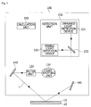
FIG. 1 is a view illustrating an apparatus for simultaneously measuring whiteness and a coating amount according to one embodiment of the present invention. -
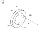
FIG. 2 is a view illustrating a filter unit according to one embodiment of the present invention. -
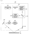
FIG. 3 is a view illustrating an apparatus for simultaneously measuring whiteness and a coating amount according to another embodiment of the present invention. - While the invention can be modified in various ways and take on various alternative forms, specific embodiments thereof are shown in the drawings and described in detail below as examples. However, it should be understood that there is no intent to limit the invention to the particular forms disclosed, but on the contrary, the invention covers all modifications, equivalents, and alternatives falling within the spirit and scope of the invention.
- It will be understood that, although the terms "first," "second," etc. may be used herein to describe various elements, these elements should not be limited by these terms. These terms are only used to distinguish one element from another. For example, a first element could be termed a second element, and a second element could similarly be termed a first element without departing from the scope of the present invention. As used herein, the term "and/or" includes any and all combinations of one or more of the associated listed items.
- It will be understood that when an element is referred to as being "connected" or "coupled" to another element, it can be directly connected or coupled to the other element or intervening elements may be present. In contrast, when an element is referred to as being "directly connected" or "directly coupled" to another element, there are no intervening elements.
- The terminology used herein to describe embodiments of the invention is not intended to limit the scope of the invention. The articles "a," and "an" are singular in that they have a single referent, however the use of the singular form in the present document should not preclude the presence of more than one referent. In other words, elements of the invention referred to in the singular may number one or more, unless the context clearly indicates otherwise. It will be further understood that the terms "comprise," "comprising," "include," and/or "including," when used herein, specify the presence of stated features, numbers, steps, operations, elements, and/or components but do not preclude the presence or addition of one or more other features, numbers, steps, operations, elements, components, and/or groups thereof.
- Unless otherwise defined, all terms (including technical and scientific terms) used herein are to be interpreted as is customary in the art to which this invention belongs. It will be further understood that terms in common usage should also be interpreted as is customary in the relevant art and not in an idealized or overly formal sense unless expressly so defined herein.
- Hereinafter, exemplary embodiments of the invention will be described in detail with reference to the accompanying drawings. The same or corresponding elements will be consistently denoted by the same respective reference numerals and described in detail no more than once regardless of drawing symbols.
-
FIG. 1 is a view illustrating an apparatus for simultaneously measuring whiteness and a coating amount according to one embodiment of the present invention, andFIG. 2 is a view illustrating a filter unit according to one embodiment of the present invention. - Referring to
FIGS. 1 to 2 , an apparatus for simultaneously measuring whiteness and acoating amount 100 according to one embodiment of the present invention includes a light-emitting unit 110, afilter unit 120, adetection unit 130, and acalculation unit 150. - The light-
emitting unit 110 is disposed to be spaced a predetermined distance from atest piece 10 and irradiates thetest piece 10 with light. Such a test piece 10 (hereinafter, a steel sheet) may be, for example, asteel sheet 10. To this end, the light-emittingunit 110 may include a light source which emits light in a predetermined wavelength region. Here, the predetermined wavelength region may include wavelength regions of infrared light and visible light. - The
filter unit 120 is disposed between the light-emittingunit 110 and thesteel sheet 10 and selectively transmits one of infrared light and visible light. For example, thefilter unit 120 may selectively transmit light in any one wavelength region of infrared light and visible light among light of predetermined wavelength regions emitted from thelight emitting unit 110. To this and, thefilter unit 120 may include aninfrared light filter 121 which transmits light in a wavelength region of infrared light and a visible light filter 122 which transmits light in a wavelength region of visible light. In addition, as illustrated inFIG. 2 , as thefilter unit 120 is rotatably disposed, thefilter unit 120 may be rotated so that any one of theinfrared light filter 121 and the visible light filter 122 is positioned in the path of light emitted from the light-emittingunit 110. - In addition, as illustrated in
FIG. 2 , thefilter unit 120 may include threevisible light filters filter unit 120 is not limited thereto and may include a plurality of visible light filters 122 which transmit visible light in wavelength regions different from each other within a wavelength region of the visible light. - The
detection unit 130 is disposed to be spaced a predetermined distance from thesteel sheet 10 and may detect one of infrared light and visible light reflected by thesteel sheet 10. To this end, thedetection unit 130 may include an infraredlight detection device 131 which detects infrared light and a visiblelight detection device 132 which detects visible light. - In addition, the
detection unit 130 may further include ahalf mirror 133. Such ahalf mirror 133 may transmit some of the incident light and reflect the rest. For example, thehalf mirror 133 may transmit some of the light reflected by thesteel sheet 10 to the infraredlight detection device 131 and reflect the rest to the visiblelight detection device 132. - The
calculation unit 150 is connected to thedetection unit 130, calculates a coating amount depending on an amount of infrared light detected by thedetection unit 130, and calculates whiteness depending on an amount of visible light detected by thedetection unit 130. For example, thecalculation unit 150 may calculate a coating amount of aresin 11 which coats thesteel sheet 10 depending on the amount of infrared light detected by the infraredlight detection device 131. In addition, thecalculation unit 150 may calculate whiteness of thesteel sheet 10 depending on the amount of visible light detected by the visiblelight detection device 132. -
FIG. 3 is a view illustrating an apparatus for simultaneously measuring whiteness and acoating amount 100 according to another embodiment of the present invention. - Referring to
FIG. 3 , an apparatus for simultaneously measuring whiteness and acoating amount 100 according to another embodiment of the present invention may further include afirst mirror 140 and asecond mirror 141. - The
first mirror 140 is disposed between afilter unit 120 and asteel sheet 10 and reflects light transmitted by thefilter unit 120 to thesteel sheet 10. In addition, thesecond mirror 141 is disposed between thesteel sheet 10 and adetection unit 130 and reflects light reflected by thesteel sheet 10 to ahalf mirror 133. Accordingly, since a path of light may be adjusted due to the apparatus for simultaneously measuring whiteness and acoating amount 100 according to another embodiment of the present invention including thefirst mirror 140 and thesecond mirror 141, the apparatus can be manufactured to have a smaller size. Accordingly, apparatus space occupancy can be reduced. - While the present invention has been described with reference to exemplary embodiments, it will be understood by those skilled in the art that various changes and modifications may be made without departing from the spirit and scope of the present invention as defined by the appended claims
-
- 10:
- TEST PIECE (STEEL SHEET)
- 11:
- RESIN COATING LAYER
- 100:
- APPARATUS FOR SIMULTANEOUSLY MEASURING WHITENESS AND COATING AMOUNT
- 110:
- LIGHT-EMITTING UNIT
- 120:
- FILTER UNIT
- 121:
- INFRARED LIGHT FILTER
- 122:
- VISIBLE LIGHT FILTER
- 130:
- DETECTION UNIT
- 131:
- INFRARED LIGHT DETECTION DEVICE
- 132:
- VISIBLE LIGHT DETECTION DEVICE
- 133:
- HALF MIRROR
- 140:
- FIRST MIRROR
- 141:
- SECOND MIRROR
- 150:
- CALCULATION UNIT
Claims (7)
- An apparatus for simultaneously measuring whiteness and a coating amount, comprising:a light-emitting unit which is disposed to be spaced a predetermined distance from a test piece and irradiates the test piece with light;a filter unit which is disposed between the light-emitting unit and the test piece and selectively transmits one of infrared light and visible light;a detection unit which is disposed to be spaced a predetermined distance from the test piece and detects one of infrared light and visible light reflected by the test piece; anda calculation unit which is connected to the detection unit, calculates a coating amount depending on an amount of infrared light detected by the detection unit, and calculates whiteness depending on an amount of visible light detected by the detection unit,
- The apparatus of claim 1, wherein the filter unit includes:at least one infrared light filter which transmits light in a wavelength region of infrared light; andat least one visible light filter which transmits light in a wavelength region of visible light.
- The apparatus of claim 2, wherein the filter unit is rotatably disposed and rotates such that any one of the infrared light filter and the visible light filter is disposed in a path of light emitted from the light-emitting unit.
- The apparatus of claim 2, wherein the filter unit includes a plurality of visible light filters which transmit light in wavelength regions different from each other in a wavelength region of visible light.
- The apparatus of claim 1, wherein the detection unit includes:an infrared light detection device which detects the infrared light; anda visible light detection device which detects the visible light.
- The apparatus of claim 5, wherein the detection unit further includes a half mirror, and the half mirror transmits some light reflected by the test piece to any one of the infrared light detection device and the visible light detection device and reflects the rest to the other.
- The apparatus of claim 1, further comprising:a first mirror which is disposed between a filter unit and a test piece and reflects light transmitted by the filter unit to the test piece; anda second mirror which is disposed between the test piece and a detection unit and reflects light reflected by the test piece to a half mirror.
Applications Claiming Priority (2)
| Application Number | Priority Date | Filing Date | Title |
|---|---|---|---|
| KR1020130163494A KR101614866B1 (en) | 2013-12-26 | 2013-12-26 | Simultaneous measurement apparatus of whiteness and coating weight |
| PCT/KR2013/012187 WO2015099227A1 (en) | 2013-12-26 | 2013-12-26 | Apparatus for simultaneously measuring whiteness and coating amount |
Publications (2)
| Publication Number | Publication Date |
|---|---|
| EP3088868A1 true EP3088868A1 (en) | 2016-11-02 |
| EP3088868A4 EP3088868A4 (en) | 2016-12-14 |
Family
ID=53479058
Family Applications (1)
| Application Number | Title | Priority Date | Filing Date |
|---|---|---|---|
| EP13900105.1A Withdrawn EP3088868A4 (en) | 2013-12-26 | 2013-12-26 | APPARATUS FOR SIMULTANEOUS MEASUREMENT OF WHITENESS AND QUANTITY OF COATING |
Country Status (6)
| Country | Link |
|---|---|
| US (1) | US20160320310A1 (en) |
| EP (1) | EP3088868A4 (en) |
| JP (1) | JP2017500576A (en) |
| KR (1) | KR101614866B1 (en) |
| CN (1) | CN105980834A (en) |
| WO (1) | WO2015099227A1 (en) |
Families Citing this family (1)
| Publication number | Priority date | Publication date | Assignee | Title |
|---|---|---|---|---|
| KR102175836B1 (en) * | 2018-10-10 | 2020-11-06 | 주식회사 포스코 | Post-treatment equipment for annealing line and control method thereof |
Family Cites Families (18)
| Publication number | Priority date | Publication date | Assignee | Title |
|---|---|---|---|---|
| JPS56108940A (en) * | 1980-02-04 | 1981-08-28 | Itouman Kk | Measuring device utilizing near infrared ray absorption |
| JPS61155714A (en) * | 1984-12-27 | 1986-07-15 | Kawasaki Steel Corp | Surface color tone control method and apparatus thereof |
| US4652757A (en) * | 1985-08-02 | 1987-03-24 | At&T Technologies, Inc. | Method and apparatus for optically determining defects in a semiconductor material |
| JP2705842B2 (en) * | 1989-09-26 | 1998-01-28 | 川崎製鉄株式会社 | Method and apparatus for measuring surface properties of metal plate |
| US7113619B1 (en) * | 1999-09-07 | 2006-09-26 | Fuji Photo Film Co., Ltd. | Image reading method, image reading apparatus and method of discriminating defect of image data |
| US6579783B2 (en) * | 2000-07-07 | 2003-06-17 | Applied Materials, Inc. | Method for high temperature metal deposition for reducing lateral silicidation |
| JP2002022652A (en) * | 2000-07-10 | 2002-01-23 | Horiba Ltd | Wavelength analysis type infrared image and visible image analyzer |
| DE10123470B4 (en) * | 2001-05-15 | 2010-08-19 | Carl Zeiss Jena Gmbh | Method and arrangement for non-contact determination of product properties |
| JP2004264077A (en) * | 2003-02-28 | 2004-09-24 | Jfe Steel Kk | Method for measuring coating amount, measuring device for coating amount, and reflection infrared absorption analyzer |
| JP4144389B2 (en) | 2003-03-14 | 2008-09-03 | オムロン株式会社 | Optical film measuring device |
| JP2004301672A (en) * | 2003-03-31 | 2004-10-28 | Nisshin Steel Co Ltd | Deposited film amount measuring instrument for inorganic/organic film-coated metallic material |
| JP2006153633A (en) * | 2004-11-29 | 2006-06-15 | Mitsubishi Electric Engineering Co Ltd | Flaw determining device of matter to be inspected |
| JP2007294604A (en) * | 2006-04-24 | 2007-11-08 | Tokyo Seimitsu Co Ltd | Appearance inspection apparatus and appearance inspection method |
| JP2008089486A (en) * | 2006-10-04 | 2008-04-17 | Jfe Steel Kk | Coating deposition amount measuring method |
| JP2011123019A (en) * | 2009-12-14 | 2011-06-23 | Olympus Corp | Image inspection apparatus |
| DE102010014744B4 (en) * | 2010-04-13 | 2013-07-11 | Siemens Aktiengesellschaft | Apparatus and method for projecting information onto an object in thermographic surveys |
| KR101206485B1 (en) * | 2010-12-28 | 2012-11-29 | 주식회사 포스코 | Whiteness measuring device and whiteness measuring method using the same |
| EP2530442A1 (en) * | 2011-05-30 | 2012-12-05 | Axis AB | Methods and apparatus for thermographic measurements. |
-
2013
- 2013-12-26 US US15/107,910 patent/US20160320310A1/en not_active Abandoned
- 2013-12-26 CN CN201380081681.2A patent/CN105980834A/en active Pending
- 2013-12-26 KR KR1020130163494A patent/KR101614866B1/en active Active
- 2013-12-26 JP JP2016542251A patent/JP2017500576A/en active Pending
- 2013-12-26 WO PCT/KR2013/012187 patent/WO2015099227A1/en not_active Ceased
- 2013-12-26 EP EP13900105.1A patent/EP3088868A4/en not_active Withdrawn
Also Published As
| Publication number | Publication date |
|---|---|
| US20160320310A1 (en) | 2016-11-03 |
| EP3088868A4 (en) | 2016-12-14 |
| KR20150076283A (en) | 2015-07-07 |
| CN105980834A (en) | 2016-09-28 |
| JP2017500576A (en) | 2017-01-05 |
| KR101614866B1 (en) | 2016-04-25 |
| WO2015099227A1 (en) | 2015-07-02 |
Similar Documents
| Publication | Publication Date | Title |
|---|---|---|
| JP2017521647A5 (en) | ||
| WO2008048244A3 (en) | Methods and apparatus for radar time sensor | |
| WO2011016892A3 (en) | Range imaging lidar | |
| US8970830B2 (en) | Measuring method and device for determining transmission and/or reflection properties | |
| EP3006891B1 (en) | Air spring with a distance measurement arrangement using infrared | |
| CA2798014A1 (en) | Methods and apparatus for dispensing solid articles | |
| EP2671044A1 (en) | Method and device for determining optical properties by simultaneous measurement of intensities at thin layers using light of several wavelengths | |
| TW200943006A (en) | Inspection method and apparatus, lithographic apparatus, lithographic processing cell and device manufacturing method | |
| WO2012019040A3 (en) | Spectrographic monitoring using index tracking after detection of layer clearing | |
| EP2741262A3 (en) | Door/window contact system | |
| WO2013072851A4 (en) | Pulse transponder countermeasure | |
| WO2009094608A3 (en) | Methods and apparatus for an integral local substrate center finder for i/o and chamber slit valves | |
| WO2012054263A3 (en) | Multiple matching reference spectra for in-situ optical monitoring | |
| US20160320310A1 (en) | Apparatus for simultaneously measuring whiteness and coating amount | |
| WO2010046896A3 (en) | Method and system for determining depth profiling | |
| CA2908964C (en) | Method and system for real-time in-process measurement of coating thickness | |
| WO2009057434A1 (en) | Mounting angle measuring device and mounting angle measuring method | |
| KR101434965B1 (en) | System and method for measuring thickness | |
| EP2566067A3 (en) | Method and apparatus for signal detection | |
| EP4174006B1 (en) | Elevator positioning system with cascading reflector arrangement | |
| JP2013104728A5 (en) | ||
| WO2011132038A3 (en) | Moving object detection system | |
| CN106706668A (en) | Method for long-term tracking and detecting of reflectivity performance of microwave absorbing coating | |
| WO2008152231A3 (en) | Method and device for monitoring a horizontal position of an aircraft rolling on the ground | |
| EP2749897A3 (en) | Method for searching for tag with communication error and electronic shelf label system server therefor |
Legal Events
| Date | Code | Title | Description |
|---|---|---|---|
| PUAI | Public reference made under article 153(3) epc to a published international application that has entered the european phase |
Free format text: ORIGINAL CODE: 0009012 |
|
| 17P | Request for examination filed |
Effective date: 20160621 |
|
| AK | Designated contracting states |
Kind code of ref document: A1 Designated state(s): AL AT BE BG CH CY CZ DE DK EE ES FI FR GB GR HR HU IE IS IT LI LT LU LV MC MK MT NL NO PL PT RO RS SE SI SK SM TR |
|
| AX | Request for extension of the european patent |
Extension state: BA ME |
|
| A4 | Supplementary search report drawn up and despatched |
Effective date: 20161110 |
|
| RIC1 | Information provided on ipc code assigned before grant |
Ipc: G01B 11/06 20060101ALI20161104BHEP Ipc: G01N 21/55 20060101ALI20161104BHEP Ipc: G01N 21/84 20060101ALI20161104BHEP Ipc: G01N 21/3563 20140101AFI20161104BHEP Ipc: G01N 21/25 20060101ALI20161104BHEP |
|
| DAX | Request for extension of the european patent (deleted) | ||
| STAA | Information on the status of an ep patent application or granted ep patent |
Free format text: STATUS: EXAMINATION IS IN PROGRESS |
|
| 17Q | First examination report despatched |
Effective date: 20200610 |
|
| STAA | Information on the status of an ep patent application or granted ep patent |
Free format text: STATUS: THE APPLICATION IS DEEMED TO BE WITHDRAWN |
|
| 18D | Application deemed to be withdrawn |
Effective date: 20201021 |