EP3088774A1 - Internal combustion engine - Google Patents
Internal combustion engine Download PDFInfo
- Publication number
- EP3088774A1 EP3088774A1 EP16166570.8A EP16166570A EP3088774A1 EP 3088774 A1 EP3088774 A1 EP 3088774A1 EP 16166570 A EP16166570 A EP 16166570A EP 3088774 A1 EP3088774 A1 EP 3088774A1
- Authority
- EP
- European Patent Office
- Prior art keywords
- piston
- cylinder liner
- inner periphery
- internal combustion
- combustion engine
- Prior art date
- Legal status (The legal status is an assumption and is not a legal conclusion. Google has not performed a legal analysis and makes no representation as to the accuracy of the status listed.)
- Withdrawn
Links
- 238000002485 combustion reaction Methods 0.000 title claims abstract description 100
- 230000006835 compression Effects 0.000 claims description 58
- 238000007906 compression Methods 0.000 claims description 58
- 230000007246 mechanism Effects 0.000 claims description 58
- 230000008859 change Effects 0.000 claims description 9
- 238000004519 manufacturing process Methods 0.000 claims description 4
- 239000003921 oil Substances 0.000 description 50
- 239000000446 fuel Substances 0.000 description 8
- 239000000567 combustion gas Substances 0.000 description 6
- 239000010720 hydraulic oil Substances 0.000 description 6
- 230000033001 locomotion Effects 0.000 description 6
- 230000008034 disappearance Effects 0.000 description 5
- 238000003780 insertion Methods 0.000 description 5
- 230000037431 insertion Effects 0.000 description 5
- 239000000203 mixture Substances 0.000 description 5
- 239000000498 cooling water Substances 0.000 description 2
- 230000006866 deterioration Effects 0.000 description 2
- 238000005461 lubrication Methods 0.000 description 2
- 230000000452 restraining effect Effects 0.000 description 2
- 230000000694 effects Effects 0.000 description 1
- 238000002347 injection Methods 0.000 description 1
- 239000007924 injection Substances 0.000 description 1
- 230000009467 reduction Effects 0.000 description 1
- 238000011160 research Methods 0.000 description 1
- 239000007787 solid Substances 0.000 description 1
- XLYOFNOQVPJJNP-UHFFFAOYSA-N water Substances O XLYOFNOQVPJJNP-UHFFFAOYSA-N 0.000 description 1
Images




Classifications
-
- F—MECHANICAL ENGINEERING; LIGHTING; HEATING; WEAPONS; BLASTING
- F02—COMBUSTION ENGINES; HOT-GAS OR COMBUSTION-PRODUCT ENGINE PLANTS
- F02F—CYLINDERS, PISTONS OR CASINGS, FOR COMBUSTION ENGINES; ARRANGEMENTS OF SEALINGS IN COMBUSTION ENGINES
- F02F5/00—Piston rings, e.g. associated with piston crown
-
- F—MECHANICAL ENGINEERING; LIGHTING; HEATING; WEAPONS; BLASTING
- F02—COMBUSTION ENGINES; HOT-GAS OR COMBUSTION-PRODUCT ENGINE PLANTS
- F02F—CYLINDERS, PISTONS OR CASINGS, FOR COMBUSTION ENGINES; ARRANGEMENTS OF SEALINGS IN COMBUSTION ENGINES
- F02F1/00—Cylinders; Cylinder heads
- F02F1/004—Cylinder liners
-
- F—MECHANICAL ENGINEERING; LIGHTING; HEATING; WEAPONS; BLASTING
- F02—COMBUSTION ENGINES; HOT-GAS OR COMBUSTION-PRODUCT ENGINE PLANTS
- F02B—INTERNAL-COMBUSTION PISTON ENGINES; COMBUSTION ENGINES IN GENERAL
- F02B75/00—Other engines
- F02B75/04—Engines with variable distances between pistons at top dead-centre positions and cylinder heads
-
- F—MECHANICAL ENGINEERING; LIGHTING; HEATING; WEAPONS; BLASTING
- F02—COMBUSTION ENGINES; HOT-GAS OR COMBUSTION-PRODUCT ENGINE PLANTS
- F02B—INTERNAL-COMBUSTION PISTON ENGINES; COMBUSTION ENGINES IN GENERAL
- F02B75/00—Other engines
- F02B75/04—Engines with variable distances between pistons at top dead-centre positions and cylinder heads
- F02B75/041—Engines with variable distances between pistons at top dead-centre positions and cylinder heads by means of cylinder or cylinderhead positioning
-
- F—MECHANICAL ENGINEERING; LIGHTING; HEATING; WEAPONS; BLASTING
- F02—COMBUSTION ENGINES; HOT-GAS OR COMBUSTION-PRODUCT ENGINE PLANTS
- F02B—INTERNAL-COMBUSTION PISTON ENGINES; COMBUSTION ENGINES IN GENERAL
- F02B75/00—Other engines
- F02B75/04—Engines with variable distances between pistons at top dead-centre positions and cylinder heads
- F02B75/045—Engines with variable distances between pistons at top dead-centre positions and cylinder heads by means of a variable connecting rod length
-
- F—MECHANICAL ENGINEERING; LIGHTING; HEATING; WEAPONS; BLASTING
- F16—ENGINEERING ELEMENTS AND UNITS; GENERAL MEASURES FOR PRODUCING AND MAINTAINING EFFECTIVE FUNCTIONING OF MACHINES OR INSTALLATIONS; THERMAL INSULATION IN GENERAL
- F16J—PISTONS; CYLINDERS; SEALINGS
- F16J10/00—Engine or like cylinders; Features of hollow, e.g. cylindrical, bodies in general
-
- F—MECHANICAL ENGINEERING; LIGHTING; HEATING; WEAPONS; BLASTING
- F16—ENGINEERING ELEMENTS AND UNITS; GENERAL MEASURES FOR PRODUCING AND MAINTAINING EFFECTIVE FUNCTIONING OF MACHINES OR INSTALLATIONS; THERMAL INSULATION IN GENERAL
- F16J—PISTONS; CYLINDERS; SEALINGS
- F16J9/00—Piston-rings, e.g. non-metallic piston-rings, seats therefor; Ring sealings of similar construction
- F16J9/12—Details
Definitions
- the present invention relates to an internal combustion engine.
- piston rings are arranged inside ring grooves formed in an outer periphery of the piston.
- An oil ring is the piston ring arranged at the lowest position among the piston rings. The oil ring is used to scrape off excessive oil adhered to a cylinder liner wall surface when the piston descends.
- JP 2012-241861 A a recessed portion is formed in a lower surface of a piston ring across the whole circumference. According to JP 2012-241861 A , when a movement direction of the piston is reversed at a top dead center, the piston ring moves towards an upper surface of a ring groove without being adhered to a lower surface of the ring groove. Therefore, it is possible to prevent oil inside the ring groove from flowing into the combustion chamber.
- an outer periphery of a top land of a piston and an inner periphery of a cylinder liner are arranged so as to face each other.
- the outer periphery of the top land of the piston and the inner periphery of the cylinder liner are positioned in a region where a flame does not propagate easily when air-fuel mixture is combusted inside a combustion chamber. Therefore, as the internal combustion engine is operated, deposits are formed on the outer periphery of the top land and the inner periphery of the cylinder liner, respectively.
- oil inside a crankcase moves towards a combustion chamber side along the outer periphery of the piston along with reciprocating motions of the piston.
- the oil that has moved to the combustion chamber side is adhered to the deposit formed on the outer periphery of the top land of the piston.
- the oil moves from the deposit formed on the outer periphery of the top land of the piston to the deposit formed on the inner periphery of the cylinder liner, which faces the top land.
- the oil adhered to the deposit formed on the inner periphery of the cylinder liner, which faces the top land is exposed to high temperature caused by combustion of air-fuel mixture inside the combustion chamber when the piston descends, and is evaporated. Thus, the oil is consumed.
- an object of the present invention is to provide an internal combustion engine that restrains oil consumption.
- an internal combustion engine includes a cylinder block, a cylinder liner, a piston, and a piston ring.
- the cylinder liner has a cylindrical shape, and is provided inside the cylinder block.
- the piston is positioned inside the cylinder liner.
- the piston includes a ring groove and a top land.
- the ring groove is positioned on an outer periphery of the piston in the vicinity of the top land.
- the piston ring is arranged inside the ring groove.
- the cylinder liner includes a first portion and a second portion.
- the first portion is positioned at least in a part of an inner periphery of the cylinder liner, which faces the top land of the piston when the piston is at a top dead center (or at a predetermined top end center in case where a variable compression ratio mechanism is used).
- the first portion includes a first inner periphery.
- the first inner periphery has a first radius.
- the second portion includes a second inner periphery.
- the second inner periphery has a second radius.
- the first radius is larger than the second radius by 100 ⁇ m to 1000 ⁇ m.
- a minimum difference between the first radius and the second radius may be 200 ⁇ m or more, more preferably 250 ⁇ m or more, and most preferably 300 ⁇ m or more.
- a maximum difference between the first radius and the second radius may be 800 ⁇ m or less, more preferably 600 ⁇ m or less, and most preferably 500 ⁇ m or less.
- the first portion may include a bottom surface extending from a lower end of the first inner periphery to a radially inner side of the cylinder liner, and the first portion may be defined by the bottom surface and the first inner periphery.
- the bottom surface may be at a position equal to or above an upper surface of the piston ring in an axial direction of the cylinder liner when the piston is at the top dead center.
- the bottom surface may be at a position equal to an upper surface of the ring groove in the axial direction of the cylinder liner when the piston is at the top dead center.
- the bottom surface of the first portion may be positioned above an upper surface of the ring groove in the axial direction of the cylinder liner by a predetermined margin when the piston is at the predetermined top dead center.
- the predetermined margin may be less than 1000 ⁇ m, preferably less than 500 ⁇ m.
- a position of the bottom surface may be lower than a position that is above an upper surface of the ring groove by 500 ⁇ m in the axial direction of the cylinder liner when the piston is at the top dead center.
- the internal combustion engine may further comprise a variable compression ratio mechanism.
- the variable compression ratio mechanism is configured to change a mechanical compression ratio by changing relative positions of the piston and the cylinder block in the axial direction of the cylinder liner when the piston is at a top dead center.
- the piston may be at the predetermined top dead center in a state where the mechanical compression ratio set by the variable compression ratio mechanism is the largest.
- the cylinder liner may include an upper marginal portion, a first connecting portion, and a second connecting portion.
- the upper marginal portion is located on the first inner periphery, and is an upper end part of the first inner periphery.
- the first inner periphery and the bottom surface is connected at the first connecting portion.
- the bottom surface and the second inner periphery is connected at the second connecting portion.
- At least one of the upper marginal portion, the first connecting portion, and the second connecting portion may be rounded or have a round shape.
- the first portion may extend to an upper surface of the cylinder liner.
- the upper surface and the first inner periphery may be connected at a first connecting portion
- the first inner periphery and the bottom surface may be connected at a second connecting portion
- the bottom surface and the second inner periphery may be connected at a third connecting portion.
- At least one of the first connecting portion, the second connecting portion, and the third connecting portion may be rounded or have a round shape.
- the cylinder liner has a cylindrical shape, and is provided inside the cylinder block.
- the piston is positioned inside the cylinder liner.
- the piston includes a ring groove and a top land.
- the ring groove is positioned on an outer periphery of the piston in the vicinity of the top land.
- the piston ring is arranged inside the ring groove.
- the cylinder liner includes a first portion and a second portion. The first portion is positioned at least in a part of an inner periphery of the cylinder liner, which faces the top land of the piston when the piston is at a top dead center.
- the first portion includes a first inner periphery.
- the first inner periphery has a first radius.
- the second portion includes a second inner periphery.
- the second inner periphery has a second radius.
- a distance between the first inner periphery and the second inner periphery in a radial direction of the cylinder liner (a difference of the first radius and the second radius) is set to be larger than a maximum accumulated height of a deposit that is expected to be accumulated on the first inner periphery during operation of the internal combustion engine, preferably during an operation time of at least 100 hours.
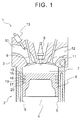
- FIG. 1 shows a partial sectional view of an internal combustion engine 1 to which this embodiment is applicable.
- the internal combustion engine 1 has a cylinder block 2 and a cylinder head 3.
- the cylinder head 3 is fixed to the cylinder block 2 through a gasket (not shown).
- the cylinder block 2 has a cylinder liner 5 having a cylindrical shape inside the cylinder block 2, and an inner periphery of the cylinder liner 5 defines a cylinder 4.
- a piston 6 is arranged inside the cylinder 4 such that the piston 6 is able to slide.
- the piston 6, the cylinder liner 5, and the cylinder head 3 form a combustion chamber 7, and an ignition plug 8 is arranged in a center part of a top face of the combustion chamber 7.
- An intake port 10 communicates with the combustion chamber 7, and an intake valve 9 is provided between the combustion chamber 7 and the intake port 10.
- an exhaust port 12 communicates with the combustion chamber 7, and an exhaust valve 11 is provided between the combustion chamber 7 and the exhaust port 12.
- a fuel injection valve 13 for injecting fuel is arranged inside the intake port 10.
- a plurality of ring grooves are provided, extending in the circumferential direction of the piston 6, and a piston ring is arranged in each of the ring grooves.
- three ring grooves are provided, which are separated from each other in an axial direction of the piston 6. Then, three piston rings are arranged around the piston 6.
- the piston rings are generally referred to as a top ring 18, a second ring 19, and an oil ring 20 from the top.
- a top land 15 a part above the ring groove in which the top ring 18 is arranged, is referred to as a top land 15.
- a part between the ring groove in which the top ring 18 is arranged, and the ring groove in which the second ring 19 is arranged is referred to as a second land 16.
- a part between the ring groove in which the second ring 19 is arranged, and the ring groove in which the oil ring 20 is arranged is referred to as a third land 17.
- a direction towards the combustion chamber 7 is regarded as an upper direction
- a direction opposite to the combustion chamber 7 side is regarded as a lower direction along the axis of the cylinder 4.
- the internal combustion engine is arranged so that the axis of the cylinder 4 extends vertically.
- An internal combustion engine having the above-mentioned structure has a problem that oil used for lubrication and so on is consumed by combustion.
- a mechanism causing this problem had not been clearly elucidated.
- the inventors have conducted intensive researches on this, and elucidated a part of the mechanism of the oil consumption.
- the mechanism of oil consumption is explained below with reference to FIG. 2 .
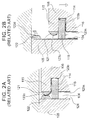
- FIG. 2A is a sectional view of upper parts of a piston 106 and a cylinder liner 105 when the piston 106 is at a top dead center in an internal combustion engine according to a related art.
- FIG. 2B is a sectional view of the upper parts of the piston 106 and the cylinder liner 105 when the piston 106 is located lower than the top dead center in the internal combustion engine shown in FIG. 2A .
- an outer periphery of a top land 115 positioned in the upper part of the piston 106 is structured so as to face an inner periphery of the cylinder liner 105.
- the outer periphery of the top land 115 and the inner periphery of the cylinder liner 105 are positioned in a region in which a flame does not propagate easily during combustion in the combustion chamber. Therefore, a deposit 121 is formed on the outer periphery of the top land 115. Further, a deposit 122 is formed on the inner periphery of the cylinder liner 105, which faces the outer periphery of the top land 115.
- the deposits are solid deposits generated due to imperfect combustion of fuel inside the combustion chamber.
- the position where the deposit 122 is formed is a position in the inner periphery of the cylinder liner 105, which faces the top land 115 when the piston 106 is at the top dead center.
- the deposit 121 formed on the outer periphery of the top land 115 grows gradually to a radially outer side of the piston 106 as the internal combustion engine is operated.
- the deposit 122 formed on the inner periphery of the cylinder liner 105 grows towards a radially inner side of the cylinder liner 105 as the internal combustion engine is operated.
- the deposits 121, 122 come into contact with each other when the piston 106 is at the top dead center.
- oil 123a (in FIG. 2A and FIG. 2B ) adhered onto the outer periphery of a second land 116 of the piston 106 moves upwardly along the outer periphery of the piston 106 due to inertia when the piston 106 descends.
- the top ring 118 moves inside a ring groove 114 so as to be in contact with an upper surface of the ring groove 114 as shown in FIG. 2B . Therefore, a gap is created between a lower surface of the ring groove 114 and a lower surface of the top ring 118.
- Oil 123b that has moved upwardly along the outer periphery of the second land 116 enters the ring groove 114 through the gap.
- the top ring 118 moves inside the ring groove 114 so as to be in contact with the lower surface of the ring groove 114 as shown in FIG. 2A .
- a gap is created between the upper surface of the ring groove 114 and an upper surface of the top ring 118.
- Oil accumulated inside the ring groove 114 moves upwardly through the gap onto the outer periphery of the top land 115.
- Oil 123c that has moved to the outer periphery of the top land 115 is adhered to the deposit 121 formed on the outer periphery of the top land 115.
- Oil 124 adhered onto the inner periphery of the cylinder liner 105 is basically scraped off by the top ring 118 as the piston 106 descends. Therefore, an amount of oil that moves upwardly along the cylinder liner 105 is extremely small. Thus, the amount of oil 124 that moves upwardly along the cylinder liner 105 is negligible compared to an amount of oil 123 that moves upwardly along the outer periphery of the piston 106.
- the deposit 121 is formed on the outer periphery of the top land 115 of the piston 106.
- the deposit 122 is formed on the inner periphery of the cylinder liner 105. Then, as growth of the deposits 121, 122 continues, the deposit 121 and the deposit 122 come into contact with each other every time the piston 106 reaches the top dead center. As the deposits 121, 122 come into contact with each other as stated above, a part of oil adhered to the deposit 121 moves onto the deposit 122.
- the deposit 122 formed on the inner periphery of the cylinder liner 105 is exposed to the combustion chamber as shown in FIG. 2B .
- the deposit 122 is exposed to high-temperature combustion gas. Therefore, oil 123d adhered to the deposit 122 is evaporated and disappears.
- the deposit 122 itself is not burnt and remains as it is. This is considered to be because heat applied to the deposit 122 escapes to the cylinder liner 105 at relatively low temperature.
- the contact between the deposit 121 and the deposit 122 is still repeated every time the piston 106 slides, and disappearance of the oil 123 continues.
- the deposit 121 formed on the outer periphery of the top land 115 gradually grows to the radially outer side of the piston 106 as the internal combustion engine is operated. Then, growth of the deposit 121 continues up until the deposit 121 reaches the inner periphery of the cylinder liner 105. When the deposit 121 grows and reaches the inner periphery of the cylinder liner 105, the growth is hindered by the inner periphery of the cylinder liner 105. Therefore, the deposit 121 is no longer able to grow any further.
- the deposit 122 formed on the inner periphery of the cylinder liner 105 also grows towards the radially inner side of the cylinder liner 105.
- the inventors found that, once reaching a certain height, the deposit 122 does not grow any further even though the deposit 122 does not reach the outer periphery of the top land of the piston 106. This is considered to be caused by the following mechanism.
- the cylinder liner 105 is cooled by cooling water flowing in a water jacket (not shown). Therefore, at an initial stage of growth of the deposit 122, even though the deposit 122 is exposed to high-temperature combustion gas, temperature of the deposit 122 does not become so high that would cause self-disappearance of the deposit 122 because the deposit 122 is cooled by the cooling water through the cylinder liner 105. However, since the deposit 122 has low thermal conductivity, when the deposit 122 grows, a portion away from the cylinder liner 105 is not cooled by the cylinder liner 105 sufficiently.
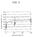
- FIG. 3 is view of a change of height of a deposit formed on an inner periphery of a cylinder liner with elapse of operation time.
- FIG. 3 shows results of plurality of tests conducted with each type of internal combustion engine. Different shapes of points in the drawing (triangle, quadrangle, and so on) mean types of internal combustion engines are different from each other.
- deposits formed on the inner peripheries of the cylinder liners grow rapidly to heights of about 100 ⁇ m to 200 ⁇ m in a short period of time after start of operation. Thereafter, after elapse of 100 hours of continuous operation, the deposits grow to heights of about 130 ⁇ m to 240 ⁇ m in most cases.
- the heights of the deposits are held at approximately 250 ⁇ m or lower in most of the internal combustion engines, and are also held at approximately 300 ⁇ m in almost all the internal combustion engines.
- An internal combustion engine 1 according to a first embodiment is structured in consideration of the foregoing mechanism of the oil consumption and the growth mechanism of deposits.
- the internal combustion engine 1 according to the first embodiment has an enlarged diameter part 30 in which a diameter of an inner periphery 5a of a cylinder liner 5 is enlarged.
- FIG. 4 is a sectional view of upper parts of a piston 6 and the cylinder liner 5 when the piston 6 is at a top dead center in the internal combustion engine 1 according to the first embodiment.
- the enlarged diameter part 30 is defined by an inner periphery 30a and a bottom surface 30b.
- the diameter of the inner periphery 30a is enlarged with respect to the inner periphery 5a of the cylinder liner 5.
- the bottom surface 30b is a surface extending to a radially inner side of a cylinder 4 from a lower end of the inner periphery 30a.
- the inner periphery 30a extends to an upper surface of the cylinder liner 5.
- a radius of the inner periphery 30a is larger than a radius of the inner periphery 5a by a radius enlargement dimension e.
- the radius enlargement dimension e is 100 ⁇ m or larger but not exceeding 1000 ⁇ m.
- the radius enlargement dimension e is preferably 200 ⁇ m or larger, more preferably 250 ⁇ m or larger, and most preferably 300 ⁇ m or larger.
- the radius enlargement dimension e is preferably 800 ⁇ m or smaller, more preferably 600 ⁇ m or smaller, and most preferably 500 ⁇ m or smaller.
- the bottom surface 30b is structured to be at a position equal to a position of an upper surface 14a of a ring groove 14 in an axial direction of the cylinder 4 when the piston 6 is at the top dead center.
- FIG. 5A and FIG. 5B are views of a state where deposits 21, 22 are formed on the piston 6 and the cylinder liner 5 shown in FIG. 4 .
- FIG. 5A is a sectional view when the piston 6 is at the top dead center.
- FIG. 5B is a sectional view when the piston 6 is positioned below the top dead center.
- the deposit 22 on the cylinder liner 5 is formed on the inner periphery 30a of the enlarged diameter part 30.
- the radius enlargement dimension e is set to 300 ⁇ m.
- the deposit 22 formed on the inner periphery 30a does not grow to a radially inner side up to the same plane as the inner periphery 5a.
- the deposit 21 on the outer periphery of the top land 15 does not grow to the radially outer side of the inner periphery 5a of the cylinder liner 5. Therefore, as shown in FIG. 5A , even when the piston 6 is at the top dead center, the deposit 21 does not come into contact with the deposit 22. Oil 23c adhered to the deposit 21 does not move to the deposit 22, which results in a reduction of disappearance of oil.
- the radius enlargement dimension e is set to a value larger than a maximum growing height of the deposit 22, namely a value within the numerical value range stated earlier.
- the radius enlargement dimension e is a value larger than 150 ⁇ m.
- the radius enlargement dimension e of the enlarged diameter part 30 should not be increased more than necessary.
- the radius enlargement dimension e is 1000 ⁇ m or smaller, preferably 800 ⁇ m or smaller, more preferably 600 ⁇ m or smaller, most preferably 500 ⁇ m or smaller.
- FIG. 6 is a sectional view of an internal combustion engine according to the first modified example of the first embodiment shown in FIG. 4 .
- Structures of a piston 6 and a cylinder liner 5 according to this modified example are basically similar to the structures of the piston 6 and the cylinder liner 5 according to the embodiment explained in FIG. 4 except the parts explained below.
- a bottom surface 230b of an enlarged diameter part 230 is structured so as to be at a position equal to an upper surface 18a of a top ring 18 in an axial direction of a cylinder 4 when the piston 6 is at a top dead center.
- the top ring 18 is able to slide to an uppermost end of an inner periphery 5a of the cylinder liner 5 as shown in FIG. 6 . Even if a deposit is formed in the vicinity of the uppermost end of the non-enlarged inner periphery 5a of the cylinder liner 5, it is possible to remove the deposit completely by the top ring 18.
- the position of the bottom surface 30b is equal to the position of the upper surface 14a of the ring groove 14 in the axial direction of the cylinder 4 when the piston 6 is at the top dead center.
- the position of the bottom surface 230b is equal to the position of the upper surface 18a of the top ring 18 in the axial direction of the cylinder 4 when the piston 6 is at the top dead center.
- the position of the bottom surface 230b is not limited to both of the positions.
- the position of the bottom surface 230b may be set to an arbitrary position between the position of the bottom surface 30b in the axial direction of the cylinder 4 shown in FIG.
- the position of the bottom surface 230b of the enlarged diameter part 230 is an arbitrary position in the axial direction in the cylinder 4 between the position of the upper surface 14a of the ring groove 14, and the position of the upper surface 18a of the top ring 18 when the piston 6 is at the top dead center.
- the position of the bottom surface 230b may be set slightly below the position of the upper surface 18a of the top ring 18. Therefore, the position of the bottom surface 230b of the enlarged diameter part 230 may be a position slightly lower than the position of the upper surface 14a of the ring groove 14 in the axial direction of the cylinder 4 when the piston 6 is at the top dead center.
- FIG. 7 is a sectional view of an internal combustion engine according to the second modified example of the first embodiment shown in FIG. 4 .
- Structures of a piston 6 and a cylinder liner 5 according to the second modified example are basically similar to the structures of the piston 6 and the cylinder liner 5 shown in FIG. 4 except for the parts explained below.
- the bottom surface 330b is structured so as to be positioned above a position of an upper surface 14a of a ring groove 14 in an axial direction of a cylinder 4 when the piston 6 is at a top dead center.
- the bottom surface 330b is structured so as to be positioned above the upper surface 14a of the ring groove 14 in the axial direction of the cylinder 4 by a margin M when the piston 6 is at the top dead center.
- the margin M is, for example, a value of 0 to 1000 ⁇ m, and preferably 0 to 500 ⁇ m.
- the bottom surface of the enlarged diameter part is structured so as to be at an arbitrary position between the position of the upper surface of the top ring 18 and the position higher than the upper surface 14a of the ring groove 14 by the margin M in the axial direction of the cylinder 4 when the piston 6 is at the top dead center.
- the enlarged diameter part is provided at least in a part of the inner periphery of the cylinder liner, which faces the top land 15, when the piston 6 is at the top dead center.
- a structure of an internal combustion engine 401 according to the second embodiment is basically similar to the structure of the internal combustion engine 1 according to the first embodiment explained in FIG. 4 except for the parts explained below.
- FIG. 8 is a sectional view of the internal combustion engine 401 having a variable compression ratio mechanism A.
- reference numeral 440 denotes a crankcase
- reference numeral 402 denotes a cylinder block.
- the internal combustion engine 401 according to the second embodiment has the variable compression ratio mechanism A that is able to change a mechanical compression ratio by changing a relative distance between the crankcase 440 and the cylinder block 402.
- FIG. 9 is an exploded perspective view of the variable compression ratio mechanism A shown in FIG. 8
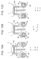
- FIG. 10A to FIG. 10C illustrate side sectional views of the internal combustion engine 401 shown in FIG. 8
- the variable compression ratio mechanism A is a mechanism for changing a volume of a combustion chamber 7 depending on a load of the internal combustion engine 401, thereby adjusting a mechanical compression ratio.
- a plurality of projecting parts 50 are formed so as to be separated from each other at intervals in lower parts of both side walls of the cylinder block 402 in a transverse direction.
- a circular cam insertion hole 51 is formed in each of the projecting parts 50.
- a plurality of projecting parts 52 are formed on an upper surface of the crankcase 440.
- the plurality of projecting parts 52 are arranged so as to be separated from each other at intervals.
- the plurality of projecting parts 52 are fitted between the corresponding projecting parts 50.
- a circular cam insertion hole 53 is provided in each of the plurality of projecting parts 52.
- the variable compression ratio mechanism A is provided with a pair of camshafts 54, 55.
- Circular cams 58 are fixed onto each of the camshafts 54, 55.
- the circular cams 58 are inserted into the cam insertion holes 53, respectively, so as to be able to rotate.
- the circular cams 58 are coaxial with a rotation axis of each of the camshafts 54, 55.
- an eccentric shaft 57 extends, which is eccentrically arranged with respect to the rotation axis of each of the camshafts 54, 55.
- Another circular cams 56 are eccentrically mounted on the eccentric shafts 57 so as to be able to rotate.
- these circular cams 56 are arranged alternately with the circular cams 58 in a camshaft longitudinal direction.
- the circular cams 56 are inserted into the corresponding cam insertion holes 51, respectively, so as to be able to rotate.
- FIG. 10A to FIG. 10C show a positional relationship among a center a of the circular cam 58, a center b of the eccentric shaft 57, and a center c of the circular cam 56 in the respective states.
- relative positions of the crankcase 440 and the cylinder block 402 are determined by a distance between the center a of the circular cams 58 and the center c of the circular cams 56. As the distance between the center a of the circular cams 58 and the center c of the circular cams 56 increases, the cylinder block 402 is separated more from the crankcase 440. This means that the variable compression ratio mechanism A changes relative positions of the crankcase 440 and the cylinder block 402 by a crank mechanism in which rotating cams are used. As the cylinder block 402 is separated from the crankcase 440, the volume of the combustion chamber 7 when the piston 6 is at the compression top dead center is increased.
- variable compression ratio mechanism A it is possible to change the relative positions of the piston 6 and the cylinder block 402 in the axial direction of the cylinder 4.
- the variable compression ratio mechanism A is also able to change a compression ratio of the internal combustion engine 401.
- variable compression ratio mechanism A shown in FIG. 9 , and FIG. 10A to FIG. 10C is just an example, any form of variable compression ratio mechanism may be used.
- FIG. 11A is a sectional view when the piston 6 is at the top dead center in the state shown in FIG. 10C , namely, in a state in which a compression ratio set by the variable compression ratio mechanism A becomes the largest.
- FIG. 11B is a sectional view showing a state where deposits are formed on the piston 6 and a cylinder liner 5 of the internal combustion engine shown in FIG. 11A .
- a bottom surface 430b is structured so as to be at a position equal to a position of an upper surface 14a of a ring groove 14 in an axial direction of a cylinder 4. Therefore, in the state where the compression ratio set by the variable compression ratio mechanism A is the lowest, the position of the bottom surface 430b becomes equal to the position of the upper surface 14a of the ring groove 14 in the axial direction of the cylinder 4 when the piston 6 is at the top dead center.
- the compression ratio set by the variable compression ratio mechanism A becomes the largest. As long as the compression ratio set by the variable compression ratio mechanism A is the largest, a deposit 21 on the piston 6 side and a deposit 22 on the cylinder liner 5 side do not come into contact with each other, like the foregoing first embodiment explained by using FIG. 5A . Therefore, oil does not move between the deposits 21, 22, thereby restraining disappearance of oil.
- FIG. 12 shows a case where a compression ratio set by the variable compression ratio mechanism A continues to be the smallest.
- FIG. 12 is a sectional view when the piston 6 is at the top dead center in the state shown in FIG. 10A , namely, a state in which the compression ratio set by the variable compression ratio mechanism A is the smallest.
- a deposit 25 could be formed on an inner periphery 5a of the cylinder liner 5, the diameter of which is not enlarged.
- the deposit 25 is formed on the inner periphery 5a of the cylinder liner 5 as shown in FIG.
- the position of the bottom surface 430b of the enlarged diameter part is equal to the position of the upper surface 14a of the ring groove 14 in the axial direction of the cylinder 4 in the state where the compression ratio set by the variable compression ratio mechanism A is the largest, and when the piston 6 is at the top dead center (also referred to as "predetermined top dead center").
- the position of the bottom surface 430b is not limited to this.
- FIG. 6 and FIG. 6 Like examples shown in FIG. 6 and FIG.
- the bottom surface 430b may be at an arbitrary position between a position of an upper surface 18a of a top ring 18 and a position higher than the upper surface 14a of the ring groove 14 by a margin M in the state where the compression ratio set by the variable compression ratio mechanism A is the largest and when the piston 6 is at the top dead center.
- the enlarged diameter part 430 only needs to be provided at least in a part of the inner periphery of the cylinder liner 5, which faces the top land 15 of the piston 6, in the state where the compression ratio set by the variable compression ratio mechanism A is the largest and when the piston 6 is at the top dead center.
- variable compression ratio mechanism A is used as a device that changes relative positions of the piston 6 and the cylinder block 2 when the piston 6 is at the top dead center.
- a device is not limited to this, and any device may be used as long as the device is able to change relative positions of the piston 6 and the cylinder block 2 when the piston 6 is at the top dead center.
- the effective length of the connecting rod means a distance between a center of a crank-receiving opening that receives a crank pin, and a center of a piston pin-receiving opening that receives the piston.
- the variable length connecting rod includes an eccentric member 32, a first piston mechanism 33, a second piston mechanism 34, and a flow direction changing mechanism 35.
- the eccentric member 32 is provided in a small-diameter end part of the body of the connecting rod so as to be able to pivot.
- the first piston mechanism 33 and the second piston mechanism 34 are provided in the body of the connecting rod.
- the flow direction changing mechanism 35 switches a flow of hydraulic oil towards the first piston mechanism 33 and the second piston mechanism 34.
- a receiving opening 32d for receiving a piston pin is provided in the eccentric member 32.
- the receiving opening 32d is eccentric to a rotation axis of the eccentric member 32.
- variable length connecting rod structured as above, a flow of hydraulic oil is switched by the flow direction changing mechanism 35 so that the hydraulic oil flows from the second piston mechanism 34 to the first piston mechanism 33.
- the eccentric member 32 turns in the direction shown by the arrow in FIG. 13A .
- the effective length of the connecting rod is increased (L1 in the drawing), and a compression ratio is increased.
- the flow direction changing mechanism 35 switches the flow of hydraulic oil so that the hydraulic oil flows from the first piston mechanism 33 to the second piston mechanism 34, the eccentric member 32 turns in the direction shown by the arrow in FIG. 13B .
- the effective length of the connecting rod becomes small (L2 in the drawing), and the compression ratio is reduced.
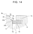
- FIG. 14 is a sectional view similar to FIG. 4 , showing an internal combustion engine according to a third embodiment.
- Structures of a piston 6 and a cylinder liner 5 according to this embodiment are basically similar to the structures of the piston 6 and the cylinder liner 5 according to the embodiment explained in FIG. 4 , except the parts explained below.
- a connecting part between an upper surface 5b and an inner periphery 30a with an enlarged diameter in a cylinder liner 5 have round shapes.
- a connecting part between the upper surface 5b of the cylinder liner 5 and the inner periphery 5a without the enlarged diameter, not between the upper surface 5b of the cylinder liner 5 and the inner periphery 30a with the enlarged diameter has a round shape.
- an upper edge part of the inner periphery 30a made by enlarging the diameter of the cylinder liner 5, the connecting part between the inner periphery 30a with the enlarged diameter and the bottom surface 30b, and the connecting part between the bottom surface 30b and the inner periphery 5a without the enlarged diameter, are all formed into round shapes.
- not all of them need to have round shapes, and the above-mentioned effects are obtained when at least one of them has a round shape.
- the cylinder liner 5 in this specification is a surface that defines the cylinder 4, and represents a part that has a surface on which the top ring 18 arranged in the piston 6 slides. Therefore, the cylinder liner 5 in this specification may be a cylinder body which is a separate body cast in a cylinder block 2, or may be an integral part of the cylinder block 2, which has an inner surface of a cylinder bore on which a sprayed film is formed.
- the height of the deposit 22 means a dimension of the deposit 22 in the direction perpendicular to the outer periphery of the piston 6 or the inner periphery 5a of the cylinder liner 5. Therefore, the height of the deposit 21 adhered onto the outer periphery of the piston 6 means a dimension from the outer periphery of the piston 6 to the outermost position of the deposit 21 in the radial direction of the cylinder 4. Similarly, the height of the deposit 22 adhered to the inner periphery 5a of the cylinder liner 5 means a dimension from the inner periphery 5a of the cylinder liner 5 to the innermost position of the deposit 22 in the radial direction of the cylinder 4.
Landscapes
- Engineering & Computer Science (AREA)
- General Engineering & Computer Science (AREA)
- Mechanical Engineering (AREA)
- Chemical & Material Sciences (AREA)
- Combustion & Propulsion (AREA)
- Cylinder Crankcases Of Internal Combustion Engines (AREA)
- Pistons, Piston Rings, And Cylinders (AREA)
- Output Control And Ontrol Of Special Type Engine (AREA)
Abstract
An internal combustion engine includes a cylinder block (2), a cylinder liner (5), a piston (6), and a piston ring (18). The cylinder liner (5) has a cylindrical shape, and is provided inside the cylinder block (2). The piston (6) is positioned inside the cylinder liner (5). The piston (6) includes a ring groove (14) and a top land (15). The ring groove (14) is positioned on an outer periphery of the piston (6) in the vicinity of the top land (15). The piston ring (18) is arranged inside the ring groove (14). The cylinder liner (5) includes a first portion (30) and a second portion. The first portion (30) is positioned at least in a part of an inner periphery (5a) of the cylinder liner (5), which faces the top land (15) of the piston (6) when the piston (6) is at a top dead center. The first portion (30) includes a first inner periphery (30a). The first inner periphery (30a) has a first radius. The second portion includes a second inner periphery (5a). The second inner periphery (5a) has a second radius. The first radius is larger than the second radius by 100 µm to 1000 µm.
Description
- The present invention relates to an internal combustion engine.
- In a piston of an internal combustion engine, piston rings are arranged inside ring grooves formed in an outer periphery of the piston. An oil ring is the piston ring arranged at the lowest position among the piston rings. The oil ring is used to scrape off excessive oil adhered to a cylinder liner wall surface when the piston descends.
- However, it is known that, in many internal combustion engines, oil in a crankcase flows into a combustion chamber even though the oil ring is used. Oil flows into the combustion chamber through an outer periphery of a piston, especially inside of the ring grooves, along with reciprocating motions of the piston. When oil in the crankcase flows into the combustion chamber, oil is burnt along with combustion inside the combustion chamber, thereby increasing oil consumption.
- Thus, in Japanese Patent Application Publication
JP 2012-241861 A JP 2012-241861 A - It is considered that oil consumption happens in the following mechanism. First of all, an outer periphery of a top land of a piston and an inner periphery of a cylinder liner are arranged so as to face each other. The outer periphery of the top land of the piston and the inner periphery of the cylinder liner are positioned in a region where a flame does not propagate easily when air-fuel mixture is combusted inside a combustion chamber. Therefore, as the internal combustion engine is operated, deposits are formed on the outer periphery of the top land and the inner periphery of the cylinder liner, respectively. As the amounts of deposits grow, the deposit formed on the outer periphery of the top land, and the deposit formed on the inner periphery of the cylinder liner, which faces the outer periphery of the top land, come into contact with each other when the piston is at the top dead center.
- Meanwhile, as stated above, in an internal combustion engine, oil inside a crankcase moves towards a combustion chamber side along the outer periphery of the piston along with reciprocating motions of the piston. The oil that has moved to the combustion chamber side is adhered to the deposit formed on the outer periphery of the top land of the piston. Thereafter, when the deposits are in contact with each other, the oil moves from the deposit formed on the outer periphery of the top land of the piston to the deposit formed on the inner periphery of the cylinder liner, which faces the top land. The oil adhered to the deposit formed on the inner periphery of the cylinder liner, which faces the top land, is exposed to high temperature caused by combustion of air-fuel mixture inside the combustion chamber when the piston descends, and is evaporated. Thus, the oil is consumed.
- Therefore, an object of the present invention is to provide an internal combustion engine that restrains oil consumption.
- According to one embodiment of the present invention, an internal combustion engine includes a cylinder block, a cylinder liner, a piston, and a piston ring. The cylinder liner has a cylindrical shape, and is provided inside the cylinder block. The piston is positioned inside the cylinder liner. The piston includes a ring groove and a top land. The ring groove is positioned on an outer periphery of the piston in the vicinity of the top land. The piston ring is arranged inside the ring groove. The cylinder liner includes a first portion and a second portion. The first portion is positioned at least in a part of an inner periphery of the cylinder liner, which faces the top land of the piston when the piston is at a top dead center (or at a predetermined top end center in case where a variable compression ratio mechanism is used). The first portion includes a first inner periphery. The first inner periphery has a first radius. The second portion includes a second inner periphery. The second inner periphery has a second radius. The first radius is larger than the second radius by 100 µm to 1000 µm.
- According to an embodiment of the present invention, a minimum difference between the first radius and the second radius may be 200 µm or more, more preferably 250 µm or more, and most preferably 300 µm or more. In addition, a maximum difference between the first radius and the second radius may be 800 µm or less, more preferably 600 µm or less, and most preferably 500 µm or less.
- According to an aspect of the present invention, the first portion may include a bottom surface extending from a lower end of the first inner periphery to a radially inner side of the cylinder liner, and the first portion may be defined by the bottom surface and the first inner periphery. The bottom surface may be at a position equal to or above an upper surface of the piston ring in an axial direction of the cylinder liner when the piston is at the top dead center.
- According to an aspect of the present invention, the bottom surface may be at a position equal to an upper surface of the ring groove in the axial direction of the cylinder liner when the piston is at the top dead center.
- According to an aspect of the present invention, the bottom surface of the first portion may be positioned above an upper surface of the ring groove in the axial direction of the cylinder liner by a predetermined margin when the piston is at the predetermined top dead center.
- According to an aspect of the present invention, the predetermined margin may be less than 1000 µm, preferably less than 500 µm.
- According to an aspect of the present invention, a position of the bottom surface may be lower than a position that is above an upper surface of the ring groove by 500 µm in the axial direction of the cylinder liner when the piston is at the top dead center.
- According to an aspect of the present invention, the internal combustion engine may further comprise a variable compression ratio mechanism. The variable compression ratio mechanism is configured to change a mechanical compression ratio by changing relative positions of the piston and the cylinder block in the axial direction of the cylinder liner when the piston is at a top dead center. The piston may be at the predetermined top dead center in a state where the mechanical compression ratio set by the variable compression ratio mechanism is the largest.
- According to an aspect of the present invention, the cylinder liner may include an upper marginal portion, a first connecting portion, and a second connecting portion. The upper marginal portion is located on the first inner periphery, and is an upper end part of the first inner periphery. The first inner periphery and the bottom surface is connected at the first connecting portion. The bottom surface and the second inner periphery is connected at the second connecting portion. At least one of the upper marginal portion, the first connecting portion, and the second connecting portion may be rounded or have a round shape.
- According to an aspect of the present invention, the first portion may extend to an upper surface of the cylinder liner. The upper surface and the first inner periphery may be connected at a first connecting portion, the first inner periphery and the bottom surface may be connected at a second connecting portion, and the bottom surface and the second inner periphery may be connected at a third connecting portion. At least one of the first connecting portion, the second connecting portion, and the third connecting portion may be rounded or have a round shape.
- Another aspect of the present invention relates to a manufacturing method of an internal combustion engine that includes a cylinder block, a cylinder liner, a piston, and a piston ring. The cylinder liner has a cylindrical shape, and is provided inside the cylinder block. The piston is positioned inside the cylinder liner. The piston includes a ring groove and a top land. The ring groove is positioned on an outer periphery of the piston in the vicinity of the top land. The piston ring is arranged inside the ring groove. The cylinder liner includes a first portion and a second portion. The first portion is positioned at least in a part of an inner periphery of the cylinder liner, which faces the top land of the piston when the piston is at a top dead center. The first portion includes a first inner periphery. The first inner periphery has a first radius. The second portion includes a second inner periphery. The second inner periphery has a second radius. According to the manufacturing method of the present invention, a distance between the first inner periphery and the second inner periphery in a radial direction of the cylinder liner (a difference of the first radius and the second radius) is set to be larger than a maximum accumulated height of a deposit that is expected to be accumulated on the first inner periphery during operation of the internal combustion engine, preferably during an operation time of at least 100 hours.
- It is possible to provide an internal combustion engine that is able to restrain oil consumption in consideration of the mechanism of oil consumption.
- Features, advantages, and technical and industrial significance of exemplary embodiments will be described below with reference to the accompanying drawings, in which like numerals denote like elements, and wherein:
-
FIG. 1 is a partial sectional view of an internal combustion engine; -
FIG. 2A is a sectional view of upper parts of a piston and a cylinder liner when the piston is at a top dead center in an internal combustion engine according to a related art, andFIG. 2B is a sectional view of upper parts of the piston and the cylinder liner when the piston is located lower than the top dead center in the internal combustion engine shown inFIG. 2A ; -
FIG. 3 is a view of a change of height of a deposit formed on an inner periphery of a cylinder liner in each type of internal combustion engine with elapse of operation time; -
FIG. 4 is a sectional view of upper parts of a piston and a cylinder liner when the piston is at a top dead center in an internal combustion engine according to a first embodiment of the present invention; -
FIG. 5A is a sectional view of the upper parts of the piston and the cylinder liner when the piston is at the top dead center in a state where deposits are formed on the piston and the cylinder liner, andFIG. 5B is a sectional view when the piston shown inFIG. 5A is located lower than the top dead center; -
FIG. 6 is a sectional view of upper parts of a piston and a cylinder liner when the piston is at a top dead center in an internal combustion engine according to first modified example of the first embodiment of the present invention; -
FIG. 7 is a sectional view similar toFIG. 4 , showing upper parts of a piston and a cylinder liner when the piston is at a top dead center in an internal combustion engine according to a second modified example of the first embodiment of the present invention; -
FIG. 8 is a partial sectional view similar toFIG. 1 , showing an internal combustion engine according to the second embodiment of the present invention, which has a variable compression ratio mechanism; -
FIG. 9 is an exploded perspective view of the variable compression ratio mechanism shown inFIG. 8 ; -
FIG. 10A to FIG. 10C are side sectional views illustrating movements of the internal combustion engine shown inFIG. 8 ; -
FIG. 11A is a sectional view similar toFIG. 4 , when a piston is at the top dead center in a state where a mechanical compression ratio is maximized, andFIG. 11B is a sectional view of a state where deposits are formed on the piston and the cylinder liner of the internal combustion engine shown inFIG. 11A ; -
FIG. 12 is a sectional view when the piston is at the top dead center in a state shown inFIG. 10A , namely, in a state where a compression ratio by the variable compression ratio mechanism is minimized; -
FIG. 13A and FIG. 13B are schematic sectional side views of a variable length connecting rod; and -
FIG. 14 is a sectional view similar toFIG. 4 , showing an internal combustion engine according to a third embodiment of the present invention. - Embodiments are explained below in detail with reference to the drawings. Components corresponding to each other are denoted by common reference numerals throughout the drawings.
-
FIG. 1 shows a partial sectional view of aninternal combustion engine 1 to which this embodiment is applicable. Theinternal combustion engine 1 has acylinder block 2 and acylinder head 3. Thecylinder head 3 is fixed to thecylinder block 2 through a gasket (not shown). Thecylinder block 2 has acylinder liner 5 having a cylindrical shape inside thecylinder block 2, and an inner periphery of thecylinder liner 5 defines acylinder 4. Apiston 6 is arranged inside thecylinder 4 such that thepiston 6 is able to slide. Thepiston 6, thecylinder liner 5, and thecylinder head 3 form acombustion chamber 7, and anignition plug 8 is arranged in a center part of a top face of thecombustion chamber 7. Anintake port 10 communicates with thecombustion chamber 7, and anintake valve 9 is provided between thecombustion chamber 7 and theintake port 10. Similarly, anexhaust port 12 communicates with thecombustion chamber 7, and anexhaust valve 11 is provided between thecombustion chamber 7 and theexhaust port 12. Afuel injection valve 13 for injecting fuel is arranged inside theintake port 10. - In an outer periphery of the
piston 6, a plurality of ring grooves are provided, extending in the circumferential direction of thepiston 6, and a piston ring is arranged in each of the ring grooves. In this embodiment, in the outer periphery of thepiston 6, three ring grooves are provided, which are separated from each other in an axial direction of thepiston 6. Then, three piston rings are arranged around thepiston 6. The piston rings are generally referred to as atop ring 18, asecond ring 19, and anoil ring 20 from the top. In thepiston 6, a part above the ring groove in which thetop ring 18 is arranged, is referred to as atop land 15. Also, in thepiston 6, a part between the ring groove in which thetop ring 18 is arranged, and the ring groove in which thesecond ring 19 is arranged, is referred to as asecond land 16. In addition, in thepiston 6, a part between the ring groove in which thesecond ring 19 is arranged, and the ring groove in which theoil ring 20 is arranged, is referred to as athird land 17. In the explanation, a direction towards thecombustion chamber 7 is regarded as an upper direction, and a direction opposite to thecombustion chamber 7 side is regarded as a lower direction along the axis of thecylinder 4. However, it is not always necessary that the internal combustion engine is arranged so that the axis of thecylinder 4 extends vertically. - An internal combustion engine having the above-mentioned structure has a problem that oil used for lubrication and so on is consumed by combustion. However, a mechanism causing this problem had not been clearly elucidated. The inventors have conducted intensive researches on this, and elucidated a part of the mechanism of the oil consumption. The mechanism of oil consumption is explained below with reference to
FIG. 2 . -
FIG. 2A is a sectional view of upper parts of apiston 106 and acylinder liner 105 when thepiston 106 is at a top dead center in an internal combustion engine according to a related art.FIG. 2B is a sectional view of the upper parts of thepiston 106 and thecylinder liner 105 when thepiston 106 is located lower than the top dead center in the internal combustion engine shown inFIG. 2A . - In the internal combustion engine according to the related art shown in
FIG. 2A and FIG. 2B , an outer periphery of atop land 115 positioned in the upper part of thepiston 106 is structured so as to face an inner periphery of thecylinder liner 105. The outer periphery of thetop land 115 and the inner periphery of thecylinder liner 105 are positioned in a region in which a flame does not propagate easily during combustion in the combustion chamber. Therefore, adeposit 121 is formed on the outer periphery of thetop land 115. Further, adeposit 122 is formed on the inner periphery of thecylinder liner 105, which faces the outer periphery of thetop land 115. The deposits are solid deposits generated due to imperfect combustion of fuel inside the combustion chamber. - However, out of the inner periphery of the
cylinder liner 105, no deposit is basically formed on the inner periphery positioned lower than an upper surface of atop ring 118 when thepiston 106 is at the top dead center. This is because, even though a deposit is adhered, the deposit is scraped off by thetop ring 118 when thepiston 106 slides. As shown inFIG. 2A , the position where thedeposit 122 is formed is a position in the inner periphery of thecylinder liner 105, which faces thetop land 115 when thepiston 106 is at the top dead center. - The
deposit 121 formed on the outer periphery of thetop land 115 grows gradually to a radially outer side of thepiston 106 as the internal combustion engine is operated. Similarly, thedeposit 122 formed on the inner periphery of thecylinder liner 105 grows towards a radially inner side of thecylinder liner 105 as the internal combustion engine is operated. As growth of thedeposits deposits piston 106 is at the top dead center. - Next, movements of oil inside the
cylinder 104 is explained. For the purpose of lubrication and so on between the sliding piston ring and thecylinder liner 105, oil is supplied into thecylinder 104 in which thepiston 106 is arranged. In particular, oil adhered onto the outer periphery of thepiston 106 moves upwardly along the outer periphery of thepiston 106 due to reciprocating motions of thepiston 106. - Specifically,
oil 123a (inFIG. 2A and FIG. 2B ) adhered onto the outer periphery of asecond land 116 of thepiston 106 moves upwardly along the outer periphery of thepiston 106 due to inertia when thepiston 106 descends. At that time, thetop ring 118 moves inside aring groove 114 so as to be in contact with an upper surface of thering groove 114 as shown inFIG. 2B . Therefore, a gap is created between a lower surface of thering groove 114 and a lower surface of thetop ring 118.Oil 123b that has moved upwardly along the outer periphery of thesecond land 116 enters thering groove 114 through the gap. - Thereafter, as the
piston 106 ascends, thetop ring 118 moves inside thering groove 114 so as to be in contact with the lower surface of thering groove 114 as shown inFIG. 2A . Thus, a gap is created between the upper surface of thering groove 114 and an upper surface of thetop ring 118. Oil accumulated inside thering groove 114 moves upwardly through the gap onto the outer periphery of thetop land 115.Oil 123c that has moved to the outer periphery of thetop land 115 is adhered to thedeposit 121 formed on the outer periphery of thetop land 115. -
Oil 124 adhered onto the inner periphery of thecylinder liner 105 is basically scraped off by thetop ring 118 as thepiston 106 descends. Therefore, an amount of oil that moves upwardly along thecylinder liner 105 is extremely small. Thus, the amount ofoil 124 that moves upwardly along thecylinder liner 105 is negligible compared to an amount of oil 123 that moves upwardly along the outer periphery of thepiston 106. - As stated above, the
deposit 121 is formed on the outer periphery of thetop land 115 of thepiston 106. Thedeposit 122 is formed on the inner periphery of thecylinder liner 105. Then, as growth of thedeposits deposit 121 and thedeposit 122 come into contact with each other every time thepiston 106 reaches the top dead center. As thedeposits deposit 121 moves onto thedeposit 122. - Thereafter, as the
piston 106 descends, thedeposit 122 formed on the inner periphery of thecylinder liner 105 is exposed to the combustion chamber as shown inFIG. 2B . At this time, although unlikely to be exposed to flame, thedeposit 122 is exposed to high-temperature combustion gas. Therefore,oil 123d adhered to thedeposit 122 is evaporated and disappears. Meanwhile, being exposed to high-temperature combustion gas, thedeposit 122 itself is not burnt and remains as it is. This is considered to be because heat applied to thedeposit 122 escapes to thecylinder liner 105 at relatively low temperature. Thus, the contact between thedeposit 121 and thedeposit 122 is still repeated every time thepiston 106 slides, and disappearance of the oil 123 continues. - Even though the
deposits deposit 121 formed on the outer periphery of thetop land 115. Theoil 123c remaining on thedeposit 121 is rarely evaporated by high-temperature combustion gas in the combustion chamber when thepiston 106 descends. This is considered to be because, even though combustion happens, temperature in a space between the outer periphery of thetop land 115 and the inner periphery of thecylinder liner 105 does not become so high that theoil 123c would be evaporated. Since this space is narrow and surrounded by thepiston 106 and thecylinder liner 105 at low temperature, it is considered unlikely that temperature becomes high. Further, since the outer periphery of thetop land 115 of thedescending piston 106 is unlikely to be exposed to high-temperature combustion gas, it is considered that theoil 123c is rarely evaporated. Therefore,oil 123d disappears solely on thedeposit 122 formed on the inner periphery of thecylinder liner 105. - As stated above, the
deposit 121 formed on the outer periphery of thetop land 115 gradually grows to the radially outer side of thepiston 106 as the internal combustion engine is operated. Then, growth of thedeposit 121 continues up until thedeposit 121 reaches the inner periphery of thecylinder liner 105. When thedeposit 121 grows and reaches the inner periphery of thecylinder liner 105, the growth is hindered by the inner periphery of thecylinder liner 105. Therefore, thedeposit 121 is no longer able to grow any further. - The
deposit 122 formed on the inner periphery of thecylinder liner 105 also grows towards the radially inner side of thecylinder liner 105. The inventors found that, once reaching a certain height, thedeposit 122 does not grow any further even though thedeposit 122 does not reach the outer periphery of the top land of thepiston 106. This is considered to be caused by the following mechanism. - The
cylinder liner 105 is cooled by cooling water flowing in a water jacket (not shown). Therefore, at an initial stage of growth of thedeposit 122, even though thedeposit 122 is exposed to high-temperature combustion gas, temperature of thedeposit 122 does not become so high that would cause self-disappearance of thedeposit 122 because thedeposit 122 is cooled by the cooling water through thecylinder liner 105. However, since thedeposit 122 has low thermal conductivity, when thedeposit 122 grows, a portion away from thecylinder liner 105 is not cooled by thecylinder liner 105 sufficiently. Thus, when thedeposit 122 grows to a certain height or above, surface temperature of thedeposit 122 becomes so high in a region at the certain height or above that causes self-disappearance of thedeposit 122. As stated above, thedeposit 122 formed to the certain height or above is exposed to high-temperature combustion gas inside the combustion chamber, and disappears by itself. As a result, it is considered that thedeposit 122 formed on thecylinder liner 105 does not grow to the certain height or above. - It was confirmed by the studies conducted by the inventors that, although slightly varied depending on conductions, the certain height of the
deposit 122 was between 130 and 250 µm. This is explained by usingFIG. 3 . -
FIG. 3 is view of a change of height of a deposit formed on an inner periphery of a cylinder liner with elapse of operation time.FIG. 3 shows results of plurality of tests conducted with each type of internal combustion engine. Different shapes of points in the drawing (triangle, quadrangle, and so on) mean types of internal combustion engines are different from each other. As seen inFIG. 3 , in most cases, deposits formed on the inner peripheries of the cylinder liners grow rapidly to heights of about 100 µm to 200 µm in a short period of time after start of operation. Thereafter, after elapse of 100 hours of continuous operation, the deposits grow to heights of about 130 µm to 240 µm in most cases. However, there is no major changes thereafter, and the heights of the deposits are held at approximately 250 µm or lower in most of the internal combustion engines, and are also held at approximately 300 µm in almost all the internal combustion engines. - An
internal combustion engine 1 according to a first embodiment is structured in consideration of the foregoing mechanism of the oil consumption and the growth mechanism of deposits. As shown inFIG. 4 , theinternal combustion engine 1 according to the first embodiment has anenlarged diameter part 30 in which a diameter of aninner periphery 5a of acylinder liner 5 is enlarged.FIG. 4 is a sectional view of upper parts of apiston 6 and thecylinder liner 5 when thepiston 6 is at a top dead center in theinternal combustion engine 1 according to the first embodiment. - The
enlarged diameter part 30 is defined by aninner periphery 30a and abottom surface 30b. The diameter of theinner periphery 30a is enlarged with respect to theinner periphery 5a of thecylinder liner 5. Thebottom surface 30b is a surface extending to a radially inner side of acylinder 4 from a lower end of theinner periphery 30a. In this embodiment, theinner periphery 30a extends to an upper surface of thecylinder liner 5. A radius of theinner periphery 30a is larger than a radius of theinner periphery 5a by a radius enlargement dimension e. In this embodiment, the radius enlargement dimension e is 100 µm or larger but not exceeding 1000 µm. The radius enlargement dimension e is preferably 200 µm or larger, more preferably 250 µm or larger, and most preferably 300 µm or larger. In addition, the radius enlargement dimension e is preferably 800 µm or smaller, more preferably 600 µm or smaller, and most preferably 500 µm or smaller. - In this embodiment, the
bottom surface 30b is structured to be at a position equal to a position of anupper surface 14a of aring groove 14 in an axial direction of thecylinder 4 when thepiston 6 is at the top dead center. -
FIG. 5A and FIG. 5B are views of a state wheredeposits piston 6 and thecylinder liner 5 shown inFIG. 4 .FIG. 5A is a sectional view when thepiston 6 is at the top dead center.FIG. 5B is a sectional view when thepiston 6 is positioned below the top dead center. As shown inFIG. 5A , thedeposit 22 on thecylinder liner 5 is formed on theinner periphery 30a of theenlarged diameter part 30. As stated earlier, once thedeposit 22 grows to a certain height, thedeposit 22 does not grow any further. Therefore, for example, in a case of an internal combustion engine in which thedeposit 22 grows up to 280 µm, the radius enlargement dimension e is set to 300 µm. Then, thedeposit 22 formed on theinner periphery 30a does not grow to a radially inner side up to the same plane as theinner periphery 5a. - As stated earlier, the
deposit 21 on the outer periphery of thetop land 15 does not grow to the radially outer side of theinner periphery 5a of thecylinder liner 5. Therefore, as shown inFIG. 5A , even when thepiston 6 is at the top dead center, thedeposit 21 does not come into contact with thedeposit 22.Oil 23c adhered to thedeposit 21 does not move to thedeposit 22, which results in a reduction of disappearance of oil. - As stated above, unless the
deposit 21 on thepiston 6 side and thedeposit 22 on thecylinder liner 5 side are in contact with each other, it is possible to reduce disappearance of oil. Therefore, in this embodiment, even though thedeposit 22 is adhered to theinner periphery 30a, theinner periphery 30a of theenlarged diameter part 30 is provided so that thedeposit 22 does not grow on the radially inner side of theinner periphery 5a. This means that the radius enlargement dimension e is set to a value larger than a maximum growing height of thedeposit 22, namely a value within the numerical value range stated earlier. Hence, for example, in a case where the maximum height of thedeposit 22 formed on the inner periphery of thecylinder liner 5 is 150 µm, the radius enlargement dimension e is a value larger than 150 µm. - In a case of a gasoline engine, it is unlikely that air-fuel mixture that has entered the
enlarged diameter part 30 contributes to initial combustion. Therefore, as theenlarged diameter part 30 is increased, deterioration of combustion of the air-fuel mixture inside thecombustion chamber 7 is caused. Therefore, the radius enlargement dimension e of theenlarged diameter part 30 should not be increased more than necessary. In a case of a diesel engine, since theenlarged diameter part 30 becomes an unnecessary volume in which air enters, the radius enlargement dimension e should not be increased more than necessary. Because of these reasons, in this embodiment, it is preferred that the radius enlargement dimension e is 1000 µm or smaller, preferably 800 µm or smaller, more preferably 600 µm or smaller, most preferably 500 µm or smaller. Thus, it is possible to minimize deterioration of combustion of air-fuel mixture caused by provision of theenlarged diameter part 30. -
FIG. 6 is a sectional view of an internal combustion engine according to the first modified example of the first embodiment shown inFIG. 4 . Structures of apiston 6 and acylinder liner 5 according to this modified example are basically similar to the structures of thepiston 6 and thecylinder liner 5 according to the embodiment explained inFIG. 4 except the parts explained below. - In this modified example, a
bottom surface 230b of anenlarged diameter part 230 is structured so as to be at a position equal to anupper surface 18a of atop ring 18 in an axial direction of acylinder 4 when thepiston 6 is at a top dead center. With such a structure, thetop ring 18 is able to slide to an uppermost end of aninner periphery 5a of thecylinder liner 5 as shown inFIG. 6 . Even if a deposit is formed in the vicinity of the uppermost end of the non-enlargedinner periphery 5a of thecylinder liner 5, it is possible to remove the deposit completely by thetop ring 18. - In the first embodiment described by using
FIG. 4 , the position of thebottom surface 30b is equal to the position of theupper surface 14a of thering groove 14 in the axial direction of thecylinder 4 when thepiston 6 is at the top dead center. Further, in the first modified example described by usingFIG. 6 , the position of thebottom surface 230b is equal to the position of theupper surface 18a of thetop ring 18 in the axial direction of thecylinder 4 when thepiston 6 is at the top dead center. However, the position of thebottom surface 230b is not limited to both of the positions. For example, the position of thebottom surface 230b may be set to an arbitrary position between the position of thebottom surface 30b in the axial direction of thecylinder 4 shown inFIG. 4 , and the position of thebottom surface 230b in the axial direction of thecylinder 4 shown inFIG. 6 . This means that the position of thebottom surface 230b of theenlarged diameter part 230 is an arbitrary position in the axial direction in thecylinder 4 between the position of theupper surface 14a of thering groove 14, and the position of theupper surface 18a of thetop ring 18 when thepiston 6 is at the top dead center. Further, the position of thebottom surface 230b may be set slightly below the position of theupper surface 18a of thetop ring 18. Therefore, the position of thebottom surface 230b of theenlarged diameter part 230 may be a position slightly lower than the position of theupper surface 14a of thering groove 14 in the axial direction of thecylinder 4 when thepiston 6 is at the top dead center. -
FIG. 7 is a sectional view of an internal combustion engine according to the second modified example of the first embodiment shown inFIG. 4 . Structures of apiston 6 and acylinder liner 5 according to the second modified example are basically similar to the structures of thepiston 6 and thecylinder liner 5 shown inFIG. 4 except for the parts explained below. - When a
top ring 18 moves above abottom surface 330b of anenlarged diameter part 330, thetop ring 18 is caught on theenlarged diameter part 330 due to a corner part E, and thetop ring 18 could be damaged. Therefore, in the second modified example shown inFIG. 7 , thebottom surface 330b is structured so as to be positioned above a position of anupper surface 14a of aring groove 14 in an axial direction of acylinder 4 when thepiston 6 is at a top dead center. Specifically, thebottom surface 330b is structured so as to be positioned above theupper surface 14a of thering groove 14 in the axial direction of thecylinder 4 by a margin M when thepiston 6 is at the top dead center. The margin M is, for example, a value of 0 to 1000 µm, and preferably 0 to 500 µm. - According to the second modified example, it is possible to restrain the
top ring 18 from entering and damaging theenlarged diameter part 330. - Summarizing the first embodiment, the first modified example, and the second modified example, the bottom surface of the enlarged diameter part is structured so as to be at an arbitrary position between the position of the upper surface of the
top ring 18 and the position higher than theupper surface 14a of thering groove 14 by the margin M in the axial direction of thecylinder 4 when thepiston 6 is at the top dead center. However, it is only necessary that the enlarged diameter part is provided at least in a part of the inner periphery of the cylinder liner, which faces thetop land 15, when thepiston 6 is at the top dead center. By providing the enlarged diameter part in this way, it is possible to reduce a contact area between a deposit formed thetop land 15 and a deposit formed on thecylinder liner 5. - Next, with reference to
FIG. 8 , an internal combustion engine according to the second embodiment is explained. A structure of aninternal combustion engine 401 according to the second embodiment is basically similar to the structure of theinternal combustion engine 1 according to the first embodiment explained inFIG. 4 except for the parts explained below. -
FIG. 8 is a sectional view of theinternal combustion engine 401 having a variable compression ratio mechanism A. Referring toFIG. 8 ,reference numeral 440 denotes a crankcase, andreference numeral 402 denotes a cylinder block. As seen inFIG. 8 , theinternal combustion engine 401 according to the second embodiment has the variable compression ratio mechanism A that is able to change a mechanical compression ratio by changing a relative distance between thecrankcase 440 and thecylinder block 402. -
FIG. 9 is an exploded perspective view of the variable compression ratio mechanism A shown inFIG. 8 , andFIG. 10A to FIG. 10C illustrate side sectional views of theinternal combustion engine 401 shown inFIG. 8 . The variable compression ratio mechanism A is a mechanism for changing a volume of acombustion chamber 7 depending on a load of theinternal combustion engine 401, thereby adjusting a mechanical compression ratio. With reference toFIG. 9 , a plurality of projectingparts 50 are formed so as to be separated from each other at intervals in lower parts of both side walls of thecylinder block 402 in a transverse direction. In each of the projectingparts 50, a circularcam insertion hole 51 is formed. Meanwhile, a plurality of projectingparts 52 are formed on an upper surface of thecrankcase 440. The plurality of projectingparts 52 are arranged so as to be separated from each other at intervals. The plurality of projectingparts 52 are fitted between the corresponding projectingparts 50. In each of the plurality of projectingparts 52, a circularcam insertion hole 53 is provided. - As shown in
FIG. 9 , the variable compression ratio mechanism A is provided with a pair ofcamshafts Circular cams 58 are fixed onto each of thecamshafts circular cams 58 are inserted into the cam insertion holes 53, respectively, so as to be able to rotate. Thecircular cams 58 are coaxial with a rotation axis of each of thecamshafts FIG. 10A to FIG. 10C , in each of thecircular cams 58, aneccentric shaft 57 extends, which is eccentrically arranged with respect to the rotation axis of each of thecamshafts circular cams 56 are eccentrically mounted on theeccentric shafts 57 so as to be able to rotate. As shown inFIG. 9 , thesecircular cams 56 are arranged alternately with thecircular cams 58 in a camshaft longitudinal direction. Thecircular cams 56 are inserted into the corresponding cam insertion holes 51, respectively, so as to be able to rotate. - As the
circular cams 58 fixed onto thecamshafts FIG. 10A , theeccentric shafts 57 move in a direction separating from each other. Thus, thecircular cams 56 rotate inside the cam insertion holes 51 in directions opposite to thecircular cams 58. Then, as shown inFIG. 10B , the position of theeccentric shaft 57 changes from a high position to an intermediate height position. Next, as thecircular cams 58 are further rotated in the directions shown by the arrows, theeccentric shafts 57 move to the lowest positions as shown inFIG. 10C . -
FIG. 10A to FIG. 10C show a positional relationship among a center a of thecircular cam 58, a center b of theeccentric shaft 57, and a center c of thecircular cam 56 in the respective states. - As understood from comparison among
FIG. 10A to FIG. 10C , relative positions of thecrankcase 440 and thecylinder block 402 are determined by a distance between the center a of thecircular cams 58 and the center c of thecircular cams 56. As the distance between the center a of thecircular cams 58 and the center c of thecircular cams 56 increases, thecylinder block 402 is separated more from thecrankcase 440. This means that the variable compression ratio mechanism A changes relative positions of thecrankcase 440 and thecylinder block 402 by a crank mechanism in which rotating cams are used. As thecylinder block 402 is separated from thecrankcase 440, the volume of thecombustion chamber 7 when thepiston 6 is at the compression top dead center is increased. Therefore, by rotating each of thecamshafts combustion chamber 7 when thepiston 6 is at the compression top dead center. As a result, according to the variable compression ratio mechanism A, it is possible to change the relative positions of thepiston 6 and thecylinder block 402 in the axial direction of thecylinder 4. The variable compression ratio mechanism A is also able to change a compression ratio of theinternal combustion engine 401. - In particular, in the state shown in
FIG. 10A , when thepiston 6 at the top dead center, thepiston 6 is at the lowermost position relative to thecylinder block 402. Therefore, in this state, the compression ratio becomes the smallest. Meanwhile, in the state shown inFIG. 10C , when thepiston 6 is at the top dead center, thepiston 6 is at the uppermost position relative to thecylinder block 402. Therefore, in this state, the compression ratio becomes the largest. - As shown in
FIG. 9 , in order to rotate thecamshafts worms drive motor 59.Worm wheels worms camshafts combustion chamber 7 when thepiston 6 is positioned at the compression top dead center is changed in a wide range by driving thedrive motor 59. The variable compression ratio mechanism A shown inFIG. 9 , andFIG. 10A to FIG. 10C is just an example, any form of variable compression ratio mechanism may be used. -
FIG. 11A is a sectional view when thepiston 6 is at the top dead center in the state shown inFIG. 10C , namely, in a state in which a compression ratio set by the variable compression ratio mechanism A becomes the largest. Further,FIG. 11B is a sectional view showing a state where deposits are formed on thepiston 6 and acylinder liner 5 of the internal combustion engine shown inFIG. 11A . - As shown in
FIG. 11A , when thepiston 6 is at the top dead center in the state shown inFIG. 10C , abottom surface 430b is structured so as to be at a position equal to a position of anupper surface 14a of aring groove 14 in an axial direction of acylinder 4. Therefore, in the state where the compression ratio set by the variable compression ratio mechanism A is the lowest, the position of thebottom surface 430b becomes equal to the position of theupper surface 14a of thering groove 14 in the axial direction of thecylinder 4 when thepiston 6 is at the top dead center. - As an
enlarged diameter part 430 is structured as above, the compression ratio set by the variable compression ratio mechanism A becomes the largest. As long as the compression ratio set by the variable compression ratio mechanism A is the largest, adeposit 21 on thepiston 6 side and adeposit 22 on thecylinder liner 5 side do not come into contact with each other, like the foregoing first embodiment explained by usingFIG. 5A . Therefore, oil does not move between thedeposits - Meanwhile, for example,
FIG. 12 shows a case where a compression ratio set by the variable compression ratio mechanism A continues to be the smallest.FIG. 12 is a sectional view when thepiston 6 is at the top dead center in the state shown inFIG. 10A , namely, a state in which the compression ratio set by the variable compression ratio mechanism A is the smallest. As shown inFIG. 12 , in the case where the compression ratio set by the variable compression ratio mechanism A continues to be the smallest, adeposit 25 could be formed on aninner periphery 5a of thecylinder liner 5, the diameter of which is not enlarged. However, even if thedeposit 25 is formed on theinner periphery 5a of thecylinder liner 5 as shown inFIG. 12 , once the compression ratio is increased by the variable compression ratio mechanism A, the position of thepiston 6 at the top dead center moves upwardly relative to thecylinder liner 5. As a result, thedeposit 25 formed on theinner periphery 5a of thecylinder liner 5 is scraped by thepiston 6 when thepiston 6 ascends. Therefore, adeposit 21 on an outer periphery of atop land 15 of thepiston 6 does not come into contact with thedeposit 25 on theinner periphery 5a of thecylinder liner 5 continuously, thereby restraining disappearance of oil. - As shown in
FIG. 11A , the position of thebottom surface 430b of the enlarged diameter part is equal to the position of theupper surface 14a of thering groove 14 in the axial direction of thecylinder 4 in the state where the compression ratio set by the variable compression ratio mechanism A is the largest, and when thepiston 6 is at the top dead center (also referred to as "predetermined top dead center"). However, the position of thebottom surface 430b is not limited to this. Like examples shown inFIG. 6 andFIG. 7 , thebottom surface 430b may be at an arbitrary position between a position of anupper surface 18a of atop ring 18 and a position higher than theupper surface 14a of thering groove 14 by a margin M in the state where the compression ratio set by the variable compression ratio mechanism A is the largest and when thepiston 6 is at the top dead center. Alternatively, theenlarged diameter part 430 only needs to be provided at least in a part of the inner periphery of thecylinder liner 5, which faces thetop land 15 of thepiston 6, in the state where the compression ratio set by the variable compression ratio mechanism A is the largest and when thepiston 6 is at the top dead center. - In the foregoing embodiment, the above-mentioned variable compression ratio mechanism A is used as a device that changes relative positions of the
piston 6 and thecylinder block 2 when thepiston 6 is at the top dead center. However, such a device is not limited to this, and any device may be used as long as the device is able to change relative positions of thepiston 6 and thecylinder block 2 when thepiston 6 is at the top dead center. - As an example of such a device, there is a mechanism for changing an effective length of a connecting rod of a
piston 6 as shown inFIG. 13A and FIG. 13B . Here, the effective length of the connecting rod means a distance between a center of a crank-receiving opening that receives a crank pin, and a center of a piston pin-receiving opening that receives the piston. - As shown in
FIG. 13A and FIG. 13B , the variable length connecting rod includes aneccentric member 32, afirst piston mechanism 33, asecond piston mechanism 34, and a flowdirection changing mechanism 35. Theeccentric member 32 is provided in a small-diameter end part of the body of the connecting rod so as to be able to pivot. Thefirst piston mechanism 33 and thesecond piston mechanism 34 are provided in the body of the connecting rod. The flowdirection changing mechanism 35 switches a flow of hydraulic oil towards thefirst piston mechanism 33 and thesecond piston mechanism 34. In theeccentric member 32, a receivingopening 32d for receiving a piston pin is provided. The receivingopening 32d is eccentric to a rotation axis of theeccentric member 32. - In the variable length connecting rod structured as above, a flow of hydraulic oil is switched by the flow
direction changing mechanism 35 so that the hydraulic oil flows from thesecond piston mechanism 34 to thefirst piston mechanism 33. When the flow is switched so that the hydraulic oil flows from thesecond piston mechanism 34 to thefirst piston mechanism 33, theeccentric member 32 turns in the direction shown by the arrow inFIG. 13A . As a result, the effective length of the connecting rod is increased (L1 in the drawing), and a compression ratio is increased. Meanwhile, when the flowdirection changing mechanism 35 switches the flow of hydraulic oil so that the hydraulic oil flows from thefirst piston mechanism 33 to thesecond piston mechanism 34, theeccentric member 32 turns in the direction shown by the arrow inFIG. 13B . As a result, the effective length of the connecting rod becomes small (L2 in the drawing), and the compression ratio is reduced. -
FIG. 14 is a sectional view similar toFIG. 4 , showing an internal combustion engine according to a third embodiment. Structures of apiston 6 and acylinder liner 5 according to this embodiment are basically similar to the structures of thepiston 6 and thecylinder liner 5 according to the embodiment explained inFIG. 4 , except the parts explained below. - In this embodiment, a connecting part between an
upper surface 5b and aninner periphery 30a with an enlarged diameter in acylinder liner 5, a connecting part between theinner periphery 30a with the enlarged diameter and abottom surface 30b, and a connecting part between thebottom surface 30b and aninner periphery 5a without an enlarged diameter, have round shapes. However, in a case where theinner periphery 5a without an enlarged diameter is located above theinner periphery 30a with the enlarged diameter, a connecting part between theupper surface 5b of thecylinder liner 5 and theinner periphery 5a without the enlarged diameter, not between theupper surface 5b of thecylinder liner 5 and theinner periphery 30a with the enlarged diameter, has a round shape. Thus, in a manufacturing process for inserting thepiston 6 into thecylinder 4 towards the bottom of thecylinder 4 in the axial direction of thecylinder 4, thepiston 6 and thetop ring 18 are prevented from being damaged by edges inside thecylinder liner 5, thereby making assembly easy. InFIG. 14 , an upper edge part of theinner periphery 30a made by enlarging the diameter of thecylinder liner 5, the connecting part between theinner periphery 30a with the enlarged diameter and thebottom surface 30b, and the connecting part between thebottom surface 30b and theinner periphery 5a without the enlarged diameter, are all formed into round shapes. However, not all of them need to have round shapes, and the above-mentioned effects are obtained when at least one of them has a round shape. - The
cylinder liner 5 in this specification is a surface that defines thecylinder 4, and represents a part that has a surface on which thetop ring 18 arranged in thepiston 6 slides. Therefore, thecylinder liner 5 in this specification may be a cylinder body which is a separate body cast in acylinder block 2, or may be an integral part of thecylinder block 2, which has an inner surface of a cylinder bore on which a sprayed film is formed. - In this specification, the height of the
deposit 22 means a dimension of thedeposit 22 in the direction perpendicular to the outer periphery of thepiston 6 or theinner periphery 5a of thecylinder liner 5. Therefore, the height of thedeposit 21 adhered onto the outer periphery of thepiston 6 means a dimension from the outer periphery of thepiston 6 to the outermost position of thedeposit 21 in the radial direction of thecylinder 4. Similarly, the height of thedeposit 22 adhered to theinner periphery 5a of thecylinder liner 5 means a dimension from theinner periphery 5a of thecylinder liner 5 to the innermost position of thedeposit 22 in the radial direction of thecylinder 4.
Claims (8)
- An internal combustion engine (1) comprising:a cylinder block (2);a cylinder liner (5) having a cylindrical shape and being provided inside the cylinder block (2);a piston (6) being positioned inside the cylinder liner (5) and including a ring groove (14) and a top land (15), the ring groove (14) being positioned on an outer periphery of the piston (6) in a vicinity of the top land (15); anda piston ring (18) being arranged inside the ring groove (14),characterized in thatthe cylinder liner (5) includes a first portion (30) and a second portion,the first portion (30) is positioned at least in a part of an inner periphery (5a) of the cylinder liner (5), which faces the top land (16) of the piston (6) when the piston (6) is at a predetermined top dead center,the first portion (30) includes a first inner periphery (30a) having a first radius,the second portion includes a second inner periphery (5a) having a second radius, andthe first radius is larger than the second radius by 100 µm to 1000 µm.
- The internal combustion engine according to claim 1, characterized in that
the first portion (30) includes a bottom surface (30b) extending from a lower end of the first inner periphery (30a) to a radially inner side of the cylinder liner (5),
the first portion (30) is defined by the bottom surface (30b) and the first inner periphery (30a), and
the bottom surface (30b) is at a position equal to or above an upper surface (18a) of the piston ring (18) in an axial direction of the cylinder liner (5) when the piston (6) is at the predetermined top dead center. - The internal combustion engine according to claim 2, characterized in that
the bottom surface (30b) is at a position equal to an upper surface of the ring groove (14) in the axial direction of the cylinder liner (5) when the piston (6) is at the predetermined top dead center. - The internal combustion engine according to claim 2, characterized in that the bottom surface (30b) of the first portion (30) is positioned above an upper surface of the ring groove (14) in the axial direction of the cylinder liner (5) by a predetermined margin (M) when the piston (6) is at the predetermined top dead center.
- The internal combustion engine according to claim 4, characterized in that the predetermined margin (M) is less than 1000 µm, preferably less than 500 µm.
- The internal combustion engine according to any one of claims1 to 5, further comprising a variable compression ratio mechanism (A) configured to change a mechanical compression ratio by changing relative positions of the piston (6) and the cylinder block (2) in the axial direction of the cylinder liner (5) when the piston (6) is at a top dead center, wherein the piston (6) is at the predetermined top dead center in a state where the mechanical compression ratio set by the variable compression ratio mechanism (A) is the largest.
- The internal combustion engine according to any one of claims 1 to 6, characterized in that
the first portion (30) extends to an upper surface (5b) of the cylinder liner (5),
the upper surface (5b) and the first inner periphery (30a) are connected at a first connecting portion,
the first inner periphery (30a) and the bottom surface (30b) are connected at a second connecting portion,
the bottom surface (30b) and the second inner periphery (5a) are connected at a third connecting portion,
at least one of the first connecting portion, the second connecting portion, and the third connecting portion is rounded. - A manufacturing method of an internal combustion engine, the internal combustion engine comprising:a cylinder block (2);a cylinder liner (5) having a cylindrical shape and being positioned inside the cylinder block (2);a piston (6) being positioned inside the cylinder liner (5) and including a ring groove (14) and a top land (15), the ring groove (14) being positioned on an outer periphery (of the piston (6) in a vicinity of the top land (15); anda piston ring (18) being arranged inside the ring groove (14), whereinthe cylinder liner (5) includes a first portion (30) and a second portion,the first portion (30) is positioned at least in a part of an inner periphery (5a) of the cylinder liner (5), which faces the top land (15) of the piston (6) when the piston (6) is at a predetermined top dead center,the first portion (30) includes a first inner periphery (30a) having a first radius, andthe second portion includes a second inner periphery (5a) having a second radius,characterized by comprising:setting a difference between the first radius and the second radius such that the difference is larger than a maximum accumulated height of a deposit (22) that is expected to be accumulated on the first inner periphery (30a) during operation of the internal combustion engine (1) over at least 100 hours, preferably setting the difference to a value from 100 µm to 1000 µm.
Applications Claiming Priority (1)
| Application Number | Priority Date | Filing Date | Title |
|---|---|---|---|
| JP2015093506A JP2016211396A (en) | 2015-04-30 | 2015-04-30 | Internal combustion engine |
Publications (1)
| Publication Number | Publication Date |
|---|---|
| EP3088774A1 true EP3088774A1 (en) | 2016-11-02 |
Family
ID=55854605
Family Applications (1)
| Application Number | Title | Priority Date | Filing Date |
|---|---|---|---|
| EP16166570.8A Withdrawn EP3088774A1 (en) | 2015-04-30 | 2016-04-22 | Internal combustion engine |
Country Status (7)
| Country | Link |
|---|---|
| US (1) | US20160319768A1 (en) |
| EP (1) | EP3088774A1 (en) |
| JP (1) | JP2016211396A (en) |
| KR (1) | KR20160129742A (en) |
| CN (1) | CN106089468A (en) |
| BR (1) | BR102016009831A2 (en) |
| RU (1) | RU2016116519A (en) |
Families Citing this family (3)
| Publication number | Priority date | Publication date | Assignee | Title |
|---|---|---|---|---|
| DE102016122239A1 (en) * | 2016-11-18 | 2018-05-24 | Dr. Ing. H.C. F. Porsche Aktiengesellschaft | Device for adjusting the length of connecting rods in an internal combustion engine |
| JP6868584B2 (en) | 2018-03-16 | 2021-05-12 | 株式会社Ihi原動機 | engine |
| US11002216B1 (en) * | 2020-02-28 | 2021-05-11 | Caterpillar Inc. | Cylinder liner and cylinder liner-piston assembly for abnormal combustion protection in an engine |
Citations (6)
| Publication number | Priority date | Publication date | Assignee | Title |
|---|---|---|---|---|
| EP0063258A1 (en) * | 1981-04-18 | 1982-10-27 | Mahle Gmbh | Cylinder and piston combination for a diesel engine |
| DE10153178A1 (en) * | 2001-10-27 | 2003-05-08 | Daimler Chrysler Ag | Cylinder liner for piston in IC engines has coaxial cylindrical recess in inner running surface and inclined transitional section between recess and surface, to prevent deposits |
| DE102006060330A1 (en) * | 2006-12-20 | 2008-06-26 | Mahle International Gmbh | Insert for a cylinder liner or a cylinder of an internal combustion engine |
| US20120145128A1 (en) * | 2009-09-03 | 2012-06-14 | Toyota Jidosha Kabushiki Kaisha | Variable compression ratio v-type internal combustion engine |
| JP2012241861A (en) | 2011-05-23 | 2012-12-10 | Toyota Motor Corp | Oil ring and internal combustion engine |
| EP2905453A1 (en) * | 2014-02-10 | 2015-08-12 | Caterpillar Energy Solutions GmbH | Cylinder liner with striking-off edge |
Family Cites Families (11)
| Publication number | Priority date | Publication date | Assignee | Title |
|---|---|---|---|---|
| JPS5921064U (en) * | 1982-07-30 | 1984-02-08 | いすゞ自動車株式会社 | cylinder liner |
| JPS5922955U (en) * | 1982-07-31 | 1984-02-13 | いすゞ自動車株式会社 | cylinder liner |
| US5505167A (en) * | 1993-05-05 | 1996-04-09 | Detroit Diesel Corporation | Internal combustion engine block having a cylinder liner shunt flow cooling system and method of cooling same |
| EP0773359A1 (en) * | 1995-11-08 | 1997-05-14 | Isuzu Ceramics Research Institute Co., Ltd. | Damage detecting apparatus for ceramic parts |
| DE10037748C1 (en) * | 2000-08-02 | 2001-11-15 | Hatz Motoren | Cylinder cover seal, for four stroke diesel engine, is ring seal and is arranged between annular face of cylinder liner and cylinder cover and has drainage channel opening inside ring seal |
| EP1679434A4 (en) * | 2003-10-16 | 2009-04-29 | Riken Kk | INTERNAL COMBUSTION ENGINE AND SHOE INSTALLATION RING |
| US7726273B2 (en) * | 2004-03-15 | 2010-06-01 | Federal-Mogul World Wide, Inc. | High strength steel cylinder liner for diesel engine |
| JP4241627B2 (en) * | 2005-01-14 | 2009-03-18 | 富士重工業株式会社 | Cylinder liner and cylinder block |
| JP2007231830A (en) * | 2006-03-01 | 2007-09-13 | Nissan Motor Co Ltd | Piston of internal combustion engine |
| US20120304954A1 (en) * | 2011-06-02 | 2012-12-06 | Caterpillar Inc. | Cylinder liner with a case on a cuff-ring groove |
| EP2535540B1 (en) * | 2011-06-16 | 2016-07-20 | Wärtsilä Switzerland Ltd. | Insert for a cylinder of a combustion engine |
-
2015
- 2015-04-30 JP JP2015093506A patent/JP2016211396A/en active Pending
-
2016
- 2016-04-22 EP EP16166570.8A patent/EP3088774A1/en not_active Withdrawn
- 2016-04-27 RU RU2016116519A patent/RU2016116519A/en not_active Application Discontinuation
- 2016-04-27 CN CN201610268172.6A patent/CN106089468A/en active Pending
- 2016-04-27 US US15/139,727 patent/US20160319768A1/en not_active Abandoned
- 2016-04-27 KR KR1020160051421A patent/KR20160129742A/en not_active Withdrawn
- 2016-05-02 BR BR102016009831A patent/BR102016009831A2/en not_active IP Right Cessation
Patent Citations (6)
| Publication number | Priority date | Publication date | Assignee | Title |
|---|---|---|---|---|
| EP0063258A1 (en) * | 1981-04-18 | 1982-10-27 | Mahle Gmbh | Cylinder and piston combination for a diesel engine |
| DE10153178A1 (en) * | 2001-10-27 | 2003-05-08 | Daimler Chrysler Ag | Cylinder liner for piston in IC engines has coaxial cylindrical recess in inner running surface and inclined transitional section between recess and surface, to prevent deposits |
| DE102006060330A1 (en) * | 2006-12-20 | 2008-06-26 | Mahle International Gmbh | Insert for a cylinder liner or a cylinder of an internal combustion engine |
| US20120145128A1 (en) * | 2009-09-03 | 2012-06-14 | Toyota Jidosha Kabushiki Kaisha | Variable compression ratio v-type internal combustion engine |
| JP2012241861A (en) | 2011-05-23 | 2012-12-10 | Toyota Motor Corp | Oil ring and internal combustion engine |
| EP2905453A1 (en) * | 2014-02-10 | 2015-08-12 | Caterpillar Energy Solutions GmbH | Cylinder liner with striking-off edge |
Also Published As
| Publication number | Publication date |
|---|---|
| KR20160129742A (en) | 2016-11-09 |
| BR102016009831A2 (en) | 2016-11-16 |
| JP2016211396A (en) | 2016-12-15 |
| CN106089468A (en) | 2016-11-09 |
| US20160319768A1 (en) | 2016-11-03 |
| RU2016116519A (en) | 2017-11-01 |
Similar Documents
| Publication | Publication Date | Title |
|---|---|---|
| EP2871347B1 (en) | Internal combustion engine | |
| US8317401B2 (en) | Slide bearing | |
| CN107429631B (en) | Cylinder liner for opposed-piston engines | |
| CN1107788C (en) | Oil pass system of valve moving device for internal combustion engine | |
| EP3088774A1 (en) | Internal combustion engine | |
| US20160341118A1 (en) | Variable compression ratio internal combustion engine | |
| KR20030012780A (en) | Piston for two cycle engine | |
| US9523308B2 (en) | Oil drain plug and socket | |
| KR101778048B1 (en) | Circulating piston engine | |
| JP2015086799A (en) | Piston for internal combustion engine | |
| CN101432513A (en) | Variable compression ratio internal combustion engine | |
| JPH09256878A (en) | Valve timing control device for internal combustion engine | |
| JP2019120185A (en) | Structure of cylinder peripheral wall surface | |
| JPWO2017119234A1 (en) | Valve timing control device for internal combustion engine | |
| CN121803357A (en) | Pistons, internal combustion engines and vehicles | |
| JP6201791B2 (en) | Internal combustion engine | |
| KR102122837B1 (en) | Piston ring and piston having the same | |
| US11067032B2 (en) | Piston | |
| CN118049324A (en) | Internal combustion engine | |
| CN102486102A (en) | Roller camshaft bracket and internal combustion engine including the camshaft bracket | |
| JP6544370B2 (en) | Reciprocating piston engine | |
| CN121803358A (en) | Pistons, internal combustion engines and vehicles | |
| CN118934323A (en) | Split piston ring unit | |
| JP5994665B2 (en) | Internal combustion engine | |
| JP2007205346A (en) | Internal combustion engine |
Legal Events
| Date | Code | Title | Description |
|---|---|---|---|
| PUAI | Public reference made under article 153(3) epc to a published international application that has entered the european phase |
Free format text: ORIGINAL CODE: 0009012 |
|
| 17P | Request for examination filed |
Effective date: 20160422 |
|
| AK | Designated contracting states |
Kind code of ref document: A1 Designated state(s): AL AT BE BG CH CY CZ DE DK EE ES FI FR GB GR HR HU IE IS IT LI LT LU LV MC MK MT NL NO PL PT RO RS SE SI SK SM TR |
|
| AX | Request for extension of the european patent |
Extension state: BA ME |
|
| STAA | Information on the status of an ep patent application or granted ep patent |
Free format text: STATUS: THE APPLICATION HAS BEEN WITHDRAWN |
|
| 18W | Application withdrawn |
Effective date: 20171005 |