EP3088583A1 - Sheet production device - Google Patents
Sheet production device Download PDFInfo
- Publication number
- EP3088583A1 EP3088583A1 EP14874499.8A EP14874499A EP3088583A1 EP 3088583 A1 EP3088583 A1 EP 3088583A1 EP 14874499 A EP14874499 A EP 14874499A EP 3088583 A1 EP3088583 A1 EP 3088583A1
- Authority
- EP
- European Patent Office
- Prior art keywords
- unit
- housing
- cylinder section
- pile seal
- seal strip
- Prior art date
- Legal status (The legal status is an assumption and is not a legal conclusion. Google has not performed a legal analysis and makes no representation as to the accuracy of the status listed.)
- Granted
Links
- 238000004519 manufacturing process Methods 0.000 title claims description 20
- 239000000463 material Substances 0.000 claims abstract description 90
- 239000000835 fiber Substances 0.000 claims abstract description 81
- 239000000123 paper Substances 0.000 description 38
- 238000005520 cutting process Methods 0.000 description 17
- 239000002245 particle Substances 0.000 description 12
- 239000011347 resin Substances 0.000 description 12
- 229920005989 resin Polymers 0.000 description 12
- 239000000654 additive Substances 0.000 description 8
- 230000000996 additive effect Effects 0.000 description 6
- 239000003795 chemical substances by application Substances 0.000 description 6
- 230000007246 mechanism Effects 0.000 description 6
- 239000002184 metal Substances 0.000 description 5
- 230000006835 compression Effects 0.000 description 4
- 238000007906 compression Methods 0.000 description 4
- 239000004744 fabric Substances 0.000 description 4
- 239000006185 dispersion Substances 0.000 description 3
- 230000004927 fusion Effects 0.000 description 3
- 238000000034 method Methods 0.000 description 3
- 239000000203 mixture Substances 0.000 description 3
- 230000008569 process Effects 0.000 description 3
- 238000000926 separation method Methods 0.000 description 3
- 238000011144 upstream manufacturing Methods 0.000 description 3
- 238000010521 absorption reaction Methods 0.000 description 2
- 230000007423 decrease Effects 0.000 description 2
- 239000002761 deinking Substances 0.000 description 2
- 238000007599 discharging Methods 0.000 description 2
- 238000010438 heat treatment Methods 0.000 description 2
- 229920000139 polyethylene terephthalate Polymers 0.000 description 2
- 239000005020 polyethylene terephthalate Substances 0.000 description 2
- 238000007639 printing Methods 0.000 description 2
- 238000004064 recycling Methods 0.000 description 2
- 238000004513 sizing Methods 0.000 description 2
- 238000003892 spreading Methods 0.000 description 2
- 230000007480 spreading Effects 0.000 description 2
- XLYOFNOQVPJJNP-UHFFFAOYSA-N water Substances O XLYOFNOQVPJJNP-UHFFFAOYSA-N 0.000 description 2
- 238000009825 accumulation Methods 0.000 description 1
- 230000015572 biosynthetic process Effects 0.000 description 1
- 239000007844 bleaching agent Substances 0.000 description 1
- 229920002678 cellulose Polymers 0.000 description 1
- 239000001913 cellulose Substances 0.000 description 1
- 230000008859 change Effects 0.000 description 1
- 238000004140 cleaning Methods 0.000 description 1
- 239000011248 coating agent Substances 0.000 description 1
- 238000000576 coating method Methods 0.000 description 1
- 238000010276 construction Methods 0.000 description 1
- 230000001186 cumulative effect Effects 0.000 description 1
- 230000008021 deposition Effects 0.000 description 1
- 238000001035 drying Methods 0.000 description 1
- 239000000428 dust Substances 0.000 description 1
- 230000000694 effects Effects 0.000 description 1
- 238000005516 engineering process Methods 0.000 description 1
- 239000011094 fiberboard Substances 0.000 description 1
- 239000003063 flame retardant Substances 0.000 description 1
- 239000007788 liquid Substances 0.000 description 1
- 239000000155 melt Substances 0.000 description 1
- 238000011017 operating method Methods 0.000 description 1
- 238000004806 packaging method and process Methods 0.000 description 1
- 239000011087 paperboard Substances 0.000 description 1
- 239000004033 plastic Substances 0.000 description 1
- 229920003023 plastic Polymers 0.000 description 1
- 229920000728 polyester Polymers 0.000 description 1
- -1 polyethylene terephthalate Polymers 0.000 description 1
- 238000003825 pressing Methods 0.000 description 1
- 229910001220 stainless steel Inorganic materials 0.000 description 1
- 239000010935 stainless steel Substances 0.000 description 1
- 239000012209 synthetic fiber Substances 0.000 description 1
- 229920002994 synthetic fiber Polymers 0.000 description 1
- 229920001187 thermosetting polymer Polymers 0.000 description 1
- 210000002268 wool Anatomy 0.000 description 1
Images


Classifications
-
- D—TEXTILES; PAPER
- D21—PAPER-MAKING; PRODUCTION OF CELLULOSE
- D21B—FIBROUS RAW MATERIALS OR THEIR MECHANICAL TREATMENT
- D21B1/00—Fibrous raw materials or their mechanical treatment
- D21B1/04—Fibrous raw materials or their mechanical treatment by dividing raw materials into small particles, e.g. fibres
- D21B1/06—Fibrous raw materials or their mechanical treatment by dividing raw materials into small particles, e.g. fibres by dry methods
-
- D—TEXTILES; PAPER
- D04—BRAIDING; LACE-MAKING; KNITTING; TRIMMINGS; NON-WOVEN FABRICS
- D04H—MAKING TEXTILE FABRICS, e.g. FROM FIBRES OR FILAMENTARY MATERIAL; FABRICS MADE BY SUCH PROCESSES OR APPARATUS, e.g. FELTS, NON-WOVEN FABRICS; COTTON-WOOL; WADDING ; NON-WOVEN FABRICS FROM STAPLE FIBRES, FILAMENTS OR YARNS, BONDED WITH AT LEAST ONE WEB-LIKE MATERIAL DURING THEIR CONSOLIDATION
- D04H1/00—Non-woven fabrics formed wholly or mainly of staple fibres or like relatively short fibres
- D04H1/04—Non-woven fabrics formed wholly or mainly of staple fibres or like relatively short fibres from fleeces or layers composed of fibres having existing or potential cohesive properties, e.g. natural fibres, prestretched or fibrillated artificial fibres
- D04H1/26—Wood pulp
-
- D—TEXTILES; PAPER
- D04—BRAIDING; LACE-MAKING; KNITTING; TRIMMINGS; NON-WOVEN FABRICS
- D04H—MAKING TEXTILE FABRICS, e.g. FROM FIBRES OR FILAMENTARY MATERIAL; FABRICS MADE BY SUCH PROCESSES OR APPARATUS, e.g. FELTS, NON-WOVEN FABRICS; COTTON-WOOL; WADDING ; NON-WOVEN FABRICS FROM STAPLE FIBRES, FILAMENTS OR YARNS, BONDED WITH AT LEAST ONE WEB-LIKE MATERIAL DURING THEIR CONSOLIDATION
- D04H1/00—Non-woven fabrics formed wholly or mainly of staple fibres or like relatively short fibres
- D04H1/70—Non-woven fabrics formed wholly or mainly of staple fibres or like relatively short fibres characterised by the method of forming fleeces or layers, e.g. reorientation of fibres
- D04H1/72—Non-woven fabrics formed wholly or mainly of staple fibres or like relatively short fibres characterised by the method of forming fleeces or layers, e.g. reorientation of fibres the fibres being randomly arranged
- D04H1/732—Non-woven fabrics formed wholly or mainly of staple fibres or like relatively short fibres characterised by the method of forming fleeces or layers, e.g. reorientation of fibres the fibres being randomly arranged by fluid current, e.g. air-lay
-
- D—TEXTILES; PAPER
- D21—PAPER-MAKING; PRODUCTION OF CELLULOSE
- D21F—PAPER-MAKING MACHINES; METHODS OF PRODUCING PAPER THEREON
- D21F9/00—Complete machines for making continuous webs of paper
-
- B—PERFORMING OPERATIONS; TRANSPORTING
- B27—WORKING OR PRESERVING WOOD OR SIMILAR MATERIAL; NAILING OR STAPLING MACHINES IN GENERAL
- B27N—MANUFACTURE BY DRY PROCESSES OF ARTICLES, WITH OR WITHOUT ORGANIC BINDING AGENTS, MADE FROM PARTICLES OR FIBRES CONSISTING OF WOOD OR OTHER LIGNOCELLULOSIC OR LIKE ORGANIC MATERIAL
- B27N3/00—Manufacture of substantially flat articles, e.g. boards, from particles or fibres
- B27N3/08—Moulding or pressing
- B27N3/10—Moulding of mats
- B27N3/12—Moulding of mats from fibres
-
- D—TEXTILES; PAPER
- D04—BRAIDING; LACE-MAKING; KNITTING; TRIMMINGS; NON-WOVEN FABRICS
- D04H—MAKING TEXTILE FABRICS, e.g. FROM FIBRES OR FILAMENTARY MATERIAL; FABRICS MADE BY SUCH PROCESSES OR APPARATUS, e.g. FELTS, NON-WOVEN FABRICS; COTTON-WOOL; WADDING ; NON-WOVEN FABRICS FROM STAPLE FIBRES, FILAMENTS OR YARNS, BONDED WITH AT LEAST ONE WEB-LIKE MATERIAL DURING THEIR CONSOLIDATION
- D04H1/00—Non-woven fabrics formed wholly or mainly of staple fibres or like relatively short fibres
- D04H1/70—Non-woven fabrics formed wholly or mainly of staple fibres or like relatively short fibres characterised by the method of forming fleeces or layers, e.g. reorientation of fibres
- D04H1/72—Non-woven fabrics formed wholly or mainly of staple fibres or like relatively short fibres characterised by the method of forming fleeces or layers, e.g. reorientation of fibres the fibres being randomly arranged
- D04H1/736—Non-woven fabrics formed wholly or mainly of staple fibres or like relatively short fibres characterised by the method of forming fleeces or layers, e.g. reorientation of fibres the fibres being randomly arranged characterised by the apparatus for arranging fibres
-
- D—TEXTILES; PAPER
- D21—PAPER-MAKING; PRODUCTION OF CELLULOSE
- D21B—FIBROUS RAW MATERIALS OR THEIR MECHANICAL TREATMENT
- D21B1/00—Fibrous raw materials or their mechanical treatment
- D21B1/04—Fibrous raw materials or their mechanical treatment by dividing raw materials into small particles, e.g. fibres
- D21B1/06—Fibrous raw materials or their mechanical treatment by dividing raw materials into small particles, e.g. fibres by dry methods
- D21B1/08—Fibrous raw materials or their mechanical treatment by dividing raw materials into small particles, e.g. fibres by dry methods the raw material being waste paper; the raw material being rags
Definitions
- the present invention relates to a sheet manufacturing apparatus.
- a paper recycling system having a dry defibrating unit that shreds and defibrates paper, a first conveyance unit that conveys the defibrated material output by the dry defibrating unit, an air classifier that separates and deinks the defibrated material conveyed by the first conveyance unit, a second conveyance unit that conveys the defibrated material de-inked by the classifier, and a paper-forming unit that produces paper from the defibrated material conveyed by the second conveyance unit is known from the literature.
- the paper-forming unit is configured with a forming drum having a foraminous screen, and discharges the fibers through the foraminous screen by rotationally driving the forming drum. (See, for example, PTL 1.)
- the forming drum is preferably completely enclosed.
- the cover is not specifically described.
- what type of structure can be used to suppress such material from spreading is unknown. Simply surrounding the forming drum also increases the device size.
- the present invention is directed to solving at least part of the foregoing problem, and can be achieved by the embodiments or examples described below.
- a sheet manufacturing apparatus is characterized by having: a drum unit including a screen with numerous apertures through which airborne material including at least fiber passes, and a cylinder section without apertures, disposed to a rotating cylinder; a housing unit enclosing the screen part of the drum unit inside and contacting the cylinder section; and a forming unit that forms sheets using material that passed through the apertures.
- the drum unit is enclosed by the housing unit so that the screen part is inside.
- the cylinder section of the drum unit and the housing unit are in mutual contact. There are no apertures in the cylinder section. Therefore, material containing fiber that passed through the apertures in the drum unit being discharged from the inside of the housing unit to the outside can be suppressed.
- the housing unit is configured to contact the cylinder section of the drum unit, the length of the housing unit is shorter (the width is shorter) than the length of the drum unit in the direction of the axis of rotation of the drum unit. The size of the device can therefore be reduced.
- Example 2 The drum unit in a sheet manufacturing apparatus according to the foregoing example, characterized by the cylinder section, the screen, and then another cylinder section being disposed in the direction along the axis of rotation; and the housing unit contacting the surface of the cylinder section on the opposite side as the axis of rotation.
- a cylinder section is disposed on both sides of the screen along the axis of rotation of the drum unit, and the housing unit contacts the outside surface of these cylinder sections. More specifically, device size can be reduced because the housing unit is disposed inside the drum unit in the direction of the axis of rotation of the drum unit. If the drum unit is enclosed by the housing unit outside of the cylinder sections on the axis of rotation, the space inside the housing unit increases.
- Example 3 The sheet manufacturing apparatus according a foregoing example, characterized by the housing unit having a pile seal, and the pile seal contacting the cylinder section.
- a pile seal has a bundle of numerous fibers, and can suppress the discharge of fibers and other material that passes through the holes in the drum unit to the outside from inside the housing unit. Because the drum unit is driven rotationally, wear of the drum unit and housing unit can be suppressed and durability can be improved by using a pile seal where the drum unit and housing unit slide against each other.
- Example 4 The sheet manufacturing apparatus according to a foregoing example, characterized by having a stationary flange unit on the inside of the cylinder section; and the cylinder section and the flange unit in contact with each other through a second pile seal.
- the cylinder section and the flange unit are in contact through a second pile seal. As a result, the discharge of to the outside from inside the drum unit can be suppressed.
- the configuration of the sheet manufacturing apparatus is described first below.
- the sheet manufacturing apparatus is based on technology for forming a new sheet Pr from feedstock Pu (material to be defibrated) such as virgin pulp paper and recovered paper.
- the sheet manufacturing apparatus according to this embodiment of the invention has a drum unit including disposed to a rotating cylinder a screen with numerous apertures through which airborne material including at least fiber passes, and a cylinder section without apertures; a housing unit that contacts the cylinder section and surrounds the drum unit so that the screen portion of the drum unit is inside; and a forming unit that forms sheets using material that passes through the apertures.
- the configuration of the sheet manufacturing apparatus is further described below.
- FIG. 1 schematically illustrates the configuration of the sheet manufacturing apparatus according to this embodiment of the invention.
- the sheet manufacturing apparatus 1 according to this embodiment of the invention has a supply unit 10, a shredder 20, a defibrating unit 30, a classifier 40, a receiver 50, an additive agent feed unit 60, a distributor unit 70, a conveyance unit 100, a cutting unit 110, and a forming unit 200.
- the sheet manufacturing apparatus 1 also has a control unit that controls these other pa rts.
- the supply unit 10 supplies recovered paper Pu to the shredder 20.
- the supply unit 10 includes a tray 11 for stocking a stack of sheets of recovered paper Pu, and an automatic sheet feeder 12 for continuously supplying the recovered paper Pu in the tray 11 to the shredder 20.
- A4 office paper such as typically used in business is an example of the recovered paper Pu that is supplied to the sheet manufacturing apparatus 1.
- the shredder 20 cuts the supplied recovered paper Pu into pieces a few centimeter square.
- the shredder 20 has shredder blades 21, and is configured similarly to a common office shredder but with a wider shredding width. This enables easily cutting the recovered paper Pu that is supplied into pieces of a suitable size.
- the shredded paper is then conveyed through a pipe 201 to the defibrating unit 30.
- the defibrating unit 30 has rotary blades that turn (not shown in the figure), and defibrates and separates the shredded paper supplied from the shredder 20 into fibers. Note that the defibrating unit 30 in this embodiment of the invention defibrates the shredded paper in air in a dry process. As a result of the defibration process of the defibrating unit 30, ink and toner used for printing, sizing agents, and other coating materials applied to the paper are reduced to particulate several ten microns or less in diameter (referred to below as "ink particles"), and separated from the fibers.
- ink and toner used for printing, sizing agents, and other coating materials applied to the paper are reduced to particulate several ten microns or less in diameter (referred to below as "ink particles"), and separated from the fibers.
- the defibrated material output from the defibrating unit 30 is thus the fibers and ink particles obtained by defibration of the shredded paper.
- the defibrating unit 30 also produces an air current by rotation of the rotary blades, and the defibrated fiber is conveyed by this air current through a pipe 202 to the classifier 40. If a dry defibrating unit 30 without an air blower mechanism is used, a separate blower that produces an air flow from the shredder 20 to the defibrating unit 30 may be added.
- the classifier 40 separates defibrated material into ink particles and fibers.
- This embodiment of the invention uses a cyclone unit as the classifier 40 (described below as a cyclone 40 as the classifier), and separates the conveyed fiber into ink particles and deinked fibers (deinked defibrated material) by an air separation process.
- a cyclone 40 separator may be used.
- an elbow-jet or eddy classifier for example, may be used as an air classifier instead of a cyclone 40.
- An air classifier produces a helical air flow, and separates and classifies by means of the differences in centrifugal force resulting from the size and density of the defibrated material, and the cut point can be adjusted by adjusting the speed of the air flow and the centrifugal force.
- relatively small, relatively low density ink particles can be separated from the fibers that are larger and more dense than the ink particles. Removing the ink particles from the fibers is referred to as "deinking.”
- the tangential inlet cyclone of the cyclone 40 has a relatively simple construction.
- the cyclone 40 in this embodiment of the invention has an inlet port 40a from the defibrating unit 30; a cylindrical cyclone body 41 to which the inlet port 40a is tangentially attached; a conical section 42 continuing from the bottom of the cyclone body 41; a lower discharge port 40b disposed to the bottom of the conical section 42; and an upper discharge port 40c disposed to the top center of the cyclone body 41 for discharging fine particulate.
- the diameter of the conical section 42 decreases from top to bottom.
- the air flow carrying the defibrated material introduced from the inlet port 40a of the cyclone 40 is converted by the cyclone body 41 and conical section 42 to a circular flow, producing centrifugal force separating the fibers and ink particles. Deinking progresses as the fibers, which are larger and denser than the ink particles, move down to the lower discharge port 42 while the relatively small, low density ink particles are carried to the upper discharge port 40c as dust. A short fiber mixture containing a large amount of ink particles is then discharged from the upper discharge port 40c of the cyclone 40.
- the discharged short fiber mixture containing a large amount of ink particles is then recovered through a pipe 203 connected to the upper discharge port 40c of the cyclone 40 into the receiver 50.
- the deinked fiber is conveyed through a pipe 204 from the lower discharge port 40b of the cyclone 40 to the distributor unit 70.
- a suction unit for efficiently suctioning the short fiber mixture from the upper discharge port 40c may also be disposed to the upper discharge port 40c or pipe 203, for example.
- An additive agent feed unit 60 for adding an additive such as a resin (a fusion bonding resin or thermosetting resin, for example) to the conveyed defibrated fibers is also disposed to the pipe 204 through which the deinked fiber is conveyed from the cyclone 40 to the distributor unit 70.
- additives such as flame retardants, bleaching agents, paper strengtheners, and sizing agents may also be added. These additives are stored in an additive hopper 61 and introduced through a loading port 62 by a loader mechanism not shown.
- the distributor unit 70 disperses material containing at least fiber into air.
- the distributor unit 70 in this embodiment of the invention has a mechanism for dispersing by means of a rotating motion the material containing fiber and resin that is delivered from the pipe 204.
- the distributor unit 70 in this embodiment of the invention has a drum unit 300 (screen unit) and a housing 400.
- An endless mesh belt 73 (part of the conveyance unit 100) made with mesh and tensioned by tension rollers 72 (four tension rollers 72 in this embodiment of the invention) is disposed below the distributor unit 70.
- the mesh belt 73 moves in one direction by at least one of the tension rollers 72 turning.
- a suction device 75 that produces a downward flow of air through the mesh belt 73 is disposed as a suction unit below the drum unit 300 with the mesh belt 73 therebetween.
- the suction device 75 pulls the fibers suspended in air inside the distributor unit 70 down onto the mesh belt 73.
- material that passed through the drum unit 300 is deposited onto the mesh belt 73 by the suction power of the suction device 75.
- the mesh belt 73 By moving the mesh belt 73 in one direction, the fibers and resin can be deposited to form a continuous web W.
- a single continuous web W can be formed by continuously dispersing material in the distributor unit 70 and moving the mesh belt 73.
- the mesh belt 73 may be made of metal, plastic, or nonwoven cloth, and may be configured in any way enabling fibers to build up on and air to pass through the mesh belt 73.
- the suction device 75 can be constructed by forming an air-tight box with a window of a desirable size below the mesh belt 73, and pulling air in through the window so that the pressure inside the box is lower than the ambient pressure.
- a web W according to this embodiment of the invention refers to the configuration of an object containing fibers and resin. The web W is therefore still referred to as a web even if the size or other aspect of its form changes by heating, compressing, cutting, conveying or other manipulation of the web W.
- the web W formed on the mesh belt 73 is conveyed by the conveyance unit 100.
- the conveyance unit 100 in this embodiment of the invention illustrates the conveyance process of the web W from the mesh belt 73 to final deposition as a sheet Pr (web W) in the stacker 160.
- the conveyor belt mechanism 101 described below and various rollers function as part of the conveyance unit 100.
- the conveyance unit many be variously configured with at least one conveyor belt or conveyance roller. More specifically, the web W formed on the mesh belt 73, which is part of the conveyance unit 100, is first conveyed in the conveyance direction (indicated by the arrow in the figures) by rotation of the mesh belt 73.
- the web W is passed from the mesh belt 73 to the conveyor belt mechanism 101, and is conveyed in the conveyance direction (direction of the arrow in the figure).
- a forming unit 200 that forms a sheet Pr using made of material that passes through the distributor unit 70 as a web W is included in the conveyance unit 100 in this embodiment of the invention.
- a compression unit is disposed on the downstream side of the distributor unit 70 in the conveyance direction of the web W.
- the compression unit in this embodiment of the invention is a compression unit 140 comprising a pair of rollers 141 that apply pressure to the web W.
- the web W can be compressed by passing the web W between the pair of rollers 141. As a result, the strength of the web W can be improved.
- a pre-cutter roller 120 is disposed on the downstream side of the compression unit 140 in the conveyance direction of the web W.
- the pre-cutter roller 120 comprises a pair of rollers 121a and 121b, one of the rollers 121a and 121b being the drive roller and the other a driven roller.
- a one-way clutch is used in the drive transfer unit that turns the pre-cutter roller 120.
- a one-way clutch has a clutch mechanism that transfers torque in only one direction, and rotates freely in the opposite direction.
- a cutting unit 110 that cuts the web W transversely to the conveyance direction of the conveyed web W is disposed on the downstream side of the pre-cutter roller 120 in the conveyance direction of the web W.
- the cutting unit 110 has a cutter and cuts the continuous web W into sheets according to a cutting position set to a specific length.
- the cutting unit 110 may use a rotary cutter, for example. This enables cutting while conveying the web W. Productivity can therefore be improved because conveyance of the web W is not stopped for cutting.
- the cutting unit 110 is not limited to a rotary cutter, and other types of cutters may be used.
- a post-cutter roller 125 is disposed on the downstream side of the cutting unit 110 in the conveyance direction of the web W.
- the post-cutter roller 125 comprises a pair of rollers 126a and 126b, one of the rollers 126a and 126b being the drive roller and the other a driven roller.
- Tension can be applied to the web W in this embodiment of the invention by the speed difference between the pre-cutter roller 120 and the post-cutter roller 125.
- the cutting unit 110 is driven to cut the web W while tension is applied to the web W.
- a pair of fuser rollers 151 embodying a fuser unit 150 are disposed on the downstream side of the post-cutter roller 125 in the conveyance direction of the web W.
- the fuser unit 150 bonds (fuses) the fibers contained in the web W through the resin.
- a heater or other type of heating member is disposed in the axial center of the fuser rollers 151, and heat and pressure can be applied to the conveyed web W by passing the web W between the pair of fuser rollers 151.
- a second cutting unit 130 that cuts the web W in the conveyance direction of the web W is disposed on the downstream side of the fuser unit 150 in the conveyance direction of the web W.
- the second cutting unit 130 has a cutter, and cuts at a specific cutting position in the conveyance direction of the web W.
- a sheet Pr (web W) of a desired size is formed.
- the cut sheet Pr (web W) is then stacked in a stacker 160, for example.
- a sheet in this embodiment of the invention refers primarily to sheet products that are manufactured from feedstock containing recovered paper, virgin pulp paper, or other type of fiber.
- the feedstock is not so limited, however, and may be in the form of paperboard or web (or corrugated).
- the feedstock may also be cellulose or other type of plant fiber, synthetic fiber such as PET (polyethylene terephthalate) and polyester, or wool, silk, or other animal fiber.
- Sheets as referred to herein are separated into paper and nonwoven cloth.
- Paper includes thin sheets, recording paper for handwriting and printing, wall paper, packaging paper, color paper, and bristol paper, for example.
- Nonwoven cloth includes products that are thicker or have lower strength than paper, and includes nonwoven cloth, fiberboard, tissue paper, kitchen paper, cleaning paper, filter paper, liquid absorption materials, sound absorption materials, cushioning materials, and mats, for example.
- Recovered paper as used in this embodiment of the invention mainly refers to paper that has been previously printed on, but any paper product that is used as feedstock is considered recovered paper whether or not the paper was actually used.
- FIG. 2 schematically illustrates the configuration of the distributor unit 70, FIG. 2 (a) being a section view through the axis of rotation, and FIG. 2 (b) being a section view through line A-A in FIG. 2 (a) .
- FIG. 3 is an oblique view showing the configuration of the drum unit.
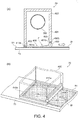
- FIG. 4 schematically illustrates the configuration of the area around the housing of the distributor unit, FIG. 4 (a) being a section view including the mesh belt in the distributor unit, and FIG. 4(b) being an oblique view of the lower part of the distributor unit and the mesh belt.
- the distributor unit 70 includes the drum unit 300 and housing 400.
- the drum unit 300 has a screen 310 with numerous apertures 311 through which airborne material including at least fiber passes, and a cylinder section 315 without apertures 311, disposed to a cylinder 305 that rotates.
- the screen 310 and cylinder section 315 are welded together or fastened together with screws, and rotate in unison.
- the cylinder 305 is made by forming a stainless steel or other type of metal sheet material of uniform thickness into a cylinder, and an opening 306 is provided in both ends.
- Numerous apertures 311 are disposed to the screen 310.
- the screen 310 is configured so that material containing dispersed fibers passes from the apertures 311, and the size and formation area of the apertures 311 are set appropriately according to the size and type of material. Note that the screen 310 is not limited to punched metal, and a metal screen may be used.
- the many apertures 311 are all the same size (area) and are formed at a uniform interval. As a result, material that passes through the apertures 311 accumulates with uniform thickness and density on the mesh belt 73. Interlocked fibers are also untangled as they pass through the apertures 311.
- the cylinder section 315 is a portion having no apertures 311, and is the part that contacts the housing 400.
- the housing 400 has a frame 401 formed from five connected walls with a space inside.
- An opening 406 is disposed instead of a floor at the bottom of the housing 400.
- the housing 400 has a frame interface 401a formed as a round hole in two opposing walls, and a pile seal strip 410 described below is attached to each frame interface 401a.
- the housing 400 surrounds the drum unit 300 so that the screen 310 is on the inside. In other words, the screen 310 portion of the drum unit 300 is in the space inside the housing 400.
- the housing 400 and the cylinder section 315 are also in contact with each other.
- the drum unit 300 has a cylinder section 315a, the screen 310, and a cylinder section 315b disposed along the axis of rotation R; and the housing 400, as shown in FIG. 2 , contacts the surface (cylindrical surface) S1 of the cylinder sections 315a, 315b on the opposite side as the axis of rotation R. Dispersion of material including fibers, for example, that passes through the apertures 311 from the inside of the housing 400 to the outside can be suppressed by this contact between the housing 400 and the cylinder sections 315a, 315b.
- the housing 400 is disposed on the inside of the drum unit 300 on the axis of rotation R of the drum unit 300, a configuration in which the width of the housing 400 is less than the width of the drum unit 300 along the axis of rotation R of the drum unit 300 can be achieved, and the device configuration can be made smaller. Note that because the housing 400 is thus larger than the outside diameter of the drum unit 300 in the direction transverse to the axis of rotation R of the drum unit 300, the housing 400 is positioned inside the drum unit 300.
- the housing 400 in this embodiment of the invention has a pile seal strip 410, and the pile seal strip 410 touches the surface S1 of the cylinder section 315.
- the pile seal strip 410 in this example has a base member and numerous fibers densely implanted on one side of the base.
- the pile seal strip has numerous fibers implanted so densely that fibers that pass through the apertures 311 in the drum unit 300 cannot pass through.
- the other side of the base of the pile seal strip 410 is attached the frame interface 401a of the housing 400, and the distal ends of the fibers of the pile seal strip 410 are configured to contact the surface S1 of the cylinder section 315. There are no apertures in the surface S1 where the pile seal strip 410 contacts the cylinder section 315.
- Surface S1 is preferably smooth at least where the pile seal strip 410 touches. This enables the gap between the frame 401 of the housing 400 and the cylinder section 315 of the drum unit 300 to be substantially closed by the pile seal strip 410. Material including fibers that passes through the apertures 311 in the drum unit 300 therefore stays inside the housing 400, and discharge of material to the outside of the housing 400 can be suppressed. Furthermore, when the drum unit 300 turns on the axis of rotation R, wear where the cylinder section 315 and pile seal strip 410 slide against each other can be suppressed, and the rotational load on the drum unit 300 can be reduced.
- the length of the fibers in the pile seal strip 410 is set longer than the size of the gap between the frame 401 of the housing 400 and the cylinder section 315 of the drum unit 300. This is to ensure the pile seal strip 410 reliably contacts the cylinder section 315.
- the pile seal strip 410 may be disposed to the cylinder section 315.
- the contact area between the pile seal strip 410 and the frame 401 decreases in this event if the drum unit 300 shifts relative to the housing 400 along the axis of rotation R.
- the pile seal strip 410 is preferably disposed to the housing 400 to contact the cylinder section, which is larger than the pile seal strip 410 in the direction along the axis of rotation R.
- this embodiment of the invention also has a stationary flange unit 500 inside the cylinder section 315 of the drum unit 300, and the cylinder section 315 and flange unit 500 are in contact through a second pile seal strip 510.
- a flange unit 500 is inside the cylinder sections 315a, 315b of the drum unit 300.
- the flange unit 500 is fastened to a flange plate 550.
- the flange plate 550 is affixed to an external frame not shown.
- a material supply port 560 for supplying material containing fiber into the drum unit 300 is disposed to the flange plate 550.
- the second pile seal strip 510 is disposed between the inside surface S2 of the cylinder section 315 and the surface 500a of the flange unit 500.
- the second pile seal strip 510 in this example has a base member and numerous fibers densely implanted on one side of the base.
- the pile seal strip has numerous fibers implanted so densely that material containing fiber cannot pass through.
- the other side of the base of the second pile seal strip 510 is attached to the surface 500a of the flange unit 500, and the distal ends of the fibers of the second pile seal strip 510 are configured to contact the inside surface S2 of the cylinder section 315.
- the gap between the flange unit 500 and the cylinder section 315 of the drum unit 300 is substantially closed by the second pile seal strip 510. Discharge of material including fibers of the drum unit 300 from the gap between the cylinder section 315 of the drum unit 300 and the flange unit 500 can therefore be suppressed. Furthermore, because the drum unit 300 turns on the axis of rotation R, wear can be suppressed by use on the sliding part where the cylinder section 315 and the second pile seal strip 510 rub, and the rotational load on the drum unit 300 can be reduced. Note also that the length of the fibers in the second pile seal strip 510 is set longer than the size of the gap between the flange unit 500 and the cylinder section 315 of the drum unit 300.
- the flange unit 500 may also be said to have the second pile seal strip 510.
- the second pile seal strip 510 may be attached to the cylinder section 315.
- the second pile seal strip 510 is also attached to the screen 310 end of the flange unit 500.
- the invention is not so limited, however, and the second pile seal strip 510 may be disposed to a position away from the screen 310. This configuration opens a gap between the flange unit 500 and the cylinder section 315, and the tribological load on the drum unit 300 may increase as a result of material containing fiber getting into this gap.
- the second pile seal strip 510 is therefore preferably attached at the screen 310 end of the flange unit 500 because an increase in the tribological load can be prevented. Note that the drum unit 300 is supported by a support unit not shown, and the weight of the drum unit 300 does not bear on the pile seal strip 410 or the second pile seal strip 510.
- the housing 400 in this embodiment of the invention contacts the web W on the downstream side in the conveyance direction of the web W, and contacts the mesh belt 73 (part of the conveyance unit 100) at a position upstream in the conveyance direction of the web W from the part that contacts the web W on the downstream side.
- the housing 400 has a roller 450 that contacts the web W on the downstream side in the conveyance direction of the web W.
- the housing 400 also has a third pile seal strip 410a that contacts the mesh belt 73 (part of the conveyance unit 100) upstream in the conveyance direction of the web W from the downstream contact position, that is, the location of the roller 450.
- the third pile seal strip 410a in this example has a base member and numerous fibers densely implanted on one side of the base.
- the pile seal strip has numerous fibers implanted so densely that fibers that pass through the drum unit 300 cannot pass through.
- the third pile seal strip 410a is disposed to positions other than where the roller 450 of the housing 400 is located.
- the other side of the base of the third pile seal strip 410a is attached to the frame interface 401a of the housing 400, and the distal ends of the fibers of the third pile seal strip 410a are configured to contact the surface S1 of the mesh belt 73.
- a third pile seal strip 410a is disposed to the three sides of the housing 400 not including the side where the roller 450 is located.
- the gap between three sides of the housing 400 and the mesh belt 73 is substantially closed by the third pile seal strip 410a. So that these three sides of the housing 400 can contact the surface of the mesh belt 73, the width of the mesh belt 73 is greater than the width of the housing 400 in the direction transversely to the direction of travel of the mesh belt 73 (the conveyance direction of the web W). Because the mesh belt 73 moves relative to the distributor unit 70, wear between the mesh belt 73 and the third pile seal strip 410a is suppressed, and the load on the mesh belt 73 can be reduced.
- the length of the fibers in the third pile seal strip 410a is longer than the size of the gap between the frame interface 401a of the frame 401 of the housing 400 and the mesh belt 73. This is so that the third pile seal strip 410a reliably contacts the mesh belt 73.
- a first overhang 402 extends down from the housing 400 on the inside side of the third pile seal strip 410a. The bottom of the first overhang 402 extends to a point not touching the mesh belt 73 and covering at least half of the inside area of the pile seal strip 410a. If fibers from the third pile seal strip 410a separate and get inside the housing 400, the fibers may catch and become interlocked with material containing fiber that passed through the apertures 411, creating large lumps of fiber.
- sheets may be formed with undesirably high density in spots. Separation of fibers from the third pile seal strip 410a can be prevented by covering the inside side of the third pile seal strip 410a with the first overhang 402 of the housing 400. Material containing fiber that passed through the apertures 411 can also be prevented from clinging to the inside of the third pile seal strip 410a.
- the axis of rotation of the roller 450 of the housing 400 extends in a direction transversely (the width of the web W) to the conveyance direction of the web W.
- the length of the roller 450 is equal to the width of the frame 401 across the width of the web W at a position other than the three sides of the frame 401 where the third pile seal strip 410a is disposed.
- a drive unit such as a motor that drives the roller 450 is also disposed to the roller 450.
- the roller 450 can also move, and has an urging member (not shown in the figure) such as a spring member that urges the roller 450.
- the roller 450 can move vertically (the direction perpendicular to the web W accumulation surface), and an urging unit that urges the roller 450 to move vertically is provided.
- the position can change according to the thickness of the web W deposited on the mesh belt by the drum unit 300, and the web W can be conveyed without breaking up even when webs W of different thickness are conveyed.
- the housing 400 has a fourth pile seal strip 410b on the downstream side in the conveyance direction of the web W, and the fourth pile seal strip 410b contacts the roller 450.
- the configuration of the fourth pile seal strip 410b is the same as the configuration of the third pile seal strip 410a, and further description thereof is omitted.
- the other side of the base of the fourth pile seal strip 410b is attached to the frame interface 401b of the housing 400, and the distal ends of the fibers of the fourth pile seal strip 410b are configured to contact the surface of the roller 450.
- the gap between the frame interface 401b of the housing 400 and the roller 450 is substantially closed by the fourth pile seal strip 410b.
- the length of the fibers in the fourth pile seal strip 410b is set longer than the size of the gap between the frame interface 401b of the frame 401 of the housing 400 and the roller 450. This is so that the fourth pile seal strip 410b reliably contacts the roller 450.
- the gap between the housing 400 and the mesh belt 73 is substantially closed by the third pile seal strip 410a on three sides.
- the gap between the housing 400 and the mesh belt 73 is substantially closed by the fourth pile seal strip 410b and the roller 450.
- the operating method of the distributor unit 70 is described next.
- Material including the fibers separated by the cyclone 40 and fusion bonding resin introduced from the additive agent feed unit 60 is supplied through the pipe 204 to the drum unit 300 from the material supply port 560 of the flange plate 550.
- the housing 400 is sized to contact the cylinder section 315 of the drum unit 300, and there is no contact between the housing 400 and the pipe 204 located outside of the cylinder section 315.
- Material is supplied from the pipe 204 through the flange unit 500. The material supplied from the material supply port 560 then flows through the opening 306 in the drum unit 300 to the screen 310 side.
- the drum unit 300 is driven rotationally on the axis of rotation R by a drive unit (such as a motor) not shown.
- a drive unit such as a motor
- the fibers and resin supplied into the drum unit 300 are mixed, and the material including fibers and resin is dispersed by centrifugal force.
- the dispersed material then passes through the apertures 311 in the screen 310.
- Material F that passed through the apertures 311 then drops to the opening 406 in the bottom of the housing 400, and is deposited on the mesh belt 73.
- the pile seal strip 410 is therefore disposed at the joint between the drum unit 300 and housing 400 in this embodiment of the invention. Dispersion of material distributed toward the boundary between the drum unit 300 and housing 400 is therefore limited by the pile seal strip 410.
- a second pile seal strip 510 is disposed to the gap between the drum unit 300 and flange unit 500. Dispersion of material distributed toward the gap between the drum unit 300 and flange unit 500 is therefore limited by the second pile seal strip 510.
- a closed space is thus formed inside the housing 400 by the roller 450 that contacts the web W and the third pile seal strip 410a that contacts the mesh belt 73. While material F that passes through the openings by rotationally driving the drum unit 300 falls toward the opening 406 at the bottom side of the housing 400, the material F including fibers dispersed in air is pulled down by driving the suction device 75 ( FIG. 1 ) disposed on the opposite side of the mesh belt 73. Because material F is deposited on the mesh belt 73 while being suctioned in the closed space of the housing 400, the material F (web W) can be evenly deposited.
- the drum unit 300 is enclosed by a housing 400 so that the screen 310 is inside on the axis of rotation R of the drum unit 300.
- a second pile seal strip 510 is disposed to the gap between the drum unit 300 and flange unit 500.
- This embodiment of the invention is a dry system in which is carried by air. As a result, leakage of air is not a problem. To prevent from getting outside, it is sufficient for the housing 400 and drum unit 300 to be in contact. In a wet system, a rubber or other type of flexible seal member is required. This creates such problems as increasing the rotational load of the drum unit 300, and increasing wear. Compared with using a rubber seal, using a pile seal reduces the rotational load and wear. When materials wear, gaps may form and leak, the worn material may become mixed with the material containing fiber, and the quality of the manufactured sheet drops.
- the present invention is not limited to the foregoing embodiment, and the foregoing embodiment can be modified and improved in many ways. Some examples are described below.
- FIG. 5 schematically illustrates the configuration of the distributor unit in example 1.
- the distributor unit 70a according to example 1 has a drum unit 300 and housing 400.
- the configurations of the drum unit 300, housing 400, and pile seal strip 410 are as described in the embodiment described above, and further description thereof is omitted.
- FIG. 5 there is a stationary flange unit 501 on the outside of the cylinder section 315 of the drum unit 300, and the cylinder section 315 and the flange unit 501 are in contact through the second pile seal strip 510.
- the flange unit 501 is outside the cylinder sections 315a, 315b of the drum unit 300.
- a material supply port 560a for supplying into the drum unit 300 is disposed to the flange unit 501.
- the second pile seal strip 510 is disposed between the surface S1 of the cylinder section 315 and the back side 501a of the flange unit 501.
- the configuration of the second pile seal strip 510 is as described above and further description thereof is omitted.
- the other side of the base of the second pile seal strip 510 is attached to the back side 501a of the flange unit 501, and the distal ends of the fibers of the second pile seal strip 510 are configured to contact the surface S1 of the cylinder section 315.
- the gap between the flange unit 501 and the cylinder section 315 of the drum unit 300 is substantially closed by the second pile seal strip 510. Discharge of in the drum unit 300 from the gap between the cylinder section 315 of the drum unit 300 and the flange unit 501 can therefore be suppressed.
- FIG. 6 schematically illustrates the configuration of the distributor unit in example 2.
- the distributor unit 70b according to example 2 has a drum unit 300a and housing 400.
- the drum unit 300a in this example has a screen 310 with numerous apertures 311, and a cylinder section 315 without apertures 311.
- the drum unit 300a in this example has a neck 320 that reduces the inside diameter of the drum unit 300a formed at each end of the drum unit 300a on the axis of rotation R, and an opening 306a is formed in each neck 320.
- the opening 306a functions as the material supply port through which is supplied into the drum unit 300a.
- the housing 400 has a pile seal strip 410, and the pile seal strip 410 contacts the surface S1 of the cylinder section 315.
- the configuration of the pile seal strip 410 is as described above, and further description thereof is omitted.
- the other side of the base of the pile seal strip 410 is attached to the frame interface 401a of the housing 400, and the distal ends of the fibers of the pile seal strip 410 are configured to touch the surface S1 of the cylinder section 315.
- the gap between the frame 401 of the housing 400 and the cylinder section 315 of the drum unit 300 is substantially closed by the pile seal strip 410.
- that passes through the apertures 311 in the drum unit 300 stays inside the housing 400, and discharge to the outside of the housing 400 can be suppressed. Because the flange unit 500 is omitted, device configuration can be simplified.
- a drive unit for turning the drum unit 300 is not shown in the figures of the foregoing embodiment.
- the drive unit has a gear disposed to the cylinder section 315 outside of the housing 400 (outside of the part that contacts the pile seal strip 410) in FIG. 2 , FIG. 5 , and FIG. 6 , and drives by means of a belt and gears.
- a gear may be used on the neck 320 in FIG. 6 .
- outside surfaces and inside surfaces of the screen 310 and cylinder section 315 are flush in the foregoing embodiment, but there may be a step therebetween.
- a material supply port 560 is provided in both ends of the drum unit 300 in the foregoing embodiment, but may be provided on only one end. In this event, an opening 306a to the cylinder is provided at least on the material supply port 560 side only. Alternatively, one opening may be a material supply port and the other opening used as a discharge port for discharging material that did not pass through the apertures 311.
- the third pile seal strip 410a, fourth pile seal strip 410b, and roller 450 disposed between the housing 400 and the mesh belt 73 in the foregoing embodiment may be omitted.
- the gaps are preferably small enough that material will not leak to the outside of the housing 400.
- the housing 400 in the foregoing embodiment is rectangular, but the frame 401 may be curved or sloped.
- the screen described in the foregoing embodiment may function to separate material that passes the apertures 311 from material that does not pass, may function to detangle material by the material passing through the apertures 311, and may function to disperse material by the material passing through the apertures 311. Or it may have at least one of these functions.
Abstract
Description
- The present invention relates to a sheet manufacturing apparatus.
- A paper recycling system having a dry defibrating unit that shreds and defibrates paper, a first conveyance unit that conveys the defibrated material output by the dry defibrating unit, an air classifier that separates and deinks the defibrated material conveyed by the first conveyance unit, a second conveyance unit that conveys the defibrated material de-inked by the classifier, and a paper-forming unit that produces paper from the defibrated material conveyed by the second conveyance unit is known from the literature. The paper-forming unit is configured with a forming drum having a foraminous screen, and discharges the fibers through the foraminous screen by rotationally driving the forming drum. (See, for example,
PTL 1.) - [PTL 1]
JP-A-2012-144819 - To prevent fiber and other material discharged from the forming drum in the paper-forming unit of the paper recycling system described above from spreading outside of the drum, the forming drum is preferably completely enclosed. However, while the forming drum appears to be covered in the figures in
PTL 1, the cover is not specifically described. As a result, what type of structure can be used to suppress such material from spreading is unknown. Simply surrounding the forming drum also increases the device size. - The present invention is directed to solving at least part of the foregoing problem, and can be achieved by the embodiments or examples described below.
- Example 1: A sheet manufacturing apparatus according to this example is characterized by having: a drum unit including a screen with numerous apertures through which airborne material including at least fiber passes, and a cylinder section without apertures, disposed to a rotating cylinder; a housing unit enclosing the screen part of the drum unit inside and contacting the cylinder section; and a forming unit that forms sheets using material that passed through the apertures.
- Thus comprised, the drum unit is enclosed by the housing unit so that the screen part is inside. The cylinder section of the drum unit and the housing unit are in mutual contact. There are no apertures in the cylinder section. Therefore, material containing fiber that passed through the apertures in the drum unit being discharged from the inside of the housing unit to the outside can be suppressed. In addition, because the housing unit is configured to contact the cylinder section of the drum unit, the length of the housing unit is shorter (the width is shorter) than the length of the drum unit in the direction of the axis of rotation of the drum unit. The size of the device can therefore be reduced.
- Example 2: The drum unit in a sheet manufacturing apparatus according to the foregoing example, characterized by the cylinder section, the screen, and then another cylinder section being disposed in the direction along the axis of rotation; and the housing unit contacting the surface of the cylinder section on the opposite side as the axis of rotation.
- Thus comprised, a cylinder section is disposed on both sides of the screen along the axis of rotation of the drum unit, and the housing unit contacts the outside surface of these cylinder sections. More specifically, device size can be reduced because the housing unit is disposed inside the drum unit in the direction of the axis of rotation of the drum unit. If the drum unit is enclosed by the housing unit outside of the cylinder sections on the axis of rotation, the space inside the housing unit increases. Because material that passes through the apertures spreads easily particularly at the sides of the housing unit when the space inside the housing unit is large, sheets with constant thickness cannot be formed, but because the cylinder section is enclosed by the housing unit in this configuration, the space inside the housing unit is appropriately narrower, material can be deposited to a constant thickness, and sheets with uniform thickness can be manufactured.
- Example 3: The sheet manufacturing apparatus according a foregoing example, characterized by the housing unit having a pile seal, and the pile seal contacting the cylinder section.
- Thus comprised, the cylinder sections and housing unit contact through the pile seal. A pile seal has a bundle of numerous fibers, and can suppress the discharge of fibers and other material that passes through the holes in the drum unit to the outside from inside the housing unit. Because the drum unit is driven rotationally, wear of the drum unit and housing unit can be suppressed and durability can be improved by using a pile seal where the drum unit and housing unit slide against each other.
- Example 4: The sheet manufacturing apparatus according to a foregoing example, characterized by having a stationary flange unit on the inside of the cylinder section; and the cylinder section and the flange unit in contact with each other through a second pile seal.
- Thus comprised, the cylinder section and the flange unit are in contact through a second pile seal. As a result, the discharge of to the outside from inside the drum unit can be suppressed.
-
-
FIG. 1 schematically illustrates the configuration of a sheet manufacturing apparatus according to the invention. -
FIG. 2 schematically illustrates the configuration of the distributor unit. -
FIG. 3 is an oblique view showing the configuration of the drum unit. -
FIG. 4 schematically illustrates the configuration of the area around the housing unit of the distributor unit. -
FIG. 5 schematically illustrates the configuration of a distributor unit according to a first variation of the invention. -
FIG. 6 schematically illustrates the configuration of a distributor unit according to a second variation of the invention. - A preferred embodiment of the invention is described below with reference to the accompanying figures. Note that parts are shown in the accompanying figures in sizes enabling easy recognition thereof, and differ from the actual scale of the actual parts.
- The configuration of the sheet manufacturing apparatus is described first below. The sheet manufacturing apparatus is based on technology for forming a new sheet Pr from feedstock Pu (material to be defibrated) such as virgin pulp paper and recovered paper. The sheet manufacturing apparatus according to this embodiment of the invention has a drum unit including disposed to a rotating cylinder a screen with numerous apertures through which airborne material including at least fiber passes, and a cylinder section without apertures; a housing unit that contacts the cylinder section and surrounds the drum unit so that the screen portion of the drum unit is inside; and a forming unit that forms sheets using material that passes through the apertures. The configuration of the sheet manufacturing apparatus is further described below.
-
FIG. 1 schematically illustrates the configuration of the sheet manufacturing apparatus according to this embodiment of the invention. As shown inFIG. 1 , thesheet manufacturing apparatus 1 according to this embodiment of the invention has asupply unit 10, ashredder 20, adefibrating unit 30, aclassifier 40, areceiver 50, an additiveagent feed unit 60, adistributor unit 70, aconveyance unit 100, acutting unit 110, and a formingunit 200. Thesheet manufacturing apparatus 1 also has a control unit that controls these other pa rts. - The
supply unit 10 supplies recovered paper Pu to theshredder 20. Thesupply unit 10 includes atray 11 for stocking a stack of sheets of recovered paper Pu, and anautomatic sheet feeder 12 for continuously supplying the recovered paper Pu in thetray 11 to theshredder 20. A4 office paper such as typically used in business is an example of the recovered paper Pu that is supplied to thesheet manufacturing apparatus 1. - The
shredder 20 cuts the supplied recovered paper Pu into pieces a few centimeter square. Theshredder 20 hasshredder blades 21, and is configured similarly to a common office shredder but with a wider shredding width. This enables easily cutting the recovered paper Pu that is supplied into pieces of a suitable size. The shredded paper is then conveyed through apipe 201 to the defibratingunit 30. - The defibrating
unit 30 has rotary blades that turn (not shown in the figure), and defibrates and separates the shredded paper supplied from theshredder 20 into fibers. Note that thedefibrating unit 30 in this embodiment of the invention defibrates the shredded paper in air in a dry process. As a result of the defibration process of the defibratingunit 30, ink and toner used for printing, sizing agents, and other coating materials applied to the paper are reduced to particulate several ten microns or less in diameter (referred to below as "ink particles"), and separated from the fibers. The defibrated material output from the defibratingunit 30 is thus the fibers and ink particles obtained by defibration of the shredded paper. The defibratingunit 30 also produces an air current by rotation of the rotary blades, and the defibrated fiber is conveyed by this air current through apipe 202 to theclassifier 40. If a dry defibratingunit 30 without an air blower mechanism is used, a separate blower that produces an air flow from theshredder 20 to the defibratingunit 30 may be added. - The
classifier 40 separates defibrated material into ink particles and fibers. This embodiment of the invention uses a cyclone unit as the classifier 40 (described below as acyclone 40 as the classifier), and separates the conveyed fiber into ink particles and deinked fibers (deinked defibrated material) by an air separation process. Note that an air classifier other than acyclone 40 separator may be used. In this event, an elbow-jet or eddy classifier, for example, may be used as an air classifier instead of acyclone 40. An air classifier produces a helical air flow, and separates and classifies by means of the differences in centrifugal force resulting from the size and density of the defibrated material, and the cut point can be adjusted by adjusting the speed of the air flow and the centrifugal force. As a result, relatively small, relatively low density ink particles can be separated from the fibers that are larger and more dense than the ink particles. Removing the ink particles from the fibers is referred to as "deinking." - The tangential inlet cyclone of the
cyclone 40 has a relatively simple construction. Thecyclone 40 in this embodiment of the invention has aninlet port 40a from thedefibrating unit 30; acylindrical cyclone body 41 to which theinlet port 40a is tangentially attached; aconical section 42 continuing from the bottom of thecyclone body 41; alower discharge port 40b disposed to the bottom of theconical section 42; and anupper discharge port 40c disposed to the top center of thecyclone body 41 for discharging fine particulate. The diameter of theconical section 42 decreases from top to bottom. - In the separation process, the air flow carrying the defibrated material introduced from the
inlet port 40a of thecyclone 40 is converted by thecyclone body 41 andconical section 42 to a circular flow, producing centrifugal force separating the fibers and ink particles. Deinking progresses as the fibers, which are larger and denser than the ink particles, move down to thelower discharge port 42 while the relatively small, low density ink particles are carried to theupper discharge port 40c as dust. A short fiber mixture containing a large amount of ink particles is then discharged from theupper discharge port 40c of thecyclone 40. The discharged short fiber mixture containing a large amount of ink particles is then recovered through apipe 203 connected to theupper discharge port 40c of thecyclone 40 into thereceiver 50. The deinked fiber is conveyed through apipe 204 from thelower discharge port 40b of thecyclone 40 to thedistributor unit 70. Note that a suction unit for efficiently suctioning the short fiber mixture from theupper discharge port 40c may also be disposed to theupper discharge port 40c orpipe 203, for example. - An additive
agent feed unit 60 for adding an additive such as a resin (a fusion bonding resin or thermosetting resin, for example) to the conveyed defibrated fibers is also disposed to thepipe 204 through which the deinked fiber is conveyed from thecyclone 40 to thedistributor unit 70. In addition to fusion bonding resin, additives such as flame retardants, bleaching agents, paper strengtheners, and sizing agents may also be added. These additives are stored in anadditive hopper 61 and introduced through aloading port 62 by a loader mechanism not shown. - The
distributor unit 70 disperses material containing at least fiber into air. Thedistributor unit 70 in this embodiment of the invention has a mechanism for dispersing by means of a rotating motion the material containing fiber and resin that is delivered from thepipe 204. Thedistributor unit 70 in this embodiment of the invention has a drum unit 300 (screen unit) and ahousing 400. - An endless mesh belt 73 (part of the conveyance unit 100) made with mesh and tensioned by tension rollers 72 (four
tension rollers 72 in this embodiment of the invention) is disposed below thedistributor unit 70. Themesh belt 73 moves in one direction by at least one of thetension rollers 72 turning. - A
suction device 75 that produces a downward flow of air through themesh belt 73 is disposed as a suction unit below thedrum unit 300 with themesh belt 73 therebetween. Thesuction device 75 pulls the fibers suspended in air inside thedistributor unit 70 down onto themesh belt 73. - In this configuration, material that passed through the
drum unit 300 is deposited onto themesh belt 73 by the suction power of thesuction device 75. By moving themesh belt 73 in one direction, the fibers and resin can be deposited to form a continuous web W. A single continuous web W can be formed by continuously dispersing material in thedistributor unit 70 and moving themesh belt 73. Note that themesh belt 73 may be made of metal, plastic, or nonwoven cloth, and may be configured in any way enabling fibers to build up on and air to pass through themesh belt 73. Note that if the size of the mesh in themesh belt 73 is too large, fibers may enter the mesh and create irregularities in the formed web W (sheet), and if the mesh is too small, it is difficult for thesuction device 75 to maintain a stable air flow. As a result, the size of the mesh is preferably adjusted appropriately. Thesuction device 75 can be constructed by forming an air-tight box with a window of a desirable size below themesh belt 73, and pulling air in through the window so that the pressure inside the box is lower than the ambient pressure. Note that a web W according to this embodiment of the invention refers to the configuration of an object containing fibers and resin. The web W is therefore still referred to as a web even if the size or other aspect of its form changes by heating, compressing, cutting, conveying or other manipulation of the web W. - The web W formed on the
mesh belt 73 is conveyed by theconveyance unit 100. Theconveyance unit 100 in this embodiment of the invention illustrates the conveyance process of the web W from themesh belt 73 to final deposition as a sheet Pr (web W) in thestacker 160. In addition to themesh belt 73, theconveyor belt mechanism 101 described below and various rollers function as part of theconveyance unit 100. The conveyance unit many be variously configured with at least one conveyor belt or conveyance roller. More specifically, the web W formed on themesh belt 73, which is part of theconveyance unit 100, is first conveyed in the conveyance direction (indicated by the arrow in the figures) by rotation of themesh belt 73. Next, the web W is passed from themesh belt 73 to theconveyor belt mechanism 101, and is conveyed in the conveyance direction (direction of the arrow in the figure). Note that a formingunit 200 that forms a sheet Pr using made of material that passes through thedistributor unit 70 as a web W is included in theconveyance unit 100 in this embodiment of the invention. - A compression unit is disposed on the downstream side of the
distributor unit 70 in the conveyance direction of the web W. The compression unit in this embodiment of the invention is acompression unit 140 comprising a pair ofrollers 141 that apply pressure to the web W. The web W can be compressed by passing the web W between the pair ofrollers 141. As a result, the strength of the web W can be improved. - A
pre-cutter roller 120 is disposed on the downstream side of thecompression unit 140 in the conveyance direction of the web W. Thepre-cutter roller 120 comprises a pair ofrollers rollers - A one-way clutch is used in the drive transfer unit that turns the
pre-cutter roller 120. A one-way clutch has a clutch mechanism that transfers torque in only one direction, and rotates freely in the opposite direction. As a result, because thepre-cutter roller 120 rotates freely when excessive tension is applied to the web W by the speed difference between thepre-cutter roller 120 and thepost-cutter roller 125, tension on the web W is suppressed, and the web W being torn can be prevented. - A
cutting unit 110 that cuts the web W transversely to the conveyance direction of the conveyed web W is disposed on the downstream side of thepre-cutter roller 120 in the conveyance direction of the web W. Thecutting unit 110 has a cutter and cuts the continuous web W into sheets according to a cutting position set to a specific length. Thecutting unit 110 may use a rotary cutter, for example. This enables cutting while conveying the web W. Productivity can therefore be improved because conveyance of the web W is not stopped for cutting. Note that thecutting unit 110 is not limited to a rotary cutter, and other types of cutters may be used. - A
post-cutter roller 125 is disposed on the downstream side of thecutting unit 110 in the conveyance direction of the web W. Thepost-cutter roller 125 comprises a pair ofrollers rollers - Tension can be applied to the web W in this embodiment of the invention by the speed difference between the
pre-cutter roller 120 and thepost-cutter roller 125. In this configuration, thecutting unit 110 is driven to cut the web W while tension is applied to the web W. - A pair of
fuser rollers 151 embodying afuser unit 150 are disposed on the downstream side of thepost-cutter roller 125 in the conveyance direction of the web W. Thefuser unit 150 bonds (fuses) the fibers contained in the web W through the resin. A heater or other type of heating member is disposed in the axial center of thefuser rollers 151, and heat and pressure can be applied to the conveyed web W by passing the web W between the pair offuser rollers 151. By applying heat and pressure to the web W with the pair offuser rollers 151, the resin melts and becomes more easily interlaced with the fibers, the distance between fibers becomes shorter, and the number of points of contact between the fibers increases. As a result, density increases and web W strength is improved. - A
second cutting unit 130 that cuts the web W in the conveyance direction of the web W is disposed on the downstream side of thefuser unit 150 in the conveyance direction of the web W. Thesecond cutting unit 130 has a cutter, and cuts at a specific cutting position in the conveyance direction of the web W. As a result, a sheet Pr (web W) of a desired size is formed. The cut sheet Pr (web W) is then stacked in astacker 160, for example. - A sheet in this embodiment of the invention refers primarily to sheet products that are manufactured from feedstock containing recovered paper, virgin pulp paper, or other type of fiber. The feedstock is not so limited, however, and may be in the form of paperboard or web (or corrugated). The feedstock may also be cellulose or other type of plant fiber, synthetic fiber such as PET (polyethylene terephthalate) and polyester, or wool, silk, or other animal fiber. Sheets as referred to herein are separated into paper and nonwoven cloth. Paper includes thin sheets, recording paper for handwriting and printing, wall paper, packaging paper, color paper, and bristol paper, for example. Nonwoven cloth includes products that are thicker or have lower strength than paper, and includes nonwoven cloth, fiberboard, tissue paper, kitchen paper, cleaning paper, filter paper, liquid absorption materials, sound absorption materials, cushioning materials, and mats, for example.
- Recovered paper as used in this embodiment of the invention mainly refers to paper that has been previously printed on, but any paper product that is used as feedstock is considered recovered paper whether or not the paper was actually used.
- The configuration of the
distributor unit 70 is described in detail next.FIG. 2 schematically illustrates the configuration of thedistributor unit 70,FIG. 2 (a) being a section view through the axis of rotation, andFIG. 2 (b) being a section view through line A-A inFIG. 2 (a) .FIG. 3 is an oblique view showing the configuration of the drum unit.FIG. 4 schematically illustrates the configuration of the area around the housing of the distributor unit,FIG. 4 (a) being a section view including the mesh belt in the distributor unit, andFIG. 4(b) being an oblique view of the lower part of the distributor unit and the mesh belt. As shown inFIG. 2 , thedistributor unit 70 includes thedrum unit 300 andhousing 400. - As shown in
FIG. 3 , thedrum unit 300 has ascreen 310 withnumerous apertures 311 through which airborne material including at least fiber passes, and acylinder section 315 withoutapertures 311, disposed to acylinder 305 that rotates. Thescreen 310 andcylinder section 315 are welded together or fastened together with screws, and rotate in unison. Thecylinder 305 is made by forming a stainless steel or other type of metal sheet material of uniform thickness into a cylinder, and anopening 306 is provided in both ends. - Numerous apertures 311 (punched metal) are disposed to the
screen 310. Thescreen 310 is configured so that material containing dispersed fibers passes from theapertures 311, and the size and formation area of theapertures 311 are set appropriately according to the size and type of material. Note that thescreen 310 is not limited to punched metal, and a metal screen may be used. Themany apertures 311 are all the same size (area) and are formed at a uniform interval. As a result, material that passes through theapertures 311 accumulates with uniform thickness and density on themesh belt 73. Interlocked fibers are also untangled as they pass through theapertures 311. Thecylinder section 315 is a portion having noapertures 311, and is the part that contacts thehousing 400. - As shown in
FIG. 2 (a) and (b) , thehousing 400 has aframe 401 formed from five connected walls with a space inside. Anopening 406 is disposed instead of a floor at the bottom of thehousing 400. Thehousing 400 has aframe interface 401a formed as a round hole in two opposing walls, and apile seal strip 410 described below is attached to eachframe interface 401a. There are no openings in thehousing 400 other than theopening 406 and theframe interfaces 401a. Thehousing 400 surrounds thedrum unit 300 so that thescreen 310 is on the inside. In other words, thescreen 310 portion of thedrum unit 300 is in the space inside thehousing 400. Thehousing 400 and thecylinder section 315 are also in contact with each other. In this embodiment of the invention, as shown inFIG. 3 , thedrum unit 300 has acylinder section 315a, thescreen 310, and acylinder section 315b disposed along the axis of rotation R; and thehousing 400, as shown inFIG. 2 , contacts the surface (cylindrical surface) S1 of thecylinder sections apertures 311 from the inside of thehousing 400 to the outside can be suppressed by this contact between thehousing 400 and thecylinder sections housing 400 is disposed on the inside of thedrum unit 300 on the axis of rotation R of thedrum unit 300, a configuration in which the width of thehousing 400 is less than the width of thedrum unit 300 along the axis of rotation R of thedrum unit 300 can be achieved, and the device configuration can be made smaller. Note that because thehousing 400 is thus larger than the outside diameter of thedrum unit 300 in the direction transverse to the axis of rotation R of thedrum unit 300, thehousing 400 is positioned inside thedrum unit 300. - The
housing 400 in this embodiment of the invention has apile seal strip 410, and thepile seal strip 410 touches the surface S1 of thecylinder section 315. Thepile seal strip 410 in this example has a base member and numerous fibers densely implanted on one side of the base. The pile seal strip has numerous fibers implanted so densely that fibers that pass through theapertures 311 in thedrum unit 300 cannot pass through. The other side of the base of thepile seal strip 410 is attached theframe interface 401a of thehousing 400, and the distal ends of the fibers of thepile seal strip 410 are configured to contact the surface S1 of thecylinder section 315. There are no apertures in the surface S1 where thepile seal strip 410 contacts thecylinder section 315. Surface S1 is preferably smooth at least where thepile seal strip 410 touches. This enables the gap between theframe 401 of thehousing 400 and thecylinder section 315 of thedrum unit 300 to be substantially closed by thepile seal strip 410. Material including fibers that passes through theapertures 311 in thedrum unit 300 therefore stays inside thehousing 400, and discharge of material to the outside of thehousing 400 can be suppressed. Furthermore, when thedrum unit 300 turns on the axis of rotation R, wear where thecylinder section 315 and pileseal strip 410 slide against each other can be suppressed, and the rotational load on thedrum unit 300 can be reduced. Note also that the length of the fibers in thepile seal strip 410 is set longer than the size of the gap between theframe 401 of thehousing 400 and thecylinder section 315 of thedrum unit 300. This is to ensure thepile seal strip 410 reliably contacts thecylinder section 315. Note also that thepile seal strip 410 may be disposed to thecylinder section 315. However, the contact area between thepile seal strip 410 and theframe 401 decreases in this event if thedrum unit 300 shifts relative to thehousing 400 along the axis of rotation R. As a result, thepile seal strip 410 is preferably disposed to thehousing 400 to contact the cylinder section, which is larger than thepile seal strip 410 in the direction along the axis of rotation R. - As shown in
FIG. 2 , this embodiment of the invention also has astationary flange unit 500 inside thecylinder section 315 of thedrum unit 300, and thecylinder section 315 andflange unit 500 are in contact through a secondpile seal strip 510. In this embodiment of the invention, aflange unit 500 is inside thecylinder sections drum unit 300. Theflange unit 500 is fastened to aflange plate 550. Theflange plate 550 is affixed to an external frame not shown. Amaterial supply port 560 for supplying material containing fiber into thedrum unit 300 is disposed to theflange plate 550. - More specifically, the second
pile seal strip 510 is disposed between the inside surface S2 of thecylinder section 315 and thesurface 500a of theflange unit 500. The secondpile seal strip 510 in this example has a base member and numerous fibers densely implanted on one side of the base. The pile seal strip has numerous fibers implanted so densely that material containing fiber cannot pass through. In this embodiment of the invention, the other side of the base of the secondpile seal strip 510 is attached to thesurface 500a of theflange unit 500, and the distal ends of the fibers of the secondpile seal strip 510 are configured to contact the inside surface S2 of thecylinder section 315. As a result, the gap between theflange unit 500 and thecylinder section 315 of thedrum unit 300 is substantially closed by the secondpile seal strip 510. Discharge of material including fibers of thedrum unit 300 from the gap between thecylinder section 315 of thedrum unit 300 and theflange unit 500 can therefore be suppressed. Furthermore, because thedrum unit 300 turns on the axis of rotation R, wear can be suppressed by use on the sliding part where thecylinder section 315 and the secondpile seal strip 510 rub, and the rotational load on thedrum unit 300 can be reduced. Note also that the length of the fibers in the secondpile seal strip 510 is set longer than the size of the gap between theflange unit 500 and thecylinder section 315 of thedrum unit 300. This is to ensure the secondpile seal strip 510 reliably contacts thecylinder section 315. Because the secondpile seal strip 510 is attached to theflange unit 500, theflange unit 500 may also be said to have the secondpile seal strip 510. Note that the secondpile seal strip 510 may be attached to thecylinder section 315. The secondpile seal strip 510 is also attached to thescreen 310 end of theflange unit 500. The invention is not so limited, however, and the secondpile seal strip 510 may be disposed to a position away from thescreen 310. This configuration opens a gap between theflange unit 500 and thecylinder section 315, and the tribological load on thedrum unit 300 may increase as a result of material containing fiber getting into this gap. The secondpile seal strip 510 is therefore preferably attached at thescreen 310 end of theflange unit 500 because an increase in the tribological load can be prevented. Note that thedrum unit 300 is supported by a support unit not shown, and the weight of thedrum unit 300 does not bear on thepile seal strip 410 or the secondpile seal strip 510. - The
housing 400 in this embodiment of the invention contacts the web W on the downstream side in the conveyance direction of the web W, and contacts the mesh belt 73 (part of the conveyance unit 100) at a position upstream in the conveyance direction of the web W from the part that contacts the web W on the downstream side. In this embodiment of the invention, as shown inFIG. 4 (a) , thehousing 400 has aroller 450 that contacts the web W on the downstream side in the conveyance direction of the web W. Thehousing 400 also has a thirdpile seal strip 410a that contacts the mesh belt 73 (part of the conveyance unit 100) upstream in the conveyance direction of the web W from the downstream contact position, that is, the location of theroller 450. - The third
pile seal strip 410a in this example has a base member and numerous fibers densely implanted on one side of the base. The pile seal strip has numerous fibers implanted so densely that fibers that pass through thedrum unit 300 cannot pass through. As shown inFIG. 4 (b) , the thirdpile seal strip 410a is disposed to positions other than where theroller 450 of thehousing 400 is located. In this configuration, the other side of the base of the thirdpile seal strip 410a is attached to theframe interface 401a of thehousing 400, and the distal ends of the fibers of the thirdpile seal strip 410a are configured to contact the surface S1 of themesh belt 73. More specifically, a thirdpile seal strip 410a is disposed to the three sides of thehousing 400 not including the side where theroller 450 is located. As a result, the gap between three sides of thehousing 400 and themesh belt 73 is substantially closed by the thirdpile seal strip 410a. So that these three sides of thehousing 400 can contact the surface of themesh belt 73, the width of themesh belt 73 is greater than the width of thehousing 400 in the direction transversely to the direction of travel of the mesh belt 73 (the conveyance direction of the web W). Because themesh belt 73 moves relative to thedistributor unit 70, wear between themesh belt 73 and the thirdpile seal strip 410a is suppressed, and the load on themesh belt 73 can be reduced. The length of the fibers in the thirdpile seal strip 410a is longer than the size of the gap between theframe interface 401a of theframe 401 of thehousing 400 and themesh belt 73. This is so that the thirdpile seal strip 410a reliably contacts themesh belt 73. Afirst overhang 402 extends down from thehousing 400 on the inside side of the thirdpile seal strip 410a. The bottom of thefirst overhang 402 extends to a point not touching themesh belt 73 and covering at least half of the inside area of thepile seal strip 410a. If fibers from the thirdpile seal strip 410a separate and get inside thehousing 400, the fibers may catch and become interlocked with material containing fiber that passed through the apertures 411, creating large lumps of fiber. If such fiber lumps become mixed into the web W, sheets may be formed with undesirably high density in spots. Separation of fibers from the thirdpile seal strip 410a can be prevented by covering the inside side of the thirdpile seal strip 410a with thefirst overhang 402 of thehousing 400. Material containing fiber that passed through the apertures 411 can also be prevented from clinging to the inside of the thirdpile seal strip 410a. - As shown in
FIG. 4 (b) , the axis of rotation of theroller 450 of thehousing 400 extends in a direction transversely (the width of the web W) to the conveyance direction of the web W. The length of theroller 450 is equal to the width of theframe 401 across the width of the web W at a position other than the three sides of theframe 401 where the thirdpile seal strip 410a is disposed. - A drive unit (not shown in the figure) such as a motor that drives the
roller 450 is also disposed to theroller 450. By thus driving theroller 450, the web W can be more easily pulled in the conveyance direction and the web W can be reliably conveyed. Theroller 450 can also move, and has an urging member (not shown in the figure) such as a spring member that urges theroller 450. In this embodiment of the invention theroller 450 can move vertically (the direction perpendicular to the web W accumulation surface), and an urging unit that urges theroller 450 to move vertically is provided. As a result, the position can change according to the thickness of the web W deposited on the mesh belt by thedrum unit 300, and the web W can be conveyed without breaking up even when webs W of different thickness are conveyed. - The
housing 400 has a fourthpile seal strip 410b on the downstream side in the conveyance direction of the web W, and the fourthpile seal strip 410b contacts theroller 450. The configuration of the fourthpile seal strip 410b is the same as the configuration of the thirdpile seal strip 410a, and further description thereof is omitted. The other side of the base of the fourthpile seal strip 410b is attached to theframe interface 401b of thehousing 400, and the distal ends of the fibers of the fourthpile seal strip 410b are configured to contact the surface of theroller 450. As a result, the gap between theframe interface 401b of thehousing 400 and theroller 450 is substantially closed by the fourthpile seal strip 410b. Because theroller 450 is driven rotationally, wear is suppressed by using the fourthpile seal strip 410b where theroller 450 and fourthpile seal strip 410b rub, and the load on theroller 450 can be reduced. The length of the fibers in the fourthpile seal strip 410b is set longer than the size of the gap between theframe interface 401b of theframe 401 of thehousing 400 and theroller 450. This is so that the fourthpile seal strip 410b reliably contacts theroller 450. - As shown in
FIG. 4 (b) , of the four sides of theframe 401 of thehousing 400 opposite the surface S1 of themesh belt 73, the gap between thehousing 400 and themesh belt 73 is substantially closed by the thirdpile seal strip 410a on three sides. On the remaining one side, the gap between thehousing 400 and themesh belt 73 is substantially closed by the fourthpile seal strip 410b and theroller 450. As a result, material containing fiber that passes through the apertures in thedrum unit 300 stays inside thehousing 400, and discharge of such material outside thehousing 400 can be suppressed. - The operating method of the
distributor unit 70 is described next. Material including the fibers separated by thecyclone 40 and fusion bonding resin introduced from the additiveagent feed unit 60 is supplied through thepipe 204 to thedrum unit 300 from thematerial supply port 560 of theflange plate 550. There is no gap in the connection between thepipe 204 and thematerial supply port 560, and material will not leak from the connection. In this embodiment of the invention, thehousing 400 is sized to contact thecylinder section 315 of thedrum unit 300, and there is no contact between thehousing 400 and thepipe 204 located outside of thecylinder section 315. Material is supplied from thepipe 204 through theflange unit 500. The material supplied from thematerial supply port 560 then flows through theopening 306 in thedrum unit 300 to thescreen 310 side. - The
drum unit 300 is driven rotationally on the axis of rotation R by a drive unit (such as a motor) not shown. As a result, the fibers and resin supplied into thedrum unit 300 are mixed, and the material including fibers and resin is dispersed by centrifugal force. The dispersed material then passes through theapertures 311 in thescreen 310. Material F that passed through theapertures 311 then drops to theopening 406 in the bottom of thehousing 400, and is deposited on themesh belt 73. - When the
drum unit 300 is driven rotationally when material is supplied into thedrum unit 300 and the material is dispersed, some of the dispersed material is distributed to the boundary between thedrum unit 300 andhousing 400, and to the gap between thedrum unit 300 andflange unit 500. As shown inFIG. 2 , thepile seal strip 410 is therefore disposed at the joint between thedrum unit 300 andhousing 400 in this embodiment of the invention. Dispersion of material distributed toward the boundary between thedrum unit 300 andhousing 400 is therefore limited by thepile seal strip 410. In addition, a secondpile seal strip 510 is disposed to the gap between thedrum unit 300 andflange unit 500. Dispersion of material distributed toward the gap between thedrum unit 300 andflange unit 500 is therefore limited by the secondpile seal strip 510. - When material F dispersed by the
drum unit 300 falls to theopening 406 and is deposited on themesh belt 73, some of the dispersed material F is carried to the gap between thehousing 400 and the mesh belt. As shown inFIG. 4 , aroller 450 that contacts the web W, and a fourthpile seal strip 410b disposed between theroller 450 and theframe 401 of thehousing 400, are disposed on the downstream side in the conveyance direction of the web W. A thirdpile seal strip 410a that contacts the surface S1 of themesh belt 73 is also disposed upstream from theroller 450 in the conveyance direction of the web W. As a result, dispersal of material F carried toward the gap between thehousing 400 andmesh belt 73 is limited by the thirdpile seal strip 410a androller 450. - A closed space is thus formed inside the
housing 400 by theroller 450 that contacts the web W and the thirdpile seal strip 410a that contacts themesh belt 73. While material F that passes through the openings by rotationally driving thedrum unit 300 falls toward theopening 406 at the bottom side of thehousing 400, the material F including fibers dispersed in air is pulled down by driving the suction device 75 (FIG. 1 ) disposed on the opposite side of themesh belt 73. Because material F is deposited on themesh belt 73 while being suctioned in the closed space of thehousing 400, the material F (web W) can be evenly deposited. - Effects of the foregoing embodiment are described below.
- The
drum unit 300 is enclosed by ahousing 400 so that thescreen 310 is inside on the axis of rotation R of thedrum unit 300. The cylinder section 315 (315a, 315b) of thedrum unit 300, and thepile seal strip 410 of thehousing 400, touch. As a result, there is no discharge (leakage) of that are dispersed and pass through theapertures 311 in thescreen 310 of thedrum unit 300 to the outside from inside thehousing 400. A secondpile seal strip 510 is disposed to the gap between thedrum unit 300 andflange unit 500. As a result, discharge of dispersed material from thedrum unit 300 to the outside of theflange unit 500 is suppressed. Note that if this embodiment of the invention is used in a wet process using a large amount of water, a tight seal cannot be made with a pile seal strip and water will therefore leak out. This embodiment of the invention is a dry system in which is carried by air. As a result, leakage of air is not a problem. To prevent from getting outside, it is sufficient for thehousing 400 anddrum unit 300 to be in contact. In a wet system, a rubber or other type of flexible seal member is required. This creates such problems as increasing the rotational load of thedrum unit 300, and increasing wear. Compared with using a rubber seal, using a pile seal reduces the rotational load and wear. When materials wear, gaps may form and leak, the worn material may become mixed with the material containing fiber, and the quality of the manufactured sheet drops. - The present invention is not limited to the foregoing embodiment, and the foregoing embodiment can be modified and improved in many ways. Some examples are described below.
- The
distributor unit 70 in the foregoing embodiment is configured with aflange unit 500 inside thecylinder section 315, but the invention is not so limited. For example, configurations having the flange unit disposed outside thecylinder section 315 are also conceivable.FIG. 5 schematically illustrates the configuration of the distributor unit in example 1. As shown inFIG. 5 , thedistributor unit 70a according to example 1 has adrum unit 300 andhousing 400. The configurations of thedrum unit 300,housing 400, and pileseal strip 410 are as described in the embodiment described above, and further description thereof is omitted. - In this example, as shown in
FIG. 5 , there is astationary flange unit 501 on the outside of thecylinder section 315 of thedrum unit 300, and thecylinder section 315 and theflange unit 501 are in contact through the secondpile seal strip 510. In this example, theflange unit 501 is outside thecylinder sections drum unit 300. Amaterial supply port 560a for supplying into thedrum unit 300 is disposed to theflange unit 501. - More specifically, the second
pile seal strip 510 is disposed between the surface S1 of thecylinder section 315 and theback side 501a of theflange unit 501. The configuration of the secondpile seal strip 510 is as described above and further description thereof is omitted. The other side of the base of the secondpile seal strip 510 is attached to theback side 501a of theflange unit 501, and the distal ends of the fibers of the secondpile seal strip 510 are configured to contact the surface S1 of thecylinder section 315. As a result, the gap between theflange unit 501 and thecylinder section 315 of thedrum unit 300 is substantially closed by the secondpile seal strip 510. Discharge of in thedrum unit 300 from the gap between thecylinder section 315 of thedrum unit 300 and theflange unit 501 can therefore be suppressed. - The
distributor unit 70 in the foregoing embodiment is configured with aflange unit 500 inside thecylinder section 315, but the invention is not so limited. For example, configurations in which theflange unit 500 is omitted are also conceivable.FIG. 6 schematically illustrates the configuration of the distributor unit in example 2. As shown inFIG. 6 , thedistributor unit 70b according to example 2 has adrum unit 300a andhousing 400. As described in the foregoing embodiment, thedrum unit 300a in this example has ascreen 310 withnumerous apertures 311, and acylinder section 315 withoutapertures 311. Thedrum unit 300a in this example has aneck 320 that reduces the inside diameter of thedrum unit 300a formed at each end of thedrum unit 300a on the axis of rotation R, and anopening 306a is formed in eachneck 320. Theopening 306a functions as the material supply port through which is supplied into thedrum unit 300a. - The
housing 400 has apile seal strip 410, and thepile seal strip 410 contacts the surface S1 of thecylinder section 315. The configuration of thepile seal strip 410 is as described above, and further description thereof is omitted. The other side of the base of thepile seal strip 410 is attached to theframe interface 401a of thehousing 400, and the distal ends of the fibers of thepile seal strip 410 are configured to touch the surface S1 of thecylinder section 315. As a result, the gap between theframe 401 of thehousing 400 and thecylinder section 315 of thedrum unit 300 is substantially closed by thepile seal strip 410. As a result, that passes through theapertures 311 in thedrum unit 300 stays inside thehousing 400, and discharge to the outside of thehousing 400 can be suppressed. Because theflange unit 500 is omitted, device configuration can be simplified. - A drive unit for turning the
drum unit 300 is not shown in the figures of the foregoing embodiment. The drive unit has a gear disposed to thecylinder section 315 outside of the housing 400 (outside of the part that contacts the pile seal strip 410) inFIG. 2 ,FIG. 5 , andFIG. 6 , and drives by means of a belt and gears. A gear may be used on theneck 320 inFIG. 6 . By placing the drive unit outside thehousing 400, being caught in the drive unit and causing drive problems and increasing the drive load can be suppressed. - The outside surfaces and inside surfaces of the
screen 310 andcylinder section 315 are flush in the foregoing embodiment, but there may be a step therebetween. - A
material supply port 560 is provided in both ends of thedrum unit 300 in the foregoing embodiment, but may be provided on only one end. In this event, anopening 306a to the cylinder is provided at least on thematerial supply port 560 side only. Alternatively, one opening may be a material supply port and the other opening used as a discharge port for discharging material that did not pass through theapertures 311. - Terms such as "same," "uniform," "uniform interval," and "round" in the foregoing embodiment include deviations and cumulative error, and are not limited to meaning exactly the same, uniform, uniform interval, or round.
- The third
pile seal strip 410a, fourthpile seal strip 410b, androller 450 disposed between thehousing 400 and themesh belt 73 in the foregoing embodiment may be omitted. In this event, the gaps are preferably small enough that material will not leak to the outside of thehousing 400. - The
housing 400 in the foregoing embodiment is rectangular, but theframe 401 may be curved or sloped. - The screen described in the foregoing embodiment may function to separate material that passes the
apertures 311 from material that does not pass, may function to detangle material by the material passing through theapertures 311, and may function to disperse material by the material passing through theapertures 311. Or it may have at least one of these functions. -
- 1
- sheet manufacturing apparatus
- 10
- supply unit
- 20
- shredder
- 30
- defibrating unit
- 40
- classifier
- 50
- receiver
- 60
- additive agent feed unit
- 70
- distributor unit
- 73
- mesh belt
- 75
- suction device
- 100
- conveyance unit
- 110
- cutting unit
- 120
- pre-cutter roller
- 125
- post-cutter roller
- 130
- second cutting unit
- 140
- pressing unit
- 150
- fuser unit
- 160
- stacker
- 200
- forming unit
- 300, 300a
- drum unit (screen unit)
- 305
- cylinder
- 306,306a
- opening
- 310
- screen
- 311
- openings
- 315, 315a, 315b
- cylinder section
- 400
- housing
- 401
- frame
- 402
- first overhang
- 403
- second overhang
- 406
- opening
- 410, 410a, 410b
- pile seal strip
- 410a
- third pile seal strip
- 450
- roller
- 500, 501
- flange
- 510
- second pile seal strip
- 560, 560a
- material supply port
- R
- axis of rotation
- W
- web
- Pr
- sheet
Claims (4)
- A sheet manufacturing apparatus comprising:a drum unit including a screen with numerous apertures through which airborne material including at least fiber passes, and a cylinder section without apertures, disposed to a rotating cylinder;a housing unit enclosing the screen part of the drum unit inside and contacting the cylinder section; anda forming unit that forms sheets using material that passed through the apertures.
- The sheet manufacturing apparatus described in claim 1, wherein:the drum unit has the cylinder section, the screen, and the cylinder section disposed in the direction along the axis of rotation; andthe housing unit contacts the surface of the cylinder section on the opposite side as the axis of rotation.
- The sheet manufacturing apparatus described in claim 1 or claim 2, wherein:the housing unit has a pile seal, and the pile seal contacts the cylinder section.
- The sheet manufacturing apparatus described in any of claims 1 to claim 3, further comprising:a stationary flange unit on the inside of the cylinder section;the cylinder section and the flange unit being in contact through a second pile seal.
Applications Claiming Priority (2)
| Application Number | Priority Date | Filing Date | Title |
|---|---|---|---|
| JP2013266609A JP6354154B2 (en) | 2013-12-25 | 2013-12-25 | Sheet manufacturing equipment |
| PCT/JP2014/004434 WO2015097943A1 (en) | 2013-12-25 | 2014-08-28 | Sheet production device |
Publications (3)
| Publication Number | Publication Date |
|---|---|
| EP3088583A1 true EP3088583A1 (en) | 2016-11-02 |
| EP3088583A4 EP3088583A4 (en) | 2017-06-21 |
| EP3088583B1 EP3088583B1 (en) | 2019-08-21 |
Family
ID=53477866
Family Applications (1)
| Application Number | Title | Priority Date | Filing Date |
|---|---|---|---|
| EP14874499.8A Active EP3088583B1 (en) | 2013-12-25 | 2014-08-28 | Sheet production device |
Country Status (6)
| Country | Link |
|---|---|
| US (1) | US10246824B2 (en) |
| EP (1) | EP3088583B1 (en) |
| JP (1) | JP6354154B2 (en) |
| CN (1) | CN105849329B (en) |
| TW (1) | TWI665357B (en) |
| WO (1) | WO2015097943A1 (en) |
Families Citing this family (12)
| Publication number | Priority date | Publication date | Assignee | Title |
|---|---|---|---|---|
| JP6357767B2 (en) * | 2013-12-25 | 2018-07-18 | セイコーエプソン株式会社 | Sheet manufacturing equipment |
| JP6492576B2 (en) | 2014-11-26 | 2019-04-03 | セイコーエプソン株式会社 | Sheet manufacturing equipment |
| JP6500401B2 (en) * | 2014-11-26 | 2019-04-17 | セイコーエプソン株式会社 | Sheet manufacturing equipment |
| US9890500B2 (en) | 2014-11-26 | 2018-02-13 | Seiko Epson Corporation | Sheet manufacturing apparatus |
| EP3321406B1 (en) * | 2015-07-03 | 2020-07-08 | Seiko Epson Corporation | Device for producing sheet, process for producing sheet, resin particles, and sheet |
| JP6544478B2 (en) * | 2016-03-07 | 2019-07-17 | セイコーエプソン株式会社 | Sheet manufacturing equipment |
| EP3508635A4 (en) * | 2016-08-31 | 2020-05-20 | Seiko Epson Corporation | Sheet manufacturing device, and control method of sheet manufacturing device |
| CN106337308A (en) * | 2016-10-31 | 2017-01-18 | 李璇 | Water-saving, high-efficiency and environment-friendly paper machine for office and home use |
| JP7211022B2 (en) * | 2018-11-07 | 2023-01-24 | セイコーエプソン株式会社 | Web manufacturing equipment and sheet manufacturing equipment |
| CN111716484B (en) * | 2019-03-20 | 2022-05-17 | 精工爱普生株式会社 | Fiber splitting processing device and fiber processing device |
| CN110512356B (en) * | 2019-09-06 | 2021-08-24 | 天津工业大学 | Continuous fiber flow laying and forming system |
| JP2022156207A (en) * | 2021-03-31 | 2022-10-14 | セイコーエプソン株式会社 | Method for producing sheet, and apparatus for producing sheet |
Family Cites Families (16)
| Publication number | Priority date | Publication date | Assignee | Title |
|---|---|---|---|---|
| US2218338A (en) * | 1936-09-05 | 1940-10-15 | F W Manning Company Ltd | Method and apparatus for making filter fabric |
| US3010161A (en) * | 1954-02-16 | 1961-11-28 | Wood Conversion Co | Method and means for producing mixed fiber suspensions in air and felts therefrom |
| AU449389B2 (en) * | 1969-07-16 | 1974-05-27 | The Associated Paper Mills Limited | Methods and apparatus for producing fibrous webs andthe production of products therefrom |
| US3680175A (en) * | 1970-07-02 | 1972-08-01 | Union Carbide Corp | Linear apparatus for the production of non-woven fabrics |
| JPS5230630B2 (en) * | 1974-07-08 | 1977-08-09 | ||
| US4157724A (en) * | 1976-08-24 | 1979-06-12 | Persson Torsten B | Method and an apparatus for distributing a disintegrated material onto a layer forming surface |
| US4640810A (en) * | 1984-06-12 | 1987-02-03 | Scan Web Of North America, Inc. | System for producing an air laid web |
| JP2003520912A (en) * | 2000-01-28 | 2003-07-08 | スキャン−ウェブ・アイ/エス | Equipment for dry dispersion of fiber materials |
| US6630096B2 (en) * | 2001-09-04 | 2003-10-07 | Kimberly-Clark Worldwide, Inc. | Multi-stage forming drum commutator |
| DE10249533A1 (en) | 2002-10-23 | 2004-05-06 | Fleissner Gmbh & Co. Maschinenfabrik | Method for operating a device for laying a fleece according to the air laying method and device therefor |
| DK175987B1 (en) * | 2004-08-05 | 2005-10-31 | Dan Core Internat A S | Former head with rotating drum |
| CN201012514Y (en) * | 2006-10-30 | 2008-01-30 | 上海嘉翰轻工机械有限公司 | Gas flow web formation dry way paper machine |
| JP5720255B2 (en) | 2011-01-12 | 2015-05-20 | セイコーエプソン株式会社 | Paper recycling apparatus and paper recycling method |
| EP2664708B1 (en) | 2011-01-12 | 2017-04-12 | Seiko Epson Corporation | Paper recycling system and paper recycling process |
| JP2014008427A (en) * | 2012-06-27 | 2014-01-20 | Suntool Co Ltd | Device for coating hot melt adhesive to base material running top face of coating line |
| CN203295690U (en) | 2013-04-25 | 2013-11-20 | 江阴骏华纺织科技有限公司 | Lapping machine for short collagenous fibers |
-
2013
- 2013-12-25 JP JP2013266609A patent/JP6354154B2/en active Active
-
2014
- 2014-08-28 CN CN201480071113.9A patent/CN105849329B/en active Active
- 2014-08-28 US US15/101,263 patent/US10246824B2/en active Active
- 2014-08-28 EP EP14874499.8A patent/EP3088583B1/en active Active
- 2014-08-28 WO PCT/JP2014/004434 patent/WO2015097943A1/en active Application Filing
- 2014-12-22 TW TW103144859A patent/TWI665357B/en active
Also Published As
| Publication number | Publication date |
|---|---|
| CN105849329B (en) | 2019-04-19 |
| US20160305066A1 (en) | 2016-10-20 |
| EP3088583B1 (en) | 2019-08-21 |
| TW201525236A (en) | 2015-07-01 |
| JP6354154B2 (en) | 2018-07-11 |
| WO2015097943A1 (en) | 2015-07-02 |
| TWI665357B (en) | 2019-07-11 |
| JP2015120998A (en) | 2015-07-02 |
| CN105849329A (en) | 2016-08-10 |
| EP3088583A4 (en) | 2017-06-21 |
| US10246824B2 (en) | 2019-04-02 |
Similar Documents
| Publication | Publication Date | Title |
|---|---|---|
| EP3088583B1 (en) | Sheet production device | |
| EP3088584B1 (en) | Sheet production device | |
| US10563351B2 (en) | Sheet manufacturing apparatus and material defibrating apparatus | |
| US10619302B2 (en) | Sheet manufacturing apparatus | |
| JP6492576B2 (en) | Sheet manufacturing equipment | |
| JP6531871B2 (en) | Sheet manufacturing apparatus and control method of sheet manufacturing apparatus | |
| US9790642B2 (en) | Sheet manufacturing apparatus and sheet manufacturing method | |
| JP6500401B2 (en) | Sheet manufacturing equipment | |
| US11261565B2 (en) | Defibration processing device, and fibrous feedstock recycling device | |
| EP3216904A1 (en) | Sheet manufacturing apparatus and method for manufacturing sheet | |
| JP6569719B2 (en) | Sheet manufacturing equipment | |
| JP6252234B2 (en) | Sheet manufacturing equipment | |
| US9255360B2 (en) | Sheet manufacturing apparatus | |
| JP7183660B2 (en) | Disentanglement processing equipment and sheet manufacturing equipment | |
| JP2016160561A (en) | Sheet production apparatus and sheet production method | |
| JP2016113735A (en) | Apparatus for manufacturing sheet | |
| JP6508362B2 (en) | Sheet manufacturing equipment |
Legal Events
| Date | Code | Title | Description |
|---|---|---|---|
| PUAI | Public reference made under article 153(3) epc to a published international application that has entered the european phase |
Free format text: ORIGINAL CODE: 0009012 |
|
| 17P | Request for examination filed |
Effective date: 20160725 |
|
| AK | Designated contracting states |
Kind code of ref document: A1 Designated state(s): AL AT BE BG CH CY CZ DE DK EE ES FI FR GB GR HR HU IE IS IT LI LT LU LV MC MK MT NL NO PL PT RO RS SE SI SK SM TR |
|
| AX | Request for extension of the european patent |
Extension state: BA ME |
|
| DAX | Request for extension of the european patent (deleted) | ||
| A4 | Supplementary search report drawn up and despatched |
Effective date: 20170524 |
|
| RIC1 | Information provided on ipc code assigned before grant |
Ipc: D04H 1/26 20120101ALI20170518BHEP Ipc: D04H 1/732 20120101AFI20170518BHEP |
|
| STAA | Information on the status of an ep patent application or granted ep patent |
Free format text: STATUS: EXAMINATION IS IN PROGRESS |
|
| 17Q | First examination report despatched |
Effective date: 20180601 |
|
| GRAP | Despatch of communication of intention to grant a patent |
Free format text: ORIGINAL CODE: EPIDOSNIGR1 |
|
| STAA | Information on the status of an ep patent application or granted ep patent |
Free format text: STATUS: GRANT OF PATENT IS INTENDED |
|
| INTG | Intention to grant announced |
Effective date: 20190607 |
|
| GRAS | Grant fee paid |
Free format text: ORIGINAL CODE: EPIDOSNIGR3 |
|
| GRAA | (expected) grant |
Free format text: ORIGINAL CODE: 0009210 |
|
| STAA | Information on the status of an ep patent application or granted ep patent |
Free format text: STATUS: THE PATENT HAS BEEN GRANTED |
|
| AK | Designated contracting states |
Kind code of ref document: B1 Designated state(s): AL AT BE BG CH CY CZ DE DK EE ES FI FR GB GR HR HU IE IS IT LI LT LU LV MC MK MT NL NO PL PT RO RS SE SI SK SM TR |
|
| REG | Reference to a national code |
Ref country code: GB Ref legal event code: FG4D |
|
| REG | Reference to a national code |
Ref country code: CH Ref legal event code: EP |
|
| REG | Reference to a national code |
Ref country code: DE Ref legal event code: R096 Ref document number: 602014052319 Country of ref document: DE |
|
| REG | Reference to a national code |
Ref country code: AT Ref legal event code: REF Ref document number: 1169880 Country of ref document: AT Kind code of ref document: T Effective date: 20190915 |
|
| REG | Reference to a national code |
Ref country code: IE Ref legal event code: FG4D |
|
| REG | Reference to a national code |
Ref country code: LT Ref legal event code: MG4D |
|
| REG | Reference to a national code |
Ref country code: NL Ref legal event code: MP Effective date: 20190821 |
|
| PG25 | Lapsed in a contracting state [announced via postgrant information from national office to epo] |
Ref country code: NL Free format text: LAPSE BECAUSE OF FAILURE TO SUBMIT A TRANSLATION OF THE DESCRIPTION OR TO PAY THE FEE WITHIN THE PRESCRIBED TIME-LIMIT Effective date: 20190821 Ref country code: HR Free format text: LAPSE BECAUSE OF FAILURE TO SUBMIT A TRANSLATION OF THE DESCRIPTION OR TO PAY THE FEE WITHIN THE PRESCRIBED TIME-LIMIT Effective date: 20190821 Ref country code: LT Free format text: LAPSE BECAUSE OF FAILURE TO SUBMIT A TRANSLATION OF THE DESCRIPTION OR TO PAY THE FEE WITHIN THE PRESCRIBED TIME-LIMIT Effective date: 20190821 Ref country code: NO Free format text: LAPSE BECAUSE OF FAILURE TO SUBMIT A TRANSLATION OF THE DESCRIPTION OR TO PAY THE FEE WITHIN THE PRESCRIBED TIME-LIMIT Effective date: 20191121 Ref country code: BG Free format text: LAPSE BECAUSE OF FAILURE TO SUBMIT A TRANSLATION OF THE DESCRIPTION OR TO PAY THE FEE WITHIN THE PRESCRIBED TIME-LIMIT Effective date: 20191121 Ref country code: PT Free format text: LAPSE BECAUSE OF FAILURE TO SUBMIT A TRANSLATION OF THE DESCRIPTION OR TO PAY THE FEE WITHIN THE PRESCRIBED TIME-LIMIT Effective date: 20191223 Ref country code: FI Free format text: LAPSE BECAUSE OF FAILURE TO SUBMIT A TRANSLATION OF THE DESCRIPTION OR TO PAY THE FEE WITHIN THE PRESCRIBED TIME-LIMIT Effective date: 20190821 Ref country code: SE Free format text: LAPSE BECAUSE OF FAILURE TO SUBMIT A TRANSLATION OF THE DESCRIPTION OR TO PAY THE FEE WITHIN THE PRESCRIBED TIME-LIMIT Effective date: 20190821 |
|
| PG25 | Lapsed in a contracting state [announced via postgrant information from national office to epo] |
Ref country code: LV Free format text: LAPSE BECAUSE OF FAILURE TO SUBMIT A TRANSLATION OF THE DESCRIPTION OR TO PAY THE FEE WITHIN THE PRESCRIBED TIME-LIMIT Effective date: 20190821 Ref country code: GR Free format text: LAPSE BECAUSE OF FAILURE TO SUBMIT A TRANSLATION OF THE DESCRIPTION OR TO PAY THE FEE WITHIN THE PRESCRIBED TIME-LIMIT Effective date: 20191122 Ref country code: RS Free format text: LAPSE BECAUSE OF FAILURE TO SUBMIT A TRANSLATION OF THE DESCRIPTION OR TO PAY THE FEE WITHIN THE PRESCRIBED TIME-LIMIT Effective date: 20190821 Ref country code: IS Free format text: LAPSE BECAUSE OF FAILURE TO SUBMIT A TRANSLATION OF THE DESCRIPTION OR TO PAY THE FEE WITHIN THE PRESCRIBED TIME-LIMIT Effective date: 20191221 Ref country code: AL Free format text: LAPSE BECAUSE OF FAILURE TO SUBMIT A TRANSLATION OF THE DESCRIPTION OR TO PAY THE FEE WITHIN THE PRESCRIBED TIME-LIMIT Effective date: 20190821 Ref country code: ES Free format text: LAPSE BECAUSE OF FAILURE TO SUBMIT A TRANSLATION OF THE DESCRIPTION OR TO PAY THE FEE WITHIN THE PRESCRIBED TIME-LIMIT Effective date: 20190821 |
|
| REG | Reference to a national code |
Ref country code: AT Ref legal event code: MK05 Ref document number: 1169880 Country of ref document: AT Kind code of ref document: T Effective date: 20190821 |
|
| PG25 | Lapsed in a contracting state [announced via postgrant information from national office to epo] |
Ref country code: TR Free format text: LAPSE BECAUSE OF FAILURE TO SUBMIT A TRANSLATION OF THE DESCRIPTION OR TO PAY THE FEE WITHIN THE PRESCRIBED TIME-LIMIT Effective date: 20190821 |
|
| PG25 | Lapsed in a contracting state [announced via postgrant information from national office to epo] |
Ref country code: AT Free format text: LAPSE BECAUSE OF FAILURE TO SUBMIT A TRANSLATION OF THE DESCRIPTION OR TO PAY THE FEE WITHIN THE PRESCRIBED TIME-LIMIT Effective date: 20190821 Ref country code: EE Free format text: LAPSE BECAUSE OF FAILURE TO SUBMIT A TRANSLATION OF THE DESCRIPTION OR TO PAY THE FEE WITHIN THE PRESCRIBED TIME-LIMIT Effective date: 20190821 Ref country code: DK Free format text: LAPSE BECAUSE OF FAILURE TO SUBMIT A TRANSLATION OF THE DESCRIPTION OR TO PAY THE FEE WITHIN THE PRESCRIBED TIME-LIMIT Effective date: 20190821 Ref country code: RO Free format text: LAPSE BECAUSE OF FAILURE TO SUBMIT A TRANSLATION OF THE DESCRIPTION OR TO PAY THE FEE WITHIN THE PRESCRIBED TIME-LIMIT Effective date: 20190821 Ref country code: IT Free format text: LAPSE BECAUSE OF FAILURE TO SUBMIT A TRANSLATION OF THE DESCRIPTION OR TO PAY THE FEE WITHIN THE PRESCRIBED TIME-LIMIT Effective date: 20190821 Ref country code: PL Free format text: LAPSE BECAUSE OF FAILURE TO SUBMIT A TRANSLATION OF THE DESCRIPTION OR TO PAY THE FEE WITHIN THE PRESCRIBED TIME-LIMIT Effective date: 20190821 |
|
| PG25 | Lapsed in a contracting state [announced via postgrant information from national office to epo] |
Ref country code: CH Free format text: LAPSE BECAUSE OF NON-PAYMENT OF DUE FEES Effective date: 20190831 Ref country code: LI Free format text: LAPSE BECAUSE OF NON-PAYMENT OF DUE FEES Effective date: 20190831 Ref country code: IS Free format text: LAPSE BECAUSE OF FAILURE TO SUBMIT A TRANSLATION OF THE DESCRIPTION OR TO PAY THE FEE WITHIN THE PRESCRIBED TIME-LIMIT Effective date: 20200224 Ref country code: LU Free format text: LAPSE BECAUSE OF NON-PAYMENT OF DUE FEES Effective date: 20190828 Ref country code: MC Free format text: LAPSE BECAUSE OF FAILURE TO SUBMIT A TRANSLATION OF THE DESCRIPTION OR TO PAY THE FEE WITHIN THE PRESCRIBED TIME-LIMIT Effective date: 20190821 Ref country code: SK Free format text: LAPSE BECAUSE OF FAILURE TO SUBMIT A TRANSLATION OF THE DESCRIPTION OR TO PAY THE FEE WITHIN THE PRESCRIBED TIME-LIMIT Effective date: 20190821 Ref country code: CZ Free format text: LAPSE BECAUSE OF FAILURE TO SUBMIT A TRANSLATION OF THE DESCRIPTION OR TO PAY THE FEE WITHIN THE PRESCRIBED TIME-LIMIT Effective date: 20190821 Ref country code: SM Free format text: LAPSE BECAUSE OF FAILURE TO SUBMIT A TRANSLATION OF THE DESCRIPTION OR TO PAY THE FEE WITHIN THE PRESCRIBED TIME-LIMIT Effective date: 20190821 |
|
| REG | Reference to a national code |
Ref country code: BE Ref legal event code: MM Effective date: 20190831 |
|
| REG | Reference to a national code |
Ref country code: DE Ref legal event code: R097 Ref document number: 602014052319 Country of ref document: DE |
|
| PLBE | No opposition filed within time limit |
Free format text: ORIGINAL CODE: 0009261 |
|
| STAA | Information on the status of an ep patent application or granted ep patent |
Free format text: STATUS: NO OPPOSITION FILED WITHIN TIME LIMIT |
|
| PG2D | Information on lapse in contracting state deleted |
Ref country code: IS |
|
| PG25 | Lapsed in a contracting state [announced via postgrant information from national office to epo] |
Ref country code: IE Free format text: LAPSE BECAUSE OF NON-PAYMENT OF DUE FEES Effective date: 20190828 |
|
| 26N | No opposition filed |
Effective date: 20200603 |
|
| PG25 | Lapsed in a contracting state [announced via postgrant information from national office to epo] |
Ref country code: SI Free format text: LAPSE BECAUSE OF FAILURE TO SUBMIT A TRANSLATION OF THE DESCRIPTION OR TO PAY THE FEE WITHIN THE PRESCRIBED TIME-LIMIT Effective date: 20190821 Ref country code: BE Free format text: LAPSE BECAUSE OF NON-PAYMENT OF DUE FEES Effective date: 20190831 |
|
| PG25 | Lapsed in a contracting state [announced via postgrant information from national office to epo] |
Ref country code: CY Free format text: LAPSE BECAUSE OF FAILURE TO SUBMIT A TRANSLATION OF THE DESCRIPTION OR TO PAY THE FEE WITHIN THE PRESCRIBED TIME-LIMIT Effective date: 20190821 |
|
| PG25 | Lapsed in a contracting state [announced via postgrant information from national office to epo] |
Ref country code: MT Free format text: LAPSE BECAUSE OF FAILURE TO SUBMIT A TRANSLATION OF THE DESCRIPTION OR TO PAY THE FEE WITHIN THE PRESCRIBED TIME-LIMIT Effective date: 20190821 Ref country code: HU Free format text: LAPSE BECAUSE OF FAILURE TO SUBMIT A TRANSLATION OF THE DESCRIPTION OR TO PAY THE FEE WITHIN THE PRESCRIBED TIME-LIMIT; INVALID AB INITIO Effective date: 20140828 |
|
| PG25 | Lapsed in a contracting state [announced via postgrant information from national office to epo] |
Ref country code: MK Free format text: LAPSE BECAUSE OF FAILURE TO SUBMIT A TRANSLATION OF THE DESCRIPTION OR TO PAY THE FEE WITHIN THE PRESCRIBED TIME-LIMIT Effective date: 20190821 |
|
| PGFP | Annual fee paid to national office [announced via postgrant information from national office to epo] |
Ref country code: GB Payment date: 20230706 Year of fee payment: 10 |
|
| PGFP | Annual fee paid to national office [announced via postgrant information from national office to epo] |
Ref country code: FR Payment date: 20230703 Year of fee payment: 10 Ref country code: DE Payment date: 20230703 Year of fee payment: 10 |