EP3088452A1 - Foamed molded article - Google Patents
Foamed molded article Download PDFInfo
- Publication number
- EP3088452A1 EP3088452A1 EP14874087.1A EP14874087A EP3088452A1 EP 3088452 A1 EP3088452 A1 EP 3088452A1 EP 14874087 A EP14874087 A EP 14874087A EP 3088452 A1 EP3088452 A1 EP 3088452A1
- Authority
- EP
- European Patent Office
- Prior art keywords
- resin
- instrument panel
- panel duct
- polyethylene
- molded
- Prior art date
- Legal status (The legal status is an assumption and is not a legal conclusion. Google has not performed a legal analysis and makes no representation as to the accuracy of the status listed.)
- Granted
Links
Images



Classifications
-
- C—CHEMISTRY; METALLURGY
- C08—ORGANIC MACROMOLECULAR COMPOUNDS; THEIR PREPARATION OR CHEMICAL WORKING-UP; COMPOSITIONS BASED THEREON
- C08J—WORKING-UP; GENERAL PROCESSES OF COMPOUNDING; AFTER-TREATMENT NOT COVERED BY SUBCLASSES C08B, C08C, C08F, C08G or C08H
- C08J9/00—Working-up of macromolecular substances to porous or cellular articles or materials; After-treatment thereof
- C08J9/22—After-treatment of expandable particles; Forming foamed products
- C08J9/228—Forming foamed products
-
- B—PERFORMING OPERATIONS; TRANSPORTING
- B29—WORKING OF PLASTICS; WORKING OF SUBSTANCES IN A PLASTIC STATE IN GENERAL
- B29C—SHAPING OR JOINING OF PLASTICS; SHAPING OF MATERIAL IN A PLASTIC STATE, NOT OTHERWISE PROVIDED FOR; AFTER-TREATMENT OF THE SHAPED PRODUCTS, e.g. REPAIRING
- B29C49/00—Blow-moulding, i.e. blowing a preform or parison to a desired shape within a mould; Apparatus therefor
- B29C49/0005—Blow-moulding, i.e. blowing a preform or parison to a desired shape within a mould; Apparatus therefor characterised by the material
-
- C—CHEMISTRY; METALLURGY
- C08—ORGANIC MACROMOLECULAR COMPOUNDS; THEIR PREPARATION OR CHEMICAL WORKING-UP; COMPOSITIONS BASED THEREON
- C08F—MACROMOLECULAR COMPOUNDS OBTAINED BY REACTIONS ONLY INVOLVING CARBON-TO-CARBON UNSATURATED BONDS
- C08F10/00—Homopolymers and copolymers of unsaturated aliphatic hydrocarbons having only one carbon-to-carbon double bond
- C08F10/02—Ethene
-
- C—CHEMISTRY; METALLURGY
- C08—ORGANIC MACROMOLECULAR COMPOUNDS; THEIR PREPARATION OR CHEMICAL WORKING-UP; COMPOSITIONS BASED THEREON
- C08J—WORKING-UP; GENERAL PROCESSES OF COMPOUNDING; AFTER-TREATMENT NOT COVERED BY SUBCLASSES C08B, C08C, C08F, C08G or C08H
- C08J9/00—Working-up of macromolecular substances to porous or cellular articles or materials; After-treatment thereof
- C08J9/0061—Working-up of macromolecular substances to porous or cellular articles or materials; After-treatment thereof characterized by the use of several polymeric components
-
- C—CHEMISTRY; METALLURGY
- C08—ORGANIC MACROMOLECULAR COMPOUNDS; THEIR PREPARATION OR CHEMICAL WORKING-UP; COMPOSITIONS BASED THEREON
- C08J—WORKING-UP; GENERAL PROCESSES OF COMPOUNDING; AFTER-TREATMENT NOT COVERED BY SUBCLASSES C08B, C08C, C08F, C08G or C08H
- C08J9/00—Working-up of macromolecular substances to porous or cellular articles or materials; After-treatment thereof
- C08J9/04—Working-up of macromolecular substances to porous or cellular articles or materials; After-treatment thereof using blowing gases generated by a previously added blowing agent
- C08J9/12—Working-up of macromolecular substances to porous or cellular articles or materials; After-treatment thereof using blowing gases generated by a previously added blowing agent by a physical blowing agent
- C08J9/122—Hydrogen, oxygen, CO2, nitrogen or noble gases
-
- C—CHEMISTRY; METALLURGY
- C08—ORGANIC MACROMOLECULAR COMPOUNDS; THEIR PREPARATION OR CHEMICAL WORKING-UP; COMPOSITIONS BASED THEREON
- C08L—COMPOSITIONS OF MACROMOLECULAR COMPOUNDS
- C08L23/00—Compositions of homopolymers or copolymers of unsaturated aliphatic hydrocarbons having only one carbon-to-carbon double bond; Compositions of derivatives of such polymers
- C08L23/02—Compositions of homopolymers or copolymers of unsaturated aliphatic hydrocarbons having only one carbon-to-carbon double bond; Compositions of derivatives of such polymers not modified by chemical after-treatment
- C08L23/04—Homopolymers or copolymers of ethene
- C08L23/06—Polyethylene
-
- B—PERFORMING OPERATIONS; TRANSPORTING
- B29—WORKING OF PLASTICS; WORKING OF SUBSTANCES IN A PLASTIC STATE IN GENERAL
- B29K—INDEXING SCHEME ASSOCIATED WITH SUBCLASSES B29B, B29C OR B29D, RELATING TO MOULDING MATERIALS OR TO MATERIALS FOR MOULDS, REINFORCEMENTS, FILLERS OR PREFORMED PARTS, e.g. INSERTS
- B29K2023/00—Use of polyalkenes or derivatives thereof as moulding material
- B29K2023/04—Polymers of ethylene
- B29K2023/06—PE, i.e. polyethylene
- B29K2023/0608—PE, i.e. polyethylene characterised by its density
- B29K2023/0633—LDPE, i.e. low density polyethylene
-
- B—PERFORMING OPERATIONS; TRANSPORTING
- B29—WORKING OF PLASTICS; WORKING OF SUBSTANCES IN A PLASTIC STATE IN GENERAL
- B29K—INDEXING SCHEME ASSOCIATED WITH SUBCLASSES B29B, B29C OR B29D, RELATING TO MOULDING MATERIALS OR TO MATERIALS FOR MOULDS, REINFORCEMENTS, FILLERS OR PREFORMED PARTS, e.g. INSERTS
- B29K2023/00—Use of polyalkenes or derivatives thereof as moulding material
- B29K2023/04—Polymers of ethylene
- B29K2023/06—PE, i.e. polyethylene
- B29K2023/0608—PE, i.e. polyethylene characterised by its density
- B29K2023/065—HDPE, i.e. high density polyethylene
-
- B—PERFORMING OPERATIONS; TRANSPORTING
- B29—WORKING OF PLASTICS; WORKING OF SUBSTANCES IN A PLASTIC STATE IN GENERAL
- B29K—INDEXING SCHEME ASSOCIATED WITH SUBCLASSES B29B, B29C OR B29D, RELATING TO MOULDING MATERIALS OR TO MATERIALS FOR MOULDS, REINFORCEMENTS, FILLERS OR PREFORMED PARTS, e.g. INSERTS
- B29K2105/00—Condition, form or state of moulded material or of the material to be shaped
- B29K2105/04—Condition, form or state of moulded material or of the material to be shaped cellular or porous
-
- B—PERFORMING OPERATIONS; TRANSPORTING
- B29—WORKING OF PLASTICS; WORKING OF SUBSTANCES IN A PLASTIC STATE IN GENERAL
- B29L—INDEXING SCHEME ASSOCIATED WITH SUBCLASS B29C, RELATING TO PARTICULAR ARTICLES
- B29L2031/00—Other particular articles
- B29L2031/30—Vehicles, e.g. ships or aircraft, or body parts thereof
-
- C—CHEMISTRY; METALLURGY
- C08—ORGANIC MACROMOLECULAR COMPOUNDS; THEIR PREPARATION OR CHEMICAL WORKING-UP; COMPOSITIONS BASED THEREON
- C08F—MACROMOLECULAR COMPOUNDS OBTAINED BY REACTIONS ONLY INVOLVING CARBON-TO-CARBON UNSATURATED BONDS
- C08F2500/00—Characteristics or properties of obtained polyolefins; Use thereof
- C08F2500/12—Melt flow index or melt flow ratio
-
- C—CHEMISTRY; METALLURGY
- C08—ORGANIC MACROMOLECULAR COMPOUNDS; THEIR PREPARATION OR CHEMICAL WORKING-UP; COMPOSITIONS BASED THEREON
- C08J—WORKING-UP; GENERAL PROCESSES OF COMPOUNDING; AFTER-TREATMENT NOT COVERED BY SUBCLASSES C08B, C08C, C08F, C08G or C08H
- C08J2201/00—Foams characterised by the foaming process
- C08J2201/02—Foams characterised by the foaming process characterised by mechanical pre- or post-treatments
- C08J2201/03—Extrusion of the foamable blend
-
- C—CHEMISTRY; METALLURGY
- C08—ORGANIC MACROMOLECULAR COMPOUNDS; THEIR PREPARATION OR CHEMICAL WORKING-UP; COMPOSITIONS BASED THEREON
- C08J—WORKING-UP; GENERAL PROCESSES OF COMPOUNDING; AFTER-TREATMENT NOT COVERED BY SUBCLASSES C08B, C08C, C08F, C08G or C08H
- C08J2203/00—Foams characterized by the expanding agent
- C08J2203/06—CO2, N2 or noble gases
-
- C—CHEMISTRY; METALLURGY
- C08—ORGANIC MACROMOLECULAR COMPOUNDS; THEIR PREPARATION OR CHEMICAL WORKING-UP; COMPOSITIONS BASED THEREON
- C08J—WORKING-UP; GENERAL PROCESSES OF COMPOUNDING; AFTER-TREATMENT NOT COVERED BY SUBCLASSES C08B, C08C, C08F, C08G or C08H
- C08J2203/00—Foams characterized by the expanding agent
- C08J2203/08—Supercritical fluid
-
- C—CHEMISTRY; METALLURGY
- C08—ORGANIC MACROMOLECULAR COMPOUNDS; THEIR PREPARATION OR CHEMICAL WORKING-UP; COMPOSITIONS BASED THEREON
- C08J—WORKING-UP; GENERAL PROCESSES OF COMPOUNDING; AFTER-TREATMENT NOT COVERED BY SUBCLASSES C08B, C08C, C08F, C08G or C08H
- C08J2205/00—Foams characterised by their properties
- C08J2205/04—Foams characterised by their properties characterised by the foam pores
- C08J2205/052—Closed cells, i.e. more than 50% of the pores are closed
-
- C—CHEMISTRY; METALLURGY
- C08—ORGANIC MACROMOLECULAR COMPOUNDS; THEIR PREPARATION OR CHEMICAL WORKING-UP; COMPOSITIONS BASED THEREON
- C08J—WORKING-UP; GENERAL PROCESSES OF COMPOUNDING; AFTER-TREATMENT NOT COVERED BY SUBCLASSES C08B, C08C, C08F, C08G or C08H
- C08J2207/00—Foams characterised by their intended use
-
- C—CHEMISTRY; METALLURGY
- C08—ORGANIC MACROMOLECULAR COMPOUNDS; THEIR PREPARATION OR CHEMICAL WORKING-UP; COMPOSITIONS BASED THEREON
- C08J—WORKING-UP; GENERAL PROCESSES OF COMPOUNDING; AFTER-TREATMENT NOT COVERED BY SUBCLASSES C08B, C08C, C08F, C08G or C08H
- C08J2323/00—Characterised by the use of homopolymers or copolymers of unsaturated aliphatic hydrocarbons having only one carbon-to-carbon double bond; Derivatives of such polymers
- C08J2323/02—Characterised by the use of homopolymers or copolymers of unsaturated aliphatic hydrocarbons having only one carbon-to-carbon double bond; Derivatives of such polymers not modified by chemical after treatment
- C08J2323/04—Homopolymers or copolymers of ethene
- C08J2323/06—Polyethene
-
- C—CHEMISTRY; METALLURGY
- C08—ORGANIC MACROMOLECULAR COMPOUNDS; THEIR PREPARATION OR CHEMICAL WORKING-UP; COMPOSITIONS BASED THEREON
- C08J—WORKING-UP; GENERAL PROCESSES OF COMPOUNDING; AFTER-TREATMENT NOT COVERED BY SUBCLASSES C08B, C08C, C08F, C08G or C08H
- C08J2423/00—Characterised by the use of homopolymers or copolymers of unsaturated aliphatic hydrocarbons having only one carbon-to-carbon double bond; Derivatives of such polymers
- C08J2423/02—Characterised by the use of homopolymers or copolymers of unsaturated aliphatic hydrocarbons having only one carbon-to-carbon double bond; Derivatives of such polymers not modified by chemical after treatment
- C08J2423/04—Homopolymers or copolymers of ethene
- C08J2423/06—Polyethene
-
- C—CHEMISTRY; METALLURGY
- C08—ORGANIC MACROMOLECULAR COMPOUNDS; THEIR PREPARATION OR CHEMICAL WORKING-UP; COMPOSITIONS BASED THEREON
- C08L—COMPOSITIONS OF MACROMOLECULAR COMPOUNDS
- C08L2205/00—Polymer mixtures characterised by other features
- C08L2205/02—Polymer mixtures characterised by other features containing two or more polymers of the same C08L -group
- C08L2205/025—Polymer mixtures characterised by other features containing two or more polymers of the same C08L -group containing two or more polymers of the same hierarchy C08L, and differing only in parameters such as density, comonomer content, molecular weight, structure
-
- C—CHEMISTRY; METALLURGY
- C08—ORGANIC MACROMOLECULAR COMPOUNDS; THEIR PREPARATION OR CHEMICAL WORKING-UP; COMPOSITIONS BASED THEREON
- C08L—COMPOSITIONS OF MACROMOLECULAR COMPOUNDS
- C08L2207/00—Properties characterising the ingredient of the composition
- C08L2207/06—Properties of polyethylene
- C08L2207/062—HDPE
-
- C—CHEMISTRY; METALLURGY
- C08—ORGANIC MACROMOLECULAR COMPOUNDS; THEIR PREPARATION OR CHEMICAL WORKING-UP; COMPOSITIONS BASED THEREON
- C08L—COMPOSITIONS OF MACROMOLECULAR COMPOUNDS
- C08L2207/00—Properties characterising the ingredient of the composition
- C08L2207/06—Properties of polyethylene
- C08L2207/066—LDPE (radical process)
Definitions
- the present invention relates to a molded foam molded from foamed resin in molten state.
- tubular air-conditioning ducts are used for ventilating air.
- the molded foam includes foamed resin obtained by foaming thermoplastic resin using a foaming agent.
- the molded foam makes it possible to achieve both high thermal insulating property and light weight. Accordingly, there is a growing demand for molded foams.
- blow molding method As a method for manufacturing a molded foam, blow molding method is widely known which includes blowing air into molten foamed resin being clamped by split mold blocks, and expanding the resin.
- Patent Literature 1 JP-A-2005-241157 discloses a foamed duct molded by foamed blow molding which includes adding supercritical fluid as a foaming agent, wherein the foamed duct has an outer surface roughness and expansion ratio within predetermined ranges.
- Patent Literature 2 Japanese Patent No. 4084209 discloses a technology for forming a foamed layer by foaming a foamed layer base material resin using a physical foaming agent.
- the foamed layer base material resin a resin obtained by compounding a specific high-density polyethylene and a specific low-density polyethylene at a specific ratio is used.
- Patent Literature 1 an example is disclosed in which polypropylene-based resin is used as raw material resin for the foamed duct.
- polypropylene-based resin is commonly used, as described in Patent Literature 1.
- the polypropylene-based resin however, has high raw material cost. Accordingly, in recent years, polyethylene-based resin has been used in some cases as the raw material resin for molded foam, as described in Patent Literature 2.
- the polyethylene-based resin raw material is typically less expensive than the polypropylene-based resin raw material. Thus, the polyethylene-based resin raw material enables manufacture of a molded foam at reduced cost.
- the present inventors have attempted to obtain a desired molded foam by using polyethylene-based resin as molded foam raw material resin.
- An object of the present disclosure is to provide a molded foam that can be easily taken out of split mold blocks.
- a molded foam molded by clamping, by split mold blocks, a foamed resin obtained by melting and kneading a polyethylene-based resin.
- the molded foam has a MFR (190°C, g/10 min) of less than 0.8, or the polyethylene-based resin has a MFR (190°C, g/10 min) of not more than 1.0.
- a molded foam that can be easily taken out of the split mold blocks can be obtained.
- FIG. 1 depicts a configuration example of the molded foam 1 according to an aspect of the present disclosure.
- FIG. 9 is a chart for describing the molded foam 1 according to an aspect of the present disclosure.
- the molded foam 1 according to an aspect of the present disclosure is molded by clamping foamed resin with split mold blocks.
- the foamed resin is obtained by melting and kneading polyethylene-based resin.
- the molded foam 1 according to an aspect of the present disclosure is characterized in that, as indicated in FIG. 9 , the molded foam 1 obtained by molding has a melt flow rate (MFR; 190°C, g/10 min) of less than 0.8, or the polyethylene-based resin has a MFR (190°C, g/10 min) of not more than 1.0.
- MFR melt flow rate
- the foamed resin constituting the molded foam 1 can be prevented from becoming attached to the split mold blocks when the molded foam 1 is removed from between the split mold blocks. Accordingly, the molded foam 1 can be easily taken out of the split mold blocks.
- an embodiment of the molded foam 1 according to an aspect of the present disclosure will be described in detail with reference to the attached drawings. In the following description of the embodiment, an instrument panel duct 1 will be described as an example of the molded foam 1.
- FIG. 1 is a schematic plan view of the instrument panel duct 1.
- FIG. 1 there is illustrated the side of the instrument panel duct 1 on which a supply portion 105 for connecting an air conditioner unit (not illustrated) is provided.
- FIG. 2 is a schematic plan view of a part around a fitting portion 102d illustrated in FIG. 1 .
- FIG. 3 is a cross sectional view taken along D-D' of FIG. 2 .
- the instrument panel duct 1 is a lightweight instrument panel duct for allowing cool or warm air supplied from the air conditioner unit to be circulated to desired locations.
- the instrument panel duct 1 according to the present embodiment is molded by blow-molding foamed resin clamped by split mold blocks.
- the foamed resin is obtained by melting and kneading predetermined polyethylene-based resin.
- the instrument panel duct 1 according to the present embodiment has an expansion ratio of 1.3 or more.
- the instrument panel duct 1 has a closed cell structure with a plurality of cells (having a closed cell content of 70% or more).
- the instrument panel duct 1 has an average thickness of 0.5 mm or more.
- the instrument panel duct 1 has a duct inner surface with a surface roughness Rmax of 200 ⁇ m or less. When the surface roughness Rmax is 200 ⁇ m or less, an increase in ventilation efficiency can be achieved.
- the instrument panel duct 1 according to the present embodiment has a tensile fracture elongation at -10°C of 40% or more, and a tensile elastic modulus at normal temperature of 1000 kg/cm 2 or more.
- the tensile fracture elongation at -10°C may be 100% or more.
- the terms used in the present embodiment are defined in the following.
- the expansion ratio is defined as a value obtained by dividing the density of foamed resin used for a molding method of the present embodiment that will be described later, by the apparent density of a tube body X1 (see FIG. 3 ) of the instrument panel duct 1 obtained by the molding method of the present embodiment.
- Tensile fracture elongation A part of the tube body X1 of the instrument panel duct 1 obtained by the molding method of the present embodiment as will be described below is cut out. The cut-out part is stored at -10°C, and, using the part as a No. 2 test specimen in accordance with JIS K-7113, the tension speed is measured at 50 mm/min. The resultant value is defined as the tensile fracture elongation.
- Tensile elastic modulus A part of the tube body X1 of the instrument panel duct 1 obtained by the molding method of the present embodiment as will be described below is cut out. Using the part as a No. 2 test specimen at normal temperature (for example, 23°C) in accordance with JIS K-7113, the tension speed is measured at 50 mm/min. The resultant value is defined as the tensile elastic modulus.
- one end of tube portions 101 (101a to 101d) of the instrument panel duct 1 is provided with a supply portion 105 to be connected to an air conditioner unit (not illustrated).
- the other end of the tube portions 101 (101 a to 101d) is provided with a fitting portions 102 (102a to 102d).
- the tube portions 101 (101 a to 101 d), the supply portion 105, and the fitting portions 102 (102a to 102d) constitute a tube body X1 (see FIG. 3 ) to which flange portions 103 (103a to 103g) are connected.
- an "average thickness” refers to the average of thickness values of the molded article measured at equal intervals of approximately 100 mm along a hollow extension direction of the molded article.
- the thickness is measured of two wall portions of a hollow molded article that are welded via a parting line, each at a position along a direction perpendicular to the parting line, and an average value of the measured thicknesses provides the average thickness.
- the measurement positions are selected so as not to include the flange portions 103 and the like.
- the inside of the tube body X1 is configured with a flow passageway for circulating fluid so as to allow cool or warm air from the air conditioner unit to be circulated therethrough.
- the flow passageway for the fluid supplied from an opening portion 111 of the supply portion 105 into the tube body X1 is divided into four flow passageways A, B-1, B-2, and C, as illustrated in FIG. 1 .
- the fluid supplied via the opening portion 111 of the supply portion 105 into the tube body X1 flows out of the opening portion of the fitting portion 102a via the flow passageway A.
- the fluid also flows out of the opening portion of the fitting portion 102b via the flow passageway B-1.
- the fluid also flows out of the opening portion of the fitting portion 102c via the flow passageway B-2.
- the fluid flows out of the opening portion of the fitting portion 102d via the flow passageway C.
- the configuration of the instrument panel duct 1 around the flow passageway A includes the supply portion 105 provided at one end of the tube portion 101a, with the fitting portion 102a provided at the other end thereof.
- the flange portions 103a and 103e are connected to the tube body X1 configured with the tube portion 101 a, the supply portion 105, and the fitting portion 102a.
- the flange portion 103a is provided with an affixing hole 107a for affixing the instrument panel duct 1 to another tubular member connected by the fitting portion 102a.
- a bolt which is not illustrated
- the flange portion 103e is also provided with an affixing hole 107e.
- the configuration of the instrument panel duct 1 around the flow passageway B-1 includes the supply portion 105 provided at one end of the tube portion 101b, with the fitting portion 102b provided at the other end thereof.
- the flange portion 103b is connected to the tube body X1 configured with the tube portion 101b, the supply portion 105, and the fitting portion 102b.
- the flange portion 103b is provided with an affixing hole 107b for affixing the instrument panel duct 1 to another tubular member connected by the fitting portion 102b.
- a bridge portion 104e for maintaining strength is provided and connected with the tube portions 101a and 101b.
- the configuration of the instrument panel duct 1 around the flow passageway B-2 is similar to the configuration around the flow passageway B-1 described above.
- the configuration of the instrument panel duct 1 around the flow passageway C is similar to the configuration around the flow passageway A described above.
- the flange portion 103g is provided and connected with the tube portions 101b and 101c.
- the flange portion 103g is also provided with an affixing hole 107g.
- the instrument panel duct 1 has the tube body X1 (see FIG. 3 ) with the flange portions 103 (103a to 103g) connected to the outside thereof.
- the tube body X1 refers to the portion including the tube portions 101 (101a to 101d), the supply portion 105, and the fitting portions 102 (102a to 102d).
- the opening portions 100 of the fitting portions 102 have an opening area greater than the opening area of the tube portions 101.
- the opening area of the tube portions 101 refers to the area of an opening portion of the tube portions 101 in a section taken along a direction perpendicular to the direction in which the flow passageway of the instrument panel duct 1 extends.
- the opening area of the opening portions 100 of the fitting portions 102 can be made greater than the opening area of the tube portions 101 by, for example, configuring the fitting portions 102 in bell shape.
- the bell shape refers to a shape with increasingly greater opening area toward the opening end.
- FIG. 4 is a side view of split mold blocks in open state.
- FIG. 5 is a side view of the split mold blocks in closed state.
- FIG. 6 is a cross sectional view of the two split mold blocks in closed state taken along a contact surface thereof as viewed from a split mold block 12a side.
- a cylindrical foamed parison 13 obtained by injecting foamed parison from an annular die 11 is extruded between the split mold blocks 12a and 12b.
- the split mold blocks 12a and 12b are then clamped, whereby, as illustrated in FIG. 5 , the foamed parison 13 is sandwiched between the split mold blocks 12a and 12b. In this way, the foamed parison 13 is stored in cavities 10a and 10b of the split mold blocks 12a and 12b.
- blow-in needle 14 and blow-out needles 15 are simultaneously pierced into the foamed parison 13, thereby piercing predetermined holes provided in the split mold blocks 12a and 12b.
- compressed gas such as compressed air
- the compressed gas passes through the foamed parison 13 and is blown out via the blow-out needles 15. In this way, blow molding is performed at predetermined blow pressure.
- the blow-in needle 14 pierces the position corresponding to the opening portion 111 of the supply portion 105 of the instrument panel duct 1 illustrated in FIG. 1 .
- a blow-in opening for blowing the compressed gas into the foamed parison 13 is formed.
- the blow-out needles 15 pierce the positions corresponding to the opening portions 100 (100a to 100d) of the fitting portions 102 (102a to 102d) of the instrument panel duct 1 illustrated in FIG. 1 .
- blow-out openings for blowing out the compressed gas from inside the foamed parison 13 to the outside are formed.
- the compressed gas can be blown into the foamed parison 13 via the blow-in needle 14.
- the compressed gas passes through the foamed parison 13 and is blown out of the blow-out needles 15. In this way, blow molding can be performed at predetermined blow pressure.
- the compressed gas is blown into the foamed parison 13 from the blow-in needle 14, and discharged out of the cavities 10a and 10b of the split mold blocks 12a and 12b.
- This produces a negative pressure state in the gap between the foamed parison 13 and the cavities 10a and 10b.
- a pressure difference is set (i.e., the pressure inside the foamed parison 13 becomes higher than the external pressure) between the inside and outside of the foamed parison 13 stored in the cavities 10a and 10b in the split mold blocks 12a and 12b. Accordingly, the foamed parison 13 is pressed onto wall surfaces of the cavities 10a and 10b.
- the step of blowing the compressed gas into the foamed parison 13 and the step of producing a negative pressure outside the foamed parison 13 may not be performed simultaneously, and may be performed at different times.
- the foamed parison 13 is clamped by the split mold blocks 12a and 12b with pressing force Z. Accordingly, as described above, the portion of the foamed parison 13 corresponding to the tube body X1 is pressed onto the cavities 10a and 10b at predetermined blow pressure. At the same time, the portions corresponding to the board-like portion Y1 of the flange portions 103 (103a to 103g) and the bridge portions 104 (104e and 104f) are pressed in the thickness direction and compressed to the thickness between the cavities 10a and 10b of the split mold blocks 12a and 12b.
- compressed gas such as compressed air
- compressed air passes through the foamed parison 13 and is blown out of the blow-out needles 15.
- the foamed parison 13 is pressed onto the cavities 10a and 10b by predetermined blow pressure for a predetermined time, and 50% to 80% of the foamed parison 13 from the side of the cavities 10a and 10b in the thickness direction of the tube body X1 is cooled and solidified. Thereafter, the remaining foamed parison 13 in molten state is allowed to naturally solidify while being clamped by the split mold blocks 12a and 12b without performing cooling with compressed gas.
- the temperature of the compressed gas supplied from the blow-in needle 14 into the foamed parison 13 for cooling is set to 10°C to 30°C and preferably room temperature (for example, 23°C).
- room temperature for example, 23°C.
- a temperature adjustment facility may be provided to lower the temperature of the compressed gas supplied from the blow-in needle 14 into the foamed parison 13 below room temperature, whereby the time for cooling the instrument panel duct 1 can be reduced.
- the time (i.e., duration of application) for cooling by compressed gas may preferably be not more than 35 seconds, depending on the compressed gas temperature.
- the resin that may be used for molding the instrument panel duct 1 according to the present embodiment is preferably foamed resin obtained by melting and kneading predetermined polyethylene-based resin so that the MFR of the instrument panel duct 1 as a molded article becomes less than 0.8.
- the MFR of the instrument panel duct 1 as a molded article is 0.8 or more, it may become impossible to obtain the instrument panel duct 1 having high surface roughness, ease of removal, and ease of deburring.
- resin is obtained by heating and melting and thereby defoaming a sample piece cut out of the molded article, and the resin is measured at a test temperature of 190°C and with test load of 2.16 kg according to JIS K-7210. The surface roughness, ease of removal, and ease of deburring will be described with reference to examples that will be described below.
- the polyethylene-based resin forming the foamed resin is formed by melting and kneading a polyethylene-based elemental resin, a high-density polyethylene-based elemental resin, a blend resin obtained by mixing a plurality of low-density polyethylene-based resins, a blend resin obtained by mixing a plurality of high-density polyethylene-based resins, and a blend resin obtained by mixing a low-density polyethylene-based resin and a high-density polyethylene-based resin.
- the MFR (190°C, g/10 min) of the polyethylene-based resin for forming the foamed resin is not more than 1.0.
- the MFRs of the two polyethylene-based resins are set such that the MFR obtained by a calculation process performed on the mixture ratios of the two polyethylene-based resins satisfies the following Expression 1: A ⁇ X / 100 + B ⁇ Y / 100 ⁇ 1.0 where
- the MFR of the low-density polyethylene-based resin is preferably 1.0 to 3.0.
- the foamed resin used for molding the instrument panel duct 1 may also be formed using pulverized material obtained by pulverizing the burr produced during the molding of the instrument panel duct 1. In this case, rather than forming the foamed resin solely with 100% pulverized material, it may be more preferable to form the foamed resin by melting and kneading the pulverized material and virgin material.
- the virgin material refers to unused resin.
- the above-described polyethylene-based resin is used. By using virgin material, degradation of the resin constituting the instrument panel duct 1 can be avoided.
- the ratio of the pulverized material to virgin material that are melted and kneaded may be 90% to 10%.
- Examples of the foaming agent that may be applied when molding the instrument panel duct 1 according to the present embodiment include physical foaming agents, chemical foaming agents, and mixtures thereof.
- Examples of the physical foaming agents include inorganic physical foaming agents such as air, carbonic acid gas, nitrogen gas, and water; organic physical foaming agents such as butane, pentane, hexane, dichloromethane, and dichloroethane; and supercritical fluids thereof.
- the instrument panel duct may be fabricated using carbon dioxide, nitrogen, or the like as supercritical fluid. When nitrogen is used, the instrument panel duct may be fabricated by setting the critical temperature at -149.1°C or above, and the critical pressure at 3.4 MPa or above. When carbon dioxide is used, the instrument panel duct may be fabricated by setting the critical temperature at 31 °C or above and the critical pressure at 7.4 MPa or above.
- the instrument panel duct 1 is taken out of the split mold blocks 12a and 12b. Specifically, the split mold blocks 12a and 12b are opened with the burrs formed on top of the instrument panel duct 1 being gripped by a predetermined machine (such as clips). The instrument panel duct 1 is then removed from between the split mold blocks 12a and 12b.
- a predetermined machine such as clips
- the instrument panel duct 1 according to the present embodiment can be affixed to other tubular members at around the opening portions 100 and 111.
- the strength around the opening portions 100 and 111 can be increased.
- the outer shape of the instrument panel duct 1 according to the present embodiment as a whole may become complex. As a result, it may be difficult to take out the instrument panel duct 1 from the split mold blocks 12a and 12b.
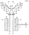
- the instrument panel duct 1 according to the foregoing embodiment may be molded by a molding method which will be described below with reference to FIG. 8 .
- the molding device used by the other molding method includes two extruding machines 50a and 50b as well as the split mold blocks 12a and 12b similar to those used by the preceding exemplary molding method.
- the extruding machines 50 are disposed such that resin sheets P1 and P2 of foamed resin in molten state, including the same material as that of the foamed parison 13 used by the earlier exemplary molding method, can droop substantially in parallel with a predetermined interval between the split mold blocks 12a and 12b.
- adjust rollers 30a and 30b are disposed under T-dies 28a and 28b for extruding the resin sheets P1 and P2.
- the adjust rollers 30a and 30b are used to adjust the thickness of the sheets, for example.
- the thus extruded resin sheets P1 and P2 are sandwiched and clamped between the split mold blocks 12a and 12b, whereby an instrument panel duct is molded.
- the two extruding machines 50 (50a and 50b) have the same configuration. Thus, one of the extruding machines 50 will be described with reference to FIG. 8 .
- the extruding machine 50 includes a cylinder 22 fitted with a hopper 21; a screw (not illustrated) disposed in the cylinder 22; a hydraulic motor 20 coupled with the screw; an accumulator 24 internally in communication with the cylinder 22; a plunger 26 disposed in the accumulator 24; the T-die 28; and a pair of adjust rollers 30.
- Resin pellets are fed from the hopper 21 into the cylinder 22, where the pellets are melted and kneaded by the screw rotated by the hydraulic motor 20. Then, foamed resin in molten state is transported to the accumulator 24. In the accumulator 24, a certain quantity of foamed resin is accumulated. As the plunger 26 is driven, the foamed resin feeds out toward the T-die 28. Via an extrusion slit at the lower end of the T-die 28, a continuous sheet of the foamed resin in molten state is extruded. The resin sheet is sent downward while being compressed between the adjust rollers 30 disposed at an interval. The resin sheet then droops between the split mold blocks 12a and 12b.
- the T-die 28 is fitted with a die bolt 29 for adjusting the slit interval of the extrusion slit.
- a die bolt 29 for adjusting the slit interval of the extrusion slit.
- other slit interval adjusting mechanisms using various known adjustment mechanisms may be employed.
- the resin sheets P1 and P2 having internal foamed cells are extruded from the extrusion slits of the two T-dies 28a and 28b.
- the sheets are adjusted to have a uniform thickness in the vertical direction (i.e., the direction of extrusion).
- the sheets then droop between the split mold blocks 12a and 12b.
- the split mold blocks 12a and 12b are advanced horizontally until molds, not illustrated but positioned on the outer periphery of the split mold blocks 12a and 12b, are closely attached to the resin sheets P1 and P2.
- the resin sheets P1 and P2 are held by the molds on the outer periphery of the split mold blocks 12a and 12b, the resin sheets P1 and P2 are suctioned by vacuum into the cavities 10a and 10b of the split mold blocks 12a and 12b, whereby the resin sheets P1 and P2 each are given shapes conforming to the cavities 10a and 10b.
- the split mold blocks 12a and 12b are then horizontally advanced and clamped and, as in the case of the molding method described earlier, the blow-in needle 14 and the blow-out needles 15 are pierced into the resin sheets P1 and P2.
- compressed gas such as compressed air
- the compressed gas passes through the resin sheets P1 and P2 and is blown out of the blow-out needles 15. In this way, the inside of the portion corresponding to the tube body X1 of the instrument panel duct 1 is cooled.
- split mold blocks 12a and 12b are withdrawn horizontally and removed from the instrument panel duct 1.
- the resin sheets P1 and P2 drooping between the pair of split mold blocks 12a and 12b may have thickness variations due to drawdown or neck-in, for example. Accordingly, in order to prevent this, it may be necessary to adjust the thickness of the resin sheet, extrusion speed, thickness distribution in the extrusion direction, and the like individually.
- the instrument panel duct 1 according to the present embodiment can also be molded in a preferable manner by the other exemplary molding method described with reference to FIG. 8 , in the same way as according to the molding method described with reference to FIG. 4 to FIG. 6 .
- the instrument panel duct 1 adapted to various conditions can be molded by setting mutually different materials, expansion ratios, thicknesses and the like for the two resin sheets P1 and P2.
- instrument panel duct 1 will be described with reference to examples and comparative examples. It should be noted, however, that the present embodiment is not limited to the following examples.
- Foamed resin as raw material resin for the instrument panel duct 1 was prepared by melting and kneading 50 parts by mass of resin A and 50 parts by mass of resin B.
- a foamed blow molding machine equipped with a screw-type extruder having a gas supply opening in a cylinder thereof was used. Via the gas supply opening, supercritical fluid of nitrogen was added.
- a sample of the instrument panel duct 1 having the same shape as the instrument panel duct 1 illustrated in FIG. 1 was molded by the same molding method as described with reference to FIG. 4 to FIG. 6 ; namely, by foamed blow molding, under the following molding conditions.
- the MFR (190°C, g/10 min) of the resin material calculated according to the blend ratio of 50 parts by mass of resin A to 50 parts by mass of resin B was 1.00.
- the MFR (190°C, g/10 min) of the molded instrument panel duct 1 was 0.40.
- the expansion ratio of the molded instrument panel duct 1 was 4.3.
- the surface roughness Rmax of the duct inner surface of the molded instrument panel duct 1 was not more than 200 ⁇ m. Accordingly, the surface roughness was high ("Good").
- MFR The value of MFR was measured at the test temperature of 190°C and with the test load of 2.16 kg according to JIS K-7210.
- the value of expansion ratio was determined by dividing the density of the foamed resin used for molding the instrument panel duct 1 by the apparent density of the tube body X1 of the molded instrument panel duct 1 (see FIG. 3 ).
- the surface roughness Rmax indicates the maximum height measured using a surface roughness meter (SURFCOM 470A manufactured by Tokyo Seimitsu Co., Ltd.). The surface roughness was measured at all regions of the duct inner surface of the instrument panel duct 1. The surface roughness was evaluated by a method such that the surface roughness was considered to be high (“Good”) when Rmax was not higher than 200 ⁇ m in all of the regions. When there was a portion with Rmax of higher than 200 ⁇ m, the surface roughness was considered low (“Poor").
- the ease of removal was evaluated by a method such that the ease of removal was evaluated to be high ("Good") if the foamed resin constituting the instrument panel duct 1 did not become attached to the split mold blocks 12a and 12b when, after blow molding, the instrument panel duct 1 was removed from between the split mold blocks 12a and 12b opened with the burrs formed on top of the instrument panel duct 1 being gripped by a predetermined machine (such as clips), and therefore the instrument panel duct 1 was easily taken out of the split mold blocks 12a and 12b.
- Good the ease of removal was evaluated to be high
- a predetermined machine such as clips
- the ease of removal was evaluated to be low (“Poor”) if, when the instrument panel duct 1 was removed from between the opened split mold blocks 12a and 12b, the foamed resin constituting the instrument panel duct 1 became attached to the split mold blocks 12a and 12b, so that the instrument panel duct 1 was moved by a predetermined distance or more together with the movement of the split mold blocks 12a and 12b.
- the ease of removal was also evaluated to be low (“Poor”) if foamed resin remained on the split mold blocks 12a and 12b.
- the burrs formed on top of the instrument panel duct 1 refer to the portion of foamed resin protruding from the top of the split mold blocks 12a and 12b being clamped.
- the ease of deburring was evaluated by a method such that, when the burrs formed around the instrument panel duct 1 taken out of the split mold blocks 12a and 12b were partially cut with a cutter or the like so as to remove the burrs by hand, for example, the ease of deburring was evaluated to be high (“Good”) if the burrs were easily removed from the instrument panel duct 1. If the burrs became torn and remained on the instrument panel duct 1 during attempted removal, or if the instrument panel duct 1 was deformed during the removal of burrs, the ease of deburring was evaluated to be low (“Poor").
- the burrs may be formed around the parting line of the instrument panel duct 1, with a thin portion formed between the instrument panel duct 1 and the burrs by pinch-off. The burrs are cut off at the thin portion.
- the instrument panel duct 1 was molded by the same method as according to example 1 with the exception that the foamed resin as raw material resin of the instrument panel duct 1 was prepared by melting and kneading 60 parts by mass of resin A and 40 parts by mass of resin B.
- the MFR (190°C, g/10 min) of the resin material calculated according to the blend ratio of 60 parts by mass of resin A to 40 parts by mass of resin B was 0.86.
- the MFR (190°C, g/10 min) of the molded instrument panel duct 1 was 0.37.
- the expansion ratio of the molded instrument panel duct 1 was 3.9.
- the instrument panel duct 1 was molded by the same method as according to example 1 with the exception that the foamed resin as raw material resin of the instrument panel duct 1 was prepared by melting and kneading 70 parts by mass of resin A and 30 parts by mass of resin B.
- the MFR (190°C, g/10 min) of the resin material calculated according to the blend ratio of 70 parts by mass of resin A to 30 parts by mass of resin B was 0.72.
- the MFR (190°C, g/10 min) of the molded instrument panel duct 1 was 0.26.
- the expansion ratio of the molded instrument panel duct 1 was 2.8.
- the instrument panel duct 1 was molded by the same method as according to example 1 with the exception that the foamed resin as raw material resin of the instrument panel duct 1 was prepared by melting and kneading 80 parts by mass of resin A and 20 parts by mass of resin B.
- the MFR (190°C, g/10 min) of the resin material calculated according to the blend ratio of 80 parts by mass of resin A to 20 parts by mass of resin B was 0.58.
- the MFR (190°C, g/10 min) of the molded instrument panel duct 1 was 0.22.
- the expansion ratio of the molded instrument panel duct 1 was 2.2.
- the instrument panel duct 1 was molded by the same method as according to example 1 with the exception that the foamed resin as raw material resin of the instrument panel duct 1 was prepared by melting and kneading 90 parts by mass of resin A and 10 parts by mass of resin B.
- the MFR (190°C, g/10 min) of the resin material calculated according to the blend ratio of 90 parts by mass of resin A to 10 parts by mass of resin B was 0.44.
- the MFR (190°C, g/10 min) of the molded instrument panel duct 1 was 0.18.
- the expansion ratio of the molded instrument panel duct 1 was 1.6.
- the instrument panel duct 1 was molded by the same method as according to example 1 with the exception that the foamed resin as raw material resin of the instrument panel duct 1 was prepared by melting and kneading 60 parts by mass of resin A and 40 parts by mass of resin C.
- the MFR (190°C, g/10 min) of the foamed resin obtained by melting and kneading resin A and resin C was 0.9.
- the MFR (190°C, g/10 min) of the resin material calculated according to the blend ratio of 60 parts by mass of resin A to 40 parts by mass of resin C was 0.90.
- the MFR (190°C, g/10 min) of the molded instrument panel duct 1 was 0.39.
- the expansion ratio of the molded instrument panel duct 1 was 1.6.
- the instrument panel duct 1 was molded by the same method as according to example 1 with the exception that the foamed resin as raw material resin of the instrument panel duct 1 was prepared by melting and kneading 60 parts by mass of resin A and 40 parts by mass of resin D.
- the MFR (190°C, g/10 min) of the foamed resin obtained by melting and kneading resin A and resin D was 0.34.
- the MFR (190°C, g/10 min) of the resin material calculated according to the blend ratio of 60 parts by mass of resin A to 40 parts by mass of resin D was 0.34.
- the MFR (190°C, g/10 min) of the molded instrument panel duct 1 was 0.17.
- the expansion ratio of the molded instrument panel duct 1 was 1.3.
- the instrument panel duct 1 was molded by the same method as according to example 1 with the exception that the foamed resin as raw material resin of the instrument panel duct 1 was prepared by melting and kneading 100 parts by mass of resin D.
- the MFR (190°C, g/10 min) of the resin material calculated according to the blend ratio of 100 parts by mass of resin D was 0.40.
- the MFR (190°C, g/10 min) of the molded instrument panel duct 1 was 0.18.
- the expansion ratio of the molded instrument panel duct 1 was 1.6.
- the instrument panel duct 1 was molded by the same method as according to example 1 with the exception that the foamed resin as raw material resin of the instrument panel duct 1 was prepared by melting and kneading 100 parts by mass of resin B.
- the MFR (190°C, g/10 min) of the resin material calculated according to the blend ratio of 100 parts by mass of resin B was 1.70.
- the MFR (190°C, g/10 min) of the molded instrument panel duct 1 was 0.80.
- the expansion ratio of the molded instrument panel duct 1 was 5.0.
- the surface roughness Rmax of the duct inner surface of the molded instrument panel duct 1 was not more than 200 ⁇ m. Accordingly, the surface roughness was high ("Good").
- the instrument panel duct 1 was molded by the same method as according to example 1 with the exception that the foamed resin as raw material resin of the instrument panel duct 1 was prepared by melting and kneading 60 parts by mass of resin E and 40 parts by mass of resin B.
- the MFR (190°C, g/10 min) of the resin material calculated according to the blend ratio of 60 parts by mass of resin E to 40 parts by mass of resin B was 3.68.
- the MFR (190°C, g/10 min) of the molded instrument panel duct 1 was 3.20.
- the expansion ratio of the molded instrument panel duct 1 was 4.3.
- the surface roughness Rmax of the duct inner surface of the molded instrument panel duct I was partly higher than 200 ⁇ m. Accordingly, the surface roughness was low ("Poor").
- FIG. 9 shows the test results for examples 1 to 8 and comparative examples 1 and 2. Specifically, FIG. 9 shows the blend ratios of the resin material used when molding the instrument panel duct 1 according to examples 1 to 8 and comparative examples 1 and 2; the MFRs of the resin material calculated according to the blend ratios; the MFRs of the molded instrument panel duct 1; and the expansion ratios, surface roughness, ease of removal, and ease of deburring of the molded instrument panel duct 1.
- the instrument panel duct 1 having high surface roughness, ease of removal, and ease of deburring was obtained when the MFR of the molded instrument panel duct 1 was set to be less than 0.8, or when the MFR of the resin material calculated according to the blend ratio was set to be not more than 1.0.
- instrument panel duct 1 having high expansion ratios can be obtained by using foamed resin obtained by mixing high-density polyethylene-based resin and low-density polyethylene-based resin.
- instrument panel duct 1 having high expansion ratios can be obtained by using foamed resin obtained by mixing polyethylene-based resin manufactured by autoclave process.
- the instrument panel duct 1 having high surface roughness, ease of removal, and ease of deburring can be obtained by using low-density polyethylene-based resin with the MFR of 1.0 to 3.0, and by setting the MFR of the molded instrument panel duct 1 to be less than 0.8 or by setting the MFR of the resin material calculated according to the blend ratio to be not more than 1.0.
- the present invention may also be applied to, e.g., a rear air-conditioner duct and the like.
Landscapes
- Chemical & Material Sciences (AREA)
- Engineering & Computer Science (AREA)
- Polymers & Plastics (AREA)
- Health & Medical Sciences (AREA)
- Chemical Kinetics & Catalysis (AREA)
- Medicinal Chemistry (AREA)
- Organic Chemistry (AREA)
- Materials Engineering (AREA)
- Manufacturing & Machinery (AREA)
- Mechanical Engineering (AREA)
- Blow-Moulding Or Thermoforming Of Plastics Or The Like (AREA)
- Manufacture Of Porous Articles, And Recovery And Treatment Of Waste Products (AREA)
- Molding Of Porous Articles (AREA)
- Casting Or Compression Moulding Of Plastics Or The Like (AREA)
Abstract
Description
- The present invention relates to a molded foam molded from foamed resin in molten state.
- In air conditioning devices for automobiles, for example, tubular air-conditioning ducts are used for ventilating air.
- An air-conditioning duct using a molded foam is known. The molded foam includes foamed resin obtained by foaming thermoplastic resin using a foaming agent. The molded foam makes it possible to achieve both high thermal insulating property and light weight. Accordingly, there is a growing demand for molded foams.
- As a method for manufacturing a molded foam, blow molding method is widely known which includes blowing air into molten foamed resin being clamped by split mold blocks, and expanding the resin.
- In an example of technical literature of an application filed prior to the present invention, Patent Literature 1 (
JP-A-2005-241157 - Patent Literature 2 (Japanese Patent No.
4084209 -
- Patent Literature 1:
JP-A-2005-241157 - Patent Literature 2: Japanese Patent No.
4084209 - In
Patent Literature 1, an example is disclosed in which polypropylene-based resin is used as raw material resin for the foamed duct. As the raw material resin for a molded foam, polypropylene-based resin is commonly used, as described inPatent Literature 1. The polypropylene-based resin, however, has high raw material cost. Accordingly, in recent years, polyethylene-based resin has been used in some cases as the raw material resin for molded foam, as described inPatent Literature 2. The polyethylene-based resin raw material is typically less expensive than the polypropylene-based resin raw material. Thus, the polyethylene-based resin raw material enables manufacture of a molded foam at reduced cost. - The present inventors have attempted to obtain a desired molded foam by using polyethylene-based resin as molded foam raw material resin.
- It turned out, however, that, depending on the polyethylene-based resin used as the molded foam raw material resin, the resin constituting the molded foam sometimes becomes attached to split mold blocks when the molded foam that has been molded while being clamped by the split mold blocks is taken out of the split mold blocks. As a result, the molded foam cannot be easily removed from the split mold blocks. Accordingly, there is a need for taking out the molded foam from the split mold blocks easily.
- An object of the present disclosure is to provide a molded foam that can be easily taken out of split mold blocks.
- According to an aspect of the present disclosure, there is provided a molded foam molded by clamping, by split mold blocks, a foamed resin obtained by melting and kneading a polyethylene-based resin. The molded foam has a MFR (190°C, g/10 min) of less than 0.8, or the polyethylene-based resin has a MFR (190°C, g/10 min) of not more than 1.0.
- According to the present invention, a molded foam that can be easily taken out of the split mold blocks can be obtained.
-
-
FIG. 1 is a plan view of aninstrument panel duct 1 according to an embodiment. -
FIG. 2 depicts a part of theinstrument panel duct 1 around afitting portion 102d thereof. -
FIG. 3 is a cross sectional view taken along D-D' ofFIG. 2 . -
FIG. 4 is a first diagram illustrating an exemplary molding method for theinstrument panel duct 1 according to the present embodiment. -
FIG. 5 is a second diagram illustrating the exemplary molding method for theinstrument panel duct 1 according to the present embodiment. -
FIG. 6 is a third diagram illustrating the exemplary molding method for theinstrument panel duct 1 according to the present embodiment. -
FIG. 7 depicts parts around thefitting portion 102d being clamped by split mold blocks. -
FIG. 8 is a diagram illustrating another exemplary molding method. -
FIG. 9 is a chart of examples and comparative examples. - With reference to
FIG. 1 andFIG. 9 , the outline of an embodiment of a moldedfoam 1 according to an aspect of the present disclosure will be described.FIG. 1 depicts a configuration example of the moldedfoam 1 according to an aspect of the present disclosure.FIG. 9 is a chart for describing themolded foam 1 according to an aspect of the present disclosure. - The molded
foam 1 according to an aspect of the present disclosure is molded by clamping foamed resin with split mold blocks. The foamed resin is obtained by melting and kneading polyethylene-based resin. The moldedfoam 1 according to an aspect of the present disclosure is characterized in that, as indicated inFIG. 9 , themolded foam 1 obtained by molding has a melt flow rate (MFR; 190°C, g/10 min) of less than 0.8, or the polyethylene-based resin has a MFR (190°C, g/10 min) of not more than 1.0. - When the MFR of the
molded foam 1 obtained by molding is set to be less than 0.8, or when the MFR of the polyethylene-based resin is set to be not more than 1.0, the foamed resin constituting themolded foam 1 can be prevented from becoming attached to the split mold blocks when the moldedfoam 1 is removed from between the split mold blocks. Accordingly, the moldedfoam 1 can be easily taken out of the split mold blocks. In the following, an embodiment of themolded foam 1 according to an aspect of the present disclosure will be described in detail with reference to the attached drawings. In the following description of the embodiment, aninstrument panel duct 1 will be described as an example of the moldedfoam 1. - With reference to
FIG. 1 to FIG. 3 , a configuration example of theinstrument panel duct 1 according to the present embodiment will be described.FIG. 1 is a schematic plan view of theinstrument panel duct 1. InFIG. 1 , there is illustrated the side of theinstrument panel duct 1 on which asupply portion 105 for connecting an air conditioner unit (not illustrated) is provided.FIG. 2 is a schematic plan view of a part around afitting portion 102d illustrated inFIG. 1 .FIG. 3 is a cross sectional view taken along D-D' ofFIG. 2 . - The
instrument panel duct 1 according to the present embodiment is a lightweight instrument panel duct for allowing cool or warm air supplied from the air conditioner unit to be circulated to desired locations. - The
instrument panel duct 1 according to the present embodiment is molded by blow-molding foamed resin clamped by split mold blocks. The foamed resin is obtained by melting and kneading predetermined polyethylene-based resin. - The
instrument panel duct 1 according to the present embodiment has an expansion ratio of 1.3 or more. Theinstrument panel duct 1 has a closed cell structure with a plurality of cells (having a closed cell content of 70% or more). Theinstrument panel duct 1 has an average thickness of 0.5 mm or more. Theinstrument panel duct 1 has a duct inner surface with a surface roughness Rmax of 200 µm or less. When the surface roughness Rmax is 200 µm or less, an increase in ventilation efficiency can be achieved. Preferably, theinstrument panel duct 1 according to the present embodiment has a tensile fracture elongation at -10°C of 40% or more, and a tensile elastic modulus at normal temperature of 1000 kg/cm2 or more. Preferably, the tensile fracture elongation at -10°C may be 100% or more. The terms used in the present embodiment are defined in the following. - Expansion ratio: The expansion ratio is defined as a value obtained by dividing the density of foamed resin used for a molding method of the present embodiment that will be described later, by the apparent density of a tube body X1 (see
FIG. 3 ) of theinstrument panel duct 1 obtained by the molding method of the present embodiment. - Tensile fracture elongation: A part of the tube body X1 of the
instrument panel duct 1 obtained by the molding method of the present embodiment as will be described below is cut out. The cut-out part is stored at -10°C, and, using the part as a No. 2 test specimen in accordance with JIS K-7113, the tension speed is measured at 50 mm/min. The resultant value is defined as the tensile fracture elongation. - Tensile elastic modulus: A part of the tube body X1 of the
instrument panel duct 1 obtained by the molding method of the present embodiment as will be described below is cut out. Using the part as a No. 2 test specimen at normal temperature (for example, 23°C) in accordance with JIS K-7113, the tension speed is measured at 50 mm/min. The resultant value is defined as the tensile elastic modulus. - As illustrated in
FIG. 1 , one end of tube portions 101 (101a to 101d) of theinstrument panel duct 1 according to the present embodiment is provided with asupply portion 105 to be connected to an air conditioner unit (not illustrated). The other end of the tube portions 101 (101 a to 101d) is provided with a fitting portions 102 (102a to 102d). The tube portions 101 (101 a to 101 d), thesupply portion 105, and the fitting portions 102 (102a to 102d) constitute a tube body X1 (seeFIG. 3 ) to which flange portions 103 (103a to 103g) are connected. - In the present embodiment, an "average thickness" refers to the average of thickness values of the molded article measured at equal intervals of approximately 100 mm along a hollow extension direction of the molded article. For example, the thickness is measured of two wall portions of a hollow molded article that are welded via a parting line, each at a position along a direction perpendicular to the parting line, and an average value of the measured thicknesses provides the average thickness. The measurement positions are selected so as not to include the flange portions 103 and the like.
- The inside of the tube body X1 is configured with a flow passageway for circulating fluid so as to allow cool or warm air from the air conditioner unit to be circulated therethrough.
- The flow passageway for the fluid supplied from an
opening portion 111 of thesupply portion 105 into the tube body X1 is divided into four flow passageways A, B-1, B-2, and C, as illustrated inFIG. 1 . The fluid supplied via theopening portion 111 of thesupply portion 105 into the tube body X1 flows out of the opening portion of thefitting portion 102a via the flow passageway A. The fluid also flows out of the opening portion of thefitting portion 102b via the flow passageway B-1. The fluid also flows out of the opening portion of thefitting portion 102c via the flow passageway B-2. In addition, the fluid flows out of the opening portion of thefitting portion 102d via the flow passageway C. - The configuration of the
instrument panel duct 1 around the flow passageway A includes thesupply portion 105 provided at one end of thetube portion 101a, with thefitting portion 102a provided at the other end thereof. To the tube body X1 configured with thetube portion 101 a, thesupply portion 105, and thefitting portion 102a, theflange portions flange portion 103a is provided with anaffixing hole 107a for affixing theinstrument panel duct 1 to another tubular member connected by thefitting portion 102a. By inserting a bolt, which is not illustrated, through the affixinghole 107a and fastening the bolt with a nut, theinstrument panel duct 1 can be affixed with respect to the other tubular member. Theflange portion 103e is also provided with anaffixing hole 107e. - The configuration of the
instrument panel duct 1 around the flow passageway B-1 includes thesupply portion 105 provided at one end of thetube portion 101b, with thefitting portion 102b provided at the other end thereof. To the tube body X1 configured with thetube portion 101b, thesupply portion 105, and thefitting portion 102b, theflange portion 103b is connected. Theflange portion 103b is provided with an affixinghole 107b for affixing theinstrument panel duct 1 to another tubular member connected by thefitting portion 102b. - At a narrow interval portion between the
tube portions bridge portion 104e for maintaining strength is provided and connected with thetube portions - The configuration of the
instrument panel duct 1 around the flow passageway B-2 is similar to the configuration around the flow passageway B-1 described above. - The configuration of the
instrument panel duct 1 around the flow passageway C is similar to the configuration around the flow passageway A described above. - Between the
tube portions flange portion 103g is provided and connected with thetube portions flange portion 103g is also provided with an affixinghole 107g. - As illustrated in
FIG. 1 , theinstrument panel duct 1 according to the present embodiment has the tube body X1 (seeFIG. 3 ) with the flange portions 103 (103a to 103g) connected to the outside thereof. The tube body X1 refers to the portion including the tube portions 101 (101a to 101d), thesupply portion 105, and the fitting portions 102 (102a to 102d). - In the
instrument panel duct 1 according to the present embodiment, the openingportions 100 of the fitting portions 102 have an opening area greater than the opening area of the tube portions 101. The opening area of the tube portions 101refers to the area of an opening portion of the tube portions 101 in a section taken along a direction perpendicular to the direction in which the flow passageway of theinstrument panel duct 1 extends. The opening area of the openingportions 100 of the fitting portions 102 can be made greater than the opening area of the tube portions 101 by, for example, configuring the fitting portions 102 in bell shape. The bell shape refers to a shape with increasingly greater opening area toward the opening end. - With reference to
FIG. 4 to FIG. 6 , an exemplary molding method for theinstrument panel duct 1 according to the present embodiment will be described.FIG. 4 is a side view of split mold blocks in open state.FIG. 5 is a side view of the split mold blocks in closed state.FIG. 6 is a cross sectional view of the two split mold blocks in closed state taken along a contact surface thereof as viewed from asplit mold block 12a side. - As illustrated in
FIG. 4 , a cylindrical foamedparison 13 obtained by injecting foamed parison from anannular die 11 is extruded between thesplit mold blocks - The
split mold blocks FIG. 5 , the foamedparison 13 is sandwiched between thesplit mold blocks parison 13 is stored incavities split mold blocks - Then, as illustrated in
FIG. 5 and FIG. 6 , with thesplit mold blocks needle 14 and blow-outneedles 15 are simultaneously pierced into the foamedparison 13, thereby piercing predetermined holes provided in thesplit mold blocks needle 14 and blow-outneedles 15 enter the foamedparison 13, compressed gas, such as compressed air, is immediately blown into the foamedparison 13 via the blow-inneedle 14. The compressed gas passes through the foamedparison 13 and is blown out via the blow-out needles 15. In this way, blow molding is performed at predetermined blow pressure. - The blow-in
needle 14 pierces the position corresponding to theopening portion 111 of thesupply portion 105 of theinstrument panel duct 1 illustrated inFIG. 1 . Thus, a blow-in opening for blowing the compressed gas into the foamedparison 13 is formed. The blow-outneedles 15 pierce the positions corresponding to the opening portions 100 (100a to 100d) of the fitting portions 102 (102a to 102d) of theinstrument panel duct 1 illustrated inFIG. 1 . Thus, blow-out openings for blowing out the compressed gas from inside the foamedparison 13 to the outside are formed. - Accordingly, the compressed gas can be blown into the foamed
parison 13 via the blow-inneedle 14. The compressed gas passes through the foamedparison 13 and is blown out of the blow-out needles 15. In this way, blow molding can be performed at predetermined blow pressure. - According to the present embodiment, the compressed gas is blown into the foamed
parison 13 from the blow-inneedle 14, and discharged out of thecavities split mold blocks parison 13 and thecavities parison 13 becomes higher than the external pressure) between the inside and outside of the foamedparison 13 stored in thecavities split mold blocks parison 13 is pressed onto wall surfaces of thecavities - In the above-described molding step, the step of blowing the compressed gas into the foamed
parison 13 and the step of producing a negative pressure outside the foamedparison 13 may not be performed simultaneously, and may be performed at different times. - According to the present embodiment, as illustrated in
FIG. 7 , the foamedparison 13 is clamped by thesplit mold blocks parison 13 corresponding to the tube body X1 is pressed onto thecavities cavities split mold blocks - For the portion of the foamed
parison 13 corresponding to the tube body X1, compressed gas, such as compressed air, is blown from the blow-inneedle 14 into the foamedparison 13 as described above. The compressed gas passes through the foamedparison 13 and is blown out of the blow-out needles 15. Then, the foamedparison 13 is pressed onto thecavities parison 13 from the side of thecavities parison 13 in molten state is allowed to naturally solidify while being clamped by thesplit mold blocks - The temperature of the compressed gas supplied from the blow-in
needle 14 into the foamedparison 13 for cooling is set to 10°C to 30°C and preferably room temperature (for example, 23°C). By setting the compressed gas temperature to room temperature, the need for providing a temperature adjustment facility for adjusting the compressed gas temperature can be eliminated. Consequently, theinstrument panel duct 1 can be molded at lower cost. On the other hand, a temperature adjustment facility may be provided to lower the temperature of the compressed gas supplied from the blow-inneedle 14 into the foamedparison 13 below room temperature, whereby the time for cooling theinstrument panel duct 1 can be reduced. The time (i.e., duration of application) for cooling by compressed gas may preferably be not more than 35 seconds, depending on the compressed gas temperature. In this way, approximately 50% to 80% of the foamedparison 13 from the side of thecavities parison 13 is maintained in molten state on the inner surface side of the tube body X1. Thereafter, the remaining foamedparison 13 in molten state can be allowed to naturally solidify while being clamped by thesplit mold blocks - The resin that may be used for molding the
instrument panel duct 1 according to the present embodiment is preferably foamed resin obtained by melting and kneading predetermined polyethylene-based resin so that the MFR of theinstrument panel duct 1 as a molded article becomes less than 0.8. When the MFR of theinstrument panel duct 1 as a molded article is 0.8 or more, it may become impossible to obtain theinstrument panel duct 1 having high surface roughness, ease of removal, and ease of deburring. In order to measure the MFR value, resin is obtained by heating and melting and thereby defoaming a sample piece cut out of the molded article, and the resin is measured at a test temperature of 190°C and with test load of 2.16 kg according to JIS K-7210. The surface roughness, ease of removal, and ease of deburring will be described with reference to examples that will be described below. - The polyethylene-based resin forming the foamed resin is formed by melting and kneading a polyethylene-based elemental resin, a high-density polyethylene-based elemental resin, a blend resin obtained by mixing a plurality of low-density polyethylene-based resins, a blend resin obtained by mixing a plurality of high-density polyethylene-based resins, and a blend resin obtained by mixing a low-density polyethylene-based resin and a high-density polyethylene-based resin. In this case, the MFR (190°C, g/10 min) of the polyethylene-based resin for forming the foamed resin is not more than 1.0.
- For example, when the foamed resin is formed using two polyethylene-based resins, the MFRs of the two polyethylene-based resins are set such that the MFR obtained by a calculation process performed on the mixture ratios of the two polyethylene-based resins satisfies the following Expression 1:

- A is the MFR of the first polyethylene-based resin;
- B is the MFR of the second polyethylene-based resin;
- Xis the mixture ratio of the first polyethylene-based resin forming the foamed resin;
- Y is the mixture ratio of the second polyethylene-based resin forming the foamed resin; and

- It may be more preferable to form the foamed resin using polyethylene-based resin manufactured by autoclave process than using polyethylene-based resin manufactured by tubular process. This is because the expansion ratio of the
instrument panel duct 1 as a molded article can be made higher by using the polyethylene-based resin manufactured by autoclave process than by using the polyethylene-based resin manufactured by tubular process. The MFR of the low-density polyethylene-based resin is preferably 1.0 to 3.0. - The foamed resin used for molding the
instrument panel duct 1 may also be formed using pulverized material obtained by pulverizing the burr produced during the molding of theinstrument panel duct 1. In this case, rather than forming the foamed resin solely with 100% pulverized material, it may be more preferable to form the foamed resin by melting and kneading the pulverized material and virgin material. The virgin material refers to unused resin. As such resin, according to the present embodiment, the above-described polyethylene-based resin is used. By using virgin material, degradation of the resin constituting theinstrument panel duct 1 can be avoided. When pulverized material and virgin material are melted and kneaded to form foamed resin, the ratio of the pulverized material to virgin material that are melted and kneaded may be 90% to 10%. - Examples of the foaming agent that may be applied when molding the
instrument panel duct 1 according to the present embodiment include physical foaming agents, chemical foaming agents, and mixtures thereof. Examples of the physical foaming agents include inorganic physical foaming agents such as air, carbonic acid gas, nitrogen gas, and water; organic physical foaming agents such as butane, pentane, hexane, dichloromethane, and dichloroethane; and supercritical fluids thereof. Preferably, the instrument panel duct may be fabricated using carbon dioxide, nitrogen, or the like as supercritical fluid. When nitrogen is used, the instrument panel duct may be fabricated by setting the critical temperature at -149.1°C or above, and the critical pressure at 3.4 MPa or above. When carbon dioxide is used, the instrument panel duct may be fabricated by setting the critical temperature at 31 °C or above and the critical pressure at 7.4 MPa or above. - After the molding, the
instrument panel duct 1 is taken out of thesplit mold blocks split mold blocks instrument panel duct 1 being gripped by a predetermined machine (such as clips). Theinstrument panel duct 1 is then removed from between thesplit mold blocks - Then, unwanted portions, such as burrs, formed around the
instrument panel duct 1 taken out of thesplit mold blocks instrument panel duct 1 having a complex shape as illustrated inFIG. 1 can be obtained. - As illustrated in
FIG. 1 , in the vicinity of all of the opening portions 100 (100a to 100d) and 111 formed on the fitting portions 102 (102a to 102d) and thesupply portion 105 constituting the tube body X1 of theinstrument panel duct 1 according to the present embodiment, there are provided the flange portions 103 (103a to 103g) and the bridge portions 104 (104e, 104t). Accordingly, theinstrument panel duct 1 according to the present embodiment can be affixed to other tubular members at around the openingportions portions instrument panel duct 1 according to the present embodiment as a whole may become complex. As a result, it may be difficult to take out theinstrument panel duct 1 from thesplit mold blocks - The
instrument panel duct 1 according to the foregoing embodiment may be molded by a molding method which will be described below with reference toFIG. 8 . - According to the molding method of
FIG. 8 , instead of the cylindrical foamedparison 13 being extruded between thesplit mold blocks split mold blocks - As illustrated in
FIG. 8 , the molding device used by the other molding method includes two extrudingmachines split mold blocks - The extruding machines 50 (50a and 50b) are disposed such that resin sheets P1 and P2 of foamed resin in molten state, including the same material as that of the foamed
parison 13 used by the earlier exemplary molding method, can droop substantially in parallel with a predetermined interval between thesplit mold blocks rollers 30a and 30b are disposed. The adjustrollers 30a and 30b are used to adjust the thickness of the sheets, for example. The thus extruded resin sheets P1 and P2 are sandwiched and clamped between thesplit mold blocks - The two extruding machines 50 (50a and 50b) have the same configuration. Thus, one of the extruding
machines 50 will be described with reference toFIG. 8 . - The extruding
machine 50 includes a cylinder 22 fitted with a hopper 21; a screw (not illustrated) disposed in the cylinder 22; ahydraulic motor 20 coupled with the screw; an accumulator 24 internally in communication with the cylinder 22; a plunger 26 disposed in the accumulator 24; the T-die 28; and a pair of adjustrollers 30. - Resin pellets are fed from the hopper 21 into the cylinder 22, where the pellets are melted and kneaded by the screw rotated by the
hydraulic motor 20. Then, foamed resin in molten state is transported to the accumulator 24. In the accumulator 24, a certain quantity of foamed resin is accumulated. As the plunger 26 is driven, the foamed resin feeds out toward the T-die 28. Via an extrusion slit at the lower end of the T-die 28, a continuous sheet of the foamed resin in molten state is extruded. The resin sheet is sent downward while being compressed between the adjustrollers 30 disposed at an interval. The resin sheet then droops between thesplit mold blocks - The T-die 28 is fitted with a die bolt 29 for adjusting the slit interval of the extrusion slit. In addition to the die bolt 29, which is a mechanical unit, other slit interval adjusting mechanisms using various known adjustment mechanisms may be employed.
- By the above configuration, the resin sheets P1 and P2 having internal foamed cells are extruded from the extrusion slits of the two T-dies 28a and 28b. The sheets are adjusted to have a uniform thickness in the vertical direction (i.e., the direction of extrusion). The sheets then droop between the
split mold blocks - When the resin sheets P1 and P2 are thus disposed between the
split mold blocks split mold blocks split mold blocks split mold blocks cavities split mold blocks cavities - The
split mold blocks needle 14 and the blow-outneedles 15 are pierced into the resin sheets P1 and P2. From the blow-inneedle 14, compressed gas, such as compressed air, is blown into the resin sheets P1 and P2. The compressed gas passes through the resin sheets P1 and P2 and is blown out of the blow-out needles 15. In this way, the inside of the portion corresponding to the tube body X1 of theinstrument panel duct 1 is cooled. - Thereafter, the
split mold blocks instrument panel duct 1. - The resin sheets P1 and P2 drooping between the pair of
split mold blocks - For such adjustments of the resin sheet thickness, extrusion speed, thickness in the extrusion direction and the like, various known methods may be used.
- Thus, the
instrument panel duct 1 according to the present embodiment can also be molded in a preferable manner by the other exemplary molding method described with reference toFIG. 8 , in the same way as according to the molding method described with reference toFIG. 4 to FIG. 6 . By the other exemplary molding method ofFIG. 8 , theinstrument panel duct 1 adapted to various conditions can be molded by setting mutually different materials, expansion ratios, thicknesses and the like for the two resin sheets P1 and P2. - The
instrument panel duct 1 will be described with reference to examples and comparative examples. It should be noted, however, that the present embodiment is not limited to the following examples. - Foamed resin as raw material resin for the
instrument panel duct 1 was prepared by melting and kneading 50 parts by mass of resin A and 50 parts by mass of resin B. A foamed blow molding machine equipped with a screw-type extruder having a gas supply opening in a cylinder thereof was used. Via the gas supply opening, supercritical fluid of nitrogen was added. A sample of theinstrument panel duct 1 having the same shape as theinstrument panel duct 1 illustrated inFIG. 1 was molded by the same molding method as described with reference toFIG. 4 to FIG. 6 ; namely, by foamed blow molding, under the following molding conditions. - Resin A was a high-density polyethylene-based resin (B470 manufactured by Asahi Kasei Chemicals Corp.; density = 0.949 g/cm3, MFR = 0.3 g/10 min at 190°C, polymerization process = tubular process).
- Resin B was a low-density polyethylene-based resin (Sumikathene G201F manufactured by Sumitomo Chemical Co., Ltd.; density = 0.919 g/cm3, MFR = 1.7 g/10 min, 190°C, polymerization process = autoclave process).
- The MFR (190°C, g/10 min) of the resin material calculated according to the blend ratio of 50 parts by mass of resin A to 50 parts by mass of resin B was 1.00. Specifically, the value of MFR of the resin material according to the blend ratio was calculated by finding a sum of the MFR of resin A (0.3) subjected to a calculation process using the blend ratio (50%) (0.3 x 50/100 = 0.15) and the MFR of resin B (1.7) subjected to a calculation process using the blend ratio (50%) (1.7 x 50/100 = 0.85) (0.15 + 085 = 1.00).
-
- Outer diameter of parison: 120 mm
- Resin temperature at the exit of dies: 172°C
- Thickness of parison: 5 mm
- Average thickness of instrument panel duct 1: 0.5 mm
- The MFR (190°C, g/10 min) of the molded
instrument panel duct 1 was 0.40. - The expansion ratio of the molded
instrument panel duct 1 was 4.3. - The surface roughness Rmax of the duct inner surface of the molded
instrument panel duct 1 was not more than 200 µm. Accordingly, the surface roughness was high ("Good"). - When the molded
instrument panel duct 1 was taken out of thesplit mold blocks instrument panel duct 1 did not become attached to thesplit mold blocks instrument panel duct 1 was easily taken out of thesplit mold blocks - The burrs on the molded
instrument panel duct 1 were easily removed. Accordingly, the ease of deburring was high ("Good"). - The value of MFR was measured at the test temperature of 190°C and with the test load of 2.16 kg according to JIS K-7210.
- The value of expansion ratio was determined by dividing the density of the foamed resin used for molding the
instrument panel duct 1 by the apparent density of the tube body X1 of the molded instrument panel duct 1 (seeFIG. 3 ). - The surface roughness Rmax indicates the maximum height measured using a surface roughness meter (SURFCOM 470A manufactured by Tokyo Seimitsu Co., Ltd.). The surface roughness was measured at all regions of the duct inner surface of the
instrument panel duct 1. The surface roughness was evaluated by a method such that the surface roughness was considered to be high ("Good") when Rmax was not higher than 200 µm in all of the regions. When there was a portion with Rmax of higher than 200 µm, the surface roughness was considered low ("Poor"). - The ease of removal was evaluated by a method such that the ease of removal was evaluated to be high ("Good") if the foamed resin constituting the
instrument panel duct 1 did not become attached to thesplit mold blocks instrument panel duct 1 was removed from between thesplit mold blocks instrument panel duct 1 being gripped by a predetermined machine (such as clips), and therefore theinstrument panel duct 1 was easily taken out of thesplit mold blocks instrument panel duct 1 was removed from between the opened splitmold blocks instrument panel duct 1 became attached to thesplit mold blocks instrument panel duct 1 was moved by a predetermined distance or more together with the movement of thesplit mold blocks split mold blocks instrument panel duct 1 refer to the portion of foamed resin protruding from the top of thesplit mold blocks - The ease of deburring was evaluated by a method such that, when the burrs formed around the
instrument panel duct 1 taken out of thesplit mold blocks instrument panel duct 1. If the burrs became torn and remained on theinstrument panel duct 1 during attempted removal, or if theinstrument panel duct 1 was deformed during the removal of burrs, the ease of deburring was evaluated to be low ("Poor"). The burrs may be formed around the parting line of theinstrument panel duct 1, with a thin portion formed between theinstrument panel duct 1 and the burrs by pinch-off. The burrs are cut off at the thin portion. - The
instrument panel duct 1 was molded by the same method as according to example 1 with the exception that the foamed resin as raw material resin of theinstrument panel duct 1 was prepared by melting and kneading 60 parts by mass of resin A and 40 parts by mass of resin B. - The MFR (190°C, g/10 min) of the resin material calculated according to the blend ratio of 60 parts by mass of resin A to 40 parts by mass of resin B was 0.86.
- The MFR (190°C, g/10 min) of the molded
instrument panel duct 1 was 0.37. - The expansion ratio of the molded
instrument panel duct 1 was 3.9. - The surface roughness, ease of removal, and ease of deburring were all high ("Good").
- The
instrument panel duct 1 was molded by the same method as according to example 1 with the exception that the foamed resin as raw material resin of theinstrument panel duct 1 was prepared by melting and kneading 70 parts by mass of resin A and 30 parts by mass of resin B. - The MFR (190°C, g/10 min) of the resin material calculated according to the blend ratio of 70 parts by mass of resin A to 30 parts by mass of resin B was 0.72.
- The MFR (190°C, g/10 min) of the molded
instrument panel duct 1 was 0.26. - The expansion ratio of the molded
instrument panel duct 1 was 2.8. - The surface roughness, ease of removal, and ease of deburring were all high ("Good").
- The
instrument panel duct 1 was molded by the same method as according to example 1 with the exception that the foamed resin as raw material resin of theinstrument panel duct 1 was prepared by melting and kneading 80 parts by mass of resin A and 20 parts by mass of resin B. - The MFR (190°C, g/10 min) of the resin material calculated according to the blend ratio of 80 parts by mass of resin A to 20 parts by mass of resin B was 0.58.
- The MFR (190°C, g/10 min) of the molded
instrument panel duct 1 was 0.22. - The expansion ratio of the molded
instrument panel duct 1 was 2.2. - The surface roughness, ease of removal, and ease of deburring were all high ("Good").
- The
instrument panel duct 1 was molded by the same method as according to example 1 with the exception that the foamed resin as raw material resin of theinstrument panel duct 1 was prepared by melting and kneading 90 parts by mass of resin A and 10 parts by mass of resin B. - The MFR (190°C, g/10 min) of the resin material calculated according to the blend ratio of 90 parts by mass of resin A to 10 parts by mass of resin B was 0.44.
- The MFR (190°C, g/10 min) of the molded
instrument panel duct 1 was 0.18. - The expansion ratio of the molded
instrument panel duct 1 was 1.6. - The surface roughness, ease of removal, and ease of deburring were all high ("Good").
- The
instrument panel duct 1 was molded by the same method as according to example 1 with the exception that the foamed resin as raw material resin of theinstrument panel duct 1 was prepared by melting and kneading 60 parts by mass of resin A and 40 parts by mass of resin C. - Resin C was a low-density polyethylene-based resin (CP763 manufactured by Schulman; density = 0.919 g/cm3, MFR = 1.8 g/10 min at 190°C, polymerization process = tubular process).
- The MFR (190°C, g/10 min) of the foamed resin obtained by melting and kneading resin A and resin C was 0.9.
- The MFR (190°C, g/10 min) of the resin material calculated according to the blend ratio of 60 parts by mass of resin A to 40 parts by mass of resin C was 0.90.
- The MFR (190°C, g/10 min) of the molded
instrument panel duct 1 was 0.39. - The expansion ratio of the molded
instrument panel duct 1 was 1.6. - The surface roughness, ease of removal, and ease of deburring were all high ("Good").
- The
instrument panel duct 1 was molded by the same method as according to example 1 with the exception that the foamed resin as raw material resin of theinstrument panel duct 1 was prepared by melting and kneading 60 parts by mass of resin A and 40 parts by mass of resin D. - Resin D was a low-density polyethylene-based resin (Sumikathene F108-1 manufactured by Sumitomo Chemical Company, Limited; density = 0.921 g/cm3, MFR = 0.4 g/10 min at 190°C, polymerization process = tubular process).
- The MFR (190°C, g/10 min) of the foamed resin obtained by melting and kneading resin A and resin D was 0.34.
- The MFR (190°C, g/10 min) of the resin material calculated according to the blend ratio of 60 parts by mass of resin A to 40 parts by mass of resin D was 0.34.
- The MFR (190°C, g/10 min) of the molded
instrument panel duct 1 was 0.17. - The expansion ratio of the molded
instrument panel duct 1 was 1.3. - The surface roughness, ease of removal, and ease of deburring were all high ("Good").
- The
instrument panel duct 1 was molded by the same method as according to example 1 with the exception that the foamed resin as raw material resin of theinstrument panel duct 1 was prepared by melting and kneading 100 parts by mass of resin D. - The MFR (190°C, g/10 min) of the resin material calculated according to the blend ratio of 100 parts by mass of resin D was 0.40.
- The MFR (190°C, g/10 min) of the molded
instrument panel duct 1 was 0.18. - The expansion ratio of the molded
instrument panel duct 1 was 1.6. - The surface roughness, ease of removal, and ease of deburring were all high ("Good").
- The
instrument panel duct 1 was molded by the same method as according to example 1 with the exception that the foamed resin as raw material resin of theinstrument panel duct 1 was prepared by melting and kneading 100 parts by mass of resin B. - The MFR (190°C, g/10 min) of the resin material calculated according to the blend ratio of 100 parts by mass of resin B was 1.70.
- The MFR (190°C, g/10 min) of the molded
instrument panel duct 1 was 0.80. - The expansion ratio of the molded
instrument panel duct 1 was 5.0. - The surface roughness Rmax of the duct inner surface of the molded
instrument panel duct 1 was not more than 200 µm. Accordingly, the surface roughness was high ("Good"). - When the molded
instrument panel duct 1 was taken out of thesplit mold blocks instrument panel duct 1 became attached to thesplit mold blocks instrument panel duct 1 was not easily taken out of thesplit mold blocks - The burrs on the molded
instrument panel duct 1 were not easily removed. Accordingly, the ease of deburring was low ("Poor"). - The
instrument panel duct 1 was molded by the same method as according to example 1 with the exception that the foamed resin as raw material resin of theinstrument panel duct 1 was prepared by melting and kneading 60 parts by mass of resin E and 40 parts by mass of resin B. - Resin E was a high-density polyethylene-based resin (J240 manufactured by Asahi Kasei Chemicals Corp.; density = 0.966 g/cm3, MFR = 5.0 g/10 min at 190°C, polymerization process = tubular process).
- The MFR (190°C, g/10 min) of the resin material calculated according to the blend ratio of 60 parts by mass of resin E to 40 parts by mass of resin B was 3.68.
- The MFR (190°C, g/10 min) of the molded
instrument panel duct 1 was 3.20. - The expansion ratio of the molded
instrument panel duct 1 was 4.3. - The surface roughness Rmax of the duct inner surface of the molded instrument panel duct I was partly higher than 200 µm. Accordingly, the surface roughness was low ("Poor").
- When the molded
instrument panel duct 1 was taken out of thesplit mold blocks instrument panel duct 1 became attached to thesplit mold blocks instrument panel duct 1 was not easily taken out of thesplit mold blocks - The burrs on the molded
instrument panel duct 1 were not easily removed. Accordingly, the ease of deburring was low ("Poor"). -
FIG. 9 shows the test results for examples 1 to 8 and comparative examples 1 and 2. Specifically,FIG. 9 shows the blend ratios of the resin material used when molding theinstrument panel duct 1 according to examples 1 to 8 and comparative examples 1 and 2; the MFRs of the resin material calculated according to the blend ratios; the MFRs of the moldedinstrument panel duct 1; and the expansion ratios, surface roughness, ease of removal, and ease of deburring of the moldedinstrument panel duct 1. - As shown in
FIG. 9 , it was learned that theinstrument panel duct 1 having high surface roughness, ease of removal, and ease of deburring was obtained when the MFR of the moldedinstrument panel duct 1 was set to be less than 0.8, or when the MFR of the resin material calculated according to the blend ratio was set to be not more than 1.0. - It was also learned that the
instrument panel duct 1 having high expansion ratios can be obtained by using foamed resin obtained by mixing high-density polyethylene-based resin and low-density polyethylene-based resin. - Further, it was learned that the
instrument panel duct 1 having high expansion ratios can be obtained by using foamed resin obtained by mixing polyethylene-based resin manufactured by autoclave process. - It was additionally learned that the
instrument panel duct 1 having high surface roughness, ease of removal, and ease of deburring can be obtained by using low-density polyethylene-based resin with the MFR of 1.0 to 3.0, and by setting the MFR of the moldedinstrument panel duct 1 to be less than 0.8 or by setting the MFR of the resin material calculated according to the blend ratio to be not more than 1.0. - The foregoing embodiment is a preferable embodiment of the present invention, and the present invention is not limited to such embodiment. Various modifications of the present invention may be implemented based on the technical concept of the present invention.
- While the embodiment has been described with reference to the
instrument panel duct 1, the present invention may also be applied to, e.g., a rear air-conditioner duct and the like. -
- 1
- Instrument panel duct
- 101
- Tube portion
- 102
- Fitting portion
- 103
- Flange portion
- 104
- Bridge portion
- 105
- Supply portion
- 107
- Affixing hole
- 100, 111
- Opening portion
- 10a, 10b
- Cavity
- 11
- Annular die
- 12a, 12b
- Split mold blocks
- 13
- Foamed parison
- 14
- Blow-in needle
- 15
- Blow-out needle
- 16
- Regulator
- 17
- Backpressure regulator
- A, B, C, F
- Flow passageway direction
- 20
- Hydraulic motor
- 21
- Hopper
- 22
- Cylinder
- 24
- Accumulator
- 26
- Plunger
- 28
- T-die
- 29
- Die bolt
- 30
- Adjust roller
- 50
- Extruding machine
- X1
- Tube body
- Y1
- Board-like portion
- Z
- Pressing force by clamping
Claims (5)
- A molded foam molded by clamping, by split mold blocks, a foamed resin obtained by melting and kneading a polyethylene-based resin,
wherein the molded foam has a MFR (190°C, g/10 min) of less than 0.8. - A molded foam molded by clamping, by split mold blocks, a foamed resin obtained by melting and kneading a polyethylene-based resin,
wherein the polyethylene-based resin has a MFR (190°C, g/10 min) of not more than 1.0. - The molded foam according to claim 1 or 2, wherein:the foamed resin contains a first polyethylene-based resin and a second polyethylene-based resin at a mixture ratio of the first polyethylene-based resin to the second polyethylene-based resin = X : Y (where X+ Y = 100); anda MFR obtained by subjecting the MFR of the first polyethylene-based resin and the MFR of the second polyethylene-based resin to a calculation process at the mixture ratio satisfies Expression 1:
 A is the MFR of the first polyethylene-based resin;B is the MFR of the second polyethylene-based resin;Xis a mixture ratio of the first polyethylene-based resin forming the foamed resin; andY is a mixture ratio of the second polyethylene-based resin forming the foamed resin.
 - The molded foam according to claim 3, wherein:the first polyethylene-based resin is a high-density polyethylene-based resin; andthe second polyethylene-based resin is a low-density polyethylene-based resin.
- The molded foam according to claim 4, wherein the low-density polyethylene-based resin is manufactured by autoclave process.
Applications Claiming Priority (2)
| Application Number | Priority Date | Filing Date | Title |
|---|---|---|---|
| JP2013272421A JP6331390B2 (en) | 2013-12-27 | 2013-12-27 | Foam molding |
| PCT/JP2014/082394 WO2015098475A1 (en) | 2013-12-27 | 2014-12-08 | Foamed molded article |
Publications (3)
| Publication Number | Publication Date |
|---|---|
| EP3088452A1 true EP3088452A1 (en) | 2016-11-02 |
| EP3088452A4 EP3088452A4 (en) | 2017-08-02 |
| EP3088452B1 EP3088452B1 (en) | 2021-09-08 |
Family
ID=53478340
Family Applications (1)
| Application Number | Title | Priority Date | Filing Date |
|---|---|---|---|
| EP14874087.1A Active EP3088452B1 (en) | 2013-12-27 | 2014-12-08 | Foamed molded article |
Country Status (7)
| Country | Link |
|---|---|
| US (2) | US11111349B2 (en) |
| EP (1) | EP3088452B1 (en) |
| JP (1) | JP6331390B2 (en) |
| KR (2) | KR102208607B1 (en) |
| CN (2) | CN110054823B (en) |
| MX (1) | MX382529B (en) |
| WO (1) | WO2015098475A1 (en) |
Cited By (1)
| Publication number | Priority date | Publication date | Assignee | Title |
|---|---|---|---|---|
| WO2024079256A1 (en) | 2022-10-14 | 2024-04-18 | Sabic Global Technologies B.V. | Foamed article |
Families Citing this family (9)
| Publication number | Priority date | Publication date | Assignee | Title |
|---|---|---|---|---|
| JP6331390B2 (en) * | 2013-12-27 | 2018-05-30 | キョーラク株式会社 | Foam molding |
| JP6536280B2 (en) * | 2015-08-18 | 2019-07-03 | キョーラク株式会社 | Resin for foam molding, method for producing foam molded article |
| JP6850967B2 (en) * | 2017-03-30 | 2021-03-31 | パナソニックIpマネジメント株式会社 | Foam molding mold |
| JP6920610B2 (en) | 2017-04-27 | 2021-08-18 | キョーラク株式会社 | Foam duct |
| JP7132487B2 (en) * | 2018-03-29 | 2022-09-07 | キョーラク株式会社 | Method for producing foam molded article |
| US12031644B2 (en) * | 2018-07-26 | 2024-07-09 | Kyoraku Co., Ltd. | Tubular formed body, and storage structure |
| JP6779537B2 (en) * | 2019-05-15 | 2020-11-04 | 独立行政法人国立高等専門学校機構 | Shake detection drive device and shake detection drive method |
| EP4082749B1 (en) | 2019-12-26 | 2025-11-26 | Kyoraku Co., Ltd. | Expansion molded body and method for producing molded body |
| CN114379061B (en) * | 2022-01-18 | 2024-01-09 | 浙江吉利控股集团有限公司 | Preparation method of heavy commercial vehicle air inlet |
Family Cites Families (39)
| Publication number | Priority date | Publication date | Assignee | Title |
|---|---|---|---|---|
| US2870131A (en) * | 1956-06-12 | 1959-01-20 | Eastman Kodak Co | High density polyethylene by high pressure polymerization with hydrogen and azo catalyst |
| JPS57191029A (en) * | 1981-05-21 | 1982-11-24 | Sanwa Kako Kk | Manufacture of bridged polyolefinic foamed material |
| ZA832777B (en) | 1982-04-27 | 1984-11-28 | Bp Chem Int Ltd | Polyethylene blend and film |
| JPH01254742A (en) * | 1988-04-05 | 1989-10-11 | Sekisui Plastics Co Ltd | Production of foamed polyethylene resin |
| JP3929149B2 (en) * | 1997-11-05 | 2007-06-13 | 旭化成ケミカルズ株式会社 | Blow molded product with excellent mechanical strength |
| AU1262299A (en) | 1997-11-28 | 1999-06-16 | Jsp Corporation | Blow-molded foam and process for producing the same |
| JP2000248096A (en) | 1999-02-26 | 2000-09-12 | Nippon Zeon Co Ltd | Foamable rubber composition and rubber foam |
| JP4329915B2 (en) * | 1999-10-26 | 2009-09-09 | 株式会社イノアックコーポレーション | Air conditioning duct connection structure |
| DE60224372T2 (en) | 2001-03-09 | 2009-01-02 | Dow Global Technologies, Inc., Midland | ETHEN POLYMER MIXTURES WITH IMPROVED MODULUS AND MELTING STRENGTH AND OBJECTS MANUFACTURED FROM THESE MIXTURES |
| JP3945758B2 (en) | 2002-06-05 | 2007-07-18 | 日東工業株式会社 | Optical fiber cable holder for optical connection box |
| JP4087209B2 (en) | 2002-10-04 | 2008-05-21 | 株式会社ジェイエスピー | Polyolefin resin hollow foam molding |
| JP4084209B2 (en) * | 2003-02-21 | 2008-04-30 | 株式会社ジェイエスピー | Foam molded body and method for producing the same |
| JP4822670B2 (en) | 2004-02-27 | 2011-11-24 | キョーラク株式会社 | Foam duct |
| KR100950189B1 (en) * | 2005-09-22 | 2010-03-29 | 미쓰비시 쥬시 가부시끼가이샤 | Manufacturing Method of Porous Laminate and Porous Laminate |
| JP4952988B2 (en) * | 2006-10-06 | 2012-06-13 | 日立化成工業株式会社 | Polyethylene resin composition for crosslinked foam, method for producing polyethylene resin crosslinked foam, and polyethylene resin crosslinked foam obtained thereby |
| ES2426947T3 (en) * | 2007-05-31 | 2013-10-25 | Saudi Basic Industries Corporation | Polyethylene foam |
| JP5025549B2 (en) * | 2008-03-31 | 2012-09-12 | キョーラク株式会社 | Foam blow molded article and method for producing the same |
| JP5054817B2 (en) * | 2008-05-14 | 2012-10-24 | 株式会社小松製作所 | Exhaust treatment device and manufacturing method thereof |
| JP5365396B2 (en) | 2009-07-27 | 2013-12-11 | 東ソー株式会社 | Foamed hollow molding |
| JP5190426B2 (en) * | 2009-08-31 | 2013-04-24 | 日本ポリエチレン株式会社 | Polyethylene for hollow foam molding |
| JP5403246B2 (en) * | 2009-09-01 | 2014-01-29 | キョーラク株式会社 | Molding method and molding apparatus for resin molded product, and apparatus for adjusting thickness of thermoplastic resin sheet |
| JP5609423B2 (en) * | 2009-09-30 | 2014-10-22 | キョーラク株式会社 | Air conditioning duct manufacturing method and air conditioning duct |
| US8343413B2 (en) * | 2009-10-30 | 2013-01-01 | Kyoraku Co. Ltd. | Method for manufacturing molded foam |
| JP5636669B2 (en) * | 2009-11-30 | 2014-12-10 | キョーラク株式会社 | Manufacturing method of foam molded product |
| JP5493834B2 (en) | 2009-12-25 | 2014-05-14 | キョーラク株式会社 | Floor duct, transport machine and molding method |
| JP5828848B2 (en) * | 2010-02-24 | 2015-12-09 | ヴァイティー ファーマシューティカルズ,インコーポレイテッド | Beta-secretase inhibitor |
| JP5709390B2 (en) | 2010-03-19 | 2015-04-30 | 株式会社イノアックコーポレーション | Automotive duct |
| JP5565133B2 (en) | 2010-06-23 | 2014-08-06 | キョーラク株式会社 | Method for producing hollow foam molded body and hollow foam molded body |
| US9079352B2 (en) * | 2010-09-14 | 2015-07-14 | Kyoraku Co., Ltd. | Duct molding method and duct |
| KR101911673B1 (en) * | 2010-09-30 | 2018-10-24 | 다우 글로벌 테크놀로지스 엘엘씨 | Polymerization process to make low density polyethylene |
| JP2012107222A (en) * | 2010-10-29 | 2012-06-07 | Sumitomo Chemical Co Ltd | Ethylene resin composition, crosslinked foam, member for footwear, and footwear |
| JP2012136599A (en) | 2010-12-24 | 2012-07-19 | Tosoh Corp | Foamed blow molded product |
| JP5867077B2 (en) | 2011-01-31 | 2016-02-24 | キョーラク株式会社 | Molding method of resin molded products |
| JP5367884B2 (en) * | 2011-08-31 | 2013-12-11 | キョーラク株式会社 | Tubular foamed molded article with plate-like portion and molding method thereof |
| US9266259B2 (en) * | 2011-12-23 | 2016-02-23 | Kyoraku Co. Ltd. | Method of forming hollow blow-molded foam and such hollow blow-molded foam |
| WO2013114996A1 (en) * | 2012-01-30 | 2013-08-08 | キョーラク株式会社 | Method for manufacturing foam-molded article, and foam-molded article |
| JP5878034B2 (en) * | 2012-02-16 | 2016-03-08 | キョーラク株式会社 | Foam molding |
| WO2014057786A1 (en) * | 2012-10-10 | 2014-04-17 | キョーラク株式会社 | Foam molding and molding method therefor |
| JP6331390B2 (en) * | 2013-12-27 | 2018-05-30 | キョーラク株式会社 | Foam molding |
-
2013
- 2013-12-27 JP JP2013272421A patent/JP6331390B2/en active Active
-
2014
- 2014-12-08 KR KR1020197003734A patent/KR102208607B1/en active Active
- 2014-12-08 KR KR1020167018433A patent/KR102058745B1/en active Active
- 2014-12-08 EP EP14874087.1A patent/EP3088452B1/en active Active
- 2014-12-08 WO PCT/JP2014/082394 patent/WO2015098475A1/en not_active Ceased
- 2014-12-08 MX MX2016008487A patent/MX382529B/en unknown
- 2014-12-08 CN CN201910170382.5A patent/CN110054823B/en active Active
- 2014-12-08 US US15/107,968 patent/US11111349B2/en active Active
- 2014-12-08 CN CN201480070796.6A patent/CN105849165B/en active Active
-
2021
- 2021-08-05 US US17/394,463 patent/US11608420B2/en active Active
Cited By (1)
| Publication number | Priority date | Publication date | Assignee | Title |
|---|---|---|---|---|
| WO2024079256A1 (en) | 2022-10-14 | 2024-04-18 | Sabic Global Technologies B.V. | Foamed article |
Also Published As
| Publication number | Publication date |
|---|---|
| MX2016008487A (en) | 2016-09-13 |
| WO2015098475A1 (en) | 2015-07-02 |
| CN105849165B (en) | 2019-03-29 |
| EP3088452B1 (en) | 2021-09-08 |
| KR20160097305A (en) | 2016-08-17 |
| US11111349B2 (en) | 2021-09-07 |
| EP3088452A4 (en) | 2017-08-02 |
| US20160333159A1 (en) | 2016-11-17 |
| KR102208607B1 (en) | 2021-01-27 |
| KR102058745B1 (en) | 2019-12-23 |
| KR20190016606A (en) | 2019-02-18 |
| US20210363318A1 (en) | 2021-11-25 |
| CN105849165A (en) | 2016-08-10 |
| CN110054823A (en) | 2019-07-26 |
| US11608420B2 (en) | 2023-03-21 |
| JP2015124380A (en) | 2015-07-06 |
| CN110054823B (en) | 2022-02-25 |
| MX382529B (en) | 2025-03-13 |
| JP6331390B2 (en) | 2018-05-30 |
Similar Documents
| Publication | Publication Date | Title |
|---|---|---|
| US11608420B2 (en) | Molded foam | |
| EP2565011B1 (en) | Tubular molded foam with plate portion and method for forming the same | |
| EP3878625B1 (en) | Blow-molded foam and process for producing the same | |
| JP6429009B2 (en) | Blow molding method and blow molding apparatus | |
| EP2907647B1 (en) | Foam molding and molding method therefor | |
| JP5878034B2 (en) | Foam molding | |
| US9266259B2 (en) | Method of forming hollow blow-molded foam and such hollow blow-molded foam | |
| JP6741967B2 (en) | duct | |
| EP2607051B1 (en) | Use of a blow moulded foam duct | |
| JP7277740B2 (en) | Duct and its manufacturing method | |
| JP7299494B2 (en) | Foam molded article and method for producing the same | |
| US11242439B2 (en) | Foam duct | |
| US20230040996A1 (en) | Expansion molded body and method for producing molded body | |
| JP6011226B2 (en) | Foam molding and molding method thereof |
Legal Events
| Date | Code | Title | Description |
|---|---|---|---|
| PUAI | Public reference made under article 153(3) epc to a published international application that has entered the european phase |
Free format text: ORIGINAL CODE: 0009012 |
|
| 17P | Request for examination filed |
Effective date: 20160630 |
|
| AK | Designated contracting states |
Kind code of ref document: A1 Designated state(s): AL AT BE BG CH CY CZ DE DK EE ES FI FR GB GR HR HU IE IS IT LI LT LU LV MC MK MT NL NO PL PT RO RS SE SI SK SM TR |
|
| AX | Request for extension of the european patent |
Extension state: BA ME |
|
| DAX | Request for extension of the european patent (deleted) | ||
| A4 | Supplementary search report drawn up and despatched |
Effective date: 20170630 |
|
| RIC1 | Information provided on ipc code assigned before grant |
Ipc: C08J 9/12 20060101AFI20170626BHEP |
|
| STAA | Information on the status of an ep patent application or granted ep patent |
Free format text: STATUS: EXAMINATION IS IN PROGRESS |
|
| 17Q | First examination report despatched |
Effective date: 20180315 |
|
| GRAP | Despatch of communication of intention to grant a patent |
Free format text: ORIGINAL CODE: EPIDOSNIGR1 |
|
| STAA | Information on the status of an ep patent application or granted ep patent |
Free format text: STATUS: GRANT OF PATENT IS INTENDED |
|
| INTG | Intention to grant announced |
Effective date: 20210413 |
|
| RAX | Requested extension states of the european patent have changed |
Extension state: ME Extension state: BA |
|
| GRAS | Grant fee paid |
Free format text: ORIGINAL CODE: EPIDOSNIGR3 |
|
| GRAA | (expected) grant |
Free format text: ORIGINAL CODE: 0009210 |
|
| STAA | Information on the status of an ep patent application or granted ep patent |
Free format text: STATUS: THE PATENT HAS BEEN GRANTED |
|
| AK | Designated contracting states |
Kind code of ref document: B1 Designated state(s): AL AT BE BG CH CY CZ DE DK EE ES FI FR GB GR HR HU IE IS IT LI LT LU LV MC MK MT NL NO PL PT RO RS SE SI SK SM TR |
|
| DAX | Request for extension of the european patent (deleted) | ||
| REG | Reference to a national code |
Ref country code: GB Ref legal event code: FG4D |
|
| REG | Reference to a national code |
Ref country code: CH Ref legal event code: EP Ref country code: AT Ref legal event code: REF Ref document number: 1428581 Country of ref document: AT Kind code of ref document: T Effective date: 20210915 |
|
| REG | Reference to a national code |
Ref country code: DE Ref legal event code: R096 Ref document number: 602014080052 Country of ref document: DE |
|
| REG | Reference to a national code |
Ref country code: IE Ref legal event code: FG4D |
|
| REG | Reference to a national code |
Ref country code: LT Ref legal event code: MG9D |
|
| REG | Reference to a national code |
Ref country code: NL Ref legal event code: MP Effective date: 20210908 |
|
| PG25 | Lapsed in a contracting state [announced via postgrant information from national office to epo] |
Ref country code: RS Free format text: LAPSE BECAUSE OF FAILURE TO SUBMIT A TRANSLATION OF THE DESCRIPTION OR TO PAY THE FEE WITHIN THE PRESCRIBED TIME-LIMIT Effective date: 20210908 Ref country code: SE Free format text: LAPSE BECAUSE OF FAILURE TO SUBMIT A TRANSLATION OF THE DESCRIPTION OR TO PAY THE FEE WITHIN THE PRESCRIBED TIME-LIMIT Effective date: 20210908 Ref country code: HR Free format text: LAPSE BECAUSE OF FAILURE TO SUBMIT A TRANSLATION OF THE DESCRIPTION OR TO PAY THE FEE WITHIN THE PRESCRIBED TIME-LIMIT Effective date: 20210908 Ref country code: LT Free format text: LAPSE BECAUSE OF FAILURE TO SUBMIT A TRANSLATION OF THE DESCRIPTION OR TO PAY THE FEE WITHIN THE PRESCRIBED TIME-LIMIT Effective date: 20210908 Ref country code: BG Free format text: LAPSE BECAUSE OF FAILURE TO SUBMIT A TRANSLATION OF THE DESCRIPTION OR TO PAY THE FEE WITHIN THE PRESCRIBED TIME-LIMIT Effective date: 20211208 Ref country code: ES Free format text: LAPSE BECAUSE OF FAILURE TO SUBMIT A TRANSLATION OF THE DESCRIPTION OR TO PAY THE FEE WITHIN THE PRESCRIBED TIME-LIMIT Effective date: 20210908 Ref country code: FI Free format text: LAPSE BECAUSE OF FAILURE TO SUBMIT A TRANSLATION OF THE DESCRIPTION OR TO PAY THE FEE WITHIN THE PRESCRIBED TIME-LIMIT Effective date: 20210908 Ref country code: NO Free format text: LAPSE BECAUSE OF FAILURE TO SUBMIT A TRANSLATION OF THE DESCRIPTION OR TO PAY THE FEE WITHIN THE PRESCRIBED TIME-LIMIT Effective date: 20211208 |
|
| REG | Reference to a national code |
Ref country code: AT Ref legal event code: MK05 Ref document number: 1428581 Country of ref document: AT Kind code of ref document: T Effective date: 20210908 |
|
| PG25 | Lapsed in a contracting state [announced via postgrant information from national office to epo] |
Ref country code: LV Free format text: LAPSE BECAUSE OF FAILURE TO SUBMIT A TRANSLATION OF THE DESCRIPTION OR TO PAY THE FEE WITHIN THE PRESCRIBED TIME-LIMIT Effective date: 20210908 Ref country code: GR Free format text: LAPSE BECAUSE OF FAILURE TO SUBMIT A TRANSLATION OF THE DESCRIPTION OR TO PAY THE FEE WITHIN THE PRESCRIBED TIME-LIMIT Effective date: 20211209 |
|
| PG25 | Lapsed in a contracting state [announced via postgrant information from national office to epo] |
Ref country code: AT Free format text: LAPSE BECAUSE OF FAILURE TO SUBMIT A TRANSLATION OF THE DESCRIPTION OR TO PAY THE FEE WITHIN THE PRESCRIBED TIME-LIMIT Effective date: 20210908 |
|
| PG25 | Lapsed in a contracting state [announced via postgrant information from national office to epo] |
Ref country code: IS Free format text: LAPSE BECAUSE OF FAILURE TO SUBMIT A TRANSLATION OF THE DESCRIPTION OR TO PAY THE FEE WITHIN THE PRESCRIBED TIME-LIMIT Effective date: 20220108 Ref country code: SM Free format text: LAPSE BECAUSE OF FAILURE TO SUBMIT A TRANSLATION OF THE DESCRIPTION OR TO PAY THE FEE WITHIN THE PRESCRIBED TIME-LIMIT Effective date: 20210908 Ref country code: SK Free format text: LAPSE BECAUSE OF FAILURE TO SUBMIT A TRANSLATION OF THE DESCRIPTION OR TO PAY THE FEE WITHIN THE PRESCRIBED TIME-LIMIT Effective date: 20210908 Ref country code: RO Free format text: LAPSE BECAUSE OF FAILURE TO SUBMIT A TRANSLATION OF THE DESCRIPTION OR TO PAY THE FEE WITHIN THE PRESCRIBED TIME-LIMIT Effective date: 20210908 Ref country code: PT Free format text: LAPSE BECAUSE OF FAILURE TO SUBMIT A TRANSLATION OF THE DESCRIPTION OR TO PAY THE FEE WITHIN THE PRESCRIBED TIME-LIMIT Effective date: 20220110 Ref country code: PL Free format text: LAPSE BECAUSE OF FAILURE TO SUBMIT A TRANSLATION OF THE DESCRIPTION OR TO PAY THE FEE WITHIN THE PRESCRIBED TIME-LIMIT Effective date: 20210908 Ref country code: NL Free format text: LAPSE BECAUSE OF FAILURE TO SUBMIT A TRANSLATION OF THE DESCRIPTION OR TO PAY THE FEE WITHIN THE PRESCRIBED TIME-LIMIT Effective date: 20210908 Ref country code: EE Free format text: LAPSE BECAUSE OF FAILURE TO SUBMIT A TRANSLATION OF THE DESCRIPTION OR TO PAY THE FEE WITHIN THE PRESCRIBED TIME-LIMIT Effective date: 20210908 Ref country code: CZ Free format text: LAPSE BECAUSE OF FAILURE TO SUBMIT A TRANSLATION OF THE DESCRIPTION OR TO PAY THE FEE WITHIN THE PRESCRIBED TIME-LIMIT Effective date: 20210908 Ref country code: AL Free format text: LAPSE BECAUSE OF FAILURE TO SUBMIT A TRANSLATION OF THE DESCRIPTION OR TO PAY THE FEE WITHIN THE PRESCRIBED TIME-LIMIT Effective date: 20210908 |
|
| REG | Reference to a national code |
Ref country code: DE Ref legal event code: R026 Ref document number: 602014080052 Country of ref document: DE |
|
| PLBI | Opposition filed |
Free format text: ORIGINAL CODE: 0009260 |
|
| PLAB | Opposition data, opponent's data or that of the opponent's representative modified |
Free format text: ORIGINAL CODE: 0009299OPPO |
|
| PLAX | Notice of opposition and request to file observation + time limit sent |
Free format text: ORIGINAL CODE: EPIDOSNOBS2 |
|
| 26 | Opposition filed |
Opponent name: SABIC GLOBAL TECHNOLOGIES B.V. / SABIC PETROCHEMICALS B.V. Effective date: 20220608 |
|
| R26 | Opposition filed (corrected) |
Opponent name: SABIC GLOBAL TECHNOLOGIES B.V. / SABIC PETROCHEMICALS B.V. Effective date: 20220608 |
|
| PG25 | Lapsed in a contracting state [announced via postgrant information from national office to epo] |
Ref country code: MC Free format text: LAPSE BECAUSE OF FAILURE TO SUBMIT A TRANSLATION OF THE DESCRIPTION OR TO PAY THE FEE WITHIN THE PRESCRIBED TIME-LIMIT Effective date: 20210908 Ref country code: DK Free format text: LAPSE BECAUSE OF FAILURE TO SUBMIT A TRANSLATION OF THE DESCRIPTION OR TO PAY THE FEE WITHIN THE PRESCRIBED TIME-LIMIT Effective date: 20210908 |
|
| REG | Reference to a national code |
Ref country code: CH Ref legal event code: PL |
|
| PG25 | Lapsed in a contracting state [announced via postgrant information from national office to epo] |
Ref country code: SI Free format text: LAPSE BECAUSE OF FAILURE TO SUBMIT A TRANSLATION OF THE DESCRIPTION OR TO PAY THE FEE WITHIN THE PRESCRIBED TIME-LIMIT Effective date: 20210908 |
|
| PLAB | Opposition data, opponent's data or that of the opponent's representative modified |
Free format text: ORIGINAL CODE: 0009299OPPO |
|
| REG | Reference to a national code |
Ref country code: BE Ref legal event code: MM Effective date: 20211231 |
|
| PLBB | Reply of patent proprietor to notice(s) of opposition received |
Free format text: ORIGINAL CODE: EPIDOSNOBS3 |
|
| R26 | Opposition filed (corrected) |
Opponent name: SABIC GLOBAL TECHNOLOGIES B.V. / SABIC PETROCHEMICALS B.V. Effective date: 20220608 |
|
| PG25 | Lapsed in a contracting state [announced via postgrant information from national office to epo] |
Ref country code: LU Free format text: LAPSE BECAUSE OF NON-PAYMENT OF DUE FEES Effective date: 20211208 Ref country code: IE Free format text: LAPSE BECAUSE OF NON-PAYMENT OF DUE FEES Effective date: 20211208 |
|
| PG25 | Lapsed in a contracting state [announced via postgrant information from national office to epo] |
Ref country code: BE Free format text: LAPSE BECAUSE OF NON-PAYMENT OF DUE FEES Effective date: 20211231 |
|
| PG25 | Lapsed in a contracting state [announced via postgrant information from national office to epo] |
Ref country code: LI Free format text: LAPSE BECAUSE OF NON-PAYMENT OF DUE FEES Effective date: 20211231 Ref country code: CH Free format text: LAPSE BECAUSE OF NON-PAYMENT OF DUE FEES Effective date: 20211231 |
|
| PG25 | Lapsed in a contracting state [announced via postgrant information from national office to epo] |
Ref country code: IT Free format text: LAPSE BECAUSE OF FAILURE TO SUBMIT A TRANSLATION OF THE DESCRIPTION OR TO PAY THE FEE WITHIN THE PRESCRIBED TIME-LIMIT Effective date: 20210908 |
|
| PG25 | Lapsed in a contracting state [announced via postgrant information from national office to epo] |
Ref country code: HU Free format text: LAPSE BECAUSE OF FAILURE TO SUBMIT A TRANSLATION OF THE DESCRIPTION OR TO PAY THE FEE WITHIN THE PRESCRIBED TIME-LIMIT; INVALID AB INITIO Effective date: 20141208 |
|
| PG25 | Lapsed in a contracting state [announced via postgrant information from national office to epo] |
Ref country code: CY Free format text: LAPSE BECAUSE OF FAILURE TO SUBMIT A TRANSLATION OF THE DESCRIPTION OR TO PAY THE FEE WITHIN THE PRESCRIBED TIME-LIMIT Effective date: 20210908 |
|
| PLBP | Opposition withdrawn |
Free format text: ORIGINAL CODE: 0009264 |
|
| PLCK | Communication despatched that opposition was rejected |
Free format text: ORIGINAL CODE: EPIDOSNREJ1 |
|
| REG | Reference to a national code |
Ref country code: DE Ref legal event code: R100 Ref document number: 602014080052 Country of ref document: DE |
|
| PLBN | Opposition rejected |
Free format text: ORIGINAL CODE: 0009273 |
|
| STAA | Information on the status of an ep patent application or granted ep patent |
Free format text: STATUS: OPPOSITION REJECTED |
|
| PG25 | Lapsed in a contracting state [announced via postgrant information from national office to epo] |
Ref country code: MK Free format text: LAPSE BECAUSE OF FAILURE TO SUBMIT A TRANSLATION OF THE DESCRIPTION OR TO PAY THE FEE WITHIN THE PRESCRIBED TIME-LIMIT Effective date: 20210908 |
|
| 27O | Opposition rejected |
Effective date: 20240127 |
|
| PG25 | Lapsed in a contracting state [announced via postgrant information from national office to epo] |
Ref country code: MT Free format text: LAPSE BECAUSE OF FAILURE TO SUBMIT A TRANSLATION OF THE DESCRIPTION OR TO PAY THE FEE WITHIN THE PRESCRIBED TIME-LIMIT Effective date: 20210908 |
|
| PG25 | Lapsed in a contracting state [announced via postgrant information from national office to epo] |
Ref country code: TR Free format text: LAPSE BECAUSE OF FAILURE TO SUBMIT A TRANSLATION OF THE DESCRIPTION OR TO PAY THE FEE WITHIN THE PRESCRIBED TIME-LIMIT Effective date: 20210908 |
|
| PGFP | Annual fee paid to national office [announced via postgrant information from national office to epo] |
Ref country code: DE Payment date: 20251211 Year of fee payment: 12 |
|
| PGFP | Annual fee paid to national office [announced via postgrant information from national office to epo] |
Ref country code: GB Payment date: 20251219 Year of fee payment: 12 |
|
| PGFP | Annual fee paid to national office [announced via postgrant information from national office to epo] |
Ref country code: FR Payment date: 20251223 Year of fee payment: 12 |