EP3088028A1 - Structure de raccordement entre un siège d'aiguille et une seringue dans un injecteur de sécurité - Google Patents
Structure de raccordement entre un siège d'aiguille et une seringue dans un injecteur de sécurité Download PDFInfo
- Publication number
- EP3088028A1 EP3088028A1 EP14875487.2A EP14875487A EP3088028A1 EP 3088028 A1 EP3088028 A1 EP 3088028A1 EP 14875487 A EP14875487 A EP 14875487A EP 3088028 A1 EP3088028 A1 EP 3088028A1
- Authority
- EP
- European Patent Office
- Prior art keywords
- syringe
- syringe needle
- tube
- needle base
- connecting pieces
- Prior art date
- Legal status (The legal status is an assumption and is not a legal conclusion. Google has not performed a legal analysis and makes no representation as to the accuracy of the status listed.)
- Withdrawn
Links
- 230000000694 effects Effects 0.000 claims abstract description 10
- 238000007789 sealing Methods 0.000 claims description 30
- 238000000034 method Methods 0.000 description 11
- 206010011409 Cross infection Diseases 0.000 description 2
- 206010029803 Nosocomial infection Diseases 0.000 description 2
- 241000700605 Viruses Species 0.000 description 2
- 238000002347 injection Methods 0.000 description 2
- 239000007924 injection Substances 0.000 description 2
- 238000001746 injection moulding Methods 0.000 description 1
- 238000007689 inspection Methods 0.000 description 1
- 239000007788 liquid Substances 0.000 description 1
- 238000004519 manufacturing process Methods 0.000 description 1
- 238000012986 modification Methods 0.000 description 1
- 230000004048 modification Effects 0.000 description 1
- 238000012858 packaging process Methods 0.000 description 1
- 239000000047 product Substances 0.000 description 1
- 239000013589 supplement Substances 0.000 description 1
Images


Classifications
-
- A—HUMAN NECESSITIES
- A61—MEDICAL OR VETERINARY SCIENCE; HYGIENE
- A61M—DEVICES FOR INTRODUCING MEDIA INTO, OR ONTO, THE BODY; DEVICES FOR TRANSDUCING BODY MEDIA OR FOR TAKING MEDIA FROM THE BODY; DEVICES FOR PRODUCING OR ENDING SLEEP OR STUPOR
- A61M5/00—Devices for bringing media into the body in a subcutaneous, intra-vascular or intramuscular way; Accessories therefor, e.g. filling or cleaning devices, arm-rests
- A61M5/178—Syringes
- A61M5/31—Details
- A61M5/32—Needles; Details of needles pertaining to their connection with syringe or hub; Accessories for bringing the needle into, or holding the needle on, the body; Devices for protection of needles
- A61M5/34—Constructions for connecting the needle, e.g. to syringe nozzle or needle hub
- A61M5/348—Constructions for connecting the needle, e.g. to syringe nozzle or needle hub snap lock, i.e. upon axial displacement of needle assembly
-
- A—HUMAN NECESSITIES
- A61—MEDICAL OR VETERINARY SCIENCE; HYGIENE
- A61M—DEVICES FOR INTRODUCING MEDIA INTO, OR ONTO, THE BODY; DEVICES FOR TRANSDUCING BODY MEDIA OR FOR TAKING MEDIA FROM THE BODY; DEVICES FOR PRODUCING OR ENDING SLEEP OR STUPOR
- A61M5/00—Devices for bringing media into the body in a subcutaneous, intra-vascular or intramuscular way; Accessories therefor, e.g. filling or cleaning devices, arm-rests
- A61M5/178—Syringes
- A61M5/31—Details
- A61M5/32—Needles; Details of needles pertaining to their connection with syringe or hub; Accessories for bringing the needle into, or holding the needle on, the body; Devices for protection of needles
- A61M5/34—Constructions for connecting the needle, e.g. to syringe nozzle or needle hub
- A61M5/344—Constructions for connecting the needle, e.g. to syringe nozzle or needle hub using additional parts, e.g. clamping rings or collets
-
- A—HUMAN NECESSITIES
- A61—MEDICAL OR VETERINARY SCIENCE; HYGIENE
- A61M—DEVICES FOR INTRODUCING MEDIA INTO, OR ONTO, THE BODY; DEVICES FOR TRANSDUCING BODY MEDIA OR FOR TAKING MEDIA FROM THE BODY; DEVICES FOR PRODUCING OR ENDING SLEEP OR STUPOR
- A61M5/00—Devices for bringing media into the body in a subcutaneous, intra-vascular or intramuscular way; Accessories therefor, e.g. filling or cleaning devices, arm-rests
- A61M5/50—Devices for bringing media into the body in a subcutaneous, intra-vascular or intramuscular way; Accessories therefor, e.g. filling or cleaning devices, arm-rests having means for preventing re-use, or for indicating if defective, used, tampered with or unsterile
- A61M5/5013—Means for blocking the piston or the fluid passageway to prevent illegal refilling of a syringe
- A61M5/502—Means for blocking the piston or the fluid passageway to prevent illegal refilling of a syringe for blocking the piston
-
- A—HUMAN NECESSITIES
- A61—MEDICAL OR VETERINARY SCIENCE; HYGIENE
- A61M—DEVICES FOR INTRODUCING MEDIA INTO, OR ONTO, THE BODY; DEVICES FOR TRANSDUCING BODY MEDIA OR FOR TAKING MEDIA FROM THE BODY; DEVICES FOR PRODUCING OR ENDING SLEEP OR STUPOR
- A61M5/00—Devices for bringing media into the body in a subcutaneous, intra-vascular or intramuscular way; Accessories therefor, e.g. filling or cleaning devices, arm-rests
- A61M5/50—Devices for bringing media into the body in a subcutaneous, intra-vascular or intramuscular way; Accessories therefor, e.g. filling or cleaning devices, arm-rests having means for preventing re-use, or for indicating if defective, used, tampered with or unsterile
- A61M5/5013—Means for blocking the piston or the fluid passageway to prevent illegal refilling of a syringe
- A61M5/504—Means for blocking the piston or the fluid passageway to prevent illegal refilling of a syringe for blocking the fluid passageway
-
- A—HUMAN NECESSITIES
- A61—MEDICAL OR VETERINARY SCIENCE; HYGIENE
- A61M—DEVICES FOR INTRODUCING MEDIA INTO, OR ONTO, THE BODY; DEVICES FOR TRANSDUCING BODY MEDIA OR FOR TAKING MEDIA FROM THE BODY; DEVICES FOR PRODUCING OR ENDING SLEEP OR STUPOR
- A61M5/00—Devices for bringing media into the body in a subcutaneous, intra-vascular or intramuscular way; Accessories therefor, e.g. filling or cleaning devices, arm-rests
- A61M5/178—Syringes
- A61M5/31—Details
- A61M5/32—Needles; Details of needles pertaining to their connection with syringe or hub; Accessories for bringing the needle into, or holding the needle on, the body; Devices for protection of needles
- A61M5/3205—Apparatus for removing or disposing of used needles or syringes, e.g. containers; Means for protection against accidental injuries from used needles
- A61M5/321—Means for protection against accidental injuries by used needles
- A61M5/322—Retractable needles, i.e. disconnected from and withdrawn into the syringe barrel by the piston
- A61M5/3221—Constructional features thereof, e.g. to improve manipulation or functioning
Definitions
- the present invention relates to a safety syringe, in particular to a connecting structure for a syringe needle base and a syringe tube in a safety syringe.
- disposable syringes are widely used in the technical field of medical devices.
- the self-destructing function has been added to the disposable syringes.
- the fixing structure for the syringe needle base is mostly made by arranging a concave block or an annular groove inside the conical part of the syringe tube. Even if flanges are made on some syringes, this is only to emphasize the fact that the effect of the groove can be achieved. Then, it clamps with a protruding block or a protruding ring arranged outside the syringe needle base.
- the safety self-destructing syringe (Application number: 201010202077.9 ; Publication number: CN101850144A ) disclosed in the Chinese patent literature as an example. It comprises a syringe tube, a syringe rod, a rubber plug, and a cylinder-shaped syringe needle base.
- the rubber plug is fixedly connected with the front of the syringe rod.
- the syringe needle base is connected to the inner side at the front of the syringe tube.
- the front of the syringe rod is provided with a rod head which penetrates through the rubber plug and extends out of the rubber plug.
- the end of the rod head is provided with a positioning part.
- the inner wall of the syringe needle base is provided with a protruding body.
- a clamping structure is arranged between the positioning part of the rod head and the protruding body.
- the positioning part or the protruding body will be bent during the moving process.
- the bent positioning part or protruding body reset under the effect of the elastic force.
- the reset positioning part is blocked by the protruding body, forcing the positioning part to be clamped inside the syringe needle base.
- the syringe rod is retreated to pull the syringe needle base back into the syringe tube, and finally the syringe rod is broken, therefore the purpose of self-destruction is achieved.
- the above safety self-destructing syringe can achieve safe self-destruction after being withdrawn from the recipient's body, thus preventing the damage to the human body caused by the self-destruction.
- the syringe needle base is fixedly connected with the syringe tube directly in a close fit mode, once the close fit loses its efficacy, the syringe needle base may rotate or even move relative to the syringe needle base. Therefore, the stability is poor.
- Other prior art safety syringes share the similar problems.
- One objective of a preferred embodiment of the invention is to resolve the above problems in the prior art, and to provide a connecting structure for a syringe needle base and a syringe tube in a safety syringe, which is high in stability and simple in structure.
- a connecting structure for a syringe needle base and a syringe tube in a safety syringe characterized in that the front end of the syringe tube is provided with a connecting tube which is smaller than the outer diameter of the syringe tube; a syringe needle base is in the shape of a column, and the front end of the syringe needle base is used for being connected with the syringe needle;
- the connecting structure comprises elastic connecting pieces arranged at the rear end of the syringe needle base and first connecting parts arranged at the inner side of the connecting tube; the outer sides of the connecting pieces are provided with second connecting parts; the syringe needle base is sleeved with the connecting tube; the inner sides of the connecting pieces are provided with an expanding part; the expanding part is abutted against the inner sides of the connecting pieces so that the outer sides of the connecting pieces are expanded to be in contact with the inner side
- the syringe needle base When the first connecting part and the second connecting part in this structure are clamped with each other, the syringe needle base can be connected with the connecting tube. Due to the fact that the first connecting parts are clamped with the second connecting parts, connecting the syringe needle base with the connecting tube can further prevent the syringe needle base from rotating relative to the connecting tube.
- the expanding part is always abutted against the connecting pieces, so it is guaranteed that the first connecting parts are clamped with the second connecting parts together all the time.
- a pushing rod of the syringe will first drive the expanding part to be detached from the syringe needle base, and then the connecting pieces of the syringe needle base retract due to the elastic force of their own so that the first connecting parts are detached from the second connecting parts.
- the syringe needle base can only be pulled into the syringe tube by continuously pulling the pushing rod downward.
- the above connecting structure for the syringe needle base and the syringe tube in the safety syringe characterized in that the first connecting parts are protruding blocks which protrude out of the inner side of the connecting tube, and the second connecting parts are grooves which sink into the outer side of the connecting pieces and are matched with the protruding blocks.
- the syringe needle base can be fixedly connected to the inside of the connecting tube in the circumferential direction and the axial direction.
- the above connecting structure for the syringe needle base and the syringe tube in the safety syringe characterized in that the number of the protruding blocks is two, and the two protruding blocks are symmetrically distributed on the two sides in the connecting tube; the number of the connecting pieces is two, and each connecting piece is provided with one groove.
- the connecting stability can be improved, the stress is even after being connected, and the stability is relatively high.
- the above connecting structure for the syringe needle base and the syringe tube in the safety syringe characterized in that the upper edges, facing the end of the connecting tube, of the protruding blocks are provided with first inclined faces; the upper edges of the grooves in the connecting pieces are also provided with second inclined faces, and the direction of inclination of the second inclined faces is the same as that of the first inclined faces of the upper edges of the protruding blocks.
- the expanding part is firstly pulled downward through the pushing rod, and the expanding part moves after being pulled downward so that the expanding effect exerted on the connecting pieces is eliminated.
- the first connecting parts are detached from the second connecting parts.
- the pushing rod which is continuously being pulled downward drives the syringe needle base to move downward, and finally the syringe needle base is pulled into the syringe tube.
- the above connecting structure for the syringe needle base and the syringe tube in the safety syringe characterized in that the first connecting parts are the grooves which sink into the inner side of the connecting tube, and the second connecting parts are the protruding blocks which protrude out of the outer side of the connecting pieces and are matched with the grooves.
- the syringe needle base can also be fixedly connected to the inside of the connecting tube in the circumferential direction and the axial direction through the combination of the grooves and the protruding blocks.
- the above connecting structure for the syringe needle base and the syringe tube in the safety syringe characterized in that the expanding part is in the shape of a cylinder; a limiting structure which is capable of moving the expanding part up and down within the set range is arranged between the upper end of the expanding part and the connecting pieces; the outer side at the lower end of the expanding part is provided with a pushing part which is used for expanding the connecting pieces towards the inner side of the connecting tube; the outer diameter of the pushing part is greater than the size between the two connecting pieces.
- the pushing part of the expanding part is abutted against the inner side of the connecting pieces. Due to the fact that the size of the pushing part is large, the connecting pieces will press against the inner side the connecting tube after deforming elastically, and finally the first clamping part is clamped with the second clamping part.
- the limiting structure can enable the expanding part to move up and down within the set range in the axial direction of the syringe needle base, so that the expanding part is prevented from being detached from the syringe needle base during the self-destruction process of the safety syringe, which affects the normal self-destruction of the syringe.
- the above connecting structure for the syringe needle base and the syringe tube in the safety syringe characterized in that an inclined guiding face is arranged between the pushing part and the expanding part.
- the pushing part Due to the fact that the size of the pushing part is large, the pushing part can be smoothly moved into the syringe needle base through the guiding face, and the connecting pieces are expanded after moving the expanding part.
- the above connecting structure for the syringe needle base and the syringe tube in the safety syringe characterized in that the limiting structure comprises a convex annular first protruding ring arranged at the inner side of the connecting pieces and a convex annular second protruding ring arranged at the outer side of the expanding part; the second protruding ring is positioned between the end of the syringe needle base and the first protruding ring, and the first protruding ring can be abutted against the second protruding ring.
- the pushing part of the expanding part can be detached from the connecting pieces, while it can be guaranteed that the expanding part will not be detached from the syringe needle base.
- the above connecting structure for the syringe needle base and the syringe tube in the safety syringe characterized in that a sealing ring is arranged between the syringe needle base and the syringe tube.
- the sealing performance between the syringe needle base and the connecting tube is improved by the sealing ring.
- the above connecting structure for the syringe needle base and the syringe tube in the safety syringe characterized in that the connecting pieces are arranged in an inclined mode; a gap exists between the syringe needle base and the connecting tube; the second connecting parts are close to the ends of the connecting pieces; the outer side at the middle of the syringe needle base is provided with a sealing ring groove; the sealing ring is positioned in the sealing ring groove, and the sealing ring is tightly pressed between the syringe needle base and the connecting tube.
- the above connecting structure for the syringe needle base and the syringe tube in the safety syringe characterized in that the annular first connecting parts protrude out of the inner side of the connecting tube; the connecting pieces are matched with the inner side of the connecting tube; the second connecting parts are arc-shaped grooves which sink into the connecting pieces.
- the syringe needle base comprises a first base body and a second base body; the first base body is used for being connected with the syringe needle; the connecting pieces are positioned on the second base body; the outer side at the lower end of the first base body is provided with a concave ring-shaped connecting groove; the second base body is in the shape of a barrel, and the inner side of the second base body is provided with a protruding ring-shaped connecting ring; the first base body is sleeved with the second base body, and the connecting ring is embedded into the connecting groove under the expanding force of an expanding ring.
- the syringe needle base is of the split-type structure, so the whole syringe needle base is convenient to process.
- the above connecting structure for the syringe needle base and the syringe tube in the safety syringe characterized in that the concave ring-shaped sealing ring groove is formed between the first base body and the outer side of the second base body.
- the sealing ring can be positioned after the first base body is connected with the second base body, so it is not necessary to form additional sealing ring groove in the syringe needle base.
- the structure of the syringe needle base is simplified, and the production cost is lowered.
- the connecting structure for the syringe needle base and the syringe tube in the safety syringe due to the fact that the protruding blocks of the connecting tube are matched with the grooves in the elastic connecting pieces, the syringe needle base and the connecting tube connected together can be fixedly connected in not only the circumferential direction, but also the axial direction. It can be seen that when assembling the syringe provided with this structure, due to the fact that the syringe needle base does not rotate relative to the connecting tube, so the syringe is convenient to assemble and the assembling efficiency is high.
- the first base body can be firstly sleeved with the sealing ring, and then the second base body can be connected with the first base body. Therefore, the sealing ring is convenient to install.
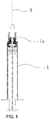
- the front end of the syringe tube (1) of the safety syringe is provided with the connecting tube (1 a); the outer diameter of the connecting tube (1a) is slightly smaller than that of the syringe tube (1); the front end of the syringe needle base (2) is connected to the syringe needle (3).
- the syringe needle base (2) is sleeved with the connecting tube (1 a), and the two are connected with each other.
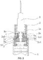
- the connecting structure for the syringe needle base and the syringe tube comprises the elastic connecting pieces (2a) arranged at the rear end of the syringe needle base (2) and first connecting parts (1a1) arranged at the inner side of the connecting tube (1a); the outer sides of the connecting pieces (2a) are provided with the second connecting parts (2a1); the syringe needle base (2) is sleeved with the connecting tube (1 a), and the first connecting parts (1a1) are clamped with the second connecting parts (2a1).
- the first connecting parts (1a1) are the protruding blocks (6a) which protrude out of the inner side of the connecting tube (1a);
- the second connecting parts (2a1) are grooves (6b) which sink into the outer side of the connecting pieces (2a);
- the grooves (6b) are matched with the protruding blocks (6a), and the protruding blocks (6a) are embedded into the grooves (6b).
- the positions of the protruding blocks (6a) and the grooves (6b) can be swapped, in another word, the first connecting parts (1a1) are the grooves which sink into the inner side of the connecting tube (1a), and the second connecting parts (2a1) are the protruding blocks (6a) which protrude out of the outer side of the connecting pieces (2a) and are matched with the grooves (6b).
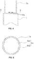
- the number of the protruding blocks (6a) is two, and the two protruding blocks (6a) are symmetrically distributed on the two sides in the connecting tube (1a); the number of the connecting pieces (2a) is two, and each connecting piece (2a) is provided with one groove (6b); the protruding blocks (6a) are matched with the grooves (6b) in a one-to-one corresponding mode.
- Each protruding block (6a) is formed by adjacent first protruding block (6a1) and second protruding block (6a2), in another word, four connecting points are provided for the positions where the syringe needle base (2) are connected with the connecting tube (1 a).
- the number of minor protruding blocks on each protruding block (6a) can be increased, and the number of grooves on the corresponding connecting piece (2a) can be increased as well.
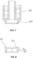
- the upper edges, facing the end of the connecting tube (1 a), of the protruding blocks (6a) are first inclined faces (7a); the upper edges of the grooves (6b) in the connecting pieces (2a) are second inclined faces (7b); the direction of inclination of the second inclined faces (7b) of the upper edges of the grooves (6b) is the same as that of the first inclined faces (7a) of the upper edges of the protruding blocks (6a) and the angles of inclination are the same as well.
- the syringe needle base (2) is provided with a cylinder-shaped expanding part (5); a limiting structure which is capable of moving the expanding part (5) up and down within the set range is arranged between the upper end of the expanding part (5) and the connecting pieces (2a); the outer side at the lower end of the expanding part (5) is provided with a pushing part (5a) which is used for expanding the connecting pieces (2a) towards the inner side of the connecting tube (1 a); the outer diameter of the pushing part (5a) is greater than the size between the two connecting pieces (2a).
- an inclined guiding face (5b) is arranged between the pushing part (5a) and the expanding part (5).
- the limiting structure comprises a convex annular first protruding ring (2a3) arranged at the inner side of the connecting pieces (2a) and a convex annular second protruding ring (5c) arranged at the outer side of the expanding part (5); the second protruding ring (5c) is positioned between the end of the syringe needle base (2) and the first protruding ring (2a3), and the first protruding ring (2a3) can be abutted against the second protruding ring (5c).
- the limiting structure comprises limiting grooves which sink into the inner side of the connecting pieces (2a) and inserting rods which protrude out of the outer side of the expanding part (5); the inserting rods are positioned in the limiting grooves.
- a sealing ring (4) is arranged between the syringe needle base (2) and the syringe tube (1).
- the connecting pieces (2a) When the expanding part (5) is positioned in the connecting pieces (2a) and exerts the outward expanding force onto the connecting pieces (2a), the connecting pieces (2a) are in an outward inclined state, the ends of the connecting pieces (2a) partially protrude out of the outer side of the syringe needle base (2).
- a gap exists between the syringe needle base (2) and the connecting tube (1 a), and the second connecting parts (2a1) are close to the ends of the connecting pieces (2a).
- the outer side at the middle of the syringe needle base (2) is provided with a sealing ring groove (2a2); the sealing ring (4) is positioned in the sealing ring groove (2a2), and the sealing ring (4) is tightly pressed between the syringe needle base (2) and the connecting tube (1 a).
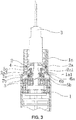
- the syringe needle base (2) comprises a first base body (2b) and a second base body (2c); the first base body (2b) is connected with the syringe needle (3); the connecting pieces (2a) are positioned at the end of the second base body (2c).
- the outer side at the lower end of the first base body (2b) is provided with a concave ring-shaped connecting groove (2b1);
- the second base body (2c) is in the shape of a barrel, and the inner side of the second base body (2c) is provided with a protruding ring-shaped connecting ring (2c1);
- the first base body (2b) is sleeved with the second base body (2c), and the connecting ring (2c1) is embedded into the connecting groove (2b1).
- the concave ring-shaped sealing ring groove (2a2) is formed between the first base body (2b) and the outer side of the second base body (2c); the sealing ring (4) is positioned in the sealing ring groove (2a2), see FIGs.6 , 7, and 8 .
- the syringe needle base (2) When the first connecting part (1a1) and the second connecting part (2a1) in this structure are clamped with each other, the syringe needle base (2) can be connected with the connecting tube (1 a). Due to the fact that the first connecting parts (1a1) are clamped with the second connecting parts (2a1), connecting the syringe needle base (2) with the connecting tube (1a) can further prevent the syringe needle base (2) from rotating relative to the connecting tube (1a).
- the syringe needle (3) when the syringe needle (3) is connected to the syringe needle base (2), due to the fact that the syringe needle base (2) dose not rotate, the syringe needle (3) can be conveniently connected to the syringe needle base (2) by applying the rotational force, and the syringe needle (3) of the syringe is firmly connected with the syringe needle base (2) after the assembling is completed.
- the pushing part (5a) of the expanding part (5) is abutted against the inner side of the connecting pieces (2a); the outer sides of the connecting pieces (2a) are abutted against the inner side of the connecting tube (1 a) under the expanding effect of the expanding part (5), and finally the first connecting parts (1a1) are firmly clamped with the second connecting parts (2a1).
- the syringe needle base (2) does not retract into the syringe tube (1) when the syringe is used normally.
- the syringe needle base (2) is positioned at the end of the syringe tube (1); the syringe needle (3) is connected to the inside of the syringe needle base (2) in a threaded mode; the expanding part (5) is positioned at the inner sides of the connecting pieces (2a); the syringe needle base (2) enables the connecting pieces (2a) to be clamped with the connecting tube (1a) through the effect of the expanding part (5) acted onto the connecting pieces (2a); therefore, the syringe needle base (2) is connected with the syringe tube (1).
- a pushing rod of the piston rod pulls the expanding part (5) to move downward through a pulling part formed by the stepped face; after the expanding part (5) is moved downward, the pushing part (5a) of the expanding part (5) is detached from the inner sides of the connecting pieces (2a); the connecting pieces (2a) retract under the effect of their own elastic force, and the outer sides of the connecting pieces (2a) are detached from the connecting tube (1a).
- the first connecting parts (1a1) are also detached from the second connecting parts (2a1) at this moment.
- the expanding part (5) which is moved downward will not be detached from the syringe needle base (2), and after pulling the pushing rod continuously, the syringe needle base (2) is finally pulled into the syringe tube (1) so that the self-destruction is achieved.
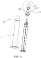
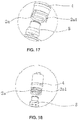
- This second preferred embodiment is essentially identical to the first embodiment in terms of the structure and principles, but the differences are: the annular first connecting parts (1a1) protrude out of the inner side of the connecting tube (1 a); the connecting piece (2a) is in the shape of an arc which is matched with the inner side of the connecting tube (1 a); the second connecting parts (2a1) are arc-shaped grooves which sink into the outer sides connecting pieces (2a), see FIGs.11 , 12 , 13 , 15 , and 18 .
- the number of the connecting pieces (2a) in this embodiment can be two or more.
- this third preferred embodiment is essentially identical to the first embodiment or the second embodiment in terms of the structure and principles, but the differences are: in this embodiment, the syringe needle base (2) is integrally formed; the syringe needle base (2) and the syringe needle (3) are all connected as a whole; the connecting pieces (2a) are positioned at the rear end of the syringe needle base (2); the outer side of the syringe needle base (2) is provided with a concave ring-shaped sealing ring groove (2a2); the sealing ring (4) is embedded into the sealing ring groove (2a2).
Landscapes
- Health & Medical Sciences (AREA)
- Engineering & Computer Science (AREA)
- Hematology (AREA)
- Anesthesiology (AREA)
- Biomedical Technology (AREA)
- Heart & Thoracic Surgery (AREA)
- Vascular Medicine (AREA)
- Life Sciences & Earth Sciences (AREA)
- Animal Behavior & Ethology (AREA)
- General Health & Medical Sciences (AREA)
- Public Health (AREA)
- Veterinary Medicine (AREA)
- Infusion, Injection, And Reservoir Apparatuses (AREA)
- Environmental & Geological Engineering (AREA)
Applications Claiming Priority (2)
| Application Number | Priority Date | Filing Date | Title |
|---|---|---|---|
| CN201310724627.7A CN103638582B (zh) | 2013-12-25 | 2013-12-25 | 一种安全注射器中针头座与针筒的连接结构 |
| PCT/CN2014/090686 WO2015096560A1 (fr) | 2013-12-25 | 2014-11-10 | Structure de raccordement entre un siège d'aiguille et une seringue dans un injecteur de sécurité |
Publications (2)
| Publication Number | Publication Date |
|---|---|
| EP3088028A1 true EP3088028A1 (fr) | 2016-11-02 |
| EP3088028A4 EP3088028A4 (fr) | 2017-08-23 |
Family
ID=50243951
Family Applications (1)
| Application Number | Title | Priority Date | Filing Date |
|---|---|---|---|
| EP14875487.2A Withdrawn EP3088028A4 (fr) | 2013-12-25 | 2014-11-10 | Structure de raccordement entre un siège d'aiguille et une seringue dans un injecteur de sécurité |
Country Status (6)
| Country | Link |
|---|---|
| US (1) | US20160317758A1 (fr) |
| EP (1) | EP3088028A4 (fr) |
| CN (1) | CN103638582B (fr) |
| AU (1) | AU2014373195B2 (fr) |
| RU (1) | RU2648036C1 (fr) |
| WO (1) | WO2015096560A1 (fr) |
Families Citing this family (6)
| Publication number | Priority date | Publication date | Assignee | Title |
|---|---|---|---|---|
| CN103638582B (zh) * | 2013-12-25 | 2015-09-30 | 徐雪花 | 一种安全注射器中针头座与针筒的连接结构 |
| TWI564048B (zh) * | 2015-06-17 | 2017-01-01 | Qing-Xiang Wei | Push the unloading needle safety syringe |
| US20170028138A1 (en) * | 2015-07-28 | 2017-02-02 | Ching Hsiang Wei | Push-and-separate safety syringe |
| RU184811U1 (ru) * | 2018-08-02 | 2018-11-12 | Рамазан Мусаевич Файзиев | Саморазрушающийся шприц с втягивающейся иглой, исключающий возможность повторного применения |
| CN109908433B (zh) * | 2018-12-05 | 2022-02-08 | 王琳 | 一次性微量高精度安全注射器 |
| CN111658898B (zh) * | 2020-07-22 | 2022-07-22 | 徐立 | 自毁式安全注射器 |
Family Cites Families (16)
| Publication number | Priority date | Publication date | Assignee | Title |
|---|---|---|---|---|
| CN1238067C (zh) * | 2001-09-13 | 2006-01-25 | 名高生化科技股份有限公司 | 安全注射器的针头座 |
| US6821266B2 (en) * | 2002-11-12 | 2004-11-23 | U.S. Technology, Inc. | Syringe |
| SE0301667D0 (sv) * | 2003-06-04 | 2003-06-04 | Medsafe Asa | Disposable injection syringe |
| US7637890B2 (en) * | 2005-01-25 | 2009-12-29 | Zuoqian Lin | Safety self-destroying disposable syringe |
| CN2794529Y (zh) * | 2005-03-04 | 2006-07-12 | 美国赛伦杰医疗器械公司 | 安全自毁注射器 |
| EA013153B1 (ru) * | 2005-09-06 | 2010-02-26 | Глобал Медисэйф Холдингз Лимитед | Одноразовый безопасный шприц со втягивающейся иглой |
| CN100522269C (zh) * | 2006-08-08 | 2009-08-05 | 林作钱 | 一种针头回缩式安全注射器 |
| GB2470935A (en) * | 2009-06-11 | 2010-12-15 | David Howell Jenkins | Single use syringe hub with moveable bung |
| CN201469833U (zh) * | 2009-07-30 | 2010-05-19 | 林作钱 | 一种改进的安全注射器 |
| CN101850144B (zh) | 2010-06-18 | 2012-07-25 | 徐雪花 | 安全自毁式注射器 |
| US9878101B2 (en) * | 2010-11-12 | 2018-01-30 | Sio2 Medical Products, Inc. | Cyclic olefin polymer vessels and vessel coating methods |
| CN102327658B (zh) * | 2011-10-20 | 2013-01-16 | 柏保东 | 装配方便的高安全自毁式注射器 |
| CN202236714U (zh) * | 2011-10-20 | 2012-05-30 | 柏保东 | 装配方便的高安全自毁式注射器 |
| CN202777325U (zh) * | 2012-07-17 | 2013-03-13 | 浙江玉升医疗器械股份有限公司 | 一种回缩式自毁注射器 |
| CN103638582B (zh) * | 2013-12-25 | 2015-09-30 | 徐雪花 | 一种安全注射器中针头座与针筒的连接结构 |
| CN203694276U (zh) * | 2013-12-25 | 2014-07-09 | 徐雪花 | 一种安全注射器中针头座与针筒的连接结构 |
-
2013
- 2013-12-25 CN CN201310724627.7A patent/CN103638582B/zh active Active
-
2014
- 2014-11-10 RU RU2016126412A patent/RU2648036C1/ru active
- 2014-11-10 AU AU2014373195A patent/AU2014373195B2/en not_active Ceased
- 2014-11-10 US US15/107,463 patent/US20160317758A1/en not_active Abandoned
- 2014-11-10 EP EP14875487.2A patent/EP3088028A4/fr not_active Withdrawn
- 2014-11-10 WO PCT/CN2014/090686 patent/WO2015096560A1/fr active Application Filing
Also Published As
| Publication number | Publication date |
|---|---|
| AU2014373195A1 (en) | 2016-06-30 |
| CN103638582B (zh) | 2015-09-30 |
| WO2015096560A1 (fr) | 2015-07-02 |
| US20160317758A1 (en) | 2016-11-03 |
| AU2014373195B2 (en) | 2017-09-14 |
| RU2648036C1 (ru) | 2018-03-21 |
| EP3088028A4 (fr) | 2017-08-23 |
| CN103638582A (zh) | 2014-03-19 |
Similar Documents
| Publication | Publication Date | Title |
|---|---|---|
| AU2014373195B2 (en) | Connection structure between needle seat and syringe in safe injector | |
| EP2279771B1 (fr) | Nouvelle seringue non réutilisable à verrouillage sûr | |
| JP5993919B2 (ja) | 安全注射器 | |
| US20040082911A1 (en) | Syringe having needle safely receiving structure | |
| WO2009127122A1 (fr) | Seringue de sûreté | |
| US20120172799A1 (en) | Disposable safety syringe with retractable needle tip | |
| WO2006119667A1 (fr) | Seringue de securite jetable | |
| RU2534405C2 (ru) | Шприц с убирающейся иглой и режущей коронкой | |
| US6827704B1 (en) | Safety syringe | |
| CN113274585A (zh) | 一种安全注射器 | |
| CN203694276U (zh) | 一种安全注射器中针头座与针筒的连接结构 | |
| WO2007028296A1 (fr) | Seringue de securite | |
| KR102675223B1 (ko) | 다기능 바늘 홀더 및 리테이너 링 조립체를 가지는 주사기 | |
| TWM552355U (zh) | 安全針筒 | |
| CN107308524B (zh) | 一种快速自动注射装置 | |
| CN208355867U (zh) | 一种快速自动注射装置 | |
| CN217660976U (zh) | 一种安全注射器 | |
| WO2019029122A1 (fr) | Seringue rapide et automatique | |
| ITMI20030610U1 (it) | Dispositivo di sicurezza per la iniezione-campionatura di fluidi | |
| TWM411948U (en) | Structure to retract the needle head of safety injection needle cylinder | |
| TWM485055U (zh) | 安全針筒 | |
| TWI236918B (en) | Safety syringes with retractable needle | |
| CN102872505B (zh) | 一种弹簧式安全注射器 | |
| KR200431655Y1 (ko) | 간이식 안전주사기 | |
| TWI239255B (en) | Safe syringe |
Legal Events
| Date | Code | Title | Description |
|---|---|---|---|
| PUAI | Public reference made under article 153(3) epc to a published international application that has entered the european phase |
Free format text: ORIGINAL CODE: 0009012 |
|
| STAA | Information on the status of an ep patent application or granted ep patent |
Free format text: STATUS: REQUEST FOR EXAMINATION WAS MADE |
|
| 17P | Request for examination filed |
Effective date: 20160620 |
|
| AK | Designated contracting states |
Kind code of ref document: A1 Designated state(s): AL AT BE BG CH CY CZ DE DK EE ES FI FR GB GR HR HU IE IS IT LI LT LU LV MC MK MT NL NO PL PT RO RS SE SI SK SM TR |
|
| AX | Request for extension of the european patent |
Extension state: BA ME |
|
| DAX | Request for extension of the european patent (deleted) | ||
| A4 | Supplementary search report drawn up and despatched |
Effective date: 20170721 |
|
| RIC1 | Information provided on ipc code assigned before grant |
Ipc: A61M 5/32 20060101AFI20170717BHEP Ipc: A61M 5/34 20060101ALI20170717BHEP Ipc: A61M 5/50 20060101ALI20170717BHEP |
|
| STAA | Information on the status of an ep patent application or granted ep patent |
Free format text: STATUS: EXAMINATION IS IN PROGRESS |
|
| 17Q | First examination report despatched |
Effective date: 20210325 |
|
| STAA | Information on the status of an ep patent application or granted ep patent |
Free format text: STATUS: THE APPLICATION IS DEEMED TO BE WITHDRAWN |
|
| 18D | Application deemed to be withdrawn |
Effective date: 20210805 |