EP3087903A1 - Endoscope system and pixel correction method - Google Patents
Endoscope system and pixel correction method Download PDFInfo
- Publication number
- EP3087903A1 EP3087903A1 EP14873476.7A EP14873476A EP3087903A1 EP 3087903 A1 EP3087903 A1 EP 3087903A1 EP 14873476 A EP14873476 A EP 14873476A EP 3087903 A1 EP3087903 A1 EP 3087903A1
- Authority
- EP
- European Patent Office
- Prior art keywords
- image
- unit
- defective pixel
- light source
- image data
- Prior art date
- Legal status (The legal status is an assumption and is not a legal conclusion. Google has not performed a legal analysis and makes no representation as to the accuracy of the status listed.)
- Withdrawn
Links
Images





Classifications
-
- G—PHYSICS
- G02—OPTICS
- G02B—OPTICAL ELEMENTS, SYSTEMS OR APPARATUS
- G02B23/00—Telescopes, e.g. binoculars; Periscopes; Instruments for viewing the inside of hollow bodies; Viewfinders; Optical aiming or sighting devices
- G02B23/24—Instruments or systems for viewing the inside of hollow bodies, e.g. fibrescopes
- G02B23/2476—Non-optical details, e.g. housings, mountings, supports
- G02B23/2484—Arrangements in relation to a camera or imaging device
-
- A—HUMAN NECESSITIES
- A61—MEDICAL OR VETERINARY SCIENCE; HYGIENE
- A61B—DIAGNOSIS; SURGERY; IDENTIFICATION
- A61B1/00—Instruments for performing medical examinations of the interior of cavities or tubes of the body by visual or photographical inspection, e.g. endoscopes; Illuminating arrangements therefor
- A61B1/00002—Operational features of endoscopes
- A61B1/00004—Operational features of endoscopes characterised by electronic signal processing
- A61B1/00006—Operational features of endoscopes characterised by electronic signal processing of control signals
-
- A—HUMAN NECESSITIES
- A61—MEDICAL OR VETERINARY SCIENCE; HYGIENE
- A61B—DIAGNOSIS; SURGERY; IDENTIFICATION
- A61B1/00—Instruments for performing medical examinations of the interior of cavities or tubes of the body by visual or photographical inspection, e.g. endoscopes; Illuminating arrangements therefor
- A61B1/00002—Operational features of endoscopes
- A61B1/00004—Operational features of endoscopes characterised by electronic signal processing
- A61B1/00009—Operational features of endoscopes characterised by electronic signal processing of image signals during a use of endoscope
-
- A—HUMAN NECESSITIES
- A61—MEDICAL OR VETERINARY SCIENCE; HYGIENE
- A61B—DIAGNOSIS; SURGERY; IDENTIFICATION
- A61B1/00—Instruments for performing medical examinations of the interior of cavities or tubes of the body by visual or photographical inspection, e.g. endoscopes; Illuminating arrangements therefor
- A61B1/04—Instruments for performing medical examinations of the interior of cavities or tubes of the body by visual or photographical inspection, e.g. endoscopes; Illuminating arrangements therefor combined with photographic or television appliances
- A61B1/05—Instruments for performing medical examinations of the interior of cavities or tubes of the body by visual or photographical inspection, e.g. endoscopes; Illuminating arrangements therefor combined with photographic or television appliances characterised by the image sensor, e.g. camera, being in the distal end portion
-
- A—HUMAN NECESSITIES
- A61—MEDICAL OR VETERINARY SCIENCE; HYGIENE
- A61B—DIAGNOSIS; SURGERY; IDENTIFICATION
- A61B1/00—Instruments for performing medical examinations of the interior of cavities or tubes of the body by visual or photographical inspection, e.g. endoscopes; Illuminating arrangements therefor
- A61B1/06—Instruments for performing medical examinations of the interior of cavities or tubes of the body by visual or photographical inspection, e.g. endoscopes; Illuminating arrangements therefor with illuminating arrangements
- A61B1/07—Instruments for performing medical examinations of the interior of cavities or tubes of the body by visual or photographical inspection, e.g. endoscopes; Illuminating arrangements therefor with illuminating arrangements using light-conductive means, e.g. optical fibres
-
- H—ELECTRICITY
- H04—ELECTRIC COMMUNICATION TECHNIQUE
- H04N—PICTORIAL COMMUNICATION, e.g. TELEVISION
- H04N23/00—Cameras or camera modules comprising electronic image sensors; Control thereof
- H04N23/70—Circuitry for compensating brightness variation in the scene
- H04N23/74—Circuitry for compensating brightness variation in the scene by influencing the scene brightness using illuminating means
-
- H—ELECTRICITY
- H04—ELECTRIC COMMUNICATION TECHNIQUE
- H04N—PICTORIAL COMMUNICATION, e.g. TELEVISION
- H04N25/00—Circuitry of solid-state image sensors [SSIS]; Control thereof
- H04N25/60—Noise processing, e.g. detecting, correcting, reducing or removing noise
- H04N25/68—Noise processing, e.g. detecting, correcting, reducing or removing noise applied to defects
Definitions
- the present invention relates to an endoscope system configured to be introduced into a living body to capture an image inside the living body, and a pixel correction method for correcting a pixel of an image sensor provided at the endoscope system.
- a solid state image sensor such as a charge coupled device (CCD) and a complementary metal oxide semiconductor (CMOS) is formed of a plurality of pixels that outputs electric signals by receiving light and photoelectrically converting the light.
- CCD charge coupled device
- CMOS complementary metal oxide semiconductor
- Kinds of such defective pixels may include: a constant defective pixel that constantly outputs an abnormal electric signal due to dust adhesion to a light receiving surface, a device crystal defect, and the like; and a blinking defective pixel that irregularly outputs an abnormal electric signal due to noise of a random telegraph signal (RTS) generated by current disorder caused by a fact that electrons moving inside a MOS transistor are captured by a trap level existing in a gate insulator film due to miniaturization of the solid state image sensor.
- RTS random telegraph signal
- the blinking defective pixel appears on a captured image as image noise irregularly generated while a moving image is photographed.
- a technology to remove such image noise there is a known technology in which the solid state image sensor is made to capture images a plurality of times in a state that an image sensor is blocked from the light, and a blinking defective pixel is detected from a plurality of captured images, and then an electric signal of the detected blinking defective pixel is corrected (refer to Patent Literature 1).
- Patent Literature 1 Japanese Laid-open Patent Publication No. 2013-211785
- the present invention has been made in view of the foregoing, and an object of the invention is to provide an endoscope system and a pixel correcting method that are able to surely detect and correct a blinking defective pixel in an image sensor.
- an endoscope system includes: a light source unit configured to emit illumination light to illuminate a subject; an image sensor having a plurality of pixels arranged two-dimensionally, each of the plurality of pixels being configured to receive light and perform photoelectric conversion on the received light to output an electric signal, and the image sensor being configured to image the object at a predetermined frame rate and output image data of the subject; an illumination controller configured to turn off the light source unit in a predetermined cycle; a difference calculation unit configured to calculate difference data between a dark image and a dark reference image, the dark image corresponding to the image data output from the image sensor during lights-out time when the illumination controller turns off the light source unit, and the dark reference image having been preliminarily generated to detect a blinking defective pixel in which the electric signal irregularly changes; a blinking defective pixel detection unit configured to detect the blinking defective pixel in the image sensor based on the difference data calculated by the difference calculation unit; and a pixel correction unit configured to correct
- the endoscope system further includes: a display device configured to display an image corresponding to the image data generated by the image sensor; and an image output timing adjustment unit configured to temporarily hold the image data generated by the image sensor, and output the image data to the display device at predetermined timing. If the illumination controller turns off the light source unit n times (n ⁇ 1) per unit time and the predetermined frame rate is set to N, the illumination controller is configured to turn off the light source unit such that the lights-out time of the light source unit per frame is 1/N, and the image output timing adjustment unit is configured to output the image data to the display device at a frame rate of the N-n.
- the illumination controller is configured to turn off the light source unit in a first frame per unit time.
- the illumination controller is configured to set a frame of a lights-out period during which the light source unit is turned off, to be equal to or longer than a frame of a lighting period during which the light source unit is turned on.
- the light source unit includes an LED light source.
- the dark reference image is obtained by averaging a plurality of dark images subsequently generated by the image sensor at the time of shipping the endoscope system or at the time of examination in which the endoscope system is inserted into a body cavity of the subject in use.
- the endoscope system further includes a capsule-shaped casing configured to be inserted into a body cavity of the subject.
- the light source unit, the image sensor, the illumination controller, the difference calculation unit, the blinking defective pixel detection unit, and the pixel correction unit are provided inside the casing.
- a pixel correction method is executed by an endoscope system.
- the method includes: an emitting step of emitting illumination light to illuminate an object; an imaging step of causing an image sensor to image the object at a predetermined frame rate and output image data of the object, the image sensor having a plurality of pixels arranged two-dimensionally, each of the plurality of pixels being configured to receive light and perform photoelectric conversion on the received light to output an electric signal; an illumination control step of turning off the illumination light in a predetermined cycle; a difference calculation step of calculating difference data between a dark image and a dark reference image, the dark image corresponding to the image data output in the imaging step during lights-out time when the illumination light is turned off in the illumination control step, and the dark reference image having been preliminarily generated to detect a blinking defective pixel in which the electric signal irregularly changes; a blinking defective pixel detection step of detecting the blinking defective pixel in the image sensor based on the difference data calculated in the difference calculation step; and a pixel correction step of correcting
- FIG. 1 is a diagram illustrating a brief structure of an endoscope system according to a first embodiment of the present invention.
- FIG. 2 is a block diagram illustrating a functional configuration of a main portion of the endoscope system according to the first embodiment of the present invention.
- An endoscope system 1 illustrated in FIGS. 1 and 2 includes an endoscopic device 2 (electronic scope) that captures an in-vivo image of a subject by inserting a distal end portion of the endoscopic device into a body cavity of the subject; a light source device 3 that generates illumination light to illuminate an object from the distal end of the endoscopic device 2; a display device 4 that can display the in-vivo image captured by the endoscopic device 2; and a processing device 5 (external processor) that applies predetermined image processing to the in-vivo image captured by the endoscopic device 2, outputs the same to the display device 4, and further integrally controls operation of the entire endoscope system 1.
- an endoscopic device 2 electronic scope
- a light source device 3 that generates illumination light to illuminate an object from the distal end of the endoscopic device 2
- a display device 4 that can display the in-vivo image captured by the endoscopic device 2
- a processing device 5 external processor
- the endoscopic device 2 includes: an insertion portion 21 having flexibility and formed in a thin long shape; an operating unit 22 connected to a proximal end side of the insertion portion 21 and adapted to receive various kinds of operation signal input; and a universal cord 23 extending from the operating unit 22 in a direction different from an extending direction of the insertion portion 21, and incorporating various kinds of cables to connect the light source device 3 and the processing device 5.
- the insertion portion 21 includes: a distal end portion 24 incorporating an image sensor described later; a bending portion 25 formed of a plurality of bending pieces and capable of being freely bent; and a flexible tube portion 26 connected to a proximal end side of the bending portion 25, having flexibility, and formed in a long shape.
- the distal end portion 24 includes: a light guide 241 formed by using glass fibers and the like and constituting a light guide passage for the light emitted from the light source device 3; an illumination lens 242 provided at a distal end of the light guide 241; an optical system 243 for light condensing; an image sensor 244 disposed at an image forming position of the optical system 243 and having a plurality of pixels two-dimensionally arrayed and adapted to photoelectrically convert, to an electric signal, the light condensed by the optical system 243; an endoscopic recording unit 245 that records various kinds of information related to the endoscopic device 2; and an imaging controller 246 that controls the image sensor 244.
- the optical system 243 is formed by using one or plurality of lenses and moved along an apical axis L, thereby performing optical zooming to change a viewing angle and changing a focal point.
- the image sensor 244 has the plurality of pixels that is two-dimensionally arrayed and outputs an electric signal by receiving light and photoelectrically converting the light, and the image sensor captures an image of the object (body cavity) at a predetermined frame rate and outputs image data of the object. More specifically, the image sensor 244 is formed by using an image sensor such as a charge coupled device (CCD) or a complementary metal oxide semiconductor (CMOS) in which a plurality of pixels is arrayed in a two-dimensional matrix, and each of the pixels includes: a photodiode to accumulate electric charge corresponding to a light amount; and an amplifier to amplify the electric charge accumulated by the photodiode. The image sensor 244 outputs the electric signal generated by each of the pixels as image data (RAW data) to the processing device 5.
- CMOS complementary metal oxide semiconductor
- the endoscopic recording unit 245 records various kinds of information related to the endoscopic device 2 such as identification information to identify the endoscopic device 2 and identification information of the image sensor 244.
- the endoscopic recording unit 245 is formed by using a non-volatile memory and the like.
- the imaging controller 246 controls operation of the image sensor 244 based on command information received from the processing device 5. More specifically, the imaging controller 246 controls a frame rate of the image sensor 244 based on the command information received from the processing device 5. For example, the imaging controller 246 controls the image sensor 244 to output image data at 60 fps.
- the operating unit 22 includes: a bending knob 221 to bend the bending portion 25 in a vertical direction and a horizontal direction; a treatment tool insertion portion 222 to insert a treatment tool, such as a living body forceps, a laser scalpel, or a TEST probe, into a body cavity; and a plurality of switches 223, namely, an operation input unit to input operation command signals for peripheral apparatuses such as an air feeding means, a water feeding means, and a gas feeding means in addition to the light source device 3 and processing device 5.
- a treatment tool inserted from the treatment tool insertion portion 222 is passed through a treatment instrument channel (not illustrated) at the distal end portion 24, and comes out from an opening (not illustrated).
- the universal cord 23 incorporates at least the light guide 241 and a light collecting cable formed by assembling one or a plurality of cables.
- the cable assembly includes signal lines through which signals are transmitted and received between the endoscopic device 2, light source device 3, and processing device 5. Examples of the signal lines include a signal line for transmitting and receiving setting data, a signal line for transmitting and receiving an image signal, and a signal line for transmitting and receiving a drive timing signal to drive the image sensor 244.
- the universal cord 23 includes a connector portion 27 detachably attached to the light source device 3.
- the connector portion 27 is provided with a coil cable 27a having a coil shape in an extending manner. At an extending end of the coil cable 27a, a connector portion 28 detachably attached to the processing device 5 is provided.
- the light source device 3 includes a light source unit 31, a light source driver 32, and an illumination controller 33.
- the light source unit 31 emits illumination light to illuminate a subject.
- the light source unit 31 includes a condenser lens 311 and a light source 312.
- the condenser lens 311 is formed by using one or a plurality of lenses and condenses light emitted from the light source 312.
- the light source 312 is formed by using a light emitting diode (LED) and generates white light. Note that the light source 312 may also be formed by using a red LED, a green LED, and a blue LED, and may generate white light by simultaneously emitting the respective LEDs.
- LED light emitting diode
- the light source driver 32 intermittently causes the light source 312 to generate white light by supplying the light source 312 with electricity under control of the illumination controller 33.
- the light emitted from the light source 312 is emitted from a distal end of the distal end portion 24 via the condenser lens 311 and the light guide 241.
- the illumination controller 33 controls lighting timing of the light source 312 based on a command signal received from the processing device 5. Specifically, the illumination controller 33 turns off the light source 312 in a predetermined cycle. More specifically, in the case where the illumination controller 33 turns off the light source unit 31 n times (n ⁇ 1) per unit time and further a frame rate of image data generated by the image sensor 244 is N, the illumination controller 33 also turns off the light source unit 31 by setting a lights-out time of the light source unit 31 to 1/N.
- the illumination controller 33 turns off the light source 312 during one frame only and further turns off the light source unit 31 by setting the lights-out time to 1/61 (sec).
- the illumination controller 33 is formed by using a CPU or the like.
- the display device 4 displays an in-vivo image received from the processing device 5. Further, the display device 4 displays the various kinds of information related to the endoscope system 1.
- the display device 4 is formed by using a liquid crystal, an organic electro luminescence (EL) or the like.
- the processing device 5 includes an image acquisition unit 51, a difference calculation unit 52, a blinking defective pixel detection unit 53, a recording unit 54, an image output timing adjustment unit 55, an image processing unit 56, a reference clock generation unit 57, and a processing controller 58.
- the image acquisition unit 51 acquires image data generated by the image sensor 244. More specifically, the image acquisition unit 51 acquires the image data from the image sensor 244 at a predetermined frame rate under the control of the processing controller 58. Further, in the case where the image data acquired from the image sensor 244 under the control of the processing controller 58 is normal exposure image data captured under normal exposure, the image acquisition unit 51 outputs the image data to the image output timing adjustment unit 55. On the other hand, in the case where the image data acquired from the image sensor 244 is dark image data, the image acquisition unit 51 outputs the dark image data to the difference calculation unit 52.
- the difference calculation unit 52 calculates difference data (difference value) between a dark image corresponding to the dark image data received from the image acquisition unit 51 and a dark reference image corresponding to dark reference image data recorded in a later-described dark reference image data recording unit 542 of the recording unit 54, and outputs a calculation result thereof to the blinking defective pixel detection unit 53. More specifically, the difference calculation unit 52 calculates difference data of a pixel value (electric signal) per pixel between the dark image and the dark reference image, and outputs the calculation result to the blinking defective pixel detection unit 53.
- the blinking defective pixel detection unit 53 detects a blinking defective pixel in the image sensor 244 based on the difference data received from the difference calculation unit 52. More specifically, the blinking defective pixel detection unit 53 determines whether a pixel value is a predetermined threshold value or more as for the difference data per pixel received from the difference calculation unit 52, and detects a pixel having the pixel value of the predetermined threshold value or more as a blinking defective pixel. The blinking defective pixel detection unit 53 outputs, to a correction pixel information recording unit 541, positional information (pixel address) of the detected blinking defective pixel on the image sensor 244.
- the recording unit 54 records various kinds of programs to operate the endoscope system 1, various kinds of parameters and the like needed in operation of the endoscope system 1. Further, the recording unit 54 includes: the correction pixel information recording unit 541 to record positional information of a defective pixel and positional information of a blinking defective pixel in the image sensor 244; and a dark reference image data recording unit 542 to record the dark reference image data used at the time of detecting the blinking defective pixel.
- the dark reference image data is obtained by averaging a plurality of dark image data before shipment of the endoscopic device 2 or at the time of starting operation of the endoscope system 1. In this dark reference image data, defective pixel information is included.
- the recording unit 54 is formed by using a recording medium such as a synchronous dynamic random access memory (SDRAM), a flash memory, or the like, and a hard disk drive (HDD).
- SDRAM synchronous dynamic random access memory
- HDD hard disk drive
- the image output timing adjustment unit 55 temporarily holds normal image data received from the image acquisition unit 51 and outputs the normal image data to the image processing unit 56 at predetermined timing under the control of the processing controller 58. More specifically, in the case where the frame rate of the image data generated by the image sensor 244 is N, the image output timing adjustment unit 55 executes outputting by setting a frame rate to N - n when the normal image data received from the image sensor 244 via the image acquisition unit 51 is output to the image processing unit 56.
- the image output timing adjustment unit 55 outputs the normal image data sequentially received from the image sensor 244 to the image processing unit 56 at 60 fps via the image acquisition unit 51.
- the image processing unit 56 applies various kinds of image processing to the image data received from the image output timing adjustment unit 55, and outputs the image data to the display device 4. More specifically, the image processing unit 56 applies, to the image data, at least image processing including such as optical black (OB) subtraction processing to correct black output, white balance (WB) adjustment processing to adjust color tone of the image data, color matrix operation processing, gamma correction processing, color reproduction processing, and edge enhancement processing. Further, the image processing unit 56 includes a pixel correction unit 561.
- OB optical black
- WB white balance
- the image processing unit 56 includes a pixel correction unit 561.
- the pixel correction unit 561 performs correction processing to correct respective electric signals of a defective pixel and a blinking defective pixel by using electric signals of neighboring pixels and adjacent pixels of the defective pixel and the blinking defective pixel based on defective pixel information and blinking defective pixel information recorded in the correction pixel information recording unit 541 of the recording unit 54.
- the reference clock generation unit 57 generates a reference clock signal to be reference of operation in each of the units in the endoscope system 1, and supplies the generated reference clock signal to each of the units in the endoscope system 1.
- the processing controller 58 executes: drive control for each of the units including the endoscopic device 2 and the light source device 3; and input/output control for information relative to each of the units.
- the processing controller 58 is formed by using a CPU and the like.
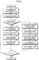
- FIG. 3 is a flowchart illustrating an outline of the processing executed by the endoscope system 1.
- the image sensor 244 starts imaging at a predetermined frame rate and further the light source device 3 starts illumination light emission in synchronization with the frame rate of the image sensor 244 (Step S101). More specifically, the imaging controller 246 makes the image sensor 244 start image capturing at the predetermined frame rate. For example, as illustrated in FIG. 4 , the imaging controller 246 makes the image sensor 244 start image capturing inside a body cavity of a subject at 61 fps. Further, the illumination controller 33 turns off the light source 312 in a predetermined cycle in synchronization with the frame rate of the image sensor 244. For example, as illustrated in FIG.
- the illumination controller 33 turns off the light source 312 at the first frame.
- the image sensor 244 generates dark image data.
- a pixel G1 indicates a defective pixel
- a pixel G2 indicates a blinking defective pixel in each of images F1 to F61 in FIG. 4 .
- a case where the blinking defective pixel outputs a normal image signal is indicated by hatching
- a case of outputting an abnormal image signal is indicated by white space on a colored background.
- FIG. 4 illustrates a state in which the blinking defective pixels G2 are generated on a dark image F1 in the first frame, a normal exposure image F2 in the second frame, and a normal exposure image F61 in the 61 th frame.
- the image acquisition unit 51 acquires image data generated by the image sensor 244 (Step S102).
- the processing controller 58 determines whether the image data acquired by the image acquisition unit 51 from the image sensor 244 is the dark image data (Step S103). More specifically, the processing controller 58 determines whether the image data acquired by the image acquisition unit 51 from the image sensor 244 is the image data generated by the image sensor 244 during the lights-out time when the light source 312 is turned off by the illumination controller 33. In the case where the processing controller 58 determines that the image data acquired by the image acquisition unit 51 from the image sensor 244 is the dark image data (Step S103: Yes), the endoscope system 1 proceeds to Step S104 described later. In contrast, in the case where the processing controller 58 determines that the image data acquired by the image acquisition unit 51 from the image sensor 244 is not the dark image data (Step S103: No), the endoscope system 1 proceeds to Step S108 described later.
- Step S104 the processing controller 58 controls the dark image data acquired by the image acquisition unit 51 from the image sensor 244 to be output to the difference calculation unit 52.
- the difference calculation unit 52 calculates the difference data based on the dark image corresponding to the dark image data received from the image acquisition unit 51 and the dark reference image corresponding to the dark reference image data recorded in the dark reference image data recording unit 542 (Step S105).
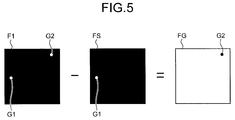
- FIG. 5 is a schematic diagram to describe a calculation method of the difference data calculated by the difference calculation unit 52.
- the difference calculation unit 52 calculates, per pixel, difference data FG of a pixel value (image signal) between a dark image F1 and a dark reference image FS by subtracting the dark reference image FS from the dark image F1.
- pixel value of the blinking defective pixel G2 is indicated by a black circle for clarification in FIG. 5 .
- the blinking defective pixel detection unit 53 detects a blinking defective pixel in the image sensor 244 based on the difference data calculated by the difference calculation unit 52 (Step S106). More specifically, the blinking defective pixel detection unit 53 determines whether the pixel value of the difference data calculated per pixel by the difference calculation unit 52 exceeds a predetermined threshold value, and detects a pixel exceeding the predetermined threshold value as a blinking defective pixel to be corrected. For example, in the case illustrated in FIG. 5 , the blinking defective pixel detection unit 53 detects the blinking defective pixel G2 of the difference data FG.
- the processing controller 58 records, in the correction pixel information recording unit 541, the blinking defective pixel information related to a position of the blinking defective pixel in the image sensor 244 detected by the blinking defective pixel detection unit 53 (Step S107). After Step S107, the endoscope system 1 proceeds to Step S113 described later.
- Step S108 the processing controller 58 outputs, to the image output timing adjustment unit 55, the normal exposure image data acquired by the image acquisition unit 51 from the image sensor 244.
- the image output timing adjustment unit 55 temporarily stores (holds) the normal exposure image data received from the image acquisition unit 51 (Step S109).
- the image output timing adjustment unit 55 outputs the normal exposure image data to the image processing unit 56 at the predetermined timing (Step S110). More specifically, the image output timing adjustment unit 55 outputs the normal exposure image data to the image processing unit 56 at a frame rate so as to be the same frame rate generated by the image sensor 244 per unit time. For example, the image output timing adjustment unit 55 outputs the normal exposure image data to the image processing unit 56 at 60 fps.
- the pixel correction unit 561 applies the pixel correction processing by using the electric signals of neighboring pixels to each of the defective pixel and the blinking defective pixel in the normal exposure image corresponding to the normal exposure image data received from the image output timing adjustment unit 55 based on the defective pixel information and the blinking defective pixel information recorded in the correction pixel information recording unit 541 (Step S111). More specifically, the pixel correction unit 561 corrects, as illustrated in FIG.
- the defective pixels G1 and the blinking defective pixels G2 in the normal exposure images F2 to F61 sequentially received from the image output timing adjustment unit 55 by using the electric signals of the neighboring pixels of the defective pixel G1, for example, four pixels adjacent to the defective pixel G1 based on the defective pixel information and the defective pixel information recorded in the correction pixel information recording unit 541. Further, the pixel correction unit 561 corrects the blinking defective pixel G2 by using the electric signals of the adjacent pixels of the blinking defective pixel G2. Then, display images F1' to F60' corresponding to display image data are generated ( FIG. 6(a) ⁇ FIG. 6(b) ). In this case, the image processing unit 56 applies, to the normal exposure image data, basic image processing needed to develop the above-described normal exposure image data.
- the image processing unit 56 outputs the display image data to the display device 4 (Step S112).
- the display device 4 can sequentially display the display images F1' to F60' in which the pixels of the defective pixel G1 and the blinking defective pixel G2 are corrected, and high-resolution image can be displayed.
- the endoscope system 1 proceeds to Step S113.
- Step S113: Yes the endoscope system 1 finishes the processing.
- the endoscope system 1 returns to Step S102.
- high-resolution image can be displayed because the blinking defective pixel in the image sensor 244 can be surely detected and corrected.
- dark reference image data is recorded in a dark reference image data recording unit 542, but in the second embodiment, dark reference image data is generated while examining a subject or before examining a subject. More specifically, in the second embodiment, a light source unit is turned off in a predetermined cycle. Further, in the second embodiment, the dark reference image data is generated by: sequentially recording a plurality of dark image data generated by an image sensor at lights-out time of the light source unit; and averaging an electric signal per pixel. Therefore, in the following, a configuration of an endoscope system according to the second embodiment will be described first, and then processing executed by the endoscope system according to the second embodiment will be described. Note that elements same as an endoscope system 1 according to the above-described first embodiment will be denoted by the same reference signs, and a description therefor will be omitted.
- FIG. 7 is a block diagram illustrating functions of a main portion of the endoscope system according to the second embodiment of the present invention.
- An endoscope system 1a illustrated in FIG. 7 includes an endoscopic device 2, a light source device 3a, a display device 4, and a processing device 5a.
- the light source device 3a includes a light source unit 31, a light source driver 32, and an illumination controller 33a.
- the illumination controller 33a turns off the light source unit 31 in a predetermined cycle in synchronization with a frame rate of image data generated by an image sensor 244. More specifically, in the case where the illumination controller 33a turns off the light source unit 31 n times (n ⁇ 1) per unit time and further a frame rate of image data generated by the image sensor 244 is N, the illumination controller 33a also turns off the light source unit 31 by setting lights-out time of the light source unit 31 to 1/N. For example, in the case where a frame rate of image data generated by the image sensor 244 is 60 fps, the illumination controller 33a turns off a light source 312 during respective imaging periods of 1 frame, 11 frame, 21 frame, 31 frame, 41 frame, and 51 frame.
- the illumination controller 33a turns off the light source unit 31 by setting the lights-out time of the light source unit 31 per frame to 1/60 (sec). Further, for example, in the case where the frame rate of the image data generated by the image sensor 244 is 120 fps, the illumination controller 33a may also turn off the light source unit 31 during imaging periods of even numbered frames or odd numbered frames.
- the processing device 5a includes an image acquisition unit 51, a difference calculation unit 52, a blinking defective pixel detection unit 53, a recording unit 54, an image output timing adjustment unit 55, an image processing unit 56a, a reference clock generation unit 57, a processing controller 58, and an averaging processing unit 59.
- the image processing unit 56a includes a pixel correction unit 561 and an image interpolation unit 562.
- the image interpolation unit 562 In the case where receiving timing of normal exposure image data received from the image output timing adjustment unit 55 corresponds to a frame of dark image data, the image interpolation unit 562 generates normal exposure image data corresponding to the frame of the dark image data based on most recent normal exposure image data and current normal exposure image data, and outputs the same to the display device 4.
- the averaging processing unit 59 averages a plurality of dark image data sequentially received from the image acquisition unit 51 to generate the dark reference image data. More specifically, in the case where a distal end portion 24 of the endoscopic device 2 is inserted into a body cavity of a subject at the time of examining or while examining the subject, the averaging processing unit 59 generates the dark reference image data by averaging the plurality of dark image data sequentially received from the image acquisition unit 51. The averaging processing unit 59 outputs the dark reference image data to the dark reference image data recording unit 542, and sequentially updates the dark reference image data.
- FIG. 8 is a flowchart illustrating an outline of the processing executed by the endoscope system 1a.
- Steps S201 to S203 in FIG. 8 correspond to Steps S101 to S103 described above in FIG. 3 respectively.
- Step S204 the processing controller 58 outputs the dark image data acquired by the image acquisition unit 51 from the image sensor 244 to the difference calculation unit 52 and the averaging processing unit 59.
- the averaging processing unit 59 stores the dark image data received from the image acquisition unit 51, and generates the dark reference image data by averaging the plurality of stored dark reference image data, and then records the dark reference image data in the dark reference image data recording unit 542 (Step S205). More specifically, as illustrated in FIG.
- the averaging processing unit 59 stores a plurality of dark images F1, F11, F21, F31, and F41 corresponding to the plurality of dark image data sequentially received from the image acquisition unit 51, and adds up pixel values (electric signals) of respective pixels in the plurality of stored dark images F1, F11, F21, F31, and F41, and then divides the added value by the number of dark images, thereby generating the dark reference image data.
- FIG. 10 is a diagram illustrating an exemplary dark reference image FS corresponding to the dark reference image data.
- the dark images F1, F11, F21, F31, and F41 are sequentially received, but normal exposure images corresponding to normal exposure image data are consecutively generated by the image sensor 244 between the dark image F1 and the F11, for example.
- Steps S206 to S212 corresponds to Steps S105 to S111 described above in FIG. 3 respectively.
- Step S213 in the case where the normal exposure image data received from the pixel correction unit 561 corresponds to a frame of the dark image data (Step S213: Yes), the image interpolation unit 562 interpolates a normal exposure image data corresponding to the frame of the dark image data based on the most recent normal exposure image data and the current normal exposure image data (Step 214). More specifically, as illustrated in FIG.
- the image interpolation unit 562 interpolates a normal exposure image F11' corresponding to the frame of the dark image data by: multiplying a predetermined coefficient such as 0.5 by a most recent normal exposure image F10' corresponding to most recent normal exposure image data and a current normal exposure image F12' corresponding to current normal exposure image data; and combining the images ( FIG. 11(a) ⁇ FIG. 11(b) ).
- the image interpolation unit 562 outputs, as display image data, the normal exposure image data of the frame F11' for the dark image data to the display device 4 (Step S215). This prevents frame drop in the image data generated by the image sensor 244. Therefore, an in-vivo image inside the body cavity of the subject can be displayed smoothly.
- the endoscope system 1a proceeds to Step S216.
- Step S216 corresponds to Step S113 in FIG. 3 described above.
- Step S213 in the case where the normal exposure image data received from the pixel correction unit 561 does not correspond to the frame of the dark image data (Step S213: No), the endoscope system 1a proceeds to Step S216.
- high-resolution image can be displayed because a blinking defective pixel in the image sensor 244 can be surely corrected.
- the dark reference image data is generated at the time of examining the subject. Therefore, even in the case where any blinking defective pixel is generated at the time of examination or during examination, the blinking defective pixel can be surely detected and corrected.
- the dark reference image data recorded in the dark reference image data recording unit 542 may be deleted when examination of the subject is finished. This can prevent memory capacity of the recording unit 54 of the processing device 5a from increasing in size.
- an illumination controller turns off a light source unit in synchronization with a frame rate of an image sensor, but a frame (frame time) of a lights-out period during which the light source unit is turned off may be equal to or longer than a frame of a lighting period during which the light source unit is turned on (equal to or longer than the frame time of the lights-out period), and further a frame time of an exposure time (imaging time) of the image sensor during the lights-out time may be set to equal to or longer than exposure time of the image sensor at the lighting time. Since this extends a light receiving time of each pixel in the image sensor, a blinking defective pixel can be surely detected.
- a frame time of the lights-out period during which the light source unit is turned off may be set longer than the frame time of the lighting period during which the light source unit is turned on, and further the frame time of the exposure time (imaging time) of the image sensor during the lights-out time may also be set longer than the exposure time of the image sensor at the lighting time.
- an example of an endoscopic device that can be inserted into a subject has been described, but the present invention is also applicable to a capsule endoscope in which an image sensor, a light source device, and a processing device are provided in a capsule-shaped casing that can be inserted into the subject.
- the image sensor is configured to generate dark image data by lighting off a light source under control of the illumination controller, but the light source device may also be turned off by, for example: providing a rotary filter including a light shielding area on an optical path of a light source; and rotating the rotary filter.
- a pixel correction unit corrects a blinking defective pixel in real time, but image data consecutively generated by the image sensor may be recorded in a recording medium and a blinking defective pixel may be corrected at the time of reproducing the image data recorded in the recording medium.
- the present invention may include various embodiments not recited herein, and various kinds of design change and the like can be made within a technical idea specified in the scope of claims.
Landscapes
- Health & Medical Sciences (AREA)
- Life Sciences & Earth Sciences (AREA)
- Engineering & Computer Science (AREA)
- Surgery (AREA)
- Physics & Mathematics (AREA)
- Optics & Photonics (AREA)
- Animal Behavior & Ethology (AREA)
- Heart & Thoracic Surgery (AREA)
- Veterinary Medicine (AREA)
- Biophysics (AREA)
- Nuclear Medicine, Radiotherapy & Molecular Imaging (AREA)
- Pathology (AREA)
- Radiology & Medical Imaging (AREA)
- Public Health (AREA)
- Biomedical Technology (AREA)
- General Health & Medical Sciences (AREA)
- Medical Informatics (AREA)
- Molecular Biology (AREA)
- Signal Processing (AREA)
- Multimedia (AREA)
- Astronomy & Astrophysics (AREA)
- General Physics & Mathematics (AREA)
- Endoscopes (AREA)
- Instruments For Viewing The Inside Of Hollow Bodies (AREA)
Abstract
Description
- The present invention relates to an endoscope system configured to be introduced into a living body to capture an image inside the living body, and a pixel correction method for correcting a pixel of an image sensor provided at the endoscope system.
- In the related art, a solid state image sensor such as a charge coupled device (CCD) and a complementary metal oxide semiconductor (CMOS) is formed of a plurality of pixels that outputs electric signals by receiving light and photoelectrically converting the light. In this kind of solid state image sensor, it is known that there may be a defective pixel that outputs an abnormal electric signal not associated with a receiving amount of the light. Kinds of such defective pixels may include: a constant defective pixel that constantly outputs an abnormal electric signal due to dust adhesion to a light receiving surface, a device crystal defect, and the like; and a blinking defective pixel that irregularly outputs an abnormal electric signal due to noise of a random telegraph signal (RTS) generated by current disorder caused by a fact that electrons moving inside a MOS transistor are captured by a trap level existing in a gate insulator film due to miniaturization of the solid state image sensor.
- The blinking defective pixel appears on a captured image as image noise irregularly generated while a moving image is photographed. As a technology to remove such image noise, there is a known technology in which the solid state image sensor is made to capture images a plurality of times in a state that an image sensor is blocked from the light, and a blinking defective pixel is detected from a plurality of captured images, and then an electric signal of the detected blinking defective pixel is corrected (refer to Patent Literature 1).
- Patent Literature 1: Japanese Laid-open Patent Publication No.
2013-211785 - However, there may be a case in which a blinking defective pixel cannot be detected even in
Patent Literature 1 described above because the blinking defective pixel irregularly outputs an abnormal electric signal. Therefore, a technology that can surely detect and correct a blinking defective pixel in an image sensor is demanded. - The present invention has been made in view of the foregoing, and an object of the invention is to provide an endoscope system and a pixel correcting method that are able to surely detect and correct a blinking defective pixel in an image sensor.
- In order to solve the above described problems and achieve the object, an endoscope system according to the invention includes: a light source unit configured to emit illumination light to illuminate a subject; an image sensor having a plurality of pixels arranged two-dimensionally, each of the plurality of pixels being configured to receive light and perform photoelectric conversion on the received light to output an electric signal, and the image sensor being configured to image the object at a predetermined frame rate and output image data of the subject; an illumination controller configured to turn off the light source unit in a predetermined cycle; a difference calculation unit configured to calculate difference data between a dark image and a dark reference image, the dark image corresponding to the image data output from the image sensor during lights-out time when the illumination controller turns off the light source unit, and the dark reference image having been preliminarily generated to detect a blinking defective pixel in which the electric signal irregularly changes; a blinking defective pixel detection unit configured to detect the blinking defective pixel in the image sensor based on the difference data calculated by the difference calculation unit; and a pixel correction unit configured to correct the electric signal output from the blinking defective pixel detected by the blinking defective pixel detection unit, by using electric signals output from neighboring pixels of the blinking defective pixel.
- The endoscope system according to the above-described invention further includes: a display device configured to display an image corresponding to the image data generated by the image sensor; and an image output timing adjustment unit configured to temporarily hold the image data generated by the image sensor, and output the image data to the display device at predetermined timing. If the illumination controller turns off the light source unit n times (n ≥ 1) per unit time and the predetermined frame rate is set to N, the illumination controller is configured to turn off the light source unit such that the lights-out time of the light source unit per frame is 1/N, and the image output timing adjustment unit is configured to output the image data to the display device at a frame rate of the N-n.
- In the endoscope system according to the above-described invention, the illumination controller is configured to turn off the light source unit in a first frame per unit time.
- In the endoscope system according to the above-described invention, the illumination controller is configured to set a frame of a lights-out period during which the light source unit is turned off, to be equal to or longer than a frame of a lighting period during which the light source unit is turned on.
- In the endoscope system according to the above-described invention, the light source unit includes an LED light source.
- In the endoscope system according to the above-described invention, the dark reference image is obtained by averaging a plurality of dark images subsequently generated by the image sensor at the time of shipping the endoscope system or at the time of examination in which the endoscope system is inserted into a body cavity of the subject in use.
- The endoscope system according to the above-described invention further includes a capsule-shaped casing configured to be inserted into a body cavity of the subject. The light source unit, the image sensor, the illumination controller, the difference calculation unit, the blinking defective pixel detection unit, and the pixel correction unit are provided inside the casing.
- A pixel correction method according to the invention is executed by an endoscope system. The method includes: an emitting step of emitting illumination light to illuminate an object; an imaging step of causing an image sensor to image the object at a predetermined frame rate and output image data of the object, the image sensor having a plurality of pixels arranged two-dimensionally, each of the plurality of pixels being configured to receive light and perform photoelectric conversion on the received light to output an electric signal; an illumination control step of turning off the illumination light in a predetermined cycle; a difference calculation step of calculating difference data between a dark image and a dark reference image, the dark image corresponding to the image data output in the imaging step during lights-out time when the illumination light is turned off in the illumination control step, and the dark reference image having been preliminarily generated to detect a blinking defective pixel in which the electric signal irregularly changes; a blinking defective pixel detection step of detecting the blinking defective pixel in the image sensor based on the difference data calculated in the difference calculation step; and a pixel correction step of correcting the electric signal output from the blinking defective pixel detected in the blinking defective pixel detection step, by using electric signals output from neighboring pixels of the blinking defective pixel.
- According to the present invention, it is possible to surely detect and correct a blinking defective pixel in an image sensor.
-
-
FIG. 1 is a diagram illustrating a brief structure of an endoscope system according to a first embodiment of the present invention. -
FIG. 2 is a block diagram illustrating a functional configuration of a main portion of the endoscope system according to the first embodiment of the present invention. -
FIG. 3 is a flowchart illustrating an outline of processing executed by the endoscope system according to the first embodiment of the present invention. -
FIG. 4 is a diagram schematically illustrating an image corresponding to image data generated at a predetermined frame rate by an image sensor of the endoscope system according to the first embodiment of the present invention. -
FIG. 5 is a diagram schematically illustrating difference data calculated by a difference calculation unit of the endoscope system according to the first embodiment of the present invention. -
FIG. 6 is a diagram schematically illustrating an image corresponding to image data subjected to pixel correction executed by a pixel correction unit of the endoscope system according to the first embodiment of the present invention. -
FIG. 7 is a block diagram illustrating a functional configuration of a main portion of an endoscope system according to a second embodiment of the present invention. -
FIG. 8 is a flowchart illustrating an outline of processing executed by the endoscope system according to the second embodiment of the present invention. -
FIG. 9 is a diagram schematically illustrating an outline of a method of generating dark reference image data generated by an averaging processing unit of the endoscope system according to the second embodiment of the present invention. -
FIG. 10 is a diagram illustrating an exemplary dark reference image corresponding to the dark reference image data generated by the averaging processing unit of the endoscope system according to the second embodiment of the present invention. -
FIG. 11 is a diagram schematically describing an outline of an interpolation method in which an image is interpolated by an image interpolation unit of the endoscope system according to the second embodiment of the present invention. - As modes for carrying out the present invention (hereinafter referred to as "embodiment(s)"), reference will be made below to an exemplary medical endoscope system adapted to capture and display an image inside a body cavity of a subject such as a patient. Note that the present invention is not limited by the embodiments. The same reference signs are used to designate the same elements throughout the drawings. The drawings are provided as schematic illustrations and a relationship between a thickness and a width of each of members, a proportion of each of the member, and the like are different from those in practice. Additionally, between the drawings, portions having dimensions and ratios different from one another are also included.
-
FIG. 1 is a diagram illustrating a brief structure of an endoscope system according to a first embodiment of the present invention.FIG. 2 is a block diagram illustrating a functional configuration of a main portion of the endoscope system according to the first embodiment of the present invention. - An
endoscope system 1 illustrated inFIGS. 1 and2 includes an endoscopic device 2 (electronic scope) that captures an in-vivo image of a subject by inserting a distal end portion of the endoscopic device into a body cavity of the subject; alight source device 3 that generates illumination light to illuminate an object from the distal end of theendoscopic device 2; adisplay device 4 that can display the in-vivo image captured by theendoscopic device 2; and a processing device 5 (external processor) that applies predetermined image processing to the in-vivo image captured by theendoscopic device 2, outputs the same to thedisplay device 4, and further integrally controls operation of theentire endoscope system 1. - First, a configuration of the
endoscopic device 2 will be described. - The
endoscopic device 2 includes: aninsertion portion 21 having flexibility and formed in a thin long shape; anoperating unit 22 connected to a proximal end side of theinsertion portion 21 and adapted to receive various kinds of operation signal input; and auniversal cord 23 extending from theoperating unit 22 in a direction different from an extending direction of theinsertion portion 21, and incorporating various kinds of cables to connect thelight source device 3 and theprocessing device 5. - The
insertion portion 21 includes: adistal end portion 24 incorporating an image sensor described later; abending portion 25 formed of a plurality of bending pieces and capable of being freely bent; and aflexible tube portion 26 connected to a proximal end side of thebending portion 25, having flexibility, and formed in a long shape. - The
distal end portion 24 includes: alight guide 241 formed by using glass fibers and the like and constituting a light guide passage for the light emitted from thelight source device 3; anillumination lens 242 provided at a distal end of thelight guide 241; anoptical system 243 for light condensing; animage sensor 244 disposed at an image forming position of theoptical system 243 and having a plurality of pixels two-dimensionally arrayed and adapted to photoelectrically convert, to an electric signal, the light condensed by theoptical system 243; anendoscopic recording unit 245 that records various kinds of information related to theendoscopic device 2; and animaging controller 246 that controls theimage sensor 244. - The
optical system 243 is formed by using one or plurality of lenses and moved along an apical axis L, thereby performing optical zooming to change a viewing angle and changing a focal point. - The
image sensor 244 has the plurality of pixels that is two-dimensionally arrayed and outputs an electric signal by receiving light and photoelectrically converting the light, and the image sensor captures an image of the object (body cavity) at a predetermined frame rate and outputs image data of the object. More specifically, theimage sensor 244 is formed by using an image sensor such as a charge coupled device (CCD) or a complementary metal oxide semiconductor (CMOS) in which a plurality of pixels is arrayed in a two-dimensional matrix, and each of the pixels includes: a photodiode to accumulate electric charge corresponding to a light amount; and an amplifier to amplify the electric charge accumulated by the photodiode. Theimage sensor 244 outputs the electric signal generated by each of the pixels as image data (RAW data) to theprocessing device 5. - The
endoscopic recording unit 245 records various kinds of information related to theendoscopic device 2 such as identification information to identify theendoscopic device 2 and identification information of theimage sensor 244. Theendoscopic recording unit 245 is formed by using a non-volatile memory and the like. - The
imaging controller 246 controls operation of theimage sensor 244 based on command information received from theprocessing device 5. More specifically, theimaging controller 246 controls a frame rate of theimage sensor 244 based on the command information received from theprocessing device 5. For example, theimaging controller 246 controls theimage sensor 244 to output image data at 60 fps. - The
operating unit 22 includes: abending knob 221 to bend thebending portion 25 in a vertical direction and a horizontal direction; a treatmenttool insertion portion 222 to insert a treatment tool, such as a living body forceps, a laser scalpel, or a TEST probe, into a body cavity; and a plurality ofswitches 223, namely, an operation input unit to input operation command signals for peripheral apparatuses such as an air feeding means, a water feeding means, and a gas feeding means in addition to thelight source device 3 andprocessing device 5. A treatment tool inserted from the treatmenttool insertion portion 222 is passed through a treatment instrument channel (not illustrated) at thedistal end portion 24, and comes out from an opening (not illustrated). - The
universal cord 23 incorporates at least thelight guide 241 and a light collecting cable formed by assembling one or a plurality of cables. The cable assembly includes signal lines through which signals are transmitted and received between theendoscopic device 2,light source device 3, andprocessing device 5. Examples of the signal lines include a signal line for transmitting and receiving setting data, a signal line for transmitting and receiving an image signal, and a signal line for transmitting and receiving a drive timing signal to drive theimage sensor 244. Theuniversal cord 23 includes aconnector portion 27 detachably attached to thelight source device 3. Theconnector portion 27 is provided with acoil cable 27a having a coil shape in an extending manner. At an extending end of thecoil cable 27a, aconnector portion 28 detachably attached to theprocessing device 5 is provided. - Next, a configuration of the
light source device 3 will be described. - The
light source device 3 includes alight source unit 31, alight source driver 32, and anillumination controller 33. - The
light source unit 31 emits illumination light to illuminate a subject. Thelight source unit 31 includes acondenser lens 311 and alight source 312. Thecondenser lens 311 is formed by using one or a plurality of lenses and condenses light emitted from thelight source 312. Thelight source 312 is formed by using a light emitting diode (LED) and generates white light. Note that thelight source 312 may also be formed by using a red LED, a green LED, and a blue LED, and may generate white light by simultaneously emitting the respective LEDs. - The
light source driver 32 intermittently causes thelight source 312 to generate white light by supplying thelight source 312 with electricity under control of theillumination controller 33. The light emitted from thelight source 312 is emitted from a distal end of thedistal end portion 24 via thecondenser lens 311 and thelight guide 241. - The
illumination controller 33 controls lighting timing of thelight source 312 based on a command signal received from theprocessing device 5. Specifically, theillumination controller 33 turns off thelight source 312 in a predetermined cycle. More specifically, in the case where theillumination controller 33 turns off the light source unit 31 n times (n ≥ 1) per unit time and further a frame rate of image data generated by theimage sensor 244 is N, theillumination controller 33 also turns off thelight source unit 31 by setting a lights-out time of thelight source unit 31 to 1/N. For example, in the case where the frame rate of the image data generated by theimage sensor 244 is 61 fps, theillumination controller 33 turns off thelight source 312 during one frame only and further turns off thelight source unit 31 by setting the lights-out time to 1/61 (sec). Theillumination controller 33 is formed by using a CPU or the like. - Next, a configuration of the
display device 4 will be described. - The
display device 4 displays an in-vivo image received from theprocessing device 5. Further, thedisplay device 4 displays the various kinds of information related to theendoscope system 1. Thedisplay device 4 is formed by using a liquid crystal, an organic electro luminescence (EL) or the like. - Next, a configuration of the
processing device 5 will be described. - The
processing device 5 includes animage acquisition unit 51, adifference calculation unit 52, a blinking defectivepixel detection unit 53, arecording unit 54, an image outputtiming adjustment unit 55, animage processing unit 56, a referenceclock generation unit 57, and aprocessing controller 58. - The
image acquisition unit 51 acquires image data generated by theimage sensor 244. More specifically, theimage acquisition unit 51 acquires the image data from theimage sensor 244 at a predetermined frame rate under the control of theprocessing controller 58. Further, in the case where the image data acquired from theimage sensor 244 under the control of theprocessing controller 58 is normal exposure image data captured under normal exposure, theimage acquisition unit 51 outputs the image data to the image outputtiming adjustment unit 55. On the other hand, in the case where the image data acquired from theimage sensor 244 is dark image data, theimage acquisition unit 51 outputs the dark image data to thedifference calculation unit 52. - The
difference calculation unit 52 calculates difference data (difference value) between a dark image corresponding to the dark image data received from theimage acquisition unit 51 and a dark reference image corresponding to dark reference image data recorded in a later-described dark reference imagedata recording unit 542 of therecording unit 54, and outputs a calculation result thereof to the blinking defectivepixel detection unit 53. More specifically, thedifference calculation unit 52 calculates difference data of a pixel value (electric signal) per pixel between the dark image and the dark reference image, and outputs the calculation result to the blinking defectivepixel detection unit 53. - The blinking defective
pixel detection unit 53 detects a blinking defective pixel in theimage sensor 244 based on the difference data received from thedifference calculation unit 52. More specifically, the blinking defectivepixel detection unit 53 determines whether a pixel value is a predetermined threshold value or more as for the difference data per pixel received from thedifference calculation unit 52, and detects a pixel having the pixel value of the predetermined threshold value or more as a blinking defective pixel. The blinking defectivepixel detection unit 53 outputs, to a correction pixelinformation recording unit 541, positional information (pixel address) of the detected blinking defective pixel on theimage sensor 244. - The
recording unit 54 records various kinds of programs to operate theendoscope system 1, various kinds of parameters and the like needed in operation of theendoscope system 1. Further, therecording unit 54 includes: the correction pixelinformation recording unit 541 to record positional information of a defective pixel and positional information of a blinking defective pixel in theimage sensor 244; and a dark reference imagedata recording unit 542 to record the dark reference image data used at the time of detecting the blinking defective pixel. The dark reference image data is obtained by averaging a plurality of dark image data before shipment of theendoscopic device 2 or at the time of starting operation of theendoscope system 1. In this dark reference image data, defective pixel information is included. Therecording unit 54 is formed by using a recording medium such as a synchronous dynamic random access memory (SDRAM), a flash memory, or the like, and a hard disk drive (HDD). - The image output
timing adjustment unit 55 temporarily holds normal image data received from theimage acquisition unit 51 and outputs the normal image data to theimage processing unit 56 at predetermined timing under the control of theprocessing controller 58. More specifically, in the case where the frame rate of the image data generated by theimage sensor 244 is N, the image outputtiming adjustment unit 55 executes outputting by setting a frame rate to N - n when the normal image data received from theimage sensor 244 via theimage acquisition unit 51 is output to theimage processing unit 56. For example, when lights-out of thelight source unit 31 is once (n = 1) in the case where the frame rate of the image data of theimage sensor 244 is 61 fps, the image outputtiming adjustment unit 55 outputs the normal image data sequentially received from theimage sensor 244 to theimage processing unit 56 at 60 fps via theimage acquisition unit 51. - The
image processing unit 56 applies various kinds of image processing to the image data received from the image outputtiming adjustment unit 55, and outputs the image data to thedisplay device 4. More specifically, theimage processing unit 56 applies, to the image data, at least image processing including such as optical black (OB) subtraction processing to correct black output, white balance (WB) adjustment processing to adjust color tone of the image data, color matrix operation processing, gamma correction processing, color reproduction processing, and edge enhancement processing. Further, theimage processing unit 56 includes apixel correction unit 561. - The
pixel correction unit 561 performs correction processing to correct respective electric signals of a defective pixel and a blinking defective pixel by using electric signals of neighboring pixels and adjacent pixels of the defective pixel and the blinking defective pixel based on defective pixel information and blinking defective pixel information recorded in the correction pixelinformation recording unit 541 of therecording unit 54. - The reference
clock generation unit 57 generates a reference clock signal to be reference of operation in each of the units in theendoscope system 1, and supplies the generated reference clock signal to each of the units in theendoscope system 1. - The
processing controller 58 executes: drive control for each of the units including theendoscopic device 2 and thelight source device 3; and input/output control for information relative to each of the units. Theprocessing controller 58 is formed by using a CPU and the like. - The processing executed by the
endoscope system 1 having the above-described configuration will be described.FIG. 3 is a flowchart illustrating an outline of the processing executed by theendoscope system 1. - As illustrated in
FIG. 3 , in theendoscope system 1, theimage sensor 244 starts imaging at a predetermined frame rate and further thelight source device 3 starts illumination light emission in synchronization with the frame rate of the image sensor 244 (Step S101). More specifically, theimaging controller 246 makes theimage sensor 244 start image capturing at the predetermined frame rate. For example, as illustrated inFIG. 4 , theimaging controller 246 makes theimage sensor 244 start image capturing inside a body cavity of a subject at 61 fps. Further, theillumination controller 33 turns off thelight source 312 in a predetermined cycle in synchronization with the frame rate of theimage sensor 244. For example, as illustrated inFIG. 4 , in the case where theimage sensor 244 captures and image of the inside of the body cavity of the subject at 61 fps, theillumination controller 33 turns off thelight source 312 at the first frame. In this case, theimage sensor 244 generates dark image data. Note that a pixel G1 indicates a defective pixel and a pixel G2 indicates a blinking defective pixel in each of images F1 to F61 inFIG. 4 . Further, in the following, a case where the blinking defective pixel outputs a normal image signal is indicated by hatching, and a case of outputting an abnormal image signal is indicated by white space on a colored background. The case illustrated inFIG. 4 illustrates a state in which the blinking defective pixels G2 are generated on a dark image F1 in the first frame, a normal exposure image F2 in the second frame, and a normal exposure image F61 in the 61th frame. - Subsequently, the
image acquisition unit 51 acquires image data generated by the image sensor 244 (Step S102). - After that, the
processing controller 58 determines whether the image data acquired by theimage acquisition unit 51 from theimage sensor 244 is the dark image data (Step S103). More specifically, theprocessing controller 58 determines whether the image data acquired by theimage acquisition unit 51 from theimage sensor 244 is the image data generated by theimage sensor 244 during the lights-out time when thelight source 312 is turned off by theillumination controller 33. In the case where theprocessing controller 58 determines that the image data acquired by theimage acquisition unit 51 from theimage sensor 244 is the dark image data (Step S103: Yes), theendoscope system 1 proceeds to Step S104 described later. In contrast, in the case where theprocessing controller 58 determines that the image data acquired by theimage acquisition unit 51 from theimage sensor 244 is not the dark image data (Step S103: No), theendoscope system 1 proceeds to Step S108 described later. - In Step S104, the
processing controller 58 controls the dark image data acquired by theimage acquisition unit 51 from theimage sensor 244 to be output to thedifference calculation unit 52. - Subsequently, the
difference calculation unit 52 calculates the difference data based on the dark image corresponding to the dark image data received from theimage acquisition unit 51 and the dark reference image corresponding to the dark reference image data recorded in the dark reference image data recording unit 542 (Step S105). -
FIG. 5 is a schematic diagram to describe a calculation method of the difference data calculated by thedifference calculation unit 52. As illustrated inFIG. 5 , thedifference calculation unit 52 calculates, per pixel, difference data FG of a pixel value (image signal) between a dark image F1 and a dark reference image FS by subtracting the dark reference image FS from the dark image F1. Note that pixel value of the blinking defective pixel G2 is indicated by a black circle for clarification inFIG. 5 . - After Step S105, the blinking defective
pixel detection unit 53 detects a blinking defective pixel in theimage sensor 244 based on the difference data calculated by the difference calculation unit 52 (Step S106). More specifically, the blinking defectivepixel detection unit 53 determines whether the pixel value of the difference data calculated per pixel by thedifference calculation unit 52 exceeds a predetermined threshold value, and detects a pixel exceeding the predetermined threshold value as a blinking defective pixel to be corrected. For example, in the case illustrated inFIG. 5 , the blinking defectivepixel detection unit 53 detects the blinking defective pixel G2 of the difference data FG. - Subsequently, the
processing controller 58 records, in the correction pixelinformation recording unit 541, the blinking defective pixel information related to a position of the blinking defective pixel in theimage sensor 244 detected by the blinking defective pixel detection unit 53 (Step S107). After Step S107, theendoscope system 1 proceeds to Step S113 described later. - In Step S108, the
processing controller 58 outputs, to the image outputtiming adjustment unit 55, the normal exposure image data acquired by theimage acquisition unit 51 from theimage sensor 244. - Subsequently, the image output
timing adjustment unit 55 temporarily stores (holds) the normal exposure image data received from the image acquisition unit 51 (Step S109). - After that, the image output
timing adjustment unit 55 outputs the normal exposure image data to theimage processing unit 56 at the predetermined timing (Step S110). More specifically, the image outputtiming adjustment unit 55 outputs the normal exposure image data to theimage processing unit 56 at a frame rate so as to be the same frame rate generated by theimage sensor 244 per unit time. For example, the image outputtiming adjustment unit 55 outputs the normal exposure image data to theimage processing unit 56 at 60 fps. - Subsequently, the
pixel correction unit 561 applies the pixel correction processing by using the electric signals of neighboring pixels to each of the defective pixel and the blinking defective pixel in the normal exposure image corresponding to the normal exposure image data received from the image outputtiming adjustment unit 55 based on the defective pixel information and the blinking defective pixel information recorded in the correction pixel information recording unit 541 (Step S111). More specifically, thepixel correction unit 561 corrects, as illustrated inFIG. 6 , the defective pixels G1 and the blinking defective pixels G2 in the normal exposure images F2 to F61 sequentially received from the image outputtiming adjustment unit 55 by using the electric signals of the neighboring pixels of the defective pixel G1, for example, four pixels adjacent to the defective pixel G1 based on the defective pixel information and the defective pixel information recorded in the correction pixelinformation recording unit 541. Further, thepixel correction unit 561 corrects the blinking defective pixel G2 by using the electric signals of the adjacent pixels of the blinking defective pixel G2. Then, display images F1' to F60' corresponding to display image data are generated (FIG. 6(a) → FIG. 6(b) ). In this case, theimage processing unit 56 applies, to the normal exposure image data, basic image processing needed to develop the above-described normal exposure image data. - After that, the
image processing unit 56 outputs the display image data to the display device 4 (Step S112). By this, as illustrated inFIG. 6(b) , thedisplay device 4 can sequentially display the display images F1' to F60' in which the pixels of the defective pixel G1 and the blinking defective pixel G2 are corrected, and high-resolution image can be displayed. After Step S112, theendoscope system 1 proceeds to Step S113. - In the case where a command signal to finish image capturing inside the body cavity of the subject by
endoscope system 1 is received from theswitch 223 after Step S107 or after Step S112 (Step S113: Yes), theendoscope system 1 finishes the processing. On the other and, in the case where the command signal to finish image capturing inside the body cavity of the subject byendoscope system 1 is not received from the switch 223 (Step S113: No), theendoscope system 1 returns to Step S102. - According to the above-described first embodiment of the present invention, high-resolution image can be displayed because the blinking defective pixel in the
image sensor 244 can be surely detected and corrected. - Next, a second embodiment of the present invention will be described. In a first embodiment described above, dark reference image data is recorded in a dark reference image
data recording unit 542, but in the second embodiment, dark reference image data is generated while examining a subject or before examining a subject. More specifically, in the second embodiment, a light source unit is turned off in a predetermined cycle. Further, in the second embodiment, the dark reference image data is generated by: sequentially recording a plurality of dark image data generated by an image sensor at lights-out time of the light source unit; and averaging an electric signal per pixel. Therefore, in the following, a configuration of an endoscope system according to the second embodiment will be described first, and then processing executed by the endoscope system according to the second embodiment will be described. Note that elements same as anendoscope system 1 according to the above-described first embodiment will be denoted by the same reference signs, and a description therefor will be omitted. -
FIG. 7 is a block diagram illustrating functions of a main portion of the endoscope system according to the second embodiment of the present invention. Anendoscope system 1a illustrated inFIG. 7 includes anendoscopic device 2, alight source device 3a, adisplay device 4, and a processing device 5a. - First, a configuration of the
light source device 3a will be described. - The
light source device 3a includes alight source unit 31, alight source driver 32, and anillumination controller 33a. - The
illumination controller 33a turns off thelight source unit 31 in a predetermined cycle in synchronization with a frame rate of image data generated by animage sensor 244. More specifically, in the case where theillumination controller 33a turns off the light source unit 31 n times (n ≥ 1) per unit time and further a frame rate of image data generated by theimage sensor 244 is N, theillumination controller 33a also turns off thelight source unit 31 by setting lights-out time of thelight source unit 31 to 1/N. For example, in the case where a frame rate of image data generated by theimage sensor 244 is 60 fps, theillumination controller 33a turns off alight source 312 during respective imaging periods of 1 frame, 11 frame, 21 frame, 31 frame, 41 frame, and 51 frame. In this case, theillumination controller 33a turns off thelight source unit 31 by setting the lights-out time of thelight source unit 31 per frame to 1/60 (sec). Further, for example, in the case where the frame rate of the image data generated by theimage sensor 244 is 120 fps, theillumination controller 33a may also turn off thelight source unit 31 during imaging periods of even numbered frames or odd numbered frames. - Next, a configuration of the processing device 5a will be described.
- The processing device 5a includes an
image acquisition unit 51, adifference calculation unit 52, a blinking defectivepixel detection unit 53, arecording unit 54, an image outputtiming adjustment unit 55, animage processing unit 56a, a referenceclock generation unit 57, aprocessing controller 58, and an averagingprocessing unit 59. - The
image processing unit 56a includes apixel correction unit 561 and animage interpolation unit 562. - In the case where receiving timing of normal exposure image data received from the image output
timing adjustment unit 55 corresponds to a frame of dark image data, theimage interpolation unit 562 generates normal exposure image data corresponding to the frame of the dark image data based on most recent normal exposure image data and current normal exposure image data, and outputs the same to thedisplay device 4. - The averaging
processing unit 59 averages a plurality of dark image data sequentially received from theimage acquisition unit 51 to generate the dark reference image data. More specifically, in the case where adistal end portion 24 of theendoscopic device 2 is inserted into a body cavity of a subject at the time of examining or while examining the subject, the averagingprocessing unit 59 generates the dark reference image data by averaging the plurality of dark image data sequentially received from theimage acquisition unit 51. The averagingprocessing unit 59 outputs the dark reference image data to the dark reference imagedata recording unit 542, and sequentially updates the dark reference image data. - The processing executed by the
endoscope system 1a having the above-described configuration will be described.FIG. 8 is a flowchart illustrating an outline of the processing executed by theendoscope system 1a. - Steps S201 to S203 in
FIG. 8 correspond to Steps S101 to S103 described above inFIG. 3 respectively. - In Step S204, the
processing controller 58 outputs the dark image data acquired by theimage acquisition unit 51 from theimage sensor 244 to thedifference calculation unit 52 and the averagingprocessing unit 59. - Subsequently, the averaging
processing unit 59 stores the dark image data received from theimage acquisition unit 51, and generates the dark reference image data by averaging the plurality of stored dark reference image data, and then records the dark reference image data in the dark reference image data recording unit 542 (Step S205). More specifically, as illustrated inFIG. 9 , the averagingprocessing unit 59 stores a plurality of dark images F1, F11, F21, F31, and F41 corresponding to the plurality of dark image data sequentially received from theimage acquisition unit 51, and adds up pixel values (electric signals) of respective pixels in the plurality of stored dark images F1, F11, F21, F31, and F41, and then divides the added value by the number of dark images, thereby generating the dark reference image data.FIG. 10 is a diagram illustrating an exemplary dark reference image FS corresponding to the dark reference image data. InFIG. 9 , the dark images F1, F11, F21, F31, and F41 are sequentially received, but normal exposure images corresponding to normal exposure image data are consecutively generated by theimage sensor 244 between the dark image F1 and the F11, for example. - Steps S206 to S212 corresponds to Steps S105 to S111 described above in
FIG. 3 respectively. - In Step S213, in the case where the normal exposure image data received from the
pixel correction unit 561 corresponds to a frame of the dark image data (Step S213: Yes), theimage interpolation unit 562 interpolates a normal exposure image data corresponding to the frame of the dark image data based on the most recent normal exposure image data and the current normal exposure image data (Step 214). More specifically, as illustrated inFIG. 11(a) , in the case where the normal exposure image data received from thepixel correction unit 561 corresponds to the frame F11 of the dark image data, theimage interpolation unit 562 interpolates a normal exposure image F11' corresponding to the frame of the dark image data by: multiplying a predetermined coefficient such as 0.5 by a most recent normal exposure image F10' corresponding to most recent normal exposure image data and a current normal exposure image F12' corresponding to current normal exposure image data; and combining the images (FIG. 11(a) →FIG. 11(b) ). - Subsequently, the
image interpolation unit 562 outputs, as display image data, the normal exposure image data of the frame F11' for the dark image data to the display device 4 (Step S215). This prevents frame drop in the image data generated by theimage sensor 244. Therefore, an in-vivo image inside the body cavity of the subject can be displayed smoothly. After Step S215, theendoscope system 1a proceeds to Step S216. - Step S216 corresponds to Step S113 in
FIG. 3 described above. - In Step S213, in the case where the normal exposure image data received from the
pixel correction unit 561 does not correspond to the frame of the dark image data (Step S213: No), theendoscope system 1a proceeds to Step S216. - According to the above-described second embodiment of the present invention, high-resolution image can be displayed because a blinking defective pixel in the
image sensor 244 can be surely corrected. - Further, according to the second embodiment of the present invention, the dark reference image data is generated at the time of examining the subject. Therefore, even in the case where any blinking defective pixel is generated at the time of examination or during examination, the blinking defective pixel can be surely detected and corrected.
- In the second embodiment of the present invention, the dark reference image data recorded in the dark reference image
data recording unit 542 may be deleted when examination of the subject is finished. This can prevent memory capacity of therecording unit 54 of the processing device 5a from increasing in size. - In the present invention, an illumination controller turns off a light source unit in synchronization with a frame rate of an image sensor, but a frame (frame time) of a lights-out period during which the light source unit is turned off may be equal to or longer than a frame of a lighting period during which the light source unit is turned on (equal to or longer than the frame time of the lights-out period), and further a frame time of an exposure time (imaging time) of the image sensor during the lights-out time may be set to equal to or longer than exposure time of the image sensor at the lighting time. Since this extends a light receiving time of each pixel in the image sensor, a blinking defective pixel can be surely detected. Needless to mention, a frame time of the lights-out period during which the light source unit is turned off may be set longer than the frame time of the lighting period during which the light source unit is turned on, and further the frame time of the exposure time (imaging time) of the image sensor during the lights-out time may also be set longer than the exposure time of the image sensor at the lighting time.
- Further, in the present invention, an example of an endoscopic device that can be inserted into a subject has been described, but the present invention is also applicable to a capsule endoscope in which an image sensor, a light source device, and a processing device are provided in a capsule-shaped casing that can be inserted into the subject.
- Furthermore, in the present invention, the image sensor is configured to generate dark image data by lighting off a light source under control of the illumination controller, but the light source device may also be turned off by, for example: providing a rotary filter including a light shielding area on an optical path of a light source; and rotating the rotary filter.
- Further, in the present invention, a pixel correction unit corrects a blinking defective pixel in real time, but image data consecutively generated by the image sensor may be recorded in a recording medium and a blinking defective pixel may be corrected at the time of reproducing the image data recorded in the recording medium.
- In the description for the flowcharts in the present specification, the wording such as "first", "after that", and "subsequently" are used to clarify anteroposterior relations in the processing between Steps, but note that the processing order required to implement the present invention is not uniquely determined by the wording. In other words, the processing order illustrated in the flowcharts of the present specification can be changed within a range having no contradiction.
- Thus, the present invention may include various embodiments not recited herein, and various kinds of design change and the like can be made within a technical idea specified in the scope of claims.
-
- 1, 1a
- ENDOSCOPE SYSTEM
- 2
- ENDOSCOPIC DEVICE
- 3, 3a
- LIGHT SOURCE DEVICE
- 4
- DISPLAY DEVICE
- 5, 5a
- PROCESSING DEVICE
- 31
- LIGHT SOURCE UNIT
- 32
- LIGHT SOURCE DRIVER
- 33, 33a
- ILLUMINATION CONTROLLER
- 51
- IMAGE ACQUISITION UNIT
- 52
- DIFFERENCE CALCULATION UNIT
- 53
- BLINKING DEFECTIVE PIXEL DETECTION UNIT
- 54
- RECORDING UNIT
- 55
- IMAGE OUTPUT TIMING ADJUSTMENT UNIT
- 56,
- 56a IMAGE PROCESSING UNIT
- 57
- REFERENCE CLOCK GENERATION UNIT
- 58
- PROCESSING CONTROLLER
- 59
- AVERAGING CALCULATION UNIT
- 243
- OPTICAL SYSTEM
- 244
- IMAGE SENSOR
- 245
- ENDOSCOPIC RECORDING UNIT
- 246
- IMAGING CONTROLLER
- 311
- CONDENSER LENS
- 312
- LIGHT SOURCE
- 541
- CORRECTION PIXEL INFORMATION RECORDING UNIT
- 542
- DARK REFERENCE IMAGE DATA RECORDING UNIT
- 561
- PIXEL CORRECTION UNIT
- 562
- IMAGE INTERPOLATION UNIT
- G1
- DEFECTIVE PIXEL
- G2
- BLINKING DEFECTIVE PIXEL
Claims (8)
- An endoscope system comprising:a light source unit configured to emit illumination light to illuminate a subject;an image sensor having a plurality of pixels arranged two-dimensionally, each of the plurality of pixels being configured to receive light and perform photoelectric conversion on the received light to output an electric signal, and the image sensor being configured to image the object at a predetermined frame rate and output image data of the subject;an illumination controller configured to turn off the light source unit in a predetermined cycle;a difference calculation unit configured to calculate difference data between a dark image and a dark reference image, the dark image corresponding to the image data output from the image sensor during lights-out time when the illumination controller turns off the light source unit, and the dark reference image having been preliminarily generated to detect a blinking defective pixel in which the electric signal irregularly changes;a blinking defective pixel detection unit configured to detect the blinking defective pixel in the image sensor based on the difference data calculated by the difference calculation unit; anda pixel correction unit configured to correct the electric signal output from the blinking defective pixel detected by the blinking defective pixel detection unit, by using electric signals output from neighboring pixels of the blinking defective pixel.
- The endoscope system according to claim 1, further comprising:a display device configured to display an image corresponding to the image data generated by the image sensor; andan image output timing adjustment unit configured to temporarily hold the image data generated by the image sensor, and output the image data to the display device at predetermined timing,wherein
if the illumination controller turns off the light source unit n times (n ≥ 1) per unit time and the predetermined frame rate is set to N, the illumination controller is configured to turn off the light source unit such that the lights-out time of the light source unit per frame is 1/N, and
the image output timing adjustment unit is configured to output the image data to the display device at a frame rate of the N-n. - The endoscope system according to claim 1, wherein the illumination controller is configured to turn off the light source unit in a first frame per unit time.
- The endoscope system according to claim 1, wherein the illumination controller is configured to set a frame of a lights-out period during which the light source unit is turned off, to be equal to or longer than a frame of a lighting period during which the light source unit is turned on.
- The endoscope system according to claim 1, wherein the light source unit includes an LED light source.
- The endoscope system according to claim 1, wherein the dark reference image is obtained by averaging a plurality of dark images subsequently generated by the image sensor at the time of shipping the endoscope system or at the time of examination in which the endoscope system is inserted into a body cavity of the subject in use.
- The endoscope system according to claim 1, further comprising a capsule-shaped casing configured to be inserted into a body cavity of the subject,
wherein the light source unit, the image sensor, the illumination controller, the difference calculation unit, the blinking defective pixel detection unit, and the pixel correction unit are provided inside the casing. - A pixel correction method executed by an endoscope system, the method comprising:an emitting step of emitting illumination light to illuminate an object;an imaging step of causing an image sensor to image the object at a predetermined frame rate and output image data of the object, the image sensor having a plurality of pixels arranged two-dimensionally, each of the plurality of pixels being configured to receive light and perform photoelectric conversion on the received light to output an electric signal;an illumination control step of turning off the illumination light in a predetermined cycle;a difference calculation step of calculating difference data between a dark image and a dark reference image, the dark image corresponding to the image data output in the imaging step during lights-out time when the illumination light is turned off in the illumination control step, and the dark reference image having been preliminarily generated to detect a blinking defective pixel in which the electric signal irregularly changes;a blinking defective pixel detection step of detecting the blinking defective pixel in the image sensor based on the difference data calculated in the difference calculation step; anda pixel correction step of correcting the electric signal output from the blinking defective pixel detected in the blinking defective pixel detection step, by using electric signals output from neighboring pixels of the blinking defective pixel.
Applications Claiming Priority (2)
| Application Number | Priority Date | Filing Date | Title |
|---|---|---|---|
| JP2013268103 | 2013-12-25 | ||
| PCT/JP2014/076949 WO2015098235A1 (en) | 2013-12-25 | 2014-10-08 | Endoscope system and pixel correction method |
Publications (2)
| Publication Number | Publication Date |
|---|---|
| EP3087903A1 true EP3087903A1 (en) | 2016-11-02 |
| EP3087903A4 EP3087903A4 (en) | 2017-11-22 |
Family
ID=53478115
Family Applications (1)
| Application Number | Title | Priority Date | Filing Date |
|---|---|---|---|
| EP14873476.7A Withdrawn EP3087903A4 (en) | 2013-12-25 | 2014-10-08 | Endoscope system and pixel correction method |
Country Status (5)
| Country | Link |
|---|---|
| US (1) | US9538108B2 (en) |
| EP (1) | EP3087903A4 (en) |
| JP (1) | JP5873223B2 (en) |
| CN (1) | CN105682534B (en) |
| WO (1) | WO2015098235A1 (en) |
Families Citing this family (13)
| Publication number | Priority date | Publication date | Assignee | Title |
|---|---|---|---|---|
| DE102015213045B4 (en) * | 2015-07-13 | 2018-05-24 | Carl Zeiss Smt Gmbh | Method and device for determining the position of structural elements of a photolithographic mask |
| JP6337228B2 (en) * | 2016-06-29 | 2018-06-06 | オリンパス株式会社 | Endoscope |
| CN109565552B (en) * | 2016-08-16 | 2021-03-16 | 索尼公司 | Imaging control apparatus, imaging control method, and imaging system |
| JP2018143400A (en) * | 2017-03-03 | 2018-09-20 | ソニー株式会社 | Image processing apparatus and method, and endoscope system |
| CN110337260B (en) * | 2017-03-30 | 2022-03-25 | Hoya株式会社 | Electronic endoscope device |
| WO2018213812A2 (en) * | 2017-05-18 | 2018-11-22 | Synaptics Incorporated | Display interface with foveal compression |
| US11553829B2 (en) * | 2017-05-25 | 2023-01-17 | Nec Corporation | Information processing apparatus, control method and program |
| WO2019069542A1 (en) * | 2017-10-05 | 2019-04-11 | オリンパス株式会社 | Processing device, endoscope, endoscopic system, image processing method, and program |
| WO2019194106A1 (en) * | 2018-04-06 | 2019-10-10 | オリンパス株式会社 | Image processing device, image processing method, and image processing program |
| JP7287057B2 (en) * | 2019-03-29 | 2023-06-06 | Smk株式会社 | Video imaging device |
| US11606549B1 (en) * | 2019-06-26 | 2023-03-14 | Ball Aerospace & Technologies Corp. | Methods and systems for mitigating persistence in photodetectors |
| US20220364952A1 (en) * | 2019-06-26 | 2022-11-17 | Sony Olympus Medical Solutions Inc. | Medical lighting device |
| CN116269170B (en) * | 2023-03-21 | 2024-03-22 | 新光维医疗科技(苏州)股份有限公司 | Multi-pixel endoscope self-adaptive recognition host and method |
Family Cites Families (13)
| Publication number | Priority date | Publication date | Assignee | Title |
|---|---|---|---|---|
| JP4019417B2 (en) * | 2003-01-14 | 2007-12-12 | ソニー株式会社 | Image processing apparatus and method, recording medium, and program |
| JP2006026234A (en) | 2004-07-20 | 2006-02-02 | Olympus Corp | In vivo imaging apparatus and in vivo imaging system |
| JP4378341B2 (en) * | 2005-12-26 | 2009-12-02 | キヤノン株式会社 | Imaging apparatus and correction method |
| JP2008042780A (en) * | 2006-08-09 | 2008-02-21 | Fujifilm Corp | Inspection device for solid-state image sensor |
| JP4305777B2 (en) * | 2006-11-20 | 2009-07-29 | ソニー株式会社 | Image processing apparatus, image processing method, and program |
| JP2008311834A (en) * | 2007-06-13 | 2008-12-25 | Nec Corp | Defective pixel correcting device and method |
| JP5450995B2 (en) * | 2008-07-18 | 2014-03-26 | キヤノン株式会社 | IMAGING DEVICE AND IMAGING DEVICE CONTROL METHOD |
| JP5300356B2 (en) * | 2008-07-18 | 2013-09-25 | キヤノン株式会社 | IMAGING DEVICE AND IMAGING DEVICE CONTROL METHOD |
| JP5631325B2 (en) * | 2009-10-05 | 2014-11-26 | キヤノン株式会社 | Defect detection method for imaging apparatus and imaging apparatus |
| US9195899B2 (en) * | 2012-01-13 | 2015-11-24 | Carestream Health, Inc. | Self correcting portable digital radiography detector, methods and systems for same |
| JP2013207611A (en) * | 2012-03-29 | 2013-10-07 | Nikon Corp | Imaging device |
| JP5941728B2 (en) | 2012-03-30 | 2016-06-29 | 本田技研工業株式会社 | Image generating apparatus and image generating method |
| JP2014216775A (en) * | 2013-04-24 | 2014-11-17 | オリンパスイメージング株式会社 | Imaging apparatus, detection method, and program |
-
2014
- 2014-10-08 CN CN201480059454.4A patent/CN105682534B/en not_active Expired - Fee Related
- 2014-10-08 WO PCT/JP2014/076949 patent/WO2015098235A1/en not_active Ceased
- 2014-10-08 EP EP14873476.7A patent/EP3087903A4/en not_active Withdrawn
- 2014-10-08 JP JP2015532203A patent/JP5873223B2/en active Active
-
2016
- 2016-04-26 US US15/138,287 patent/US9538108B2/en active Active
Also Published As
| Publication number | Publication date |
|---|---|
| US20160241800A1 (en) | 2016-08-18 |
| JP5873223B2 (en) | 2016-03-01 |
| CN105682534A (en) | 2016-06-15 |
| CN105682534B (en) | 2017-10-27 |
| WO2015098235A1 (en) | 2015-07-02 |
| JPWO2015098235A1 (en) | 2017-03-23 |
| US9538108B2 (en) | 2017-01-03 |
| EP3087903A4 (en) | 2017-11-22 |
Similar Documents
| Publication | Publication Date | Title |
|---|---|---|
| US9538108B2 (en) | Endoscope system and pixel correction method | |
| JP5452785B1 (en) | Imaging system | |
| US9844312B2 (en) | Endoscope system for suppressing decrease of frame rate without changing clock rate of reading | |
| JP5948512B2 (en) | Processing device, imaging device, and endoscope system | |
| JP5620612B2 (en) | Imaging apparatus and imaging system | |
| JP4285641B2 (en) | Imaging device | |
| EP2735261B1 (en) | Imaging system | |
| US9439554B2 (en) | Endoscope having connector part with output selector | |
| CN105934942A (en) | Imaging device and processing device | |
| JPWO2016104386A1 (en) | Endoscope system | |
| JPWO2016088628A1 (en) | Image evaluation apparatus, endoscope system, operation method of image evaluation apparatus, and operation program of image evaluation apparatus | |
| JPWO2015114906A1 (en) | Imaging system and imaging apparatus | |
| US20160066769A1 (en) | Imaging device | |
| US11399700B2 (en) | Processing device, endoscope, endoscope system, image processing method, and computer-readable recording medium for correcting a defective pixel | |
| JP2012130578A (en) | Endoscope apparatus | |
| US12502053B2 (en) | Imaging system, endoscope, and control device | |
| US20220409015A1 (en) | Control device, endoscope, and control method | |
| US20160323531A1 (en) | Transmission system and processing device | |
| JP2019154628A (en) | Endoscope, endoscope system, and temperature detection method and program | |
| WO2026053686A1 (en) | Medical system, image selection method, and image selection program |
Legal Events
| Date | Code | Title | Description |
|---|---|---|---|
| PUAI | Public reference made under article 153(3) epc to a published international application that has entered the european phase |
Free format text: ORIGINAL CODE: 0009012 |
|
| 17P | Request for examination filed |
Effective date: 20160721 |
|
| AK | Designated contracting states |
Kind code of ref document: A1 Designated state(s): AL AT BE BG CH CY CZ DE DK EE ES FI FR GB GR HR HU IE IS IT LI LT LU LV MC MK MT NL NO PL PT RO RS SE SI SK SM TR |
|
| AX | Request for extension of the european patent |
Extension state: BA ME |
|
| RIN1 | Information on inventor provided before grant (corrected) |
Inventor name: SHIN, HIDETOSHI |
|
| DAX | Request for extension of the european patent (deleted) | ||
| A4 | Supplementary search report drawn up and despatched |
Effective date: 20171024 |
|
| RIC1 | Information provided on ipc code assigned before grant |
Ipc: A61B 1/04 20060101AFI20171018BHEP Ipc: G02B 23/24 20060101ALI20171018BHEP |
|
| GRAP | Despatch of communication of intention to grant a patent |
Free format text: ORIGINAL CODE: EPIDOSNIGR1 |
|
| STAA | Information on the status of an ep patent application or granted ep patent |
Free format text: STATUS: GRANT OF PATENT IS INTENDED |
|
| INTG | Intention to grant announced |
Effective date: 20180808 |
|
| RIN1 | Information on inventor provided before grant (corrected) |
Inventor name: SHIN, HIDETOSHI |
|
| STAA | Information on the status of an ep patent application or granted ep patent |
Free format text: STATUS: THE APPLICATION IS DEEMED TO BE WITHDRAWN |
|
| 18D | Application deemed to be withdrawn |
Effective date: 20181219 |