EP3087900A1 - Optical-scanning-type observation device - Google Patents
Optical-scanning-type observation device Download PDFInfo
- Publication number
- EP3087900A1 EP3087900A1 EP14875488.0A EP14875488A EP3087900A1 EP 3087900 A1 EP3087900 A1 EP 3087900A1 EP 14875488 A EP14875488 A EP 14875488A EP 3087900 A1 EP3087900 A1 EP 3087900A1
- Authority
- EP
- European Patent Office
- Prior art keywords
- light
- color
- image
- light emission
- ratio
- Prior art date
- Legal status (The legal status is an assumption and is not a legal conclusion. Google has not performed a legal analysis and makes no representation as to the accuracy of the status listed.)
- Withdrawn
Links
- 230000003287 optical effect Effects 0.000 claims abstract description 48
- 239000003086 colorant Substances 0.000 claims abstract description 30
- 239000000835 fiber Substances 0.000 claims abstract description 26
- 230000001678 irradiating effect Effects 0.000 claims abstract description 5
- 230000015556 catabolic process Effects 0.000 abstract description 5
- 238000006731 degradation reaction Methods 0.000 abstract description 5
- 239000013307 optical fiber Substances 0.000 description 35
- 238000005286 illumination Methods 0.000 description 25
- 238000001514 detection method Methods 0.000 description 13
- 238000000034 method Methods 0.000 description 10
- 238000003780 insertion Methods 0.000 description 9
- 230000037431 insertion Effects 0.000 description 9
- 230000010355 oscillation Effects 0.000 description 8
- 238000010586 diagram Methods 0.000 description 5
- 239000000523 sample Substances 0.000 description 3
- 239000000284 extract Substances 0.000 description 2
- 210000004204 blood vessel Anatomy 0.000 description 1
- 230000000694 effects Effects 0.000 description 1
- 230000000149 penetrating effect Effects 0.000 description 1
- 230000004044 response Effects 0.000 description 1
- 238000005070 sampling Methods 0.000 description 1
- 239000007787 solid Substances 0.000 description 1
Images





Classifications
-
- G—PHYSICS
- G02—OPTICS
- G02B—OPTICAL ELEMENTS, SYSTEMS OR APPARATUS
- G02B23/00—Telescopes, e.g. binoculars; Periscopes; Instruments for viewing the inside of hollow bodies; Viewfinders; Optical aiming or sighting devices
- G02B23/24—Instruments or systems for viewing the inside of hollow bodies, e.g. fibrescopes
- G02B23/2407—Optical details
- G02B23/2461—Illumination
- G02B23/2469—Illumination using optical fibres
-
- A—HUMAN NECESSITIES
- A61—MEDICAL OR VETERINARY SCIENCE; HYGIENE
- A61B—DIAGNOSIS; SURGERY; IDENTIFICATION
- A61B1/00—Instruments for performing medical examinations of the interior of cavities or tubes of the body by visual or photographical inspection, e.g. endoscopes; Illuminating arrangements therefor
- A61B1/06—Instruments for performing medical examinations of the interior of cavities or tubes of the body by visual or photographical inspection, e.g. endoscopes; Illuminating arrangements therefor with illuminating arrangements
- A61B1/0655—Control therefor
-
- A—HUMAN NECESSITIES
- A61—MEDICAL OR VETERINARY SCIENCE; HYGIENE
- A61B—DIAGNOSIS; SURGERY; IDENTIFICATION
- A61B1/00—Instruments for performing medical examinations of the interior of cavities or tubes of the body by visual or photographical inspection, e.g. endoscopes; Illuminating arrangements therefor
- A61B1/00163—Optical arrangements
- A61B1/00172—Optical arrangements with means for scanning
-
- A—HUMAN NECESSITIES
- A61—MEDICAL OR VETERINARY SCIENCE; HYGIENE
- A61B—DIAGNOSIS; SURGERY; IDENTIFICATION
- A61B1/00—Instruments for performing medical examinations of the interior of cavities or tubes of the body by visual or photographical inspection, e.g. endoscopes; Illuminating arrangements therefor
- A61B1/06—Instruments for performing medical examinations of the interior of cavities or tubes of the body by visual or photographical inspection, e.g. endoscopes; Illuminating arrangements therefor with illuminating arrangements
- A61B1/0638—Instruments for performing medical examinations of the interior of cavities or tubes of the body by visual or photographical inspection, e.g. endoscopes; Illuminating arrangements therefor with illuminating arrangements providing two or more wavelengths
-
- G—PHYSICS
- G02—OPTICS
- G02B—OPTICAL ELEMENTS, SYSTEMS OR APPARATUS
- G02B23/00—Telescopes, e.g. binoculars; Periscopes; Instruments for viewing the inside of hollow bodies; Viewfinders; Optical aiming or sighting devices
- G02B23/24—Instruments or systems for viewing the inside of hollow bodies, e.g. fibrescopes
- G02B23/2476—Non-optical details, e.g. housings, mountings, supports
-
- G—PHYSICS
- G02—OPTICS
- G02B—OPTICAL ELEMENTS, SYSTEMS OR APPARATUS
- G02B23/00—Telescopes, e.g. binoculars; Periscopes; Instruments for viewing the inside of hollow bodies; Viewfinders; Optical aiming or sighting devices
- G02B23/24—Instruments or systems for viewing the inside of hollow bodies, e.g. fibrescopes
- G02B23/2476—Non-optical details, e.g. housings, mountings, supports
- G02B23/2484—Arrangements in relation to a camera or imaging device
-
- G—PHYSICS
- G02—OPTICS
- G02B—OPTICAL ELEMENTS, SYSTEMS OR APPARATUS
- G02B23/00—Telescopes, e.g. binoculars; Periscopes; Instruments for viewing the inside of hollow bodies; Viewfinders; Optical aiming or sighting devices
- G02B23/24—Instruments or systems for viewing the inside of hollow bodies, e.g. fibrescopes
- G02B23/26—Instruments or systems for viewing the inside of hollow bodies, e.g. fibrescopes using light guides
-
- G—PHYSICS
- G02—OPTICS
- G02B—OPTICAL ELEMENTS, SYSTEMS OR APPARATUS
- G02B26/00—Optical devices or arrangements for the control of light using movable or deformable optical elements
- G02B26/08—Optical devices or arrangements for the control of light using movable or deformable optical elements for controlling the direction of light
- G02B26/10—Scanning systems
-
- G—PHYSICS
- G02—OPTICS
- G02B—OPTICAL ELEMENTS, SYSTEMS OR APPARATUS
- G02B26/00—Optical devices or arrangements for the control of light using movable or deformable optical elements
- G02B26/08—Optical devices or arrangements for the control of light using movable or deformable optical elements for controlling the direction of light
- G02B26/10—Scanning systems
- G02B26/103—Scanning systems having movable or deformable optical fibres, light guides or waveguides as scanning elements
-
- H—ELECTRICITY
- H04—ELECTRIC COMMUNICATION TECHNIQUE
- H04N—PICTORIAL COMMUNICATION, e.g. TELEVISION
- H04N23/00—Cameras or camera modules comprising electronic image sensors; Control thereof
- H04N23/10—Cameras or camera modules comprising electronic image sensors; Control thereof for generating image signals from different wavelengths
- H04N23/12—Cameras or camera modules comprising electronic image sensors; Control thereof for generating image signals from different wavelengths with one sensor only
-
- H—ELECTRICITY
- H04—ELECTRIC COMMUNICATION TECHNIQUE
- H04N—PICTORIAL COMMUNICATION, e.g. TELEVISION
- H04N9/00—Details of colour television systems
- H04N9/43—Conversion of monochrome picture signals to colour picture signals for colour picture display
-
- H—ELECTRICITY
- H04—ELECTRIC COMMUNICATION TECHNIQUE
- H04N—PICTORIAL COMMUNICATION, e.g. TELEVISION
- H04N9/00—Details of colour television systems
- H04N9/77—Circuits for processing the brightness signal and the chrominance signal relative to each other, e.g. adjusting the phase of the brightness signal relative to the colour signal, correcting differential gain or differential phase
-
- A—HUMAN NECESSITIES
- A61—MEDICAL OR VETERINARY SCIENCE; HYGIENE
- A61B—DIAGNOSIS; SURGERY; IDENTIFICATION
- A61B1/00—Instruments for performing medical examinations of the interior of cavities or tubes of the body by visual or photographical inspection, e.g. endoscopes; Illuminating arrangements therefor
- A61B1/00002—Operational features of endoscopes
- A61B1/00025—Operational features of endoscopes characterised by power management
- A61B1/00036—Means for power saving, e.g. sleeping mode
-
- H—ELECTRICITY
- H04—ELECTRIC COMMUNICATION TECHNIQUE
- H04N—PICTORIAL COMMUNICATION, e.g. TELEVISION
- H04N2209/00—Details of colour television systems
- H04N2209/04—Picture signal generators
- H04N2209/041—Picture signal generators using solid-state devices
- H04N2209/042—Picture signal generators using solid-state devices having a single pick-up sensor
- H04N2209/044—Picture signal generators using solid-state devices having a single pick-up sensor using sequential colour illumination
Definitions
- the present disclosure relates to an optical scanning observation apparatus which optically scans an object through vibration of an optical fiber.
- a medical probe for observing an object using pulse lights of a plurality of different wavelengths irradiated from a light source, the probe having: a light guide unit guiding the pulse light incident from the light source to emit the light to the object; and an optical delay unit for giving, with respect to reflected pulse light from the object irradiated with the emitted pulse light, a predetermined delay time that is different for each wavelength, the probe outputting the pulse light which is given the delay time to a predetermined photodetector (see, for example, Patent Literature 1).
- This configuration is considered to allow for reducing to one the number of the optical detectors.
- Another conceivable technique that allows for reducing to one the number of optical detectors may involve sequentially switching lasers of red, green, blue along with a sampling rate as illustrated in FIG. 10 for example, so as to sequentially irradiate pulse light of each color onto the object.
- An optical scanning observation apparatus to be provided includes:
- the light emission timing controller may preferably define the ratio of number of light emissions of a color having high contribution to image quality, to be higher than the ratio of number of light emissions of the rest of the colors.
- the image quality may include image brightness or contrast or bandwidth, or any combination thereof.
- the optical scanning observation apparatus may further include an object color detector for extracting, based on the image signal generated by the image generator, a color having high contribution to image brightness of an image to be generated by the image signal, in which the light emission timing controller may control, based on the output from the object color detector, the ratio of number of light emissions for each color of light from the light source.
- the disclosed optical scanning observation apparatus thus provided can reduce current consumption while suppressing degradation in image resolution.
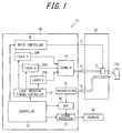
- FIG. 1 is a block diagram illustrating a schematic configuration of an optical scanning endoscope apparatus as an example of the disclosed optical scanning observation apparatus according to Embodiment 1.
- FIG. 1 shows an optical scanning endoscope apparatus 10, which includes a scope 20, a control device body 30, and a display 40.
- the control device body 30 includes: a controller 31 for controlling throughout the optical scanning endoscope apparatus 10; a light emission timing controller 32; lasers 33R, 33G, 33B; a coupler 34; a drive controller 38; a photodetector 35 (optical detector); an analog-digital converter (ADC) 36; and a signal processor 37.
- the emission timing controller 32 controls, based on the control signal from the controller 31, light emission timings of the lasers 33R, 33G, 33B each emitting red (R), green (G), and blue (B) laser lights, respectively.
- the light emission timings are controlled such that the ratio of number of light emissions among the respective light colors is obtained as a set value.
- the value of the ratio of number of light emissions among the respective light colors may be set at an optional timing by a user through input unit (not shown) or set in advance at the time of shipment of the optical scanning endoscope apparatus 10, and stored in a memory (not shown) readable and writable by the controller 31.
- the light emission timings are set such that lights in the different colors may each be emitted at every fixed time interval (light emission cycle T E ) in the light emission sequence (for example, in the order of R, G, B, G) determined based on the set value of the ratio of number of light emissions among the different light colors (for example, 1:2:1 in the order of R, G, B).
- the lasers 33R, 33G, 33B constitute a light source for selectively emitting a plurality of lights of different colors (three colors of R, G, and B in Embodiment 1).
- "selectively emitting a plurality of lights of different colors” specifically refers to emitting light of any one of the colors selected by the light emission timing controller 32 at a timing selected by the light emission timing controller 32.
- Exemplary lasers that can be used as the lasers 33R, 33G, 33B may include, for example, a diode-pump solid state (DPSS) laser and a laser diode.
- DPSS diode-pump solid state
- the "light emission cycle T E" refers to the emission cycle of light sequentially emitted from the light source, rather than the light emission cycle of each of the lasers 33R, 33G, 33B constituting the light source.
- Laser lights emitted from the lasers 33R, 33G, 33B travel through optical paths coaxially combined by the coupler 34, and are made incident, as illumination light, onto an illumination optical fiber 11 (fiber) as a single mode fiber.
- the coupler 34 may be formed using, for example, a dichroic prism.
- the lasers 33R, 33G, 33B and the coupler 34 may be stored in a separate casing different from the control body 30, the separate casing being connected to the control device body 30 via a signal line.
- the light that has been incident onto the illumination optical fiber 11 from the coupler 34 is guided to the tip part of the scope 20 and irradiated toward an object 100.
- the drive controller 38 of the control device body 30 vibratory drives an actuator 21 of the scope 20, to thereby vibratory drive the tip part of the illumination optical fiber 11.
- the illumination light emitted from the illumination optical fiber 11 is two-dimensionally scanned, for example, in a spiral manner, on the observation surface of the object 100.
- the object 100 irradiated by the illumination light provides reflected light and scattered light, which are received at the tip end of a detection optical fiber bundle 12 formed of multimode fibers and guided to the control device body 30 through the scope 20.
- the photodetector 35 detects, for every light emission cycle T E of the light source, light obtained via the detection optical fiber bundle 12 from the object 100 irradiated with light of any color of R, G, or B, and outputs an analog signal (electric signal) band-limited for the color.
- the ADC 36 converts the analog signal from the photodetector 35 into a digital signal (electric signal), and outputs the signal to the signal processor 37.
- the signal processor 37 sequentially stores, in a memory (not shown), each digital signal which is input from the ADC 36 for every light emission cycle T E and corresponds to each color, in association with the light emission timing and the scanned position. Information on the light emission timing and the scanning position is obtained from the controller 31.
- the controller 31 calculates information on the scanning position on the scanning path, based on such information as the amplitude and phase of a vibration voltage applied by the drive controller 38. Then, after the scan is completed or during the scan, the signal processor 37 subjects each digital signal input from the ADC 36 to necessary image processing such as enhancement processing, ⁇ processing, and interpolation processing, to thereby generate an image signal, and displays an image of the object 100 on the display 40.
- FIG. 2 is an overview schematically illustrating the scope 20.
- the scope 20 includes an operation portion 22 and an insertion portion 23.
- the illumination optical fiber 11, the detection optical fiber bundle 12, and a wiring cable 13 from the control device body 30 are each connected to the operation portion 22.
- the illumination optical fiber 11, the detection optical fiber bundle 12, and the wiring cable 13 pass through inside the insertion portion 23, and extend to the tip part 24 (enclosed by the dashed line of FIG. 2 ) of the insertion portion 23.
- FIG. 3 is an enlarged sectional view of the tip part 24 of the insertion portion 23 of the scope 20 of FIG. 2 .
- the tip part 24 of the insertion portion 23 of the scope 20 is configured by including: the actuator 21; a projection lenses 25a, 25b (optical system); the illumination optical fiber 11 passing through the center part; and the detection optical fiber bundle 12 passing through the circumferential part.
- the actuator 21 vibratory drives a tip part 11c of the illumination optical fiber 11.
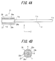
- the actuator 21 is configured by including: an actuator tube 27 fixed inside the insertion portion 23 of the scope 20 through an attachment ring 26; and a fiber holding member 29 and piezoelectric elements 28a to 28d (see FIGS. 4A and 4B ) disposed inside the actuator tube 27.
- the illumination optical fiber 11, which is supported by the fiber holding member 29, has an oscillation part 11b oscillatably supported, the oscillation part 11b being defined between an fixed end 11 a supported by the fiber holding member 29 and the tip part 11c.
- the detection optical fiber bundle 12 is disposed so as to pass through the circumferential part of the insertion portion 23 to extend to the tip end of the tip part 24. Further, the detection optical fiber bundle 12 includes a detection lens, which is not shown, at the tip part of each fiber.
- the projection lenses 25a, 25b and the detection lens are disposed at an extreme tip of the tip part 24 of the insertion portion 23 of the scope 20.
- the projection lenses 25a, 25b are configured such that laser light emitted from the tip part 11c of the illumination optical fiber 11 is irradiated on the object 100 so as to be substantially converged thereon.
- the detection lens is disposed to take in the laser light that has been reflected, scattered, or refracted by the object 100 (light that has interacted with the object 100) after being converged on the object 100, so as to converge and couple the laser light to the detection optical fiber bundle 12 disposed behind the detection lens.
- one projection lens or a plurality of other lenses may constitute the projection lens system, without being limited to the two-lens configuration.
- FIG. 4A illustrates a vibratory driving mechanism of the actuator 21 of the optical scanning endoscope apparatus 10 and the oscillation part 11b of the illumination optical fiber 11, and FIG. 4B is a sectional view taken along the line A-A of FIG. 4A .
- the illumination optical fiber 11 penetrates the center of the fiber holding member 29 in a prism shape, and is fixedly held by the fiber holding member 29.
- the fiber holding member 29 has four side faces each facing the ⁇ Y directions and the ⁇ X directions, respectively, of which two side faces of the fiber holding member 29 facing the ⁇ Y directions have a pair of the Y-direction driving piezoelectric elements 28a, 28c fixed thereon, and two side faces of the fiber holding member 29 facing the ⁇ X directions have a pair of the X-direction driving piezoelectric elements 28b, 28d fixed thereon.
- the piezoelectric elements 28a to 28d are each connected with the wiring cable 13 from the drive controller 38 of the control device body 30, and driven by voltage applied by the drive controller 38.
- Voltages to be applied between the X-direction piezoelectric elements 28b and 28b are constantly inverted with plus and minus but equal to each other in magnitude.
- voltages to be applied between the Y-direction piezoelectric elements 28a and 28c are constantly inverted with plus and minus but equal to each other in magnitude.
- the piezoelectric elements 28a, 28d disposed as being opposite to each other across the fiber holding member 29 one is extended while the other is contracted in an alternating manner to deflect the fiber holding optical fiber 29, which may be repeated to cause vibration in the X direction. Vibration in the Y direction is similarly caused.
- the drive controller 38 applies vibration voltages of the same frequency or applies vibration voltages of different frequencies to the X-direction driving piezoelectric elements 28b, 28d and the Y-direction driving piezoelectric elements 28a, 28c, to thereby vibratory drive the piezoelectric elements 28a to 28d.
- the oscillation part 11b of the illumination optical fiber 11 of FIG. 3 or 4 is vibrated so as to deflect the tip part 11c, and thus, laser light emitted from the tip part 11c is sequentially scanned (for example, in a spiral manner) on the surface of the object 100.
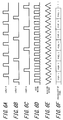
- FIG. 5 is for illustrating an example of the light emission timing of the light source, in which the time sequence is from left to right of the drawing.
- the ratio of number of light emissions among the lights ofR, G, B is defined as 1:2:1, and lights are emitted in the order of R, G, B, G.
- the light emission timing controller 32 controls, in accordance with the control signal from the controller 31, the light emission timings of the lasers 33R, 33G, 33B in the order of R, G, B, G for every light emission cycle T E .
- the light emission timing of the lasers 33R, 33G, 33B at this time are shown in FIGS. 5A to 5C , the output of the coupler 34 is shown in FIG. 5D , and the output of the photodetector 35 is shown in FIG. 5E .
- the signal processor 37 generates image signals, as illustrated in FIG. 5F , based on electric signals for two colors (of R and G, or B and G) sequentially input from the photodetector 35 via the ADC 36, and outputs the signal to the display 40.
- absent color for each pixel may desirably be interpolated with the aid of neighboring pixels.
- electric signals each associated with R and G, respectively are input to a pixel 5 of FIG. 5F , and thus, the absent color B is interpolated based on the neighboring pixels by a publicly-known method.
- image signal components of three colors of RGB can be incorporated per one pixel, which improves the image definition.
- the "neighboring pixels” herein refer to neighboring pixels along the scanning trajectory of the tip part 11c of the illumination optical fiber 11, or neighboring pixels to be found when generating image signals to be output to the display 40.
- the ratio of number of light emissions of G may be set higher as compared to the rest of the colors as in this example, to thereby obtain sufficiently excellent image resolution (definition) while reducing current consumption.
- the light emission cycle T E is 1/2 of a cycle (pixel cycle) T P at which electric signals for one pixel are input.
- the light emission cycle T E ' is 1/3 of the pixel cycle T P '. Accordingly, suppose that the pixel cycles T P , T P ' are the same, the light emission cycle T E in the example of FIG. 5 becomes longer than the light emission cycle T E ' in the conventional example of FIG. 10 , which allows the signal band width to be narrowed in the photodetector 35, to thereby reduce noise resulting from superposition of signals of different colors potentially caused by ringing phenomenon. On the other hand, suppose the light emission cycles T E , T E ' are the same, the pixel cycle TP in the example of FIG. 5 becomes shorter than the pixel cycle TP' in the conventional example of FIG. 10 , which can improve image resolution.
- the ratio of number of light emissions of R may desirably be increased to be higher as compared to the other colors (G, B) as in another example of FIG. 6 because the color R highly contributes to image brightness.
- the ratio of number of light emissions of R, G, B is defined as 2:1:1, and lights are emitted in the order of G, R, B, R.
- the ratio of number of light emissions of B may desirably be increased to be higher as compared to the other colors (R, G) because the color B highly contributes to brightness of the image.
- R, G the other colors
- any color may be selected to be increased in light emission ratio thereof.
- a highly contrasted color in the captured image or a color having frequency components across a wide bandwidth may be selected, or the color may be determined depending on the combination of the aforementioned image qualities.
- the ratio of number of light emissions of each color may desirably be determined in such a manner that a color with the highest contribution to image brightness may have a higher ratio of number of light emissions than the rest of the colors.
- Embodiment 1 current consumption can be reduced while suppressing degradation in image resolution.
- FIG. 7 is a block diagram illustrating a schematic configuration of an optical scanning endoscope apparatus as an example of the disclosed optical scanning observation apparatus according to Embodiment 2.
- Embodiment 2 is different from Embodiment 1 in that the control device body 30 further includes an object color detector 70, and thus detailed description of the rest of the configuration is omitted.
- the ratio of number of light emissions of each color of light from the light source is set by the user through an input unit at an optional timing or may be set in advance at the time of shipment of the optical scanning endoscope apparatus, while in Embodiment 2, the ratio of number of light emissions is automatically optimized by the object color detector 70 depending on the object. This configuration saves user's trouble of resetting the ratio of number of light emissions every time observing a different object, which thus improves user convenience as compared with Embodiment 1.
- the object color detector 70 is connected to the signal processor 37 and to the controller.
- the object color detector 70 extracts, based on an image signal generated by the signal processor 37, a color with high contribution to image brightness (luminance), determines the ratio of number of light emissions of each color such that the extracted color has the higher ratio of number of light emissions than the rest of the colors, and notifies the controller 31 of the ratio of number of light emissions thus determined.
- FIG. 8 is a flow chart illustrating the processing in the object color detector 70.
- the emission timing of FIG. 5 is set as the initial setting, in which the ratio of number of light emissions among the lights of R, G, B is defined as 1:2:1.
- the initial setting is set in advance, for example, through the user input or through an input at the time of shipment of the optical scanning endoscope apparatus 10.
- Step S1 When image signals of an arbitrary image is input from the signal processor 37 (Step S1, Yes), the object color detector 70 calculates an average level of the image signal values for the respective colors of R, G, B (Step S2). Steps S1 to S2 may process each image signal involved throughout the one image, or may process only some image signals involved in a part (for example, the region of interest, such as the central region) of the one image.
- the object color detector 70 multiplies the average level of the image signal values of the respective colors calculated in Step S2 with a coefficient related to luminance of each color (Step S3).
- the coefficient is stored in a memory (not shown) in advance, an example of which is available as a coefficient generally used for calculating the luminance signal of a display (coefficient of 0.3 for R, 0.59 for G, and 0.11 for B).
- the object color detector 70 compares the product values obtained in Step S3 (Step S4), extracts a color corresponding to the maximum value as a color having highest contribution to brightness (luminance) of the image (Steps S5 to S7), and sets the ratio of number of light emissions of the color two times higher than the rest of the colors (Steps S8 to S10).
- the ratio of number of light emissions set by the object color detector 70 is conveyed to the controller, which updates the set value of the ratio of number of light emissions held in the controller 31.
- the light emission timing controller 32 controls, in response to a control signal from the controller 31, the ratio of number of light emissions for each color of light from the light source, according to the ratio of number of light emissions determined by the object color detector 70.
- the object color detector 70 has extracted G as the color having highest contribution to image luminance (Step S5, Yes)
- the ratio of number of light emissions among R, G, B is maintained as 1:2:1 (Step S8), and the light emission timing controller 32 continues to control the light source in line with the light emission timing of FIG. 5.
- the object color detector 70 has extracted R as the color having highest contribution to image luminance (Step S6, Yes)
- the ratio of number of light emissions among R, G, B is changed to 2:1:1, and the light emission timing controller 32 then controls the light source in line with the light emission timing of FIG. 6.
- the ratio of number of light emissions is automatically optimized, saving user's trouble of resetting the ratio of number of light emissions every time observing a different object, which thus improves user convenience.
- Step S8 may be performed at an optional timing during the observation (scan) of the object; for example, the process may be performed only at the start of observation or may be performed periodically during observation.
- Step S1 may wait until the user inputs a process start instruction via the input unit (not shown). In this case, when the user inputs the process start instruction in Step S1, the object color detector 70 performs Step S2 and the steps that follow Step S2.
- an optional light emission timing may be set, such as the light emission timing as illustrated in the example of FIG. 10 where the ratio of number of light emissions among R, G, B is 1:1:1.
- the ratio of number of light emissions of each color may be set to an optional value so that a color of highest contribution to image brightness has the ratio of number of light emissions higher than the rest of the colors.
- the ratio of number of light emissions of each color may be set (for example, to 3:2:1) so as to be proportional to the product value of each color calculated in Step S3, or the product values of the respective values may be aligned in the same descending order as the ratio of number of light emissions of each color.
- any color may be selected to be increased in light emission ratio thereof.
- a highly contrasted color in the captured image or a color having frequency components across a wide bandwidth may be selected, or the color may be determined depending on the combination of the aforementioned image qualities.
- the optical scanning endoscope apparatus 10 may include any light source without being limited to the configuration which includes the lasers 33R, 33G, 33B, as long as it selectively emits a plurality of lights of different colors.
- An example of such light source may be configured to diffract a plurality of lights of different colors emitted from a white light source and selectively emit the diffracted lights.
- the actuator 21 of the illumination optical fiber 11 is not limited to the one using a piezoelectric elements, and may use, for example, a permanent magnet fixed to the illumination optical fiber 11 and a deflecting magnetic field generating coil (electromagnetic coil) for driving the permanent magnet.
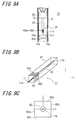
- FIGS. 9A and 9B a modified example of the actuator 21 is explained with reference to FIGS. 9A and 9B.
- FIG. 9A is a sectional view of the tip part 24 of the scope 20
- FIG. 9B is an enlarged perspective view of the actuator 21 of FIG. 9A
- FIG. 9C is a sectional view of a portion including deflecting magnetic field generating coils 62a to 62d and a permanent magnet 63 of FIG. 9B taken along a plane perpendicular to the axis of the optical fiber 11.
- the oscillation part 11b of the illumination optical fiber 11 is coupled, in part, with the permanent magnet 63 which is magnetized in the axial direction of the illumination optical fiber 11 and has a through hole, with the illumination optical fiber 11 penetrating the through hole. Further, an angular tube 61 fixed at one end thereof to the attachment ring 26 is disposed so as to surround the oscillation part 11b, and the angular tube 61 has deflecting magnetic field generating coils 62a to 62d of flat package type each disposed on respective side faces thereof in a region facing one of the magnetic poles of the permanent magnet 63.
- the pair of the deflecting magnetic field generating coils 62a and 62c in the Y direction and the pair of the deflecting magnetic field generating coils 62b and 62d in the X direction are disposed on faces opposing to each other of the angular tube 61, in which a line connecting the center of the deflecting magnetic field generating coil 62a and the center of the deflecting magnetic field generating coil 62c and a line connecting the center of deflecting magnetic field generating coil 62b and the center of the deflecting magnetic field generating coil 62d intersect with each other at right angles near the central axis of the angular tube 61 where the illumination optical fiber 11 is disposed when stationary.
- the coils are connected, via the wiring cable 13, to the actuator 38 of the control device body 30 and driven by a drive current from the drive controller 38.
- the disclosed optical scanning observation apparatus may also be applied to other optical scanning observation apparatus such as an optical scanning microscope, without being limited to the optical scanning endoscope apparatus.
Landscapes
- Physics & Mathematics (AREA)
- Optics & Photonics (AREA)
- Health & Medical Sciences (AREA)
- Life Sciences & Earth Sciences (AREA)
- General Physics & Mathematics (AREA)
- Engineering & Computer Science (AREA)
- Surgery (AREA)
- Astronomy & Astrophysics (AREA)
- Multimedia (AREA)
- Biomedical Technology (AREA)
- Animal Behavior & Ethology (AREA)
- Pathology (AREA)
- Nuclear Medicine, Radiotherapy & Molecular Imaging (AREA)
- Heart & Thoracic Surgery (AREA)
- Medical Informatics (AREA)
- Molecular Biology (AREA)
- Radiology & Medical Imaging (AREA)
- General Health & Medical Sciences (AREA)
- Public Health (AREA)
- Veterinary Medicine (AREA)
- Biophysics (AREA)
- Signal Processing (AREA)
- Endoscopes (AREA)
- Instruments For Viewing The Inside Of Hollow Bodies (AREA)
Abstract
Description
- The present disclosure relates to an optical scanning observation apparatus which optically scans an object through vibration of an optical fiber.
- There has been hitherto known a medical probe for observing an object using pulse lights of a plurality of different wavelengths irradiated from a light source, the probe having: a light guide unit guiding the pulse light incident from the light source to emit the light to the object; and an optical delay unit for giving, with respect to reflected pulse light from the object irradiated with the emitted pulse light, a predetermined delay time that is different for each wavelength, the probe outputting the pulse light which is given the delay time to a predetermined photodetector (see, for example, Patent Literature 1). This configuration is considered to allow for reducing to one the number of the optical detectors.
- Another conceivable technique that allows for reducing to one the number of optical detectors may involve sequentially switching lasers of red, green, blue along with a sampling rate as illustrated in
FIG. 10 for example, so as to sequentially irradiate pulse light of each color onto the object. - PTL 1:
JP201042128A - In general, however, a color having small contribution to image luminance is assumed to have less influence on image resolution (definition) even if the light emission thereof is less frequent than those of the other colors. Thus, the current consumption for light emission can be considered to have still some room for reduction in the example of
FIG. 10 , where red, green, and blue lights are emitted at the equal ratio. - Therefore, it would be helpful to provide an optical scanning observation apparatus allowing for reducing current consumption while suppressing degradation in image resolution.
- An optical scanning observation apparatus to be provided includes:
- a light source selectively emitting a plurality of lights of different colors;
- a light emission timing controller controlling light emission timing, based on a predetermined ratio of number of light emissions of each color of light emitted from the light source;
- a fiber guiding light from the light source and emitting the light from a tip part of the fiber, the tip part being oscillatably supported;
- an actuator vibratory driving the tip part of the fiber;
- an optical system for irradiating light emitted from the fiber toward an obj ect;
- an optical detector detecting light obtained from the object via the irradiating of the light and converting the light obtained from the object into an electric signal; and
- a signal processor generating an image signal, based on the electric signal from the optical detector.
- The light emission timing controller may preferably define the ratio of number of light emissions of a color having high contribution to image quality, to be higher than the ratio of number of light emissions of the rest of the colors.
- Here, the image quality may include image brightness or contrast or bandwidth, or any combination thereof.
- The optical scanning observation apparatus may further include an object color detector for extracting, based on the image signal generated by the image generator, a color having high contribution to image brightness of an image to be generated by the image signal,
in which the light emission timing controller may control, based on the output from the object color detector, the ratio of number of light emissions for each color of light from the light source. - The disclosed optical scanning observation apparatus thus provided can reduce current consumption while suppressing degradation in image resolution.
- In the accompanying drawings:
-
FIG. 1 is a block diagram illustrating a schematic configuration of an optical scanning endoscope apparatus as an example of the disclosed optical scanning observation apparatus according toEmbodiment 1; -
FIG. 2 is an overview schematically illustrating the scope ofFIG. 1 ; -
FIG. 3 is a sectional view of the tip part of the scope ofFIG. 2 ; -
FIGS. 4A and 4B each illustrate the actuator and the oscillation part of the illumination optical fiber ofFIG. 3 , in whichFIG. 4A is a side view thereof, andFIG. 4B is a sectional view taken along the line A-A ofFIG. 4A ; -
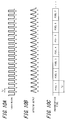
FIG. 5 is for illustrating an example of the light emission timing of the light source; -
FIG. 6 is for illustrating another example of the light emission timing of the light source; -
FIG. 7 is a block diagram illustrating a schematic configuration of an optical scanning endoscope apparatus as an example of the disclosed optical scanning observation apparatus according toEmbodiment 2; -
FIG. 8 is a flow chart illustrating the processing in the object color detector ofFIG. 7 ; -
FIGS. 9A to 9C are diagrams for illustrating a modified example of the actuator ofFIG. 4 , in whichFIG. 9A is a sectional view of the tip part of the scope,FIG. 9B is an enlarged perspective view of the actuator ofFIG. 9A, and FIG. 9C is a sectional view of a portion including the deflecting magnetic field generating coils and the permanent magnet ofFIG. 9B taken along a plane perpendicular to the axis of the optical fiber; and -
FIG. 10 is a view for illustrating an example of conventional light emission timing. - The following describes Embodiments disclosed herein, with reference to the drawings.
-
Embodiment 1 of the disclosed optical scanning observation apparatus is described with reference toFIGS. 1 to 6 .FIG. 1 is a block diagram illustrating a schematic configuration of an optical scanning endoscope apparatus as an example of the disclosed optical scanning observation apparatus according toEmbodiment 1.FIG. 1 shows an opticalscanning endoscope apparatus 10, which includes ascope 20, acontrol device body 30, and adisplay 40. - First, a configuration of the
control device body 30 is described. Thecontrol device body 30 includes: acontroller 31 for controlling throughout the opticalscanning endoscope apparatus 10; a lightemission timing controller 32;lasers coupler 34; adrive controller 38; a photodetector 35 (optical detector); an analog-digital converter (ADC) 36; and asignal processor 37. - The
emission timing controller 32 controls, based on the control signal from thecontroller 31, light emission timings of thelasers Embodiment 1, the value of the ratio of number of light emissions among the respective light colors may be set at an optional timing by a user through input unit (not shown) or set in advance at the time of shipment of the opticalscanning endoscope apparatus 10, and stored in a memory (not shown) readable and writable by thecontroller 31. The light emission timings are set such that lights in the different colors may each be emitted at every fixed time interval (light emission cycle TE) in the light emission sequence (for example, in the order of R, G, B, G) determined based on the set value of the ratio of number of light emissions among the different light colors (for example, 1:2:1 in the order of R, G, B). - The
lasers emission timing controller 32 at a timing selected by the lightemission timing controller 32. Exemplary lasers that can be used as thelasers - Here, in the disclosure, the "light emission cycle TE" refers to the emission cycle of light sequentially emitted from the light source, rather than the light emission cycle of each of the
lasers - Laser lights emitted from the
lasers coupler 34, and are made incident, as illumination light, onto an illumination optical fiber 11 (fiber) as a single mode fiber. Thecoupler 34 may be formed using, for example, a dichroic prism. - The
lasers coupler 34 may be stored in a separate casing different from thecontrol body 30, the separate casing being connected to thecontrol device body 30 via a signal line. - The light that has been incident onto the illumination
optical fiber 11 from thecoupler 34 is guided to the tip part of thescope 20 and irradiated toward anobject 100. At this time, thedrive controller 38 of thecontrol device body 30 vibratory drives anactuator 21 of thescope 20, to thereby vibratory drive the tip part of the illuminationoptical fiber 11. In this manner, the illumination light emitted from the illuminationoptical fiber 11 is two-dimensionally scanned, for example, in a spiral manner, on the observation surface of theobject 100. Theobject 100 irradiated by the illumination light provides reflected light and scattered light, which are received at the tip end of a detectionoptical fiber bundle 12 formed of multimode fibers and guided to thecontrol device body 30 through thescope 20. - The
photodetector 35 detects, for every light emission cycle TE of the light source, light obtained via the detectionoptical fiber bundle 12 from theobject 100 irradiated with light of any color of R, G, or B, and outputs an analog signal (electric signal) band-limited for the color. - The
ADC 36 converts the analog signal from thephotodetector 35 into a digital signal (electric signal), and outputs the signal to thesignal processor 37. - The
signal processor 37 sequentially stores, in a memory (not shown), each digital signal which is input from theADC 36 for every light emission cycle TE and corresponds to each color, in association with the light emission timing and the scanned position. Information on the light emission timing and the scanning position is obtained from thecontroller 31. Thecontroller 31 calculates information on the scanning position on the scanning path, based on such information as the amplitude and phase of a vibration voltage applied by thedrive controller 38. Then, after the scan is completed or during the scan, thesignal processor 37 subjects each digital signal input from theADC 36 to necessary image processing such as enhancement processing, γ processing, and interpolation processing, to thereby generate an image signal, and displays an image of theobject 100 on thedisplay 40. - Next, a configuration of the
scope 20 is described.FIG. 2 is an overview schematically illustrating thescope 20. Thescope 20 includes anoperation portion 22 and aninsertion portion 23. The illuminationoptical fiber 11, the detectionoptical fiber bundle 12, and awiring cable 13 from thecontrol device body 30 are each connected to theoperation portion 22. The illuminationoptical fiber 11, the detectionoptical fiber bundle 12, and thewiring cable 13 pass through inside theinsertion portion 23, and extend to the tip part 24 (enclosed by the dashed line ofFIG. 2 ) of theinsertion portion 23. -
FIG. 3 is an enlarged sectional view of thetip part 24 of theinsertion portion 23 of thescope 20 ofFIG. 2 . Thetip part 24 of theinsertion portion 23 of thescope 20 is configured by including: theactuator 21; aprojection lenses optical fiber 11 passing through the center part; and the detectionoptical fiber bundle 12 passing through the circumferential part. - The
actuator 21 vibratory drives atip part 11c of the illuminationoptical fiber 11. Theactuator 21 is configured by including: anactuator tube 27 fixed inside theinsertion portion 23 of thescope 20 through anattachment ring 26; and afiber holding member 29 andpiezoelectric elements 28a to 28d (seeFIGS. 4A and 4B ) disposed inside theactuator tube 27. The illuminationoptical fiber 11, which is supported by thefiber holding member 29, has anoscillation part 11b oscillatably supported, theoscillation part 11b being defined between anfixed end 11 a supported by thefiber holding member 29 and thetip part 11c. Meanwhile, the detectionoptical fiber bundle 12 is disposed so as to pass through the circumferential part of theinsertion portion 23 to extend to the tip end of thetip part 24. Further, the detectionoptical fiber bundle 12 includes a detection lens, which is not shown, at the tip part of each fiber. - Further, the
projection lenses tip part 24 of theinsertion portion 23 of thescope 20. Theprojection lenses tip part 11c of the illuminationoptical fiber 11 is irradiated on theobject 100 so as to be substantially converged thereon. Further, the detection lens is disposed to take in the laser light that has been reflected, scattered, or refracted by the object 100 (light that has interacted with the object 100) after being converged on theobject 100, so as to converge and couple the laser light to the detectionoptical fiber bundle 12 disposed behind the detection lens. Here, one projection lens or a plurality of other lenses may constitute the projection lens system, without being limited to the two-lens configuration. -
FIG. 4A illustrates a vibratory driving mechanism of theactuator 21 of the opticalscanning endoscope apparatus 10 and theoscillation part 11b of the illuminationoptical fiber 11, andFIG. 4B is a sectional view taken along the line A-A ofFIG. 4A . The illuminationoptical fiber 11 penetrates the center of thefiber holding member 29 in a prism shape, and is fixedly held by thefiber holding member 29. Thefiber holding member 29 has four side faces each facing the ±Y directions and the ±X directions, respectively, of which two side faces of thefiber holding member 29 facing the ±Y directions have a pair of the Y-direction drivingpiezoelectric elements fiber holding member 29 facing the ±X directions have a pair of the X-direction drivingpiezoelectric elements - The
piezoelectric elements 28a to 28d are each connected with thewiring cable 13 from thedrive controller 38 of thecontrol device body 30, and driven by voltage applied by thedrive controller 38. - Voltages to be applied between the X-direction
piezoelectric elements piezoelectric elements piezoelectric elements fiber holding member 29, one is extended while the other is contracted in an alternating manner to deflect the fiber holdingoptical fiber 29, which may be repeated to cause vibration in the X direction. Vibration in the Y direction is similarly caused. - The
drive controller 38 applies vibration voltages of the same frequency or applies vibration voltages of different frequencies to the X-direction drivingpiezoelectric elements piezoelectric elements piezoelectric elements 28a to 28d. When the Y-direction drivingpiezoelectric elements piezoelectric elements oscillation part 11b of the illuminationoptical fiber 11 ofFIG. 3 or4 is vibrated so as to deflect thetip part 11c, and thus, laser light emitted from thetip part 11c is sequentially scanned (for example, in a spiral manner) on the surface of theobject 100. - Next, an operation of the optical
scanning endoscope apparatus 10 is described with reference toFIG. 5 , mainly about the processing in the lightemission timing controller 32 and in thesignal processor 37.FIG. 5 is for illustrating an example of the light emission timing of the light source, in which the time sequence is from left to right of the drawing. In the example ofFIG. 5 , the ratio of number of light emissions among the lights ofR, G, B is defined as 1:2:1, and lights are emitted in the order of R, G, B, G. The lightemission timing controller 32 controls, in accordance with the control signal from thecontroller 31, the light emission timings of thelasers lasers FIGS. 5A to 5C , the output of thecoupler 34 is shown inFIG. 5D , and the output of thephotodetector 35 is shown inFIG. 5E . - The
signal processor 37 generates image signals, as illustrated inFIG. 5F , based on electric signals for two colors (of R and G, or B and G) sequentially input from thephotodetector 35 via theADC 36, and outputs the signal to thedisplay 40. At this time, absent color for each pixel may desirably be interpolated with the aid of neighboring pixels. For example, electric signals each associated with R and G, respectively, are input to apixel 5 ofFIG. 5F , and thus, the absent color B is interpolated based on the neighboring pixels by a publicly-known method. Through such interpolation processing, image signal components of three colors of RGB can be incorporated per one pixel, which improves the image definition. Here, the "neighboring pixels" herein refer to neighboring pixels along the scanning trajectory of thetip part 11c of the illuminationoptical fiber 11, or neighboring pixels to be found when generating image signals to be output to thedisplay 40. - As described above, in the example of the light emission timings of
FIGS. 5 , light is emitted twice per one pixel (number of light emission pulses), which is 2/3 of the three times in the conventional example ofFIG. 10 . This configuration reduces to 2/3 current consumption for laser emission, provided that the pulse width is supposedly the same as that of the conventional example ofFIG. 10 . On the other hand, it is generally known that the color G highly contributes to brightness (luminance) of the image as compared with the other colors (R, B), while the color B less contributes to brightness as compared with the other colors (R, G). Accordingly, in a case where the object includes not so many R and B components in particular, the ratio of number of light emissions of G may be set higher as compared to the rest of the colors as in this example, to thereby obtain sufficiently excellent image resolution (definition) while reducing current consumption. - Further, in the examples of
FIGS. 5 , the light emission cycle TE is 1/2 of a cycle (pixel cycle) TP at which electric signals for one pixel are input. On the other hand, in the conventional example ofFIG. 10 , the light emission cycle TE' is 1/3 of the pixel cycle TP'. Accordingly, suppose that the pixel cycles TP, TP' are the same, the light emission cycle TE in the example ofFIG. 5 becomes longer than the light emission cycle TE' in the conventional example ofFIG. 10 , which allows the signal band width to be narrowed in thephotodetector 35, to thereby reduce noise resulting from superposition of signals of different colors potentially caused by ringing phenomenon. On the other hand, suppose the light emission cycles TE, TE' are the same, the pixel cycle TP in the example ofFIG. 5 becomes shorter than the pixel cycle TP' in the conventional example ofFIG. 10 , which can improve image resolution. - Meanwhile, in a case where the image depicts an object having particularly many R components (such as an image of the inside of a blood vessel), the ratio of number of light emissions of R may desirably be increased to be higher as compared to the other colors (G, B) as in another example of
FIG. 6 because the color R highly contributes to image brightness. In the example ofFIG. 6 , the ratio of number of light emissions of R, G, B is defined as 2:1:1, and lights are emitted in the order of G, R, B, R. With this configuration, sufficiently excellent image resolution can be obtained while reducing current consumption to 2/3 of that in the conventional practice. - Similarly, in a case where the image depicts an object having particularly many B components (such as an image of a part stained with a dye of blue B so as to facilitate recognition of the inflamed side site), the ratio of number of light emissions of B may desirably be increased to be higher as compared to the other colors (R, G) because the color B highly contributes to brightness of the image. Here, without being limited to the aforementioned example which increases the light emission ratio of a color having high contribution to brightness, any color may be selected to be increased in light emission ratio thereof. For example, a highly contrasted color in the captured image or a color having frequency components across a wide bandwidth may be selected, or the color may be determined depending on the combination of the aforementioned image qualities.
- As described above, in view of reducing the current consumption while suppressing degradation in image resolution, the ratio of number of light emissions of each color may desirably be determined in such a manner that a color with the highest contribution to image brightness may have a higher ratio of number of light emissions than the rest of the colors.
- According to
Embodiment 1, current consumption can be reduced while suppressing degradation in image resolution. -
Embodiment 2 of the disclosed optical scanning observation apparatus is described with reference toFIGS. 7 and8 .FIG. 7 is a block diagram illustrating a schematic configuration of an optical scanning endoscope apparatus as an example of the disclosed optical scanning observation apparatus according toEmbodiment 2.Embodiment 2 is different fromEmbodiment 1 in that thecontrol device body 30 further includes anobject color detector 70, and thus detailed description of the rest of the configuration is omitted. - In
Embodiment 1, the ratio of number of light emissions of each color of light from the light source is set by the user through an input unit at an optional timing or may be set in advance at the time of shipment of the optical scanning endoscope apparatus, while inEmbodiment 2, the ratio of number of light emissions is automatically optimized by theobject color detector 70 depending on the object. This configuration saves user's trouble of resetting the ratio of number of light emissions every time observing a different object, which thus improves user convenience as compared withEmbodiment 1. - As illustrated in
FIG. 7 , theobject color detector 70 is connected to thesignal processor 37 and to the controller. Theobject color detector 70 extracts, based on an image signal generated by thesignal processor 37, a color with high contribution to image brightness (luminance), determines the ratio of number of light emissions of each color such that the extracted color has the higher ratio of number of light emissions than the rest of the colors, and notifies thecontroller 31 of the ratio of number of light emissions thus determined. - Next, an operation of the optical
scanning endoscope apparatus 10 is described with reference toFIG. 8 , mainly about the processing in the lightemission timing controller 32, in thesignal processor 37, and in theobject color detector 70.FIG. 8 is a flow chart illustrating the processing in theobject color detector 70. InEmbodiment 2, the emission timing ofFIG. 5 is set as the initial setting, in which the ratio of number of light emissions among the lights of R, G, B is defined as 1:2:1. The initial setting is set in advance, for example, through the user input or through an input at the time of shipment of the opticalscanning endoscope apparatus 10. - When image signals of an arbitrary image is input from the signal processor 37 (Step S1, Yes), the
object color detector 70 calculates an average level of the image signal values for the respective colors of R, G, B (Step S2). Steps S1 to S2 may process each image signal involved throughout the one image, or may process only some image signals involved in a part (for example, the region of interest, such as the central region) of the one image. - Next, the
object color detector 70 multiplies the average level of the image signal values of the respective colors calculated in Step S2 with a coefficient related to luminance of each color (Step S3). The coefficient is stored in a memory (not shown) in advance, an example of which is available as a coefficient generally used for calculating the luminance signal of a display (coefficient of 0.3 for R, 0.59 for G, and 0.11 for B). - According to
Embodiment 2, the ratio of number of light emissions is automatically optimized, saving user's trouble of resetting the ratio of number of light emissions every time observing a different object, which thus improves user convenience. - The process of Step S8 may be performed at an optional timing during the observation (scan) of the object; for example, the process may be performed only at the start of observation or may be performed periodically during observation. When the process of
FIG. 8 is performed during observation, Step S1 may wait until the user inputs a process start instruction via the input unit (not shown). In this case, when the user inputs the process start instruction in Step S1, theobject color detector 70 performs Step S2 and the steps that follow Step S2. - As the initial setting of the process of
FIG. 8 , an optional light emission timing may be set, such as the light emission timing as illustrated in the example ofFIG. 10 where the ratio of number of light emissions among R, G, B is 1:1:1. - In Steps S5 to S8 of
FIG. 8 , the ratio of number of light emissions of each color may be set to an optional value so that a color of highest contribution to image brightness has the ratio of number of light emissions higher than the rest of the colors. For example, the ratio of number of light emissions of each color may be set (for example, to 3:2:1) so as to be proportional to the product value of each color calculated in Step S3, or the product values of the respective values may be aligned in the same descending order as the ratio of number of light emissions of each color. Further, as inEmbodiment 1, without being limited to the aforementioned example which increases the light emission ratio of a color having high contribution to brightness, any color may be selected to be increased in light emission ratio thereof. For example, a highly contrasted color in the captured image or a color having frequency components across a wide bandwidth may be selected, or the color may be determined depending on the combination of the aforementioned image qualities. - In
Embodiments scanning endoscope apparatus 10 may include any light source without being limited to the configuration which includes thelasers - Further, in
Embodiments actuator 21 of the illuminationoptical fiber 11 is not limited to the one using a piezoelectric elements, and may use, for example, a permanent magnet fixed to the illuminationoptical fiber 11 and a deflecting magnetic field generating coil (electromagnetic coil) for driving the permanent magnet. In below, a modified example of theactuator 21 is explained with reference toFIGS. 9A and 9B. FIG. 9A is a sectional view of thetip part 24 of thescope 20,FIG. 9B is an enlarged perspective view of theactuator 21 ofFIG. 9A, and FIG. 9C is a sectional view of a portion including deflecting magneticfield generating coils 62a to 62d and apermanent magnet 63 ofFIG. 9B taken along a plane perpendicular to the axis of theoptical fiber 11. - The
oscillation part 11b of the illuminationoptical fiber 11 is coupled, in part, with thepermanent magnet 63 which is magnetized in the axial direction of the illuminationoptical fiber 11 and has a through hole, with the illuminationoptical fiber 11 penetrating the through hole. Further, anangular tube 61 fixed at one end thereof to theattachment ring 26 is disposed so as to surround theoscillation part 11b, and theangular tube 61 has deflecting magneticfield generating coils 62a to 62d of flat package type each disposed on respective side faces thereof in a region facing one of the magnetic poles of thepermanent magnet 63. - The pair of the deflecting magnetic
field generating coils field generating coils angular tube 61, in which a line connecting the center of the deflecting magneticfield generating coil 62a and the center of the deflecting magneticfield generating coil 62c and a line connecting the center of deflecting magneticfield generating coil 62b and the center of the deflecting magneticfield generating coil 62d intersect with each other at right angles near the central axis of theangular tube 61 where the illuminationoptical fiber 11 is disposed when stationary. The coils are connected, via thewiring cable 13, to theactuator 38 of thecontrol device body 30 and driven by a drive current from thedrive controller 38. - The disclosed optical scanning observation apparatus may also be applied to other optical scanning observation apparatus such as an optical scanning microscope, without being limited to the optical scanning endoscope apparatus.
-
- 10
- optical scanning endoscope apparatus
- 11
- illumination optical fiber
- 11a
- fixed end
- 11b
- oscillation part
- 11c
- tip part
- 12
- detection optical fiber bundle
- 13
- wiring cable
- 20
- scope
- 21
- actuator
- 22
- operation portion
- 23
- insertion portion
- 24
- tip part
- 25a, 25b
- projection lens
- 26
- attachment ring
- 27
- actuator tube
- 28a to 28d
- piezoelectric element
- 29
- fiber holding member
- 30
- control device body
- 31
- controller
- 32
- light emission timing controller
- 33R, 33G, 33B
- laser
- 34
- coupler
- 35
- photodetector
- 36
- ADC
- 37
- signal processor
- 38
- drive controller
- 40
- display
- 61
- angular tube
- 62a to 62d
- deflecting magnetic field generating coil
- 63
- permanent magnet
- 70
- object color detector
- 100
- object
Claims (4)
- An optical scanning observation apparatus, comprising:a light source selectively emitting a plurality of lights of different colors;a light emission timing controller controlling light emission timing, based on a predetermined ratio of number of light emissions of each color of light emitted from the light source;a fiber guiding light from the light source and emitting the light from a tip part of the fiber, the tip part being oscillatably supported;an actuator vibratory driving the tip part of the fiber;an optical system for irradiating light emitted from the fiber toward an object;an optical detector detecting light obtained from the object via the irradiating of the light and converting the light obtained from the object into an electric signal; anda signal processor generating an image signal, based on the electric signal from the optical detector.
- The optical scanning observation apparatus according to claim 1, wherein the light emission timing controller defines the ratio of number of light emissions of a color having high contribution to image quality, to be higher than the ratio of number of light emissions of the rest of the colors.
- The optical scanning observation apparatus according to claim 2, wherein the image quality according to claim 2 comprises image brightness or contrast or bandwidth, or any combination thereof.
- The optical scanning observation apparatus according to claim 1 or 2, further comprising an object color detector extracting, based on the image signal generated by the signal processor, a color having high contribution to image brightness of an image to be generated by the image signal,
the light emission timing controller controlling, based on the output from the object color detector, the ratio of number of light emissions for each color of light from the light source.
Applications Claiming Priority (2)
| Application Number | Priority Date | Filing Date | Title |
|---|---|---|---|
| JP2013266932A JP6270465B2 (en) | 2013-12-25 | 2013-12-25 | Optical scanning observation device |
| PCT/JP2014/006461 WO2015098114A1 (en) | 2013-12-25 | 2014-12-25 | Optical-scanning-type observation device |
Publications (2)
| Publication Number | Publication Date |
|---|---|
| EP3087900A1 true EP3087900A1 (en) | 2016-11-02 |
| EP3087900A4 EP3087900A4 (en) | 2017-11-15 |
Family
ID=53478010
Family Applications (1)
| Application Number | Title | Priority Date | Filing Date |
|---|---|---|---|
| EP14875488.0A Withdrawn EP3087900A4 (en) | 2013-12-25 | 2014-12-25 | Optical-scanning-type observation device |
Country Status (5)
| Country | Link |
|---|---|
| US (1) | US10151914B2 (en) |
| EP (1) | EP3087900A4 (en) |
| JP (1) | JP6270465B2 (en) |
| CN (1) | CN105848553B (en) |
| WO (1) | WO2015098114A1 (en) |
Families Citing this family (11)
| Publication number | Priority date | Publication date | Assignee | Title |
|---|---|---|---|---|
| WO2014018936A2 (en) * | 2012-07-26 | 2014-01-30 | Olive Medical Corporation | Continuous video in a light deficient environment |
| CN105407789B (en) * | 2013-08-01 | 2017-07-14 | 奥林巴斯株式会社 | The method of work of endoscopic system, endoscopic system |
| EP3119265B1 (en) | 2014-03-21 | 2019-09-11 | DePuy Synthes Products, Inc. | Card edge connector for an imaging sensor |
| JP6206691B2 (en) * | 2014-03-31 | 2017-10-04 | 富士フイルム株式会社 | Endoscope system and operating method thereof |
| WO2017109814A1 (en) * | 2015-12-21 | 2017-06-29 | オリンパス株式会社 | Light scanning observation device |
| DE112016006140T5 (en) * | 2016-02-29 | 2018-09-13 | Olympus Corporation | Imaging / projection device with optical scanning and endoscope system |
| WO2017195256A1 (en) * | 2016-05-09 | 2017-11-16 | オリンパス株式会社 | Optical scanning type observation device and optical scanning type observation method |
| CN107569205B (en) * | 2017-09-21 | 2019-08-16 | 华中科技大学鄂州工业技术研究院 | an endoscope |
| JP6942622B2 (en) * | 2017-12-19 | 2021-09-29 | 株式会社日立製作所 | Optical scanning device, catheter device, and distance measuring device |
| US11143855B2 (en) * | 2018-07-17 | 2021-10-12 | Huron Technologies International Inc. | Scanning microscope using pulsed illumination and MSIA |
| JP7784429B2 (en) * | 2021-06-29 | 2025-12-11 | 浜松ホトニクス株式会社 | Optical image processing method, machine learning method, trained model, machine learning preprocessing method, optical image processing module, optical image processing program, and optical image processing system |
Family Cites Families (11)
| Publication number | Priority date | Publication date | Assignee | Title |
|---|---|---|---|---|
| JPH0210308A (en) * | 1988-06-29 | 1990-01-16 | Toshiba Corp | Endoscope device |
| JP2002122794A (en) * | 2000-10-13 | 2002-04-26 | Asahi Optical Co Ltd | Light source for electronic endoscope |
| JP2006217317A (en) * | 2005-02-04 | 2006-08-17 | Pentax Corp | CCD damage prevention system |
| US20090091614A1 (en) * | 2005-05-13 | 2009-04-09 | Olympus Medical Systems Corp. | Biological observation apparatus |
| JP2010042128A (en) | 2008-08-12 | 2010-02-25 | Hoya Corp | Medical probe and medical observation system |
| JP2011125598A (en) * | 2009-12-21 | 2011-06-30 | Hoya Corp | Endoscope apparatus |
| JP5371921B2 (en) * | 2010-09-29 | 2013-12-18 | 富士フイルム株式会社 | Endoscope device |
| JP5431294B2 (en) * | 2010-11-16 | 2014-03-05 | 富士フイルム株式会社 | Endoscope device |
| JP5496075B2 (en) * | 2010-12-27 | 2014-05-21 | 富士フイルム株式会社 | Endoscopic diagnosis device |
| WO2012132754A1 (en) * | 2011-03-31 | 2012-10-04 | オリンパスメディカルシステムズ株式会社 | Scanning endoscope |
| JP5450527B2 (en) * | 2011-08-10 | 2014-03-26 | 富士フイルム株式会社 | Endoscope device |
-
2013
- 2013-12-25 JP JP2013266932A patent/JP6270465B2/en active Active
-
2014
- 2014-12-25 EP EP14875488.0A patent/EP3087900A4/en not_active Withdrawn
- 2014-12-25 CN CN201480070945.9A patent/CN105848553B/en not_active Expired - Fee Related
- 2014-12-25 WO PCT/JP2014/006461 patent/WO2015098114A1/en not_active Ceased
-
2016
- 2016-06-24 US US15/191,801 patent/US10151914B2/en active Active
Also Published As
| Publication number | Publication date |
|---|---|
| CN105848553A (en) | 2016-08-10 |
| CN105848553B (en) | 2018-06-12 |
| US10151914B2 (en) | 2018-12-11 |
| JP2015119930A (en) | 2015-07-02 |
| US20160377856A1 (en) | 2016-12-29 |
| WO2015098114A1 (en) | 2015-07-02 |
| JP6270465B2 (en) | 2018-01-31 |
| EP3087900A4 (en) | 2017-11-15 |
Similar Documents
| Publication | Publication Date | Title |
|---|---|---|
| US10151914B2 (en) | Optical scanning observation apparatus | |
| CN104081250B (en) | Optical Scanning Observation Device | |
| US10151916B2 (en) | Optical scanning observation apparatus | |
| CN106572787B (en) | Optical Scanning Observation Device | |
| CN107072469B (en) | Optical scanning-type endoscope apparatus | |
| US10609297B2 (en) | Optical scanning endoscope apparatus with light amount detector | |
| US20170227755A1 (en) | Optical scanning endoscope apparatus | |
| US20170090185A1 (en) | Optical scanning apparatus and optical scanning observation apparatus | |
| US10754143B2 (en) | Optical scanning method and optical scanning apparatus | |
| US20170311776A1 (en) | Optical scanning apparatus | |
| WO2016116963A1 (en) | Optical scanning method and optical scanning device | |
| JP6180335B2 (en) | Optical scanning endoscope device | |
| JP6218596B2 (en) | Scanning observation device | |
| US20170273548A1 (en) | Laser scanning observation apparatus | |
| US20180309915A1 (en) | Optical scanning observation apparatus and method for adjusting irradiation parameter of pulsed laser light | |
| JP2016019656A (en) | Optical scanning observation device | |
| US20170325668A1 (en) | Scanning endoscope device and method for controlling the same | |
| JP6424035B2 (en) | Optical scanning observation apparatus and pulsed laser beam irradiation parameter adjustment method | |
| WO2017109814A1 (en) | Light scanning observation device | |
| WO2017195256A1 (en) | Optical scanning type observation device and optical scanning type observation method |
Legal Events
| Date | Code | Title | Description |
|---|---|---|---|
| PUAI | Public reference made under article 153(3) epc to a published international application that has entered the european phase |
Free format text: ORIGINAL CODE: 0009012 |
|
| 17P | Request for examination filed |
Effective date: 20160720 |
|
| AK | Designated contracting states |
Kind code of ref document: A1 Designated state(s): AL AT BE BG CH CY CZ DE DK EE ES FI FR GB GR HR HU IE IS IT LI LT LU LV MC MK MT NL NO PL PT RO RS SE SI SK SM TR |
|
| AX | Request for extension of the european patent |
Extension state: BA ME |
|
| RIN1 | Information on inventor provided before grant (corrected) |
Inventor name: FUJINUMA, KEN Inventor name: MORI, TAKESHI |
|
| DAX | Request for extension of the european patent (deleted) | ||
| A4 | Supplementary search report drawn up and despatched |
Effective date: 20171013 |
|
| RIC1 | Information provided on ipc code assigned before grant |
Ipc: A61B 1/06 20060101ALI20171009BHEP Ipc: A61B 1/04 20060101ALI20171009BHEP Ipc: G02B 23/24 20060101ALI20171009BHEP Ipc: A61B 1/00 20060101AFI20171009BHEP Ipc: G02B 26/10 20060101ALI20171009BHEP Ipc: G02B 23/26 20060101ALI20171009BHEP |
|
| STAA | Information on the status of an ep patent application or granted ep patent |
Free format text: STATUS: THE APPLICATION HAS BEEN WITHDRAWN |
|
| 18W | Application withdrawn |
Effective date: 20171129 |