EP3087823B1 - Agricultural raking device - Google Patents
Agricultural raking device Download PDFInfo
- Publication number
- EP3087823B1 EP3087823B1 EP16167058.3A EP16167058A EP3087823B1 EP 3087823 B1 EP3087823 B1 EP 3087823B1 EP 16167058 A EP16167058 A EP 16167058A EP 3087823 B1 EP3087823 B1 EP 3087823B1
- Authority
- EP
- European Patent Office
- Prior art keywords
- haymaking machine
- frame
- rotor
- shaft
- rotation axis
- Prior art date
- Legal status (The legal status is an assumption and is not a legal conclusion. Google has not performed a legal analysis and makes no representation as to the accuracy of the status listed.)
- Not-in-force
Links
Images


Classifications
-
- A—HUMAN NECESSITIES
- A01—AGRICULTURE; FORESTRY; ANIMAL HUSBANDRY; HUNTING; TRAPPING; FISHING
- A01D—HARVESTING; MOWING
- A01D78/00—Haymakers with tines moving with respect to the machine
- A01D78/08—Haymakers with tines moving with respect to the machine with tine-carrying rotary heads or wheels
- A01D78/10—Haymakers with tines moving with respect to the machine with tine-carrying rotary heads or wheels the tines rotating about a substantially vertical axis
- A01D78/12—Haymakers with tines moving with respect to the machine with tine-carrying rotary heads or wheels the tines rotating about a substantially vertical axis the tines having an additional movement superimposed upon their rotary movement
- A01D78/125—Haymakers with tines moving with respect to the machine with tine-carrying rotary heads or wheels the tines rotating about a substantially vertical axis the tines having an additional movement superimposed upon their rotary movement by a guiding track
-
- A—HUMAN NECESSITIES
- A01—AGRICULTURE; FORESTRY; ANIMAL HUSBANDRY; HUNTING; TRAPPING; FISHING
- A01D—HARVESTING; MOWING
- A01D78/00—Haymakers with tines moving with respect to the machine
- A01D78/08—Haymakers with tines moving with respect to the machine with tine-carrying rotary heads or wheels
- A01D78/10—Haymakers with tines moving with respect to the machine with tine-carrying rotary heads or wheels the tines rotating about a substantially vertical axis
- A01D78/1071—Having only one rotor
Definitions
- the invention relates to a haymaking machine, particularly for windrowing harvested agricultural crops, such as hay.
- the haymaking machine is a rotary rake or rotary swather.
- US4914901 discloses a haymaking machine comprising a frame having at least one raking wheel.
- the frame is connected to a three-point hitching bracket that can be coupled to the lifting device of a drive tractor.
- the raking wheel includes a central casing having bearings in which tool-carrying arms directed outward are housed. Each of these arms carries at its outer end tools consisting of raking teeth.
- the inner end of each arm is accommodated inside the casing and includes a crank equipped with a roller.
- the casing is guided in rotation on an approximately vertical shaft, which determines the rotation axis of the raking wheel.
- the casing accommodates a control cam for the tool-carrying arms.
- the control cam is fastened to the shaft and includes a cam surface in which the rollers of the tool-carrying arms move.
- the lower end of the shaft is connected to a wheel assembly which rests on the ground.
- the wheel assembly, shaft and control cam are connected rigidly to one another and form an assembly that can swivel around the rotation axis.
- the wheel assembly orientates itself in the direction of movement imposed by the tractor.
- this wheel assembly causes the shaft to pivot around the rotation axis.
- the shaft then automatically moves the control cam which is fastened to it.
- the control cam is thus constantly oriented as a function of the direction that the tractor follows.
- the depositing zone where the windrow is formed can vary in relation to the frame of the machine.
- this haymaking machine does not include a swath curtain, so that the windrows formed may still be irregular and scattered, in particular in curves or a turn.
- a haymaking machine particularly for windrowing harvested agricultural crops, such as a rotary rake, the haymaking machine comprising:
- the haymaking machine comprises a windrowing deflector, which can also be referred to as swath board or swath curtain.
- a windrowing deflector extends along the depositing zone of the tines in a longitudinal direction of the haymaking machine.
- the windrowing deflector may collect crop delivered by the tines of the rotor.
- a windrowing deflector as such is known.
- the windrowing deflector according to the invention is fastened to the swivel assembly so that it swivels about the rotation axis with respect to the frame, together with the shaft, the control cam arrangement and the wheel assembly.
- the windrowing deflector according to the invention is controlled in such a manner that the windrowing deflector is maintained in an optimal position and/or orientation along the depositing zone of the path of the tines irrespective of whether the tractor drives along a straight line or in curves or in a turn.
- the wheel assembly When the tractor follows a curve, the wheel assembly having wheels or other supports supporting on the ground, positions the cam track of the control cam arrangement in such a manner that the depositing zone of the path of the tines is maintained substantially transversely to the curve, i.e. in the desired position and/or orientation for forming the windrow.
- the wheel assembly also controls the windrowing deflector for maintaining the windrowing deflector in the desired position and/or orientation next to the depositing zone.
- the formed windrow is well-formed and regular in curves as well.
- the coupling device of the frame is configured to connect the frame to the tractor in such a manner that the frame cannot swivel outwards with respect to the tractor.
- the coupling device is constructed such that the frame of the haymaking machine can be fixedly connected to the tractor, at least as seen in a horizontal plane.
- the coupling device of the frame is designed in a non-turnable manner with respect to the tractor, i.e. the frame cannot swivel with respect to the tractor about a substantially vertical axis.
- the coupling device can be of a simple fixed design type, so that the weight of the haymaking machine is kept relatively low. This is particularly advantageous for use in mountain areas.
- the coupling device comprises a three point attachment device mountable to a three point linkage of the tractor.
- the three point attachment device may comprise a U-shaped headstock that on the lower end of the legs may be mounted to two lower lifting arms of the three point linkage of the tractor.
- the yoke of the U-shaped element may be connected to the top link.
- the drive shaft for driving the rotor of the haymaking machine may extend through the U-shaped headstock and is to be coupled to the tractor.
- the windrowing deflector comprises a deflector surface extending substantially parallel to the rotation axis, i.e. vertically when the haymaking machine rests on a horizontal ground surface.
- the deflector surface extends substantially tangentially with respect to the path of the tines.
- the deflector surface may be formed, for example, by a screen made of cloth or of sheet metal or of flexible rods placed side by side.
- the windrowing deflector is fixedly connected to the shaft of the rotor.
- the windrowing deflector can be secured to the swivel assembly in a robust and reliable manner.
- the windrowing deflector is fixedly connected to the shaft by means of an outrigger arm which projects radially from the shaft. This is cost-effective. An inner end of the outrigger arm is secured to the shaft, whereas the outer end of the outrigger arm is fastened to the windrowing deflector.
- the windrowing deflector it is also possible according to the invention for the windrowing deflector to be connected to another part of the swivel assembly, for example the wheel assembly.
- the haymaking machine comprises a centring device for biasing the swivel assembly to a central position in alignment with a longitudinal direction of the frame.
- the swivel assembly in particular the wheel assembly and also the windrowing deflector, are aligned with the longitudinal direction of the frame.
- the centring device prevents relatively small swivelling or oscillating movements of the rotary rake out of the central position due to irregularities in the ground. Only when the tractor enters a curve or a turn, the wheel assembly and thereby the shaft, the control cam arrangement and the windrowing deflector are swivelled together about the rotation axis.
- the centring device can be constructed in a number of ways.
- the centring device may comprise a lever being fixedly connected to the swivel assembly and projecting radially from the rotation axis, wherein said lever in the central position of the swivel assembly extends in the longitudinal direction of the frame towards the coupling device, and a pretensioning element which is pretensioned between the lever and the frame.
- the pretensioning element may be, for example, a spring or a hydraulic cylinder combined with an accumulator.
- a centring device of this type is cost-effective and reliable.
- the haymaking machine may comprise a stop which is fixedly connected to the frame, wherein the outrigger arm, which fixedly connects the windrowing deflector to the shaft comprises an inner arm portion and an outer arm portion pivotally connected by means of a hinge, preferably having a pivot axis extending substantially parallel to the rotation axis of the rotor, such that, when the outrigger arm abuts against the stop due to a swivelling movement of the swivel assembly towards the coupling device, the outer arm portion pivots about the hinge with respect to the inner arm portion.
- the windrowing deflector is prevented from swivelling further towards the coupling device.
- the windrowing deflector is prevented from colliding against a rear wheel of the tractor.
- the inner arm portion and the outer arm portion of the outrigger arm may be biased towards an extended position in line with one another.
- the inner arm portion and the outer arm portion are biased to the extended position by means of a spring.
- the inner arm portion and the outer arm portion of the outrigger arm are maintained in the extended position until the tractor enters such a sharp turn that the outer arm portion moves against the stop so that it is pivoted about the hinge, against the bias force, with respect to the inner arm portion.
- the bias force also causes the outer arm portion to be pivoted back into the extended position when the tractor returns to a straight line.
- the wheel assembly comprises at least three or four ground supporting wheels.
- the lower end of the shaft of the rotary rake may be fixedly connected to a chassis with two laterally extending arms, each of which carries one or two wheels.
- the tine arms are bent in such a manner that the outer end of each tine arm carrying the tines, when pivoted about its longitudinal axis so that the tines extend substantially vertically, is situated below an inner end of said tine arm being connected to the cam track.
- the outer end of each tine arm is lifted upwards, when the tines of said tine arm are pivoted upwards. This increases the space below the haymaking machine.
- the invention further relates to a method for windrowing harvested agricultural crops using a haymaking machine as described above.
- This method has the same advantages as described above in respect of the haymaking machine.
- the windrow formed by the method according to the invention is particularly well-formed and regular in straight lines as well as in curves or a turn.
- Fig. 1 shows a haymaking machine 10, particularly for windrowing harvested agricultural crops, such as grass or hay.
- the haymaking machine 10 is a rotary rake having a single rotor 28.
- the haymaking machine 10 comprises a frame 12 with a U-shaped three-point coupling device 14 at a front end for mounting the haymaking machine 10 to a three-point linkage of a tractor 16 (see also figure 3A ).
- the three-point linkage of the tractor 16 comprises two lower lifting arms 18 and a top link (not shown in Fig. 1 ).
- this coupling device 14 the frame 12 of the haymaking machine 10 cannot turn about a vertical axis with respect to the tractor 16, i.e. the frame 12 cannot swivel to the left or right with respect to the tractor 16, it can only be lifted and lowered by means of the three-point linkage of the tractor 16.
- the frame 12 furthermore comprises a frame beam 22 extending in a longitudinal direction from a yoke 24 of the coupling device 14 to a gear box 26 of the rotor 28.
- a gear box 26 of the rotor 28 Inside the gear box 26, means for rotating the rotor 28 and for pivoting tine arms 30 of the rotor 28 are provided, which may be driven via a drive shaft 32, which, in this exemplary embodiment, extends below the frame beam 22.
- the drive shaft 32 can be driven in rotation by means of a motor of the tractor 16.
- the tine arms 30 of the rotor 28 can be driven in rotation about a rotation axis A, which extends substantially in a vertical direction when the haymaking machine 10 rests on a horizontal ground surface.
- the haymaking machine 10 comprises a wheel assembly 34, which can be swivelled about the rotation axis A, independently from the rotation of the tine arms 30.
- the wheel assembly 34 comprises a chassis 36 with two laterally extending arms 38.
- the laterally extending arms 38 carry three ground supporting wheels 40, 42.
- the rear wheel 42 may be an adjustable steering wheel, which can be displaced towards and away from the front wheel 40 via a telescopic rod 44.
- One or more of the wheels 40 may be adjustable for height adjustments and/or other adjustments of the rotor 28.
- the wheels 40 are situated below the rotor 28.
- the tine arms 30 have an inner end 46 and an outer end 48, which extend substantially horizontal.
- the outer end 48 carries tines 50 forming a rake 52.
- An intermediate portion 54 of the tine arms 30 is interconnected between the inner end 46 and the outer end 48.
- the intermediate portions 54 of the tine arms 30 form bended sections to increase the space between the ground and the rotor 28.
- the rotor 28 furthermore comprises a windrowing deflector 56, also referred to as swath board or swath curtain.
- the swath curtain 56 is fixedly connected to the wheel assembly 34, as will be explained in more detail below, such that the swath curtain 56 can be swivelled about the rotation axis A together with the wheel assembly 34 with respect to the frame 12.
- a lever 60 is fixedly connected to a shaft 68 which extends through the gear box 26 (see figure 2 ).
- the wheel assembly 34 and the swath curtain 56 are biased to a central position by means of a spring 62 which is connected between the lever 60 and the frame beam 22. With the haymaking machine 10 in its central position (see fig. 1 and 3A ), the lever 60 extends substantially in the longitudinal direction of the frame beam 22.
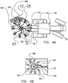
- Fig. 2 shows a cross-sectional view of a central part of the rotor 28.
- the frame beam 22 is fixedly connected to a stationary cover 64, which has an opening 66, in which the shaft 68 is mounted via a friction bearing 70.
- the shaft 68 defines the rotation axis A.
- the shaft 68 is fixedly connected to the swath curtain 56 via an outrigger arm 58.
- the shaft 68 is fixedly connected to the chassis 36 of the wheel assembly 34 (not shown in figure 2 ).
- the shaft 68, the swath curtain 56 and the wheel assembly 34 (and also the lever 60) can swivel together about the rotation axis A with respect to the frame 12.
- the cover 64 accommodates a pinion 74 at the end of the drive shaft 32, which engages a crown wheel 78 fixedly connected on top of a rotor housing 80.
- the rotor housing 80 accommodates a control cam arrangement 82 having a cam track, which is fixedly connected to the shaft 68.
- the rotor housing 80 is rotatably connected to the shaft 68 by means of roller bearings 72.
- the tine arms 30 and the tines 50 are tilted downwards and upwards for defining a predetermined depositing zone 86 of a path of the tines 50 for depositing of raked products (see fig. 3A ).
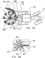
- Fig. 3A shows the tractor 16 pulling the haymaking machine 10 in a straight line.
- the wheel assembly 34 follows the path of the tractor 16 and is aligned in the central position.
- the tractor 16 has entered a curve to the right and in Fig. 5A a curve to the left.
- the wheel assembly 34 is aligned in such a manner that the wheels 40, 42 generally follow the path of the tractor 16. Since the swath curtain 56 and the control cam arrangement 82 are fixedly connected to the wheel assembly 34 by means of the shaft 68, the swath curtain 56 is continuously maintained in the same position and orientation with respect to the depositing zone 86 of the path of the tines 50.
- Fig. 3A shows a swath curtain support 88, which is entirely optional and therefore not shown in the other figures.
- the swath curtain support 88 may carry some of the curtain forces and/or supports the outrigger arm 58.
- the frame beam 22 may slide with respect to the swath curtain support 88.
- the swath curtain support 88 comprises a rod 90 that extends substantially horizontally and/or may be fixedly connected to the coupling device 14.
- Fig. 3B , 4B and 5B show the position of the lever 60 of Fig. 3A , 4A and 5A , respectively.
- the lever 60 In Fig. 3B , when the haymaking machine 10 travels along a straight line, the lever 60 is in the central position.
- the lever 60 In Fig. 4B and 5B , the lever 60 is swung out of the central position.
- the wheel assembly 34, and thus also the control cam arrangement 82 and the swath curtain 56, are biased by the spring 62 to the central position.
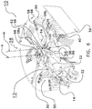
- Fig. 6 shows another embodiment of a haymaking machine 10, which has a semicircular swath curtain support 88.
- the swath curtain support 88 comprises a semicircular rod 90, which, at a first end, is connected with the coupling device 14 and, at a second end, is connected to a cantilever 92, which extends in a direction opposite to the direction of travel.
- a guiding ring 94 which also may be seen as a part of the swath curtain support 88 is mounted to the frame beam 22.
- the guiding ring 94 (similar to the rod 90) surrounds the rotation axis A in a circular manner and/or the outrigger arm 58 may slide with respect to the guiding ring 94.
- the guiding ring 94 carries a stop 96, which may be a pin that may be positioned in one of a series of holes provided in the guiding ring 94.
- the outrigger arm 58 comprises an inner arm portion 58a and an outer arm portion 58b connected by means of a hinge 98.
- the hinge 98 defines a pivot axis H which extends at a distance and substantially parallel to the rotation axis A.
- the outrigger arm 58 with the swath curtain 56 fixedly connected thereto swivels about the rotation axis A with respect to the frame 12.
- the outrigger arm 58 which is fixedly connected to the shaft 68, swivels with respect to the frame beam 22 about the rotation axis A as long as the outer arm portion 58b is not in contact with the stop 96.
- the outer arm portion 58b runs against the stop 96, it pivots with respect to the inner arm portion 58a about the pivot axis H of the hinge 98 so that the swath curtain 56 is prevented from swivelling further towards the coupling device 14.
- the swath curtain 56 stays behind with respect to the wheel assembly 34. Thereby, the swath curtain 56 is prevented from colliding with a rear wheel of the tractor 16.
- a spring element 100 biases the inner arm portion 58a and the outer arm portion 58b of the outrigger arm 58 to an extended position in line with each other, which runs transversely to the direction of travel so that the swath curtain 56 has the desired lateral position and orientation.
- the stop 96 moves the outer arm portion 58b of the outrigger arm 58 against the biasing force of the spring element 100 when the tractor 16 enters a sharp curve as described above.
Description
- The invention relates to a haymaking machine, particularly for windrowing harvested agricultural crops, such as hay. For example, the haymaking machine is a rotary rake or rotary swather.
-
US4914901 discloses a haymaking machine comprising a frame having at least one raking wheel. The frame is connected to a three-point hitching bracket that can be coupled to the lifting device of a drive tractor. The raking wheel includes a central casing having bearings in which tool-carrying arms directed outward are housed. Each of these arms carries at its outer end tools consisting of raking teeth. The inner end of each arm is accommodated inside the casing and includes a crank equipped with a roller. The casing is guided in rotation on an approximately vertical shaft, which determines the rotation axis of the raking wheel. The casing accommodates a control cam for the tool-carrying arms. The control cam is fastened to the shaft and includes a cam surface in which the rollers of the tool-carrying arms move. The lower end of the shaft is connected to a wheel assembly which rests on the ground. The wheel assembly, shaft and control cam are connected rigidly to one another and form an assembly that can swivel around the rotation axis. During operation, when the tractor and the machine enter a curve or a turn, the wheel assembly orientates itself in the direction of movement imposed by the tractor. Simultaneously, this wheel assembly causes the shaft to pivot around the rotation axis. The shaft then automatically moves the control cam which is fastened to it. The control cam is thus constantly oriented as a function of the direction that the tractor follows. Consequently, the depositing zone where the windrow is formed can vary in relation to the frame of the machine. However, this haymaking machine does not include a swath curtain, so that the windrows formed may still be irregular and scattered, in particular in curves or a turn. - It is an object of the invention to provide an improved haymaking machine, in particular for use in mountain areas.
- This object is achieved by a haymaking machine, particularly for windrowing harvested agricultural crops, such as a rotary rake, the haymaking machine comprising:
- a frame having a coupling device for coupling the haymaking machine to a tractor, for example a three-point coupling device;
- at least one rotor being connected to the frame in such a manner that the rotor can be driven in rotation about a rotation axis, in particular by means of a drive shaft that can be driven by a motor of the tractor, the rotor comprising a rotor housing and a plurality of tine arms extending radially from the rotor housing and carrying tines at their outer ends,
- a shaft extending through the rotor housing and defining the rotation axis,
- a control cam arrangement, which can also be referred to as control cam, accommodated in the rotor housing and fixedly connected to the shaft, the control cam arrangement having a cam track, the tine arms being connected to the cam track such that when the rotor is driven in rotation the tine arms rotate or pivot by means of the cam track about their respective longitudinal axes so that the tine arms lift the tines carried by said tine arms in a predetermined depositing zone of a path of said tines for depositing of raked products,
- a wheel assembly fixedly attached to the shaft,
- The haymaking machine according to the invention comprises a windrowing deflector, which can also be referred to as swath board or swath curtain. In general, a windrowing deflector extends along the depositing zone of the tines in a longitudinal direction of the haymaking machine. The windrowing deflector may collect crop delivered by the tines of the rotor. A windrowing deflector as such is known. However, contrary to known windrowing deflectors, which are generally securely fastened to the frame of the haymaking machine, the windrowing deflector according to the invention is fastened to the swivel assembly so that it swivels about the rotation axis with respect to the frame, together with the shaft, the control cam arrangement and the wheel assembly. Thereby, the windrowing deflector according to the invention is controlled in such a manner that the windrowing deflector is maintained in an optimal position and/or orientation along the depositing zone of the path of the tines irrespective of whether the tractor drives along a straight line or in curves or in a turn. When the tractor follows a curve, the wheel assembly having wheels or other supports supporting on the ground, positions the cam track of the control cam arrangement in such a manner that the depositing zone of the path of the tines is maintained substantially transversely to the curve, i.e. in the desired position and/or orientation for forming the windrow. At the same time, the wheel assembly also controls the windrowing deflector for maintaining the windrowing deflector in the desired position and/or orientation next to the depositing zone. As a result, the formed windrow is well-formed and regular in curves as well.
- It is preferred according to the invention that the coupling device of the frame is configured to connect the frame to the tractor in such a manner that the frame cannot swivel outwards with respect to the tractor. The coupling device is constructed such that the frame of the haymaking machine can be fixedly connected to the tractor, at least as seen in a horizontal plane. The coupling device of the frame is designed in a non-turnable manner with respect to the tractor, i.e. the frame cannot swivel with respect to the tractor about a substantially vertical axis. As a result, the coupling device can be of a simple fixed design type, so that the weight of the haymaking machine is kept relatively low. This is particularly advantageous for use in mountain areas.
- According to an embodiment of the invention, the coupling device comprises a three point attachment device mountable to a three point linkage of the tractor. For example, the three point attachment device may comprise a U-shaped headstock that on the lower end of the legs may be mounted to two lower lifting arms of the three point linkage of the tractor. The yoke of the U-shaped element may be connected to the top link. The drive shaft for driving the rotor of the haymaking machine may extend through the U-shaped headstock and is to be coupled to the tractor.
- In an embodiment of the invention, the windrowing deflector comprises a deflector surface extending substantially parallel to the rotation axis, i.e. vertically when the haymaking machine rests on a horizontal ground surface. In a further embodiment of the invention, the deflector surface extends substantially tangentially with respect to the path of the tines. The deflector surface may be formed, for example, by a screen made of cloth or of sheet metal or of flexible rods placed side by side.
- In a preferred embodiment of the invention, the windrowing deflector is fixedly connected to the shaft of the rotor. Thereby, the windrowing deflector can be secured to the swivel assembly in a robust and reliable manner. For example, the windrowing deflector is fixedly connected to the shaft by means of an outrigger arm which projects radially from the shaft. This is cost-effective. An inner end of the outrigger arm is secured to the shaft, whereas the outer end of the outrigger arm is fastened to the windrowing deflector. However, it is also possible according to the invention for the windrowing deflector to be connected to another part of the swivel assembly, for example the wheel assembly.
- It is preferred according to the invention that the haymaking machine comprises a centring device for biasing the swivel assembly to a central position in alignment with a longitudinal direction of the frame. In the central position, the swivel assembly, in particular the wheel assembly and also the windrowing deflector, are aligned with the longitudinal direction of the frame. When the tractor moves in a straight line, the centring device prevents relatively small swivelling or oscillating movements of the rotary rake out of the central position due to irregularities in the ground. Only when the tractor enters a curve or a turn, the wheel assembly and thereby the shaft, the control cam arrangement and the windrowing deflector are swivelled together about the rotation axis.
- The centring device can be constructed in a number of ways. For example, the centring device may comprise a lever being fixedly connected to the swivel assembly and projecting radially from the rotation axis, wherein said lever in the central position of the swivel assembly extends in the longitudinal direction of the frame towards the coupling device, and a pretensioning element which is pretensioned between the lever and the frame. The pretensioning element may be, for example, a spring or a hydraulic cylinder combined with an accumulator. A centring device of this type is cost-effective and reliable.
- According to an embodiment of the invention, the haymaking machine may comprise a stop which is fixedly connected to the frame, wherein the outrigger arm, which fixedly connects the windrowing deflector to the shaft comprises an inner arm portion and an outer arm portion pivotally connected by means of a hinge, preferably having a pivot axis extending substantially parallel to the rotation axis of the rotor, such that, when the outrigger arm abuts against the stop due to a swivelling movement of the swivel assembly towards the coupling device, the outer arm portion pivots about the hinge with respect to the inner arm portion. As a result, the windrowing deflector is prevented from swivelling further towards the coupling device. Thereby, the windrowing deflector is prevented from colliding against a rear wheel of the tractor.
- According to an embodiment of the invention, the inner arm portion and the outer arm portion of the outrigger arm may be biased towards an extended position in line with one another. For example, the inner arm portion and the outer arm portion are biased to the extended position by means of a spring. Thus, the inner arm portion and the outer arm portion of the outrigger arm are maintained in the extended position until the tractor enters such a sharp turn that the outer arm portion moves against the stop so that it is pivoted about the hinge, against the bias force, with respect to the inner arm portion. Incidentally, the bias force also causes the outer arm portion to be pivoted back into the extended position when the tractor returns to a straight line.
- According to an embodiment of the invention, the wheel assembly comprises at least three or four ground supporting wheels. The lower end of the shaft of the rotary rake may be fixedly connected to a chassis with two laterally extending arms, each of which carries one or two wheels.
- According to an embodiment of the invention, the tine arms are bent in such a manner that the outer end of each tine arm carrying the tines, when pivoted about its longitudinal axis so that the tines extend substantially vertically, is situated below an inner end of said tine arm being connected to the cam track. The outer end of each tine arm is lifted upwards, when the tines of said tine arm are pivoted upwards. This increases the space below the haymaking machine.
- The invention further relates to a method for windrowing harvested agricultural crops using a haymaking machine as described above. This method has the same advantages as described above in respect of the haymaking machine. In particular, the windrow formed by the method according to the invention is particularly well-formed and regular in straight lines as well as in curves or a turn.
- These and other aspects of the invention will be apparent from and elucidated with reference to the embodiments described hereinafter.
- The subject-matter of the invention will be explained in more detail with reference to exemplary embodiments which are illustrated in the attached drawings.
-
Fig. 1 shows a perspective view of a haymaking machine according to one embodiment of the invention. -
Fig. 2 shows a simplified cross-sectional view of a central part of the haymaking machine shown inFig. 1 . -
Fig. 3A shows a top view of the haymaking machine ofFig. 1 in a central position. -
Fig. 3B shows a detail ofFig. 3A . -
Fig. 4A shows a top view of the haymaking machine ofFig. 1 in a first swung-out position. -
Fig. 4B shows a detail ofFig. 4A . -
Fig. 5A shows a top view of the haymaking machine ofFig. 1 in a second swung-out position. -
Fig. 5B shows a detail ofFig. 5A . -
Fig. 6 shows a perspective view of a haymaking machine according to another embodiment of the invention. -
Fig. 1 shows ahaymaking machine 10, particularly for windrowing harvested agricultural crops, such as grass or hay. In this exemplary embodiment, thehaymaking machine 10 is a rotary rake having asingle rotor 28. Thehaymaking machine 10 comprises aframe 12 with a U-shaped three-point coupling device 14 at a front end for mounting thehaymaking machine 10 to a three-point linkage of a tractor 16 (see alsofigure 3A ). The three-point linkage of thetractor 16 comprises twolower lifting arms 18 and a top link (not shown inFig. 1 ). By means of thiscoupling device 14, theframe 12 of thehaymaking machine 10 cannot turn about a vertical axis with respect to thetractor 16, i.e. theframe 12 cannot swivel to the left or right with respect to thetractor 16, it can only be lifted and lowered by means of the three-point linkage of thetractor 16. - The
frame 12 furthermore comprises aframe beam 22 extending in a longitudinal direction from ayoke 24 of thecoupling device 14 to agear box 26 of therotor 28. Inside thegear box 26, means for rotating therotor 28 and for pivotingtine arms 30 of therotor 28 are provided, which may be driven via adrive shaft 32, which, in this exemplary embodiment, extends below theframe beam 22. Thedrive shaft 32 can be driven in rotation by means of a motor of thetractor 16. Thetine arms 30 of therotor 28 can be driven in rotation about a rotation axis A, which extends substantially in a vertical direction when thehaymaking machine 10 rests on a horizontal ground surface. - The
haymaking machine 10 comprises awheel assembly 34, which can be swivelled about the rotation axis A, independently from the rotation of thetine arms 30. Thewheel assembly 34 comprises achassis 36 with two laterally extendingarms 38. The laterally extendingarms 38 carry threeground supporting wheels rear wheel 42 may be an adjustable steering wheel, which can be displaced towards and away from thefront wheel 40 via atelescopic rod 44. One or more of thewheels 40 may be adjustable for height adjustments and/or other adjustments of therotor 28. Thewheels 40 are situated below therotor 28. - The
tine arms 30 have aninner end 46 and anouter end 48, which extend substantially horizontal. Theouter end 48 carriestines 50 forming arake 52. An intermediate portion 54 of thetine arms 30 is interconnected between theinner end 46 and theouter end 48. The intermediate portions 54 of thetine arms 30 form bended sections to increase the space between the ground and therotor 28. - The
rotor 28 furthermore comprises awindrowing deflector 56, also referred to as swath board or swath curtain. Theswath curtain 56 is fixedly connected to thewheel assembly 34, as will be explained in more detail below, such that theswath curtain 56 can be swivelled about the rotation axis A together with thewheel assembly 34 with respect to theframe 12. Alever 60 is fixedly connected to ashaft 68 which extends through the gear box 26 (seefigure 2 ). Thewheel assembly 34 and theswath curtain 56 are biased to a central position by means of aspring 62 which is connected between thelever 60 and theframe beam 22. With thehaymaking machine 10 in its central position (seefig. 1 and3A ), thelever 60 extends substantially in the longitudinal direction of theframe beam 22. -
Fig. 2 shows a cross-sectional view of a central part of therotor 28. Theframe beam 22 is fixedly connected to astationary cover 64, which has anopening 66, in which theshaft 68 is mounted via afriction bearing 70. Theshaft 68 defines the rotation axis A. At its upper end, theshaft 68 is fixedly connected to theswath curtain 56 via anoutrigger arm 58. At its lower end, theshaft 68 is fixedly connected to thechassis 36 of the wheel assembly 34 (not shown infigure 2 ). Thus, theshaft 68, theswath curtain 56 and the wheel assembly 34 (and also the lever 60) can swivel together about the rotation axis A with respect to theframe 12. - The
cover 64 accommodates apinion 74 at the end of thedrive shaft 32, which engages acrown wheel 78 fixedly connected on top of arotor housing 80. Therotor housing 80 accommodates acontrol cam arrangement 82 having a cam track, which is fixedly connected to theshaft 68. Therotor housing 80 is rotatably connected to theshaft 68 by means ofroller bearings 72. When therotor housing 80 is driven in rotation via thecrown wheel 78 driven by thepinion 74, thetine arms 30, which are supported by therotor housing 80, are rotated along their longitudinal axes by the cam track. In particular,rollers 84 at the end of thetine arms 30 are lifted and lowered by the cam track as they are guided inside the cam track. Thus, during the rotating movement of thetine arms 30 about the rotation axis A, thetine arms 30 and thetines 50 are tilted downwards and upwards for defining apredetermined depositing zone 86 of a path of thetines 50 for depositing of raked products (seefig. 3A ). - The following figures show the operation of the
haymaking machine 10 in curves and bends. -
Fig. 3A shows thetractor 16 pulling thehaymaking machine 10 in a straight line. Thewheel assembly 34 follows the path of thetractor 16 and is aligned in the central position. InFig. 4A , thetractor 16 has entered a curve to the right and inFig. 5A a curve to the left. In both cases, thewheel assembly 34 is aligned in such a manner that thewheels tractor 16. Since theswath curtain 56 and thecontrol cam arrangement 82 are fixedly connected to thewheel assembly 34 by means of theshaft 68, theswath curtain 56 is continuously maintained in the same position and orientation with respect to the depositingzone 86 of the path of thetines 50. - Additionally,
Fig. 3A shows aswath curtain support 88, which is entirely optional and therefore not shown in the other figures. Theswath curtain support 88 may carry some of the curtain forces and/or supports theoutrigger arm 58. Theframe beam 22 may slide with respect to theswath curtain support 88. Theswath curtain support 88 comprises arod 90 that extends substantially horizontally and/or may be fixedly connected to thecoupling device 14. -
Fig. 3B ,4B and5B show the position of thelever 60 ofFig. 3A ,4A and5A , respectively. InFig. 3B , when thehaymaking machine 10 travels along a straight line, thelever 60 is in the central position. InFig. 4B and5B , thelever 60 is swung out of the central position. Thewheel assembly 34, and thus also thecontrol cam arrangement 82 and theswath curtain 56, are biased by thespring 62 to the central position. -
Fig. 6 shows another embodiment of ahaymaking machine 10, which has a semicircularswath curtain support 88. Theswath curtain support 88 comprises asemicircular rod 90, which, at a first end, is connected with thecoupling device 14 and, at a second end, is connected to acantilever 92, which extends in a direction opposite to the direction of travel. - Furthermore, a guiding
ring 94, which also may be seen as a part of theswath curtain support 88 is mounted to theframe beam 22. The guiding ring 94 (similar to the rod 90) surrounds the rotation axis A in a circular manner and/or theoutrigger arm 58 may slide with respect to the guidingring 94. The guidingring 94 carries astop 96, which may be a pin that may be positioned in one of a series of holes provided in the guidingring 94. Theoutrigger arm 58 comprises aninner arm portion 58a and anouter arm portion 58b connected by means of ahinge 98. Thehinge 98 defines a pivot axis H which extends at a distance and substantially parallel to the rotation axis A. - When the
tractor 16 enters a curve, theoutrigger arm 58 with theswath curtain 56 fixedly connected thereto swivels about the rotation axis A with respect to theframe 12. Theoutrigger arm 58, which is fixedly connected to theshaft 68, swivels with respect to theframe beam 22 about the rotation axis A as long as theouter arm portion 58b is not in contact with thestop 96. When theouter arm portion 58b runs against thestop 96, it pivots with respect to theinner arm portion 58a about the pivot axis H of thehinge 98 so that theswath curtain 56 is prevented from swivelling further towards thecoupling device 14. As thewheel assembly 34 swivels further, theswath curtain 56 stays behind with respect to thewheel assembly 34. Thereby, theswath curtain 56 is prevented from colliding with a rear wheel of thetractor 16. - A
spring element 100 biases theinner arm portion 58a and theouter arm portion 58b of theoutrigger arm 58 to an extended position in line with each other, which runs transversely to the direction of travel so that theswath curtain 56 has the desired lateral position and orientation. Thestop 96 moves theouter arm portion 58b of theoutrigger arm 58 against the biasing force of thespring element 100 when thetractor 16 enters a sharp curve as described above. - While the invention has been illustrated and described in detail in the drawings and foregoing description, such illustration and description are to be considered illustrative or exemplary and not restrictive. The scope of protection is defined by the claims, i.e. the invention is not limited to the disclosed embodiments. Other variations to the disclosed embodiments can be understood and effected by those skilled in the art and practising the claimed invention, from a study of the drawings, the disclosure, and the appended claims. Any reference signs in the claims should not be construed as limiting the scope.
wherein the haymaking machine comprises a windrowing deflector extending next to or along the depositing zone, the windrowing deflector being fixedly connected to said swivel assembly, so that the windrowing deflector forms a part of said swivel assembly, for maintaining the windrowing deflector in a predetermined and/or stationary position and/or orientation with respect to the depositing zone when the swivel assembly swivels about the rotation axis with respect to the frame.
Claims (15)
- A haymaking machine (10), particularly for windrowing harvested agricultural crops, such as a rotary rake, the haymaking machine (10) comprising:- a frame (12) having a coupling device (14) for coupling the haymaking machine (10) to a tractor (16);- at least one rotor (28) being connected to the frame (12) in such a manner that the rotor (28) can be driven in rotation about a rotation axis (A), the rotor (28) comprising a rotor housing (80) and a plurality of tine arms (30) extending radially from the rotor housing (80) and carrying tines (50) at their outer ends,- a shaft (68) extending through the rotor housing (80) and defining the rotation axis (A),- a control cam arrangement (82) accommodated in the rotor housing (80) and fixedly connected to the shaft (68), the control cam arrangement (82) having a cam track, the tine arms (30) being connected to the cam track such that when the rotor (28) is driven in rotation the tine arms (30) rotate by means of the cam track (82) about their respective longitudinal axes for defining a predetermined depositing zone of a path of said tines (50) for depositing of raked products,- a wheel assembly (34) fixedly attached to the shaft (68),wherein the shaft (68), the control cam arrangement (82) and the wheel assembly (34), being fixedly connected to one another, form a swivel assembly (68, 82, 34) that can swivel about the rotation axis (A) with respect to the frame (12),
characterised in that the haymaking machine (10) comprises a windrowing deflector (56) extending along the depositing zone, the windrowing deflector (56) being fixedly connected to said swivel assembly (68, 82, 34) for maintaining the windrowing deflector (56) along the depositing zone when the swivel assembly (68, 82, 34) swivels about the rotation axis (A) with respect to the frame (12). - A haymaking machine as claimed in claim 1, wherein the coupling device of the frame (12) is configured to connect the frame (12) to the tractor in such a manner that the frame (12) cannot swivel laterally with respect to the tractor.
- A haymaking machine as claimed in claim 1 or 2, wherein the coupling device of the frame (12) comprises a three point attachment device (14) mountable to a three point linkage of the tractor (16).
- A haymaking machine as claimed in one or more of the preceding claims, wherein the windrowing deflector (56) comprises a deflector surface extending substantially parallel to the rotation axis (A).
- A haymaking machine as claimed in claim 4, wherein the deflector surface extends substantially tangentially with respect to the path of the tines (50).
- A haymaking machine as claimed in one or more of the preceding claims, wherein the windrowing deflector (56) is fixedly connected to the shaft (68) of the rotor (28).
- A haymaking machine as claimed in claim 6, wherein the windrowing deflector (56) is fixedly connected to the shaft (68) by means of an outrigger arm projecting radially from the shaft (68).
- A haymaking machine as claimed in one or more of the preceding claims, wherein the haymaking machine comprises a centring device for biasing the swivel assembly (68, 82, 34, 56) to a central position in alignment with a longitudinal direction of the frame.
- A haymaking machine as claimed in claim 8, wherein the centring device comprises:- a lever being fixedly connected to the swivel assembly and projecting radially from the rotation axis (A), wherein said lever in the central position of the swivel assembly extends in the longitudinal direction of the frame towards the coupling device, and- a pretensioning element which is pretensioned between the lever and the frame.
- A haymaking machine as claimed in claim 7, wherein the haymaking machine (10) comprises a stop (96) which is fixedly connected to the frame (12), and wherein the outrigger arm (58) comprises an inner arm portion (58a) and an outer arm portion (58b) pivotally connected by means of a hinge (98), such that, when the outrigger arm (58) abuts against the stop (96) due to a swivelling movement of the swivel assembly towards the coupling device (14), the outer arm portion pivots about the hinge (98) with respect to the inner arm portion.
- A haymaking machine as claimed in claim 10, wherein the inner arm portion and the outer arm portion of the outrigger arm (58) are biased towards an extended position in line with one another.
- A haymaking machine as claimed in one or more of the preceding claims, wherein the wheel assembly (34) comprises at least three or four wheels (40).
- A haymaking machine as claimed in one or more of the preceding claims, wherein the tine arms (30) are bent in such a manner that the outer end of each tine arm (30) carrying the tines (52), when pivoted about its longitudinal axis to a position with substantially vertically extending tines (52), is situated below an inner end of said tine arm (30) being connected to the cam track (82).
- A haymaking machine as claimed in one or more of the preceding claims, wherein the swivel assembly (68, 82, 34, 56) can be swivelled about the rotation axis (A) with respect to the frame (12) independently from any rotation of the rotor (28) about the rotation axis (A).
- A method for windrowing harvested agricultural crops using a haymaking machine as claimed in one of the preceding claims.
Applications Claiming Priority (1)
| Application Number | Priority Date | Filing Date | Title |
|---|---|---|---|
| NL2014732A NL2014732B1 (en) | 2015-04-29 | 2015-04-29 | Agricultural raking device. |
Publications (2)
| Publication Number | Publication Date |
|---|---|
| EP3087823A1 EP3087823A1 (en) | 2016-11-02 |
| EP3087823B1 true EP3087823B1 (en) | 2018-02-28 |
Family
ID=53783829
Family Applications (1)
| Application Number | Title | Priority Date | Filing Date |
|---|---|---|---|
| EP16167058.3A Not-in-force EP3087823B1 (en) | 2015-04-29 | 2016-04-26 | Agricultural raking device |
Country Status (2)
| Country | Link |
|---|---|
| EP (1) | EP3087823B1 (en) |
| NL (1) | NL2014732B1 (en) |
Cited By (1)
| Publication number | Priority date | Publication date | Assignee | Title |
|---|---|---|---|---|
| US20210307228A1 (en) * | 2018-08-07 | 2021-10-07 | Kverneland Group Kerteminde As | Agricultural working apparatus |
Family Cites Families (5)
| Publication number | Priority date | Publication date | Assignee | Title |
|---|---|---|---|---|
| NL7412051A (en) * | 1966-12-23 | 1974-12-30 | ||
| CH450793A (en) * | 1967-06-19 | 1968-01-31 | Bucher Guyer Ag Masch | Haymaking machine |
| FR2632810B2 (en) * | 1987-11-17 | 1991-08-30 | Kuhn Sa | FENAISON MACHINE WITH AT LEAST ONE RAKING WHEEL EQUIPPED WITH CONTROLLED TOOL HOLDER ARMS |
| FR2632155B1 (en) * | 1988-06-03 | 1991-10-11 | Kuhn Sa | FENAISON MACHINE HAVING A ROTOR FOR RAKING |
| FR2678804B1 (en) * | 1991-07-11 | 1998-09-18 | Kuhn Sa | HATCHING MACHINE COMPRISING AT LEAST ONE RAKING WHEEL, A PROTECTION DEVICE AND AN ADJUSTABLE DEFLECTOR. |
-
2015
- 2015-04-29 NL NL2014732A patent/NL2014732B1/en not_active IP Right Cessation
-
2016
- 2016-04-26 EP EP16167058.3A patent/EP3087823B1/en not_active Not-in-force
Non-Patent Citations (1)
| Title |
|---|
| None * |
Cited By (1)
| Publication number | Priority date | Publication date | Assignee | Title |
|---|---|---|---|---|
| US20210307228A1 (en) * | 2018-08-07 | 2021-10-07 | Kverneland Group Kerteminde As | Agricultural working apparatus |
Also Published As
| Publication number | Publication date |
|---|---|
| NL2014732A (en) | 2016-11-07 |
| EP3087823A1 (en) | 2016-11-02 |
| NL2014732B1 (en) | 2017-01-18 |
Similar Documents
| Publication | Publication Date | Title |
|---|---|---|
| CA2934635C (en) | Agricultural machine | |
| US9485908B2 (en) | Secondary cutting device arrangement for an agricultural harvesting machine | |
| US20060254244A1 (en) | Agricultural machine for swathing products lying on the ground | |
| US8276356B2 (en) | Tractor mounted cotton harvester | |
| US4922700A (en) | Haymaking machine | |
| US4330984A (en) | Crop divider assembly | |
| US6748730B2 (en) | Haymaking machine with telescopic carrier arms | |
| US3611690A (en) | Agricultural implement such as a haymaker | |
| US5862659A (en) | Haymaking machine with at least one windrowing rotor | |
| CA2890534C (en) | Device for harvesting long agricultural products and agricultural self-propelled unit for harvesting agricultural products comprising the device | |
| EP3087823B1 (en) | Agricultural raking device | |
| EP3811766A1 (en) | Improved agricultural implement | |
| US6131379A (en) | Reel-type lawn mower and tractor assembly and method for reducing lateral tilting moment on the mower | |
| EP3622803B1 (en) | Improved agricultural implement | |
| US4907400A (en) | Agricultural mower having means for raising the reel to a clearing height when the cutter bar engages an obstacle | |
| US2746230A (en) | Adjustable cutter means having crop lifting means | |
| EP1668977B1 (en) | A hay-making machine | |
| US3599405A (en) | Header suspension | |
| EP3669635B1 (en) | Combine header with adjustable reel | |
| US8578690B2 (en) | Haymaking machine provided with a hitching device with an inclined pivoting axis | |
| EP0507408B1 (en) | An agricultural machine | |
| EP0713640A1 (en) | A hay-making machine | |
| AU741684B2 (en) | An implement for displacing crop lying on the soil | |
| US2869652A (en) | Root crop harvester | |
| EP2181577A1 (en) | Mobile mowing machine comprising fixed and pivoting mowing units |
Legal Events
| Date | Code | Title | Description |
|---|---|---|---|
| PUAI | Public reference made under article 153(3) epc to a published international application that has entered the european phase |
Free format text: ORIGINAL CODE: 0009012 |
|
| AK | Designated contracting states |
Kind code of ref document: A1 Designated state(s): AL AT BE BG CH CY CZ DE DK EE ES FI FR GB GR HR HU IE IS IT LI LT LU LV MC MK MT NL NO PL PT RO RS SE SI SK SM TR |
|
| AX | Request for extension of the european patent |
Extension state: BA ME |
|
| 17P | Request for examination filed |
Effective date: 20170502 |
|
| RBV | Designated contracting states (corrected) |
Designated state(s): AL AT BE BG CH CY CZ DE DK EE ES FI FR GB GR HR HU IE IS IT LI LT LU LV MC MK MT NL NO PL PT RO RS SE SI SK SM TR |
|
| STAA | Information on the status of an ep patent application or granted ep patent |
Free format text: STATUS: REQUEST FOR EXAMINATION WAS MADE |
|
| GRAP | Despatch of communication of intention to grant a patent |
Free format text: ORIGINAL CODE: EPIDOSNIGR1 |
|
| STAA | Information on the status of an ep patent application or granted ep patent |
Free format text: STATUS: GRANT OF PATENT IS INTENDED |
|
| RIC1 | Information provided on ipc code assigned before grant |
Ipc: A01D 78/12 20060101ALI20170529BHEP Ipc: A01D 78/10 20060101AFI20170529BHEP |
|
| INTG | Intention to grant announced |
Effective date: 20170703 |
|
| GRAS | Grant fee paid |
Free format text: ORIGINAL CODE: EPIDOSNIGR3 |
|
| GRAA | (expected) grant |
Free format text: ORIGINAL CODE: 0009210 |
|
| STAA | Information on the status of an ep patent application or granted ep patent |
Free format text: STATUS: THE PATENT HAS BEEN GRANTED |
|
| AK | Designated contracting states |
Kind code of ref document: B1 Designated state(s): AL AT BE BG CH CY CZ DE DK EE ES FI FR GB GR HR HU IE IS IT LI LT LU LV MC MK MT NL NO PL PT RO RS SE SI SK SM TR |
|
| REG | Reference to a national code |
Ref country code: GB Ref legal event code: FG4D Ref country code: CH Ref legal event code: EP |
|
| REG | Reference to a national code |
Ref country code: AT Ref legal event code: REF Ref document number: 973106 Country of ref document: AT Kind code of ref document: T Effective date: 20180315 |
|
| REG | Reference to a national code |
Ref country code: IE Ref legal event code: FG4D |
|
| REG | Reference to a national code |
Ref country code: DE Ref legal event code: R096 Ref document number: 602016001692 Country of ref document: DE |
|
| REG | Reference to a national code |
Ref country code: NL Ref legal event code: MP Effective date: 20180228 |
|
| REG | Reference to a national code |
Ref country code: LT Ref legal event code: MG4D |
|
| REG | Reference to a national code |
Ref country code: AT Ref legal event code: MK05 Ref document number: 973106 Country of ref document: AT Kind code of ref document: T Effective date: 20180228 |
|
| PG25 | Lapsed in a contracting state [announced via postgrant information from national office to epo] |
Ref country code: LT Free format text: LAPSE BECAUSE OF FAILURE TO SUBMIT A TRANSLATION OF THE DESCRIPTION OR TO PAY THE FEE WITHIN THE PRESCRIBED TIME-LIMIT Effective date: 20180228 Ref country code: NL Free format text: LAPSE BECAUSE OF FAILURE TO SUBMIT A TRANSLATION OF THE DESCRIPTION OR TO PAY THE FEE WITHIN THE PRESCRIBED TIME-LIMIT Effective date: 20180228 Ref country code: ES Free format text: LAPSE BECAUSE OF FAILURE TO SUBMIT A TRANSLATION OF THE DESCRIPTION OR TO PAY THE FEE WITHIN THE PRESCRIBED TIME-LIMIT Effective date: 20180228 Ref country code: NO Free format text: LAPSE BECAUSE OF FAILURE TO SUBMIT A TRANSLATION OF THE DESCRIPTION OR TO PAY THE FEE WITHIN THE PRESCRIBED TIME-LIMIT Effective date: 20180528 Ref country code: HR Free format text: LAPSE BECAUSE OF FAILURE TO SUBMIT A TRANSLATION OF THE DESCRIPTION OR TO PAY THE FEE WITHIN THE PRESCRIBED TIME-LIMIT Effective date: 20180228 Ref country code: FI Free format text: LAPSE BECAUSE OF FAILURE TO SUBMIT A TRANSLATION OF THE DESCRIPTION OR TO PAY THE FEE WITHIN THE PRESCRIBED TIME-LIMIT Effective date: 20180228 Ref country code: CY Free format text: LAPSE BECAUSE OF FAILURE TO SUBMIT A TRANSLATION OF THE DESCRIPTION OR TO PAY THE FEE WITHIN THE PRESCRIBED TIME-LIMIT Effective date: 20180228 |
|
| PG25 | Lapsed in a contracting state [announced via postgrant information from national office to epo] |
Ref country code: LV Free format text: LAPSE BECAUSE OF FAILURE TO SUBMIT A TRANSLATION OF THE DESCRIPTION OR TO PAY THE FEE WITHIN THE PRESCRIBED TIME-LIMIT Effective date: 20180228 Ref country code: SE Free format text: LAPSE BECAUSE OF FAILURE TO SUBMIT A TRANSLATION OF THE DESCRIPTION OR TO PAY THE FEE WITHIN THE PRESCRIBED TIME-LIMIT Effective date: 20180228 Ref country code: RS Free format text: LAPSE BECAUSE OF FAILURE TO SUBMIT A TRANSLATION OF THE DESCRIPTION OR TO PAY THE FEE WITHIN THE PRESCRIBED TIME-LIMIT Effective date: 20180228 Ref country code: GR Free format text: LAPSE BECAUSE OF FAILURE TO SUBMIT A TRANSLATION OF THE DESCRIPTION OR TO PAY THE FEE WITHIN THE PRESCRIBED TIME-LIMIT Effective date: 20180529 Ref country code: BG Free format text: LAPSE BECAUSE OF FAILURE TO SUBMIT A TRANSLATION OF THE DESCRIPTION OR TO PAY THE FEE WITHIN THE PRESCRIBED TIME-LIMIT Effective date: 20180528 Ref country code: AT Free format text: LAPSE BECAUSE OF FAILURE TO SUBMIT A TRANSLATION OF THE DESCRIPTION OR TO PAY THE FEE WITHIN THE PRESCRIBED TIME-LIMIT Effective date: 20180228 |
|
| RAP2 | Party data changed (patent owner data changed or rights of a patent transferred) |
Owner name: FORAGE COMPANY B.V. |
|
| PG25 | Lapsed in a contracting state [announced via postgrant information from national office to epo] |
Ref country code: AL Free format text: LAPSE BECAUSE OF FAILURE TO SUBMIT A TRANSLATION OF THE DESCRIPTION OR TO PAY THE FEE WITHIN THE PRESCRIBED TIME-LIMIT Effective date: 20180228 Ref country code: IT Free format text: LAPSE BECAUSE OF FAILURE TO SUBMIT A TRANSLATION OF THE DESCRIPTION OR TO PAY THE FEE WITHIN THE PRESCRIBED TIME-LIMIT Effective date: 20180228 Ref country code: EE Free format text: LAPSE BECAUSE OF FAILURE TO SUBMIT A TRANSLATION OF THE DESCRIPTION OR TO PAY THE FEE WITHIN THE PRESCRIBED TIME-LIMIT Effective date: 20180228 Ref country code: PL Free format text: LAPSE BECAUSE OF FAILURE TO SUBMIT A TRANSLATION OF THE DESCRIPTION OR TO PAY THE FEE WITHIN THE PRESCRIBED TIME-LIMIT Effective date: 20180228 Ref country code: RO Free format text: LAPSE BECAUSE OF FAILURE TO SUBMIT A TRANSLATION OF THE DESCRIPTION OR TO PAY THE FEE WITHIN THE PRESCRIBED TIME-LIMIT Effective date: 20180228 |
|
| REG | Reference to a national code |
Ref country code: DE Ref legal event code: R119 Ref document number: 602016001692 Country of ref document: DE |
|
| PG25 | Lapsed in a contracting state [announced via postgrant information from national office to epo] |
Ref country code: SK Free format text: LAPSE BECAUSE OF FAILURE TO SUBMIT A TRANSLATION OF THE DESCRIPTION OR TO PAY THE FEE WITHIN THE PRESCRIBED TIME-LIMIT Effective date: 20180228 Ref country code: SM Free format text: LAPSE BECAUSE OF FAILURE TO SUBMIT A TRANSLATION OF THE DESCRIPTION OR TO PAY THE FEE WITHIN THE PRESCRIBED TIME-LIMIT Effective date: 20180228 Ref country code: CZ Free format text: LAPSE BECAUSE OF FAILURE TO SUBMIT A TRANSLATION OF THE DESCRIPTION OR TO PAY THE FEE WITHIN THE PRESCRIBED TIME-LIMIT Effective date: 20180228 Ref country code: MC Free format text: LAPSE BECAUSE OF FAILURE TO SUBMIT A TRANSLATION OF THE DESCRIPTION OR TO PAY THE FEE WITHIN THE PRESCRIBED TIME-LIMIT Effective date: 20180228 Ref country code: DK Free format text: LAPSE BECAUSE OF FAILURE TO SUBMIT A TRANSLATION OF THE DESCRIPTION OR TO PAY THE FEE WITHIN THE PRESCRIBED TIME-LIMIT Effective date: 20180228 |
|
| REG | Reference to a national code |
Ref country code: BE Ref legal event code: MM Effective date: 20180430 |
|
| PLBE | No opposition filed within time limit |
Free format text: ORIGINAL CODE: 0009261 |
|
| STAA | Information on the status of an ep patent application or granted ep patent |
Free format text: STATUS: NO OPPOSITION FILED WITHIN TIME LIMIT |
|
| REG | Reference to a national code |
Ref country code: IE Ref legal event code: MM4A |
|
| PG25 | Lapsed in a contracting state [announced via postgrant information from national office to epo] |
Ref country code: DE Free format text: LAPSE BECAUSE OF NON-PAYMENT OF DUE FEES Effective date: 20181101 Ref country code: LU Free format text: LAPSE BECAUSE OF NON-PAYMENT OF DUE FEES Effective date: 20180426 |
|
| 26N | No opposition filed |
Effective date: 20181129 |
|
| PG25 | Lapsed in a contracting state [announced via postgrant information from national office to epo] |
Ref country code: BE Free format text: LAPSE BECAUSE OF NON-PAYMENT OF DUE FEES Effective date: 20180430 Ref country code: SI Free format text: LAPSE BECAUSE OF FAILURE TO SUBMIT A TRANSLATION OF THE DESCRIPTION OR TO PAY THE FEE WITHIN THE PRESCRIBED TIME-LIMIT Effective date: 20180228 |
|
| PG25 | Lapsed in a contracting state [announced via postgrant information from national office to epo] |
Ref country code: FR Free format text: LAPSE BECAUSE OF NON-PAYMENT OF DUE FEES Effective date: 20180428 Ref country code: IE Free format text: LAPSE BECAUSE OF NON-PAYMENT OF DUE FEES Effective date: 20180426 |
|
| REG | Reference to a national code |
Ref country code: CH Ref legal event code: PL |
|
| PG25 | Lapsed in a contracting state [announced via postgrant information from national office to epo] |
Ref country code: CH Free format text: LAPSE BECAUSE OF NON-PAYMENT OF DUE FEES Effective date: 20190430 Ref country code: LI Free format text: LAPSE BECAUSE OF NON-PAYMENT OF DUE FEES Effective date: 20190430 Ref country code: MT Free format text: LAPSE BECAUSE OF NON-PAYMENT OF DUE FEES Effective date: 20180426 |
|
| PG25 | Lapsed in a contracting state [announced via postgrant information from national office to epo] |
Ref country code: TR Free format text: LAPSE BECAUSE OF FAILURE TO SUBMIT A TRANSLATION OF THE DESCRIPTION OR TO PAY THE FEE WITHIN THE PRESCRIBED TIME-LIMIT Effective date: 20180228 |
|
| PG25 | Lapsed in a contracting state [announced via postgrant information from national office to epo] |
Ref country code: PT Free format text: LAPSE BECAUSE OF FAILURE TO SUBMIT A TRANSLATION OF THE DESCRIPTION OR TO PAY THE FEE WITHIN THE PRESCRIBED TIME-LIMIT Effective date: 20180228 |
|
| PG25 | Lapsed in a contracting state [announced via postgrant information from national office to epo] |
Ref country code: HU Free format text: LAPSE BECAUSE OF FAILURE TO SUBMIT A TRANSLATION OF THE DESCRIPTION OR TO PAY THE FEE WITHIN THE PRESCRIBED TIME-LIMIT; INVALID AB INITIO Effective date: 20160426 Ref country code: MK Free format text: LAPSE BECAUSE OF NON-PAYMENT OF DUE FEES Effective date: 20180228 |
|
| PG25 | Lapsed in a contracting state [announced via postgrant information from national office to epo] |
Ref country code: IS Free format text: LAPSE BECAUSE OF FAILURE TO SUBMIT A TRANSLATION OF THE DESCRIPTION OR TO PAY THE FEE WITHIN THE PRESCRIBED TIME-LIMIT Effective date: 20180628 |
|
| GBPC | Gb: european patent ceased through non-payment of renewal fee |
Effective date: 20200426 |
|
| PG25 | Lapsed in a contracting state [announced via postgrant information from national office to epo] |
Ref country code: GB Free format text: LAPSE BECAUSE OF NON-PAYMENT OF DUE FEES Effective date: 20200426 |