EP1668977B1 - A hay-making machine - Google Patents
A hay-making machine Download PDFInfo
- Publication number
- EP1668977B1 EP1668977B1 EP05077622A EP05077622A EP1668977B1 EP 1668977 B1 EP1668977 B1 EP 1668977B1 EP 05077622 A EP05077622 A EP 05077622A EP 05077622 A EP05077622 A EP 05077622A EP 1668977 B1 EP1668977 B1 EP 1668977B1
- Authority
- EP
- European Patent Office
- Prior art keywords
- haymaking machine
- central
- wheel set
- frame
- rotor
- Prior art date
- Legal status (The legal status is an assumption and is not a legal conclusion. Google has not performed a legal analysis and makes no representation as to the accuracy of the status listed.)
- Not-in-force
Links
Images

Classifications
-
- A—HUMAN NECESSITIES
- A01—AGRICULTURE; FORESTRY; ANIMAL HUSBANDRY; HUNTING; TRAPPING; FISHING
- A01D—HARVESTING; MOWING
- A01D78/00—Haymakers with tines moving with respect to the machine
- A01D78/08—Haymakers with tines moving with respect to the machine with tine-carrying rotary heads or wheels
- A01D78/10—Haymakers with tines moving with respect to the machine with tine-carrying rotary heads or wheels the tines rotating about a substantially vertical axis
- A01D78/1042—Steering devices
Definitions
- the invention relates to a haymaking machine according to the preamble of claim 1.
- Such a haymaking machine is known from German patent application DE19730860-A1 .
- This known haymaking machine intended for being coupled behind a tractor comprises a central frame orientated in the longitudinal direction with a rake rotor disposed on both sides. These rotors are fastened to the central frame via arms and comprise a front rotor and a rear rotor.
- a coupling frame is rotatably disposed for coupling to the tractor.
- a wheel set for supporting the machine on the ground.
- This wheel set comprises a cross beam which is fixedly connected to the central frame, the two ends of said cross beam being provided with a wheel which is pivotable about a vertical axis.
- the two wheels are interconnected via a steering rod system.
- An elongated steering rod connects this steering rod system to the coupling frame.
- the orientation of the central frame relative to the coupling frame will be transmitted to the two wheels via the elongated steering rod and the steering rod system.
- a drawback of this haymaking machine is that steering of the wheels takes place via the coupling frame via a complicated construction comprising many axes of rotation.
- the invention aims inter alia at providing a haymaking machine having a simpler construction.
- a haymaking machine of the type mentioned in the preamble comprises the features of the characterizing part of claim 1. Owing to the fact that the entire wheel set is rotatable as a whole about a vertical wheel set axis, a steering rod is superfluous.
- the haymaking machine is capable of being put in a side delivery position in which, seen in the normal direction of travel, the working area of the rear rotor overlaps the working area of the front rotor.
- a side delivery position enables to produce wide swaths owing to the fact that the crop from two working runs can be deposited in one swath.
- working area is meant that part of the working width of the machine where the rotor exerts a raking function on the crop lying on the ground.
- the working area may depend, for example, on the orientation of the central frame or the way in which the rotor arms are controlled.
- the haymaking machine is capable of being put in a multiple swath position, in which the rotors are capable of being placed in such a way that the working area of the rear rotor is located at some distance beside the working area of the front rotor in such a way that a swath can be formed between the two rotors.
- the wheel set is fixed under an angle with the central frame, so that the machine will be located obliquely behind the tractor in the operative position. The rear rotor will thus be located at some distance from the front rotor and will, therefore, not pick up the crop from the front rotor.
- the central frame in the multiple swath position, is capable of being supported as a whole between two swaths on the ground via the central wheel set. There is thus created more space for the swath.
- This is in particular advantageous relative to wheel sets having two wheels and the swath to be formed being deposited between these wheels. The distance between the wheels of such a wheel set is limited, so that only relatively narrow swaths are possible.
- the rotors are rotatable in the same direction.
- the coupling frame comprises a vertical coupling axis and the wheel set is connected to the coupling frame via a drawbar, a rotation of the central frame about the coupling axis relative to the coupling frame realising a rotation of the wheel set in opposite direction relative to the frame.
- the produced part of the wheel axis intersects with the circumference of a rotor. This results in a relatively short construction which is easily manoeuvrable.
- the central wheel set comprises an offset-cylinder for rotation of the wheel set about the wheel set axis relative to the central frame.
- the arms are capable of being folded up for putting the haymaking machine in a transport position and the folding up axes are orientated parallel to the normal direction of travel of the haymaking machine in the transport position.
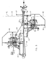
- Figure 1 shows a haymaking machine 1 for raking crop lying on the ground, comprising a central frame 2 which is capable of being supported on the ground via a central wheel set 3 and which, seen in the normal direction of travel, is disposed at the rear side of the haymaking machine 1, a coupling frame 4 for fastening to a tractor 5 and forming the connection between the tractor 5 and the central frame 2, and drivable rotors 6, 7 fastened to the central frame 2 via arms 8, 9, which rotors 6, 7 are provided with tine arms 10 with rake tines and comprise, seen in the longitudinal direction of the central frame 2, at least a front rotor 6 and a rear rotor 7, the central wheel set 3 being both rotatable and adjustable about a vertical wheel set axis 11 relative to the central frame 2.
- the tractor 5 is depicted only partially.
- the haymaking machine 1 is shown in the side delivery position in which, seen in the normal direction of travel R, the working area of the rear rotor 7 overlaps the working area of the front rotor 6.
- the central wheel set 3 comprises only one single wheel 12.
- the invention is not limited to a wheel set having one single wheel, but may comprise any arbitrarily chosen number of wheels, disposed on the same collective axis of rotation, as well as rotatable independently of each other about axes of rotation extending in line with each other, as well as rotatable about axes of rotation that are not orientated in line with each other.
- the produced part of the wheel axis of the wheel 12 intersects with the circumference of the rear rotor 7.
- the haymaking machine 1 is short and easily manoeuvrable.
- the arms 8, 9 are capable of being folded up for putting the haymaking machine 1 in a transport position ( Figure 5 ), in which the folding up axes 13, 14 are orientated parallel to the normal direction of travel R of the haymaking machine 1 in the transport position.
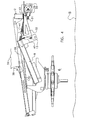
- Figure 2 shows the haymaking machine 1 of Figure 1 , put in the multiple swath position, the rotors 6, 7 being placed in such a way that the working area of the rear rotor 7 is located at some distance beside the working area of the front rotor 6 in such a way that a swath can be formed between the two rotors 6, 7.
- the central wheel set 3 is supported as a whole between two swaths on the ground.
- the wheel 12 is rotatable about a wheel set axis 11 and is capable of being fixedly disposed, the orientation of the central frame 2 relative to the tractor 5 can be changed.
- the two rotors 6, 7 rotate in the same direction of rotation D.
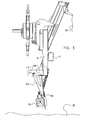
- FIG 3 shows the haymaking machine 1 of Figures 1 and 2 in detail in the side delivery position.
- the tine arms 10 with the tines fastened thereto are of the known controlled type.
- the rotors 6, 7 are supported on the ground, each via a rotor wheel set 15 having each four pivoting wheels.
- the two front pivoting wheels are fastened to a cross beam 16 which is capable of swivelling about a swivel axis 17 orientated in the direction of travel R. To enable proper functioning also in hilly terrain, the swivelling wheels are also capable of being fixed.
- the rotors 6, 7 are fastened to the central frame 2 via an arm 8, respectively 9.
- Said arm 8, respectively 9 comprises two arm portions 18, 19, respectively 20, 21, which are each connected to the central frame 2 by means of a hinge, the folding up axes 13, 14 extending through the two hinges.
- Said folding up axes 13, 14 intersect with the rotors 6, 7 in the operative position.
- the folding up axes 13, 14 are also disposed at some distance beside the central frame 2.
- the rotors 6, 7 are each capable of being put in a transport position with the aid of a folding up cylinder 22, 23, the rotor axis being orientated in a horizontal plane.
- the rotors 6, 7 are also capable of being placed in a headland position, in which position the rotor plane is lifted approximately half a meter parallel to the ground surface relative to the operative position.
- the coupling frame 4 is disposed at the front side of the central frame 2.
- the latter is capable of being coupled to a non-shown tractor via a known three-point linkage.
- Such a three-point linkage ensures a better stability in comparison with a linkage only made via the lifting arms of the tractor.
- the central frame 2 further comprises at the front side a horizontal pivot axis 24.
- the coupling frame 4 further comprises a vertically orientated coupling axis 25 and the central wheel set 3 is connected to the coupling frame 4 via a drawbar 26, a rotation of the central frame 2 about the coupling axis 25 relative to the coupling frame 4 realising a rotation in opposite direction of the central wheel set 3 relative to the central frame 2.
- the drive of at least the front rotor 6 comprises a longitudinal axis 29 which is substantially orientated in the longitudinal direction of the haymaking machine 1, a square gearbox 30 which is connected to the longitudinal axis 29 at the front side, and a square axis 31 forming the connection between the gearbox 30 and the rotor 6, the gearbox 30 being connected to a gearbox arm 32 and the gearbox arm 32 being movable independently of the arm 8.
- the gearbox arm 32 is movable about the folding up axis 13.
- the central frame 2 comprises a stop 42 for limiting the freedom of rotation of the gearbox arm 30 in at least the operative position.
- the drive of the rear rotor 7 takes place via a direct axial connection with the gearbox 30.
- the rear rotor 7 comprises a fixed coupling point 34 and the connection between said coupling point 34 and the gearbox 30 is formed by a standard telescopic coupling axis 33 with a cardan coupling provided at each connecting point.
- FIG. 4 shows the construction of the gearbox arm 32 in detail in Figures 4 and 5 as a cross-section along the line L in Figure 3 in the direction of the arrow K.
- Figure 4 shows the situation in the operative position, in which the rotor 6 assumes the lowest position, i.e. rests with the wheel set upon the ground.
- Figure 5 shows the situation in the transport position. For reasons of orientation also the ground B is indicated.
- the folding up cylinder 36 is energized so that the arm 8 is lifted. In this headland position, the rotor 6 is in line with the arm 8 and the gearbox arm 32. A stop on the folding up cylinder 36 prevents further folding up. At the upper side, the rotor 6 is connected to the gearbox arm 32 via a cable 37. This means that the rotor 6 remains parallel to the ground B during lifting to the headland position and further folding up of the rotor 6 against the gearbox arm 32 is prevented. In order to fold up the rotor 6 further, the stop on the folding up cylinder 36 is released via a lever 38. Said lever 38 is operated from the tractor 5 via a cord 39.
- the central frame 2 serves as a stop for the arm 8.
- the arm 8 further comprises a stop 40 for limiting the freedom of rotation of the gearbox arm 32 in at least the transport position. In the headland position, the arm 8 makes contact with the gearbox arm 32 via said stop 40.
- All stops are made of synthetic material in order to prevent the construction from being damaged.
- the invention is not limited to a haymaking machine having two rotors, but may also comprise more rotors. Furthermore, the invention is not limited to the type of rotor described.
Abstract
Description
- The invention relates to a haymaking machine according to the preamble of
claim 1. - Such a haymaking machine is known from
German patent application DE19730860-A1 . This known haymaking machine intended for being coupled behind a tractor comprises a central frame orientated in the longitudinal direction with a rake rotor disposed on both sides. These rotors are fastened to the central frame via arms and comprise a front rotor and a rear rotor. At the front side of the central frame, a coupling frame is rotatably disposed for coupling to the tractor. At the rear side of the frame, there is disposed a wheel set for supporting the machine on the ground. This wheel set comprises a cross beam which is fixedly connected to the central frame, the two ends of said cross beam being provided with a wheel which is pivotable about a vertical axis. The two wheels are interconnected via a steering rod system. An elongated steering rod connects this steering rod system to the coupling frame. When making a bend, the orientation of the central frame relative to the coupling frame will be transmitted to the two wheels via the elongated steering rod and the steering rod system. A drawback of this haymaking machine is that steering of the wheels takes place via the coupling frame via a complicated construction comprising many axes of rotation. - The invention aims inter alia at providing a haymaking machine having a simpler construction.
- To this end, according to the invention, a haymaking machine of the type mentioned in the preamble comprises the features of the characterizing part of
claim 1. Owing to the fact that the entire wheel set is rotatable as a whole about a vertical wheel set axis, a steering rod is superfluous. - According to a favourable embodiment, the haymaking machine is capable of being put in a side delivery position in which, seen in the normal direction of travel, the working area of the rear rotor overlaps the working area of the front rotor. Such a side delivery position enables to produce wide swaths owing to the fact that the crop from two working runs can be deposited in one swath. By working area is meant that part of the working width of the machine where the rotor exerts a raking function on the crop lying on the ground. The working area may depend, for example, on the orientation of the central frame or the way in which the rotor arms are controlled.
- According to another favourable embodiment, the haymaking machine is capable of being put in a multiple swath position, in which the rotors are capable of being placed in such a way that the working area of the rear rotor is located at some distance beside the working area of the front rotor in such a way that a swath can be formed between the two rotors. In case of high and dense crop it is advantageous to deposit this crop in small swaths, i.e. that two swaths are formed over the entire working width of the machine. To this end, the wheel set is fixed under an angle with the central frame, so that the machine will be located obliquely behind the tractor in the operative position. The rear rotor will thus be located at some distance from the front rotor and will, therefore, not pick up the crop from the front rotor.
- In particular, in the multiple swath position, the central frame is capable of being supported as a whole between two swaths on the ground via the central wheel set. There is thus created more space for the swath. This is in particular advantageous relative to wheel sets having two wheels and the swath to be formed being deposited between these wheels. The distance between the wheels of such a wheel set is limited, so that only relatively narrow swaths are possible.
- In a favourable embodiment, the rotors are rotatable in the same direction.
- In another favourable embodiment, the coupling frame comprises a vertical coupling axis and the wheel set is connected to the coupling frame via a drawbar, a rotation of the central frame about the coupling axis relative to the coupling frame realising a rotation of the wheel set in opposite direction relative to the frame.
- In again another favourable embodiment, in at least the side delivery position, the produced part of the wheel axis intersects with the circumference of a rotor. This results in a relatively short construction which is easily manoeuvrable.
- In order to make it possible to put the haymaking machine remotely and in a simple manner in a particular operative position, the central wheel set comprises an offset-cylinder for rotation of the wheel set about the wheel set axis relative to the central frame.
- It is further advantageous if the arms are capable of being folded up for putting the haymaking machine in a transport position and the folding up axes are orientated parallel to the normal direction of travel of the haymaking machine in the transport position.
- Some embodiments of a haymaking machine according to the invention will be explained hereinafter in further detail with reference to the accompanying figures, in which:
-
Figure 1 is a schematic plan view of a haymaking machine according to the invention in the side delivery position; -
Figure 2 is a schematic plan view of the haymaking machine according to the invention in the multiple swath position; -
Figure 3 is a plan view of the haymaking machine in the side delivery position; -
Figure 4 shows a detail of the arm of the front rotor in the operative position in a cross-sectional view along the line L in the viewing direction K, and -
Figure 5 shows a detail of the arm of the front rotor in the transport position. -
Figure 1 shows ahaymaking machine 1 for raking crop lying on the ground, comprising acentral frame 2 which is capable of being supported on the ground via acentral wheel set 3 and which, seen in the normal direction of travel, is disposed at the rear side of thehaymaking machine 1, acoupling frame 4 for fastening to atractor 5 and forming the connection between thetractor 5 and thecentral frame 2, anddrivable rotors central frame 2 viaarms rotors tine arms 10 with rake tines and comprise, seen in the longitudinal direction of thecentral frame 2, at least afront rotor 6 and arear rotor 7, thecentral wheel set 3 being both rotatable and adjustable about a verticalwheel set axis 11 relative to thecentral frame 2. Thetractor 5 is depicted only partially. Thehaymaking machine 1 is shown in the side delivery position in which, seen in the normal direction of travel R, the working area of therear rotor 7 overlaps the working area of thefront rotor 6. Thecentral wheel set 3 comprises only onesingle wheel 12. However, the invention is not limited to a wheel set having one single wheel, but may comprise any arbitrarily chosen number of wheels, disposed on the same collective axis of rotation, as well as rotatable independently of each other about axes of rotation extending in line with each other, as well as rotatable about axes of rotation that are not orientated in line with each other. The produced part of the wheel axis of thewheel 12 intersects with the circumference of therear rotor 7. Owing to the fact that saidwheel 12 is disposed so close to the rotor, thehaymaking machine 1 is short and easily manoeuvrable. Thearms haymaking machine 1 in a transport position (Figure 5 ), in which the folding upaxes haymaking machine 1 in the transport position. -
Figure 2 shows thehaymaking machine 1 ofFigure 1 , put in the multiple swath position, therotors rear rotor 7 is located at some distance beside the working area of thefront rotor 6 in such a way that a swath can be formed between the tworotors central wheel set 3 is supported as a whole between two swaths on the ground. Owing to the fact that thewheel 12 is rotatable about awheel set axis 11 and is capable of being fixedly disposed, the orientation of thecentral frame 2 relative to thetractor 5 can be changed. Like inFigure 1 , the tworotors rotors Figure 1 , the crop which is displaced by the front rotor from the right to the left is not picked up by therear rotor 7 and there are formed two swaths. -
Figure 3 shows thehaymaking machine 1 ofFigures 1 and 2 in detail in the side delivery position. For easy reference, only onetine arm 10 with tines of therear rotor 7 is depicted in its entirety. Thetine arms 10 with the tines fastened thereto are of the known controlled type. Therotors cross beam 16 which is capable of swivelling about aswivel axis 17 orientated in the direction of travel R. To enable proper functioning also in hilly terrain, the swivelling wheels are also capable of being fixed. - The
rotors central frame 2 via anarm 8, respectively 9. Saidarm 8, respectively 9 comprises twoarm portions 18, 19, respectively 20, 21, which are each connected to thecentral frame 2 by means of a hinge, the folding upaxes axes rotors axes central frame 2. Therotors cylinder rotors - The
coupling frame 4 is disposed at the front side of thecentral frame 2. The latter is capable of being coupled to a non-shown tractor via a known three-point linkage. Such a three-point linkage ensures a better stability in comparison with a linkage only made via the lifting arms of the tractor. Thecentral frame 2 further comprises at the front side ahorizontal pivot axis 24. By means of the combination of a three-point linkage and thehorizontal pivot axis 24 the lower coupling points of thecoupling frame 4 will be pressed into the lifting arms of the tractor. Thecoupling frame 4 further comprises a vertically orientatedcoupling axis 25 and thecentral wheel set 3 is connected to thecoupling frame 4 via adrawbar 26, a rotation of thecentral frame 2 about thecoupling axis 25 relative to thecoupling frame 4 realising a rotation in opposite direction of thecentral wheel set 3 relative to thecentral frame 2. This construction of a forced steering, known per se, enables a short turning circle. - To make it possible to place the
haymaking machine 1 in a parking position separately from thetractor 5, there are disposed twotelescopic legs 27. There is further disposed apin 28 for the purpose of fixing thecoupling frame 4 to thecentral frame 2 in the parking position. This prevents a downward movement about thehorizontal pivot axis 24. - The drive of at least the
front rotor 6 comprises alongitudinal axis 29 which is substantially orientated in the longitudinal direction of thehaymaking machine 1, asquare gearbox 30 which is connected to thelongitudinal axis 29 at the front side, and asquare axis 31 forming the connection between thegearbox 30 and therotor 6, thegearbox 30 being connected to agearbox arm 32 and thegearbox arm 32 being movable independently of thearm 8. Thegearbox arm 32 is movable about the folding upaxis 13. Thecentral frame 2 comprises astop 42 for limiting the freedom of rotation of thegearbox arm 30 in at least the operative position. The drive of therear rotor 7 takes place via a direct axial connection with thegearbox 30. For this purpose, therear rotor 7 comprises a fixedcoupling point 34 and the connection between saidcoupling point 34 and thegearbox 30 is formed by a standardtelescopic coupling axis 33 with a cardan coupling provided at each connecting point. - The construction of the
gearbox arm 32 is shown in detail inFigures 4 and5 as a cross-section along the line L inFigure 3 in the direction of the arrow K. In these figures, the connecting axes, the rotor arms, theprotective bracket 35 and the wheel set 15 of therotor 6 are omitted.Figure 4 shows the situation in the operative position, in which therotor 6 assumes the lowest position, i.e. rests with the wheel set upon the ground.Figure 5 shows the situation in the transport position. For reasons of orientation also the ground B is indicated. - In the situation of
Figure 4 , the folding upcylinder 36 is in its fully extended position and the wheel set of the rotor bears upon the ground B. Thegearbox arm 32 presses against thecentral frame 2 via thestop 42. - In order to put the rotor in the (non-shown) headland position, the folding up
cylinder 36 is energized so that thearm 8 is lifted. In this headland position, therotor 6 is in line with thearm 8 and thegearbox arm 32. A stop on the folding upcylinder 36 prevents further folding up. At the upper side, therotor 6 is connected to thegearbox arm 32 via a cable 37. This means that therotor 6 remains parallel to the ground B during lifting to the headland position and further folding up of therotor 6 against thegearbox arm 32 is prevented. In order to fold up therotor 6 further, the stop on the folding upcylinder 36 is released via alever 38. Saidlever 38 is operated from thetractor 5 via acord 39. Further retraction of the folding upcylinder 36 puts therotor 6 in the transport position as shown inFigure 5 . In this position, thecentral frame 2 serves as a stop for thearm 8. Thearm 8 further comprises astop 40 for limiting the freedom of rotation of thegearbox arm 32 in at least the transport position. In the headland position, thearm 8 makes contact with thegearbox arm 32 via saidstop 40. - When moving the
arm 8 upwards, thegearbox 30 will be taken along via saidstop 40 and make the same movement about the folding upaxis 13 until the transport position ofFigure 5 has been reached. Thearm 8 and thegearbox arm 32 are interconnected via aspring 41, so that thegearbox arm 32 is pressed against thestop 40. In the operative position, thespring 41 exerts an upwardly orientated relieving force on therotor 6. In order also to relieve therear rotor 7, also here a spring is provided (Figure 3 ). - All stops are made of synthetic material in order to prevent the construction from being damaged. The invention is not limited to a haymaking machine having two rotors, but may also comprise more rotors. Furthermore, the invention is not limited to the type of rotor described.
Claims (9)
- A haymaking machine 1 for raking crop lying on the ground, comprising a central frame 2 which is capable of being supported on the ground via a central wheel set 3 and which, seen in the normal direction of travel, is disposed at the rear side of the haymaking machine 1, a coupling frame 4 for fastening to a tractor 5 and forming the connection between the tractor 5 and the central frame 2, and drivable rotors 6, 7 fastened to the central frame 2 via arms 8, 9, which rotors 6, 7 are provided with tine arms 10 with rake tines and comprise, seen in the longitudinal direction of the central frame 2, at least a front rotor 6 and a rear rotor 7, characterized in that the central wheel set 3 is both rotatable and adjustable about a vertical wheel set axis 11 relative to the central frame 2, is capable of being fixed under an angle with the central frame, and in that the central wheel set 3 comprises only one single wheel 12.
- A haymaking machine 1 as claimed in claim 1, characterized in that the haymaking machine 1 is capable of being put in a side delivery position in which, seen in the normal direction of travel, the working area of the rear rotor 7 overlaps the working area of the front rotor 6.
- A haymaking machine 1 as claimed in claim 1 or 2, characterized in that the haymaking machine 1 is capable of being put in a multiple swath position, in which the rotors 6, 7 are capable of being placed in such a way that the working area of the rear rotor 7 is located at some distance beside the working area of the front rotor 6 in such a way that a swath can be formed between the two rotors 6, 7.
- A haymaking machine 1 as claimed in any one of the preceding claims, characterized in that, in the multiple swath position, the central frame 2 is capable of being supported as a whole between two swaths on the ground via the central wheel set 3.
- A haymaking machine 1 as claimed in any one of the preceding claims, characterized in that the rotors 6, 7 are rotatable in the same direction.
- A haymaking machine 1 as claimed in any one of the preceding claims, characterized in that the coupling frame 4 comprises a vertical coupling axis 25, and in that the central wheel set 3 is connected to the coupling frame 4 via a drawbar 26, a rotation of the central frame 2 about the coupling axis 25 relative to the coupling frame 4 realising a rotation in opposite direction of the central wheel set 3 relative to the central frame 2.
- A haymaking machine 1 as claimed in any one of claims 2 to 6, characterized in that, at least in the side delivery position, the produced part of the wheel axis intersects with the circumference of the rear rotor 7.
- A haymaking machine 1 as claimed in any one of the preceding claims, characterized in that the central wheel set 3 comprises an offset-cylinder for rotation of the central wheel set 3 about the wheel set axis 11 relative to the central frame 2.
- A haymaking machine 1 as claimed in any one of the preceding claims, characterized in that the arms 8, 9 are capable of being folded up for putting the haymaking machine 1 in a transport position, the folding up axes 13, 14 being orientated parallel to the normal direction of travel of the haymaking machine 1 in the transport position.
Applications Claiming Priority (1)
| Application Number | Priority Date | Filing Date | Title |
|---|---|---|---|
| NL1027727A NL1027727C1 (en) | 2004-12-13 | 2004-12-13 | Hay making machine, has central frame rotatably mounted on central wheel arrangement |
Publications (3)
| Publication Number | Publication Date |
|---|---|
| EP1668977A2 EP1668977A2 (en) | 2006-06-14 |
| EP1668977A3 EP1668977A3 (en) | 2006-07-26 |
| EP1668977B1 true EP1668977B1 (en) | 2008-03-05 |
Family
ID=34225597
Family Applications (1)
| Application Number | Title | Priority Date | Filing Date |
|---|---|---|---|
| EP05077622A Not-in-force EP1668977B1 (en) | 2004-12-13 | 2005-10-18 | A hay-making machine |
Country Status (4)
| Country | Link |
|---|---|
| EP (1) | EP1668977B1 (en) |
| AT (1) | ATE387848T1 (en) |
| DE (1) | DE602005005143T2 (en) |
| NL (1) | NL1027727C1 (en) |
Families Citing this family (3)
| Publication number | Priority date | Publication date | Assignee | Title |
|---|---|---|---|---|
| FI120815B (en) | 2007-08-28 | 2010-03-31 | El Ho Ab Oy | Trailed rake |
| NL1034636C2 (en) | 2007-11-05 | 2009-05-07 | Lely Patent Nv | Trailed agricultural machine. |
| DE102015006016B3 (en) * | 2015-05-13 | 2016-10-20 | Maschinenfabrik Bernard Krone Gmbh | Hay-making machine |
Family Cites Families (4)
| Publication number | Priority date | Publication date | Assignee | Title |
|---|---|---|---|---|
| DE4206504C2 (en) * | 1992-03-02 | 1996-06-05 | Krone Bernhard Gmbh Maschf | Haymaking machine |
| DE9305014U1 (en) * | 1993-04-06 | 1993-06-17 | H. Niemeyer Soehne Gmbh & Co Kg, 4446 Hoerstel, De | |
| DE9419786U1 (en) * | 1994-12-09 | 1995-02-16 | Krone Bernhard Gmbh Maschf | Haymaking machine |
| DE29612457U1 (en) * | 1996-07-18 | 1996-09-19 | Stoll Maschf Gmbh Wilhelm | Haymaking machine |
-
2004
- 2004-12-13 NL NL1027727A patent/NL1027727C1/en not_active IP Right Cessation
-
2005
- 2005-10-18 EP EP05077622A patent/EP1668977B1/en not_active Not-in-force
- 2005-10-18 AT AT05077622T patent/ATE387848T1/en active
- 2005-10-18 DE DE602005005143T patent/DE602005005143T2/en active Active
Also Published As
| Publication number | Publication date |
|---|---|
| DE602005005143D1 (en) | 2008-04-17 |
| EP1668977A3 (en) | 2006-07-26 |
| EP1668977A2 (en) | 2006-06-14 |
| ATE387848T1 (en) | 2008-03-15 |
| DE602005005143T2 (en) | 2009-03-26 |
| NL1027727C1 (en) | 2005-01-11 |
Similar Documents
| Publication | Publication Date | Title |
|---|---|---|
| US6907719B2 (en) | Agricultural implement comprising a transporting device | |
| EP0844814B1 (en) | A hay-making machine | |
| US7673439B2 (en) | Agricultural machine for swathing products lying on the ground | |
| EP0984676B1 (en) | Folding frame implement | |
| US4214428A (en) | Raking and baling machine | |
| US10561068B2 (en) | Hay baler with windrow pickup diverter and extendible wheel rake mounting on elongated drawbar | |
| US5127216A (en) | Adjustable folding hay raking windrowing apparatus | |
| US4922699A (en) | Farm machines with a jointed toolholding frame | |
| US5862659A (en) | Haymaking machine with at least one windrowing rotor | |
| EP0848900B1 (en) | A tedding machine | |
| US8240118B1 (en) | Combination of hay rake and baler with hay deflector and method | |
| EP1668977B1 (en) | A hay-making machine | |
| US5918452A (en) | Foldable, pull-type, V-rake apparatus | |
| US8474232B2 (en) | Wide sweep rake, windrow diverter and baling apparatus incorporating same | |
| US7043892B1 (en) | Multiple baling system | |
| US11672204B2 (en) | Agricultural haymaking implement with operating elements movable between an operating position and a transport position | |
| US6050076A (en) | Haymaking machine | |
| US4015413A (en) | Agricultural implement for raking or spreading crop lying on the ground having an improved frame | |
| EP0900515A2 (en) | Implement carrier | |
| EP0290059A2 (en) | An implement for displacing crop | |
| EP0903067A2 (en) | A foldable implement for working crop lying on the soil | |
| EP0507408B1 (en) | An agricultural machine | |
| EP0887010B1 (en) | An implement for adjusting an agricultural machine, such as a hay-making machine | |
| EP3087823B1 (en) | Agricultural raking device | |
| AU741684B2 (en) | An implement for displacing crop lying on the soil |
Legal Events
| Date | Code | Title | Description |
|---|---|---|---|
| PUAI | Public reference made under article 153(3) epc to a published international application that has entered the european phase |
Free format text: ORIGINAL CODE: 0009012 |
|
| AK | Designated contracting states |
Kind code of ref document: A2 Designated state(s): AT BE BG CH CY CZ DE DK EE ES FI FR GB GR HU IE IS IT LI LT LU LV MC NL PL PT RO SE SI SK TR |
|
| AX | Request for extension of the european patent |
Extension state: AL BA HR MK YU |
|
| PUAL | Search report despatched |
Free format text: ORIGINAL CODE: 0009013 |
|
| AK | Designated contracting states |
Kind code of ref document: A3 Designated state(s): AT BE BG CH CY CZ DE DK EE ES FI FR GB GR HU IE IS IT LI LT LU LV MC NL PL PT RO SE SI SK TR |
|
| AX | Request for extension of the european patent |
Extension state: AL BA HR MK YU |
|
| 17P | Request for examination filed |
Effective date: 20061108 |
|
| R17C | First examination report despatched (corrected) |
Effective date: 20061218 |
|
| AKX | Designation fees paid |
Designated state(s): AT BE BG CH CY CZ DE DK EE ES FI FR GB GR HU IE IS IT LI LT LU LV MC NL PL PT RO SE SI SK TR |
|
| GRAP | Despatch of communication of intention to grant a patent |
Free format text: ORIGINAL CODE: EPIDOSNIGR1 |
|
| GRAS | Grant fee paid |
Free format text: ORIGINAL CODE: EPIDOSNIGR3 |
|
| GRAA | (expected) grant |
Free format text: ORIGINAL CODE: 0009210 |
|
| AK | Designated contracting states |
Kind code of ref document: B1 Designated state(s): AT BE BG CH CY CZ DE DK EE ES FI FR GB GR HU IE IS IT LI LT LU LV MC NL PL PT RO SE SI SK TR |
|
| REG | Reference to a national code |
Ref country code: GB Ref legal event code: FG4D |
|
| REG | Reference to a national code |
Ref country code: CH Ref legal event code: EP |
|
| REG | Reference to a national code |
Ref country code: IE Ref legal event code: FG4D |
|
| REF | Corresponds to: |
Ref document number: 602005005143 Country of ref document: DE Date of ref document: 20080417 Kind code of ref document: P |
|
| PG25 | Lapsed in a contracting state [announced via postgrant information from national office to epo] |
Ref country code: ES Free format text: LAPSE BECAUSE OF FAILURE TO SUBMIT A TRANSLATION OF THE DESCRIPTION OR TO PAY THE FEE WITHIN THE PRESCRIBED TIME-LIMIT Effective date: 20080616 Ref country code: FI Free format text: LAPSE BECAUSE OF FAILURE TO SUBMIT A TRANSLATION OF THE DESCRIPTION OR TO PAY THE FEE WITHIN THE PRESCRIBED TIME-LIMIT Effective date: 20080305 |
|
| PG25 | Lapsed in a contracting state [announced via postgrant information from national office to epo] |
Ref country code: SI Free format text: LAPSE BECAUSE OF FAILURE TO SUBMIT A TRANSLATION OF THE DESCRIPTION OR TO PAY THE FEE WITHIN THE PRESCRIBED TIME-LIMIT Effective date: 20080305 Ref country code: PL Free format text: LAPSE BECAUSE OF FAILURE TO SUBMIT A TRANSLATION OF THE DESCRIPTION OR TO PAY THE FEE WITHIN THE PRESCRIBED TIME-LIMIT Effective date: 20080305 Ref country code: LV Free format text: LAPSE BECAUSE OF FAILURE TO SUBMIT A TRANSLATION OF THE DESCRIPTION OR TO PAY THE FEE WITHIN THE PRESCRIBED TIME-LIMIT Effective date: 20080305 Ref country code: BE Free format text: LAPSE BECAUSE OF FAILURE TO SUBMIT A TRANSLATION OF THE DESCRIPTION OR TO PAY THE FEE WITHIN THE PRESCRIBED TIME-LIMIT Effective date: 20080305 |
|
| PG25 | Lapsed in a contracting state [announced via postgrant information from national office to epo] |
Ref country code: SE Free format text: LAPSE BECAUSE OF FAILURE TO SUBMIT A TRANSLATION OF THE DESCRIPTION OR TO PAY THE FEE WITHIN THE PRESCRIBED TIME-LIMIT Effective date: 20080605 Ref country code: SK Free format text: LAPSE BECAUSE OF FAILURE TO SUBMIT A TRANSLATION OF THE DESCRIPTION OR TO PAY THE FEE WITHIN THE PRESCRIBED TIME-LIMIT Effective date: 20080305 Ref country code: CZ Free format text: LAPSE BECAUSE OF FAILURE TO SUBMIT A TRANSLATION OF THE DESCRIPTION OR TO PAY THE FEE WITHIN THE PRESCRIBED TIME-LIMIT Effective date: 20080305 |
|
| PG25 | Lapsed in a contracting state [announced via postgrant information from national office to epo] |
Ref country code: RO Free format text: LAPSE BECAUSE OF FAILURE TO SUBMIT A TRANSLATION OF THE DESCRIPTION OR TO PAY THE FEE WITHIN THE PRESCRIBED TIME-LIMIT Effective date: 20080305 |
|
| ET | Fr: translation filed | ||
| PG25 | Lapsed in a contracting state [announced via postgrant information from national office to epo] |
Ref country code: IS Free format text: LAPSE BECAUSE OF FAILURE TO SUBMIT A TRANSLATION OF THE DESCRIPTION OR TO PAY THE FEE WITHIN THE PRESCRIBED TIME-LIMIT Effective date: 20080705 |
|
| PLBE | No opposition filed within time limit |
Free format text: ORIGINAL CODE: 0009261 |
|
| STAA | Information on the status of an ep patent application or granted ep patent |
Free format text: STATUS: NO OPPOSITION FILED WITHIN TIME LIMIT |
|
| PG25 | Lapsed in a contracting state [announced via postgrant information from national office to epo] |
Ref country code: LT Free format text: LAPSE BECAUSE OF FAILURE TO SUBMIT A TRANSLATION OF THE DESCRIPTION OR TO PAY THE FEE WITHIN THE PRESCRIBED TIME-LIMIT Effective date: 20080305 Ref country code: DK Free format text: LAPSE BECAUSE OF FAILURE TO SUBMIT A TRANSLATION OF THE DESCRIPTION OR TO PAY THE FEE WITHIN THE PRESCRIBED TIME-LIMIT Effective date: 20080305 |
|
| 26N | No opposition filed |
Effective date: 20081208 |
|
| PG25 | Lapsed in a contracting state [announced via postgrant information from national office to epo] |
Ref country code: EE Free format text: LAPSE BECAUSE OF FAILURE TO SUBMIT A TRANSLATION OF THE DESCRIPTION OR TO PAY THE FEE WITHIN THE PRESCRIBED TIME-LIMIT Effective date: 20080305 Ref country code: BG Free format text: LAPSE BECAUSE OF FAILURE TO SUBMIT A TRANSLATION OF THE DESCRIPTION OR TO PAY THE FEE WITHIN THE PRESCRIBED TIME-LIMIT Effective date: 20080605 |
|
| PG25 | Lapsed in a contracting state [announced via postgrant information from national office to epo] |
Ref country code: MC Free format text: LAPSE BECAUSE OF NON-PAYMENT OF DUE FEES Effective date: 20081031 |
|
| PG25 | Lapsed in a contracting state [announced via postgrant information from national office to epo] |
Ref country code: IT Free format text: LAPSE BECAUSE OF FAILURE TO SUBMIT A TRANSLATION OF THE DESCRIPTION OR TO PAY THE FEE WITHIN THE PRESCRIBED TIME-LIMIT Effective date: 20080305 |
|
| PG25 | Lapsed in a contracting state [announced via postgrant information from national office to epo] |
Ref country code: CY Free format text: LAPSE BECAUSE OF FAILURE TO SUBMIT A TRANSLATION OF THE DESCRIPTION OR TO PAY THE FEE WITHIN THE PRESCRIBED TIME-LIMIT Effective date: 20080305 |
|
| PG25 | Lapsed in a contracting state [announced via postgrant information from national office to epo] |
Ref country code: IE Free format text: LAPSE BECAUSE OF NON-PAYMENT OF DUE FEES Effective date: 20081020 |
|
| REG | Reference to a national code |
Ref country code: CH Ref legal event code: PL |
|
| PG25 | Lapsed in a contracting state [announced via postgrant information from national office to epo] |
Ref country code: LU Free format text: LAPSE BECAUSE OF NON-PAYMENT OF DUE FEES Effective date: 20081018 Ref country code: HU Free format text: LAPSE BECAUSE OF FAILURE TO SUBMIT A TRANSLATION OF THE DESCRIPTION OR TO PAY THE FEE WITHIN THE PRESCRIBED TIME-LIMIT Effective date: 20080906 |
|
| PG25 | Lapsed in a contracting state [announced via postgrant information from national office to epo] |
Ref country code: TR Free format text: LAPSE BECAUSE OF FAILURE TO SUBMIT A TRANSLATION OF THE DESCRIPTION OR TO PAY THE FEE WITHIN THE PRESCRIBED TIME-LIMIT Effective date: 20080305 |
|
| PG25 | Lapsed in a contracting state [announced via postgrant information from national office to epo] |
Ref country code: CH Free format text: LAPSE BECAUSE OF NON-PAYMENT OF DUE FEES Effective date: 20091031 Ref country code: GR Free format text: LAPSE BECAUSE OF FAILURE TO SUBMIT A TRANSLATION OF THE DESCRIPTION OR TO PAY THE FEE WITHIN THE PRESCRIBED TIME-LIMIT Effective date: 20080606 Ref country code: LI Free format text: LAPSE BECAUSE OF NON-PAYMENT OF DUE FEES Effective date: 20091031 |
|
| PG25 | Lapsed in a contracting state [announced via postgrant information from national office to epo] |
Ref country code: GB Free format text: LAPSE BECAUSE OF NON-PAYMENT OF DUE FEES Effective date: 20091018 |
|
| PGFP | Annual fee paid to national office [announced via postgrant information from national office to epo] |
Ref country code: AT Payment date: 20101004 Year of fee payment: 6 Ref country code: FR Payment date: 20101105 Year of fee payment: 6 Ref country code: NL Payment date: 20101024 Year of fee payment: 6 |
|
| PGFP | Annual fee paid to national office [announced via postgrant information from national office to epo] |
Ref country code: DE Payment date: 20101027 Year of fee payment: 6 |
|
| PG25 | Lapsed in a contracting state [announced via postgrant information from national office to epo] |
Ref country code: PT Free format text: LAPSE BECAUSE OF FAILURE TO SUBMIT A TRANSLATION OF THE DESCRIPTION OR TO PAY THE FEE WITHIN THE PRESCRIBED TIME-LIMIT Effective date: 20080305 |
|
| REG | Reference to a national code |
Ref country code: NL Ref legal event code: V1 Effective date: 20120501 |
|
| REG | Reference to a national code |
Ref country code: FR Ref legal event code: ST Effective date: 20120629 |
|
| PG25 | Lapsed in a contracting state [announced via postgrant information from national office to epo] |
Ref country code: NL Free format text: LAPSE BECAUSE OF NON-PAYMENT OF DUE FEES Effective date: 20120501 Ref country code: DE Free format text: LAPSE BECAUSE OF NON-PAYMENT OF DUE FEES Effective date: 20120501 |
|
| REG | Reference to a national code |
Ref country code: DE Ref legal event code: R119 Ref document number: 602005005143 Country of ref document: DE Effective date: 20120501 |
|
| PG25 | Lapsed in a contracting state [announced via postgrant information from national office to epo] |
Ref country code: FR Free format text: LAPSE BECAUSE OF NON-PAYMENT OF DUE FEES Effective date: 20111102 |
|
| REG | Reference to a national code |
Ref country code: AT Ref legal event code: MM01 Ref document number: 387848 Country of ref document: AT Kind code of ref document: T Effective date: 20111018 |
|
| PG25 | Lapsed in a contracting state [announced via postgrant information from national office to epo] |
Ref country code: AT Free format text: LAPSE BECAUSE OF NON-PAYMENT OF DUE FEES Effective date: 20111018 |