EP3087451B1 - Systeme und verfahren zur bestimmung des eingangsstroms einer stromverteilereinheit - Google Patents
Systeme und verfahren zur bestimmung des eingangsstroms einer stromverteilereinheit Download PDFInfo
- Publication number
- EP3087451B1 EP3087451B1 EP13900211.7A EP13900211A EP3087451B1 EP 3087451 B1 EP3087451 B1 EP 3087451B1 EP 13900211 A EP13900211 A EP 13900211A EP 3087451 B1 EP3087451 B1 EP 3087451B1
- Authority
- EP
- European Patent Office
- Prior art keywords
- current
- value
- output
- pdu
- measurement
- Prior art date
- Legal status (The legal status is an assumption and is not a legal conclusion. Google has not performed a legal analysis and makes no representation as to the accuracy of the status listed.)
- Active
Links
Images



Classifications
-
- G—PHYSICS
- G01—MEASURING; TESTING
- G01R—MEASURING ELECTRIC VARIABLES; MEASURING MAGNETIC VARIABLES
- G01R19/00—Arrangements for measuring currents or voltages or for indicating presence or sign thereof
- G01R19/02—Measuring effective values, i.e. root-mean-square values
-
- G—PHYSICS
- G01—MEASURING; TESTING
- G01R—MEASURING ELECTRIC VARIABLES; MEASURING MAGNETIC VARIABLES
- G01R19/00—Arrangements for measuring currents or voltages or for indicating presence or sign thereof
- G01R19/10—Measuring sum, difference or ratio
-
- G—PHYSICS
- G01—MEASURING; TESTING
- G01R—MEASURING ELECTRIC VARIABLES; MEASURING MAGNETIC VARIABLES
- G01R21/00—Arrangements for measuring electric power or power factor
- G01R21/133—Arrangements for measuring electric power or power factor by using digital technique
-
- G—PHYSICS
- G06—COMPUTING OR CALCULATING; COUNTING
- G06F—ELECTRIC DIGITAL DATA PROCESSING
- G06F1/00—Details not covered by groups G06F3/00 - G06F13/00 and G06F21/00
- G06F1/26—Power supply means, e.g. regulation thereof
-
- G—PHYSICS
- G06—COMPUTING OR CALCULATING; COUNTING
- G06F—ELECTRIC DIGITAL DATA PROCESSING
- G06F1/00—Details not covered by groups G06F3/00 - G06F13/00 and G06F21/00
- G06F1/26—Power supply means, e.g. regulation thereof
- G06F1/28—Supervision thereof, e.g. detecting power-supply failure by out of limits supervision
-
- H—ELECTRICITY
- H02—GENERATION; CONVERSION OR DISTRIBUTION OF ELECTRIC POWER
- H02J—ELECTRIC POWER NETWORKS; CIRCUIT ARRANGEMENTS OR SYSTEMS FOR SUPPLYING OR DISTRIBUTING ELECTRIC POWER; SYSTEMS FOR STORING ELECTRIC ENERGY
- H02J3/00—Circuit arrangements for AC mains or AC distribution networks
Definitions
- Embodiments of the present disclosure relate generally to power measurement. More specifically, embodiments relate to systems and methods for measuring input current in power distribution units.
- Data centers often include multiple power distribution units (PDUs) contained within equipment racks.
- Rack-mounted power distribution units sometimes referred to as rack PDUs, typically provide power to various devices such as servers and networking components contained within the equipment racks. It is often desirable to measure current or voltage used by various devices coupled to outputs (load-paths) of a PDU or a rack PDU.
- An RMS current value for an input of a PDU is generally measured by a current measurement sensor and associated circuitry.
- a Current Transformer is commonly used to monitor current, power and/or energy consumption from a source at an input of a PDU.
- a CT may be coupled to an input of a PDU and used to measure an RMS current by producing a reduced current signal, proportionate to the current in the branch, which may be further manipulated and measured. Additionally, CT's are also often used to measure the current through each output of a PDU.
- a power distribution unit includes a sensor that senses power parameters of power outputs and a power input, a processor, and a communication circuit.
- a power management system includes a power manager, a user interface, and a plurality of power distribution units that may be located in one or more equipment cabinets and data centers. The system may compute apparent power, RMS power, power factor, energy usage over time, power usage history, or environmental history for any or all of the power distribution units.
- a power distribution unit (PDU) according to claim 1 of the appended claims is provided.
- the PDU may further comprise a first timer coupled to the controller, and the controller may be further configured to reset the first timer responsive to detection of a zero crossing of a waveform of the input power, and determine the frequency of the input power based on a value of the first timer.
- the controller may be further configured to associate the current to a time interval of the plurality of time intervals, the time interval being determined based on a scaled value of the first timer.
- each output of the plurality of outputs may be sampled in a sequential fashion.
- the controller may be further configured to average at least one current measurement of the plurality of current measurement sums with at least one previous current measurement using a leaky average technique.
- the PDU may further comprise a memory
- the controller may be further configured to store the plurality of measurements in the memory in a two-dimensional array, wherein a first dimension of the two-dimensional array is an index corresponding to a plurality of output values, and wherein a second dimension of the two-dimensional array corresponds to the plurality of time intervals.
- each time interval of the plurality of time intervals may include a measurement value pair, the measurement value pair including a measurement value and a status flag.
- the status flag may be configured to indicate if a measurement has been sampled, and the controller may be further configured to determine that a complete set of measurement values are available in the two-dimensional array based on a status of each status flag.
- each current measurement sum of the plurality of current measurement sums may be based on summing a measurement value corresponding to each output of the plurality of outputs at a time interval.
- the RMS value may approximate a current value for the input based on performing an RMS calculation using the plurality of current measurement sums.
- the controller may be further configured to display the RMS value.
- a method for determining a root-mean-square (RMS) value for an input of a power distribution unit (PDU) having a plurality of output current sensors each coupled to a respective output of a plurality of outputs is provided.
- the method may further include acts of resetting a first timer responsive to detection of a zero crossing of a waveform of the input power, and determining the frequency of the input power based on a value of the first timer.
- the method may further include acts associating the measured current for each output of the plurality of outputs to a time interval of the plurality of time intervals, the time interval being determined based on a scaled value of the first timer.
- measuring a current at each time interval of the plurality of time intervals for each output of the plurality of outputs may further include measuring each output of the plurality of outputs in a sequential fashion.
- determining the root-mean-square (RMS) value based on the plurality of current measurement sums may further include summing a measurement value corresponding to each output of the plurality of outputs at each time interval of the plurality of time intervals to derive the plurality of current measurement sums and performing an RMS calculation on the plurality of current measurement sums to approximate the RMS value for the input.
- RMS root-mean-square
- a non-transitory computer readable medium storing sequences of instructions executable by at least one processor, the sequences of instructions instructing the at least one processor to execute a process for determining a root-mean-square (RMS) value for an input of a power distribution unit (PDU).
- RMS root-mean-square
- the PDU including a plurality of outputs, the sequences of instructions including instructions configured to determine a plurality of time intervals based on a frequency of an input power, measure a current at each time interval of the plurality of time intervals for each output of the plurality of outputs, generate a plurality of current measurement sums based on current measurement values associated with each time interval of the plurality of time intervals, and determine the RMS value based on the plurality of current measurement sums.
- the current may be stored in a memory in a two-dimensional array, wherein a first dimension of the array is an index corresponding to an output of the plurality of outputs, and wherein a second dimension of the array corresponds to a time interval of the plurality of time intervals.
- the instructions are further configured to determine a complete set of measurement values are available within the two-dimensional array, sum each measurement value of the complete set of measurement values to derive a plurality of current measurement sums corresponding to a time interval of the plurality of time intervals, store the plurality of current measurement sums in a composite waveform array, and determine the RMS value based on the composite waveform array.
- the instructions are further configured to display the RMS value.
- the traditional approach to measuring an input RMS current within a PDU includes using a CT coupled to an input of the PDU.
- a cable is routed from the CT to a circuit board where a measurement integrated circuit (IC) resides.
- IC measurement integrated circuit
- the density of components within the PDU may require the cable to have extra shielding, and thus, take up more space within the PDU. Space available to route the output wiring, cable, associated circuit board, and measurement IC is typically limited within a PDU.
- Each measurement IC used to interface to the CT typically requires a burden resistor to convert the output of the CT into a voltage signal proportional to the current through the output of the circuit breaker (the bank current) that feeds the bank outlet.
- the combination of the CT, the burden resistor, and the measurement IC requires calibration. Calibration is typically performed during unit assembly at the factory and is completed by placing a known load on the bank outlets. The use of a measurement IC and associated circuitry along with factory calibration undesirably adds cost to the production of a PDU.
- Some embodiments disclosed herein include a PDU in which an input RMS current of a PDU is determined without the necessity of a CT coupled to the input of the PDU.
- instantaneous currents are sampled from two or more outputs of the PDU at identical intervals over one full line cycle (e.g., 64 times per full cycle, or 32 times per half cycle).
- An aggregated set of measurements from each output at each interval is stored by the PDU.
- each aggregated set of measurements is stored in an array.
- a composite waveform is generated by summing each aggregated set of measurements for each interval.
- each interval may be represented by a single current value and stored in a one-dimensional array, referred to herein as a composite waveform array.
- the composite waveform array includes a complete set of summed current measurements for each interval across each sampled output, differences in output current phase relationships (e.g., due to non-linear loads) are accounted for.
- the composite waveform array is utilized to determine the input RMS current for the PDU based on RMS calculations.
- FIG. 1 illustrates one embodiment of a system 100 for computing an input RMS current by measuring current across multiple outputs.
- the system 100 includes a microcontroller 102, a bank of outputs 104, an AC source 106, and a circuit breaker 122.
- the bank of outputs 104 includes receptacles 108, and outputs 110, 112, 114, 116, 118, and 120.
- Each output includes a CT 134.
- Each CT 134 includes a coil 110a and a burden resistor 110b.
- Each CT 134 is coupled to the microcontroller 102 which is configured to perform current measurements.
- the AC source 106 is coupled to an input line 128.
- the circuit breaker 122 is coupled to each of the outputs 110, 112, 114, 116, 118, and 120.
- Each of the outputs 110, 112, 114, 116, 118, and 120 is coupled to a neutral line 124 and a ground 126.
- six outputs are coupled to the circuit breaker 122. In other embodiments, the number of circuit breakers and associated outputs may be different.
- the microcontroller 102 may be coupled to a CT 134 which is configured to measure an instantaneous current for each of the outputs 110, 112, 114, 116, 118, and 120. As discussed below with reference to FIG. 3 , the microcontroller 102 may also be configured to determine the zero-crossing of a source AC voltage.
- the microcontroller is a PIC18F4680 available from Microchip of Chandler, AZ.
- the microcontroller 102 further includes a memory 130 configured to store a set of output current readings 132.
- the set of output current readings 132 may be configured in memory as a two-dimensional array.
- a first array dimension may correspond to a number of outputs that make up the bank (e.g., 6) while a second dimension may correspond to a number of time intervals at which output currents are sampled.
- Each array element of the second dimension may be configured as a pair of values with a first value corresponding to an output current measurement reading and a second value corresponding to a status flag.
- the status flag may be a binary value with a "0" indicating a NO_READING condition and a "1" indicating an OK_READING condition.
- the system 100 allows for determination of an input RMS current without a traditional hardware based sensing device such as a CT coupled between the AC source 128 and the circuit breaker 122.
- a traditional hardware based sensing device such as a CT coupled between the AC source 128 and the circuit breaker 122.
- the AC source 106 may be an external AC power source (e.g., such as a utility AC power source). AC power supplied by the AC source 106 may be provided to the circuit breaker 122 via the input line 128. The AC power is then provided via outputs 110, 112, 114, 116, 118, and 120, to one or more loads coupled to the outlets 108.
- an external AC power source e.g., such as a utility AC power source.
- AC power supplied by the AC source 106 may be provided to the circuit breaker 122 via the input line 128.
- the AC power is then provided via outputs 110, 112, 114, 116, 118, and 120, to one or more loads coupled to the outlets 108.
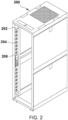
- FIG. 2 illustrates a rack 200 configured to house one or more pieces of equipment such as data center equipment.
- the rack 200 houses a rack PDU 202 including a plurality of electrical outlets 204.
- the rack PDU 202 may be configured according to one or more aspects disclosed herein.
- the rack PDU 202 may include a measurement system 206 for measuring currents for one or more outputs 204.
- the rack PDU 202 may include the system 100 of FIG. 1 .
- the microcontroller 102 in the embodiment of FIG. 1 may be included in the measurement system 206 and may have one or more input and output channels, each being associated with a respective output 204 of the rack PDU 202.
- the current through each outlet 204 may be measured independently over a period of time with measurement values being stored in the output current readings 132.
- FIG. 3 illustrates one example measurement process 300 executed by the system 100.
- the measurement process 300 begins in act 302.
- the system 100 performs an initialization routine.
- the initialization routine includes configuring a timer which is utilized by the processes of FIGs. 4 , 6 and 7 to determine a zero crossing of a voltage waveform for an AC power source as described below.
- the timer may be configured with a set of pre-defined parameters.
- the pre-defined parameters may include a counter mode (e.g., count-up or count-down), a clock source, and a pre-scale value.
- a 16-bit timer may utilize a 10 MHz clock source and be configured with a 1/8 pre-scale value.
- the 16-bit timer provides a high resolution count of the time intervals over one full line cycle (at 50 or 60 Hz) of outlet current.
- the system 100 uses the microcontroller 102 to determine the power line frequency.
- the microcontroller 102 monitors AC power at the input line 128 to determine a zero-crossing and an offset from the zero-crossing for each current reading sampled at an output.
- the initialization routine zeros out the output current readings 132.
- the output current readings 132 may be configured as a two-dimensional array.
- the first dimension may be configured as an integer value which represents a particular output.
- output 110 FIG. 1
- outputs 112-120 may be represented by an index value of 1-5, etc.
- the second dimension of the two-dimensional array may be configured with a plurality of value pairs comprising an output current measurement reading and a binary status flag.
- the second dimension of the two-dimensional array may be configured with a plurality of values comprising only the output current measurement readings. As discussed further below with reference to FIG.
- each output current is stored in the output current readings 132 ( FIG. 1 ) using a number format which enables the root mean square (RMS) current to be efficiently computed for the input of the PDU during the processes shown in FIGS. 6 and 7 .
- RMS root mean square
- the system 100 executes an AC voltage zero-crossing subroutine to determine the power line frequency (e.g., 50 or 60 Hz).
- the system 100 starts the timer initialized in act 304 in a count-up mode from an initial value. Subsequent rising edge zero-crossings may result in the re-initialization of the timer, which in turns causes the timer to count up from an initial value.
- the initial value of the timer may be used as a reference to determine if zero crossings have been missed and an overflow condition has occurred.
- the system 100 may determine a zero-crossing has been missed and an overflow condition has occurred.
- the system 100 uses the microcontroller 102 to determine the power line frequency and zero-crossing for AC power at an input, such as the input line 128 of FIG. 1 .
- each current sampled from an output e.g., outputs 112-120 of FIG. 1
- a plurality of current measurements sampled across each output may be aligned (e.g., time-shifted) so that current measurements across each of the outputs lineup at the zero crossing. Accordingly, subsequent calculations during act 310, as discussed further below, may determine an RMS output current value regardless of whether output currents are out of phase (e.g., due to non-linear loading).
- the system 100 executes an output current measurement subroutine periodically.
- instantaneous current measurements from each of the outputs 110-120 are collected (e.g., via the CT 134).
- the period of time between executions of the output current measurement subroutine may be determined by the use of the timer initialized in act 304. In other embodiments, a different timer may be used. In one example, a period is configured such that each output current is measured (or sampled) often enough to capture a complete set of measurements representing an output waveform by associating samples within the output current readings 132 with time intervals.
- time buckets The time intervals may be referred to herein as "time buckets.”
- the number of time buckets may be based on the microcontroller 102 determining a power line frequency.
- the system 100 executes a subroutine to determine an input RMS current.
- the subroutine may be executed at an interval which is longer than the period of the output current measurement subroutine of act 308 (e.g., to insure that all of the outputs have been sampled and have values within the time buckets).
- the subroutine is executed one time per second.
- the subroutine may determine if the output current readings 132 have a complete set of measurements prior to calculating a root mean square (RMS) current value for the input of the PDU.
- RMS root mean square
- Acts 306-310 of the measurement process 200 may be executed continuously throughout the operation of the system 100, or until a command is executed by the system 100 to suspend execution.
- the measurement process 200 ends in act 310.
- FIG. 4 One example of an output current measurement subroutine 400 is illustrated in FIG. 4 .
- an instantaneous current from each of the outputs 110-120 is sampled by the microcontroller 102 ( FIG. 1 ).
- the microcontroller 102 determines a current reading using a CT 134 coupled to an output.
- each output current reading is stored in memory using a number format which is used during subsequent computations to determine an input RMS current value.
- the current reading may be converted prior to storing the current reading in memory.
- the current reading may be converted to tenths of an amp, hundredths of an amp, etc.
- the current reading may be a data type such as a signed integer or floating point number.
- the output current measurement may be a signed number to preserve the phase relationship needed when executing the subroutines of FIGS. 6 and 7 .
- a timer value is retrieved from the timer initialized in act 304 of FIG. 3 .
- the timer is re-initialized and begins to count up from an initial value.
- the initial value is compared against a retrieved timer value.
- a timer value which is greater than the initial value is an indication that the timer has not rolled over, and thus, valid measurements may be performed on an output.
- the timer value is converted into an array index.
- the array index is computed based on the upper bits (i.e., most-significant bits) of the timer value.
- the array index is a "time bucket" which is used to store an output current measurement.
- a 16-bit timer may be divided by 1024 (e.g., 1/8 prescale) to form 64 discrete time buckets for storage of output current measurements. After a zero-crossing is detected, each measurement will correspond to a unique time bucket based on the index determined in the act 408.
- the unique time-buckets are used advantageously to sum current measurements across each output based on a sequence of time-buckets.
- the use of a timer is optional in acts 406 and 408.
- the system 100 may use the microcontroller 102 coupled to an input, such as input 128 of FIG. 1 , to obtain an array index (i.e., an offset from a zero-crossing) for an output current measurement.
- an array index i.e., an offset from a zero-crossing
- a zero-crossing index may be stored in the memory 130 ( FIG. 1 ).
- the zero-crossing index may be used to determine which current measurement index in the output current readings 132 corresponds to the zero-crossing.
- Subsequent processes such as the sub-routine 600 of FIG. 6 discussed further below, may utilize each zero-crossing index to align (e.g., time-shift) current measurements across a plurality of outputs.
- the current readings which were sampled in act 404 may be stored in the memory 130 of the microcontroller 102.
- the output current readings 132 may be stored in a two-dimensional array which is indexed based on individual outputs. Each output of the two-dimensional array is associated with N number of time buckets (e.g., 64) as determined by the initialization routine of act 304 ( FIG. 3 ).
- the output current measurement is stored within the output current readings 132.
- the stored measurement may be configured as a data type which is signed (e.g., signed integer, floating point decimal) in order to preserve the phase relationship for subsequent RMS computations.
- signed e.g., signed integer, floating point decimal
- a status flag may be set for the current reading acquired in act 404 and stored as a pair with the current reading in the output current readings 132.
- the status flag may be configured as a binary value.
- a binary value of "0" may represent a constant defined as NO_READING, and a binary value of "1" may represent a constant defined as OK_READING.
- the status flags may be used to determine if a complete set of measurements representing the entirety of a input current waveform of a PDU is stored within the output current readings 132 prior to performing an RMS computation process, such as the RMS computation process of FIG. 7 .
- the current reading is stored in the output current readings 132 without a status flag.
- act 414 the system 100 determines if all of the outputs have been sampled over one full line cycle.
- the output measurement subroutine 400 returns to act 404 and performs acts 406-412 until each output (e.g., outputs 110-120 of FIG. 1 ) has been sampled and is represented by a complete set of measurements in the output current readings 132.
- a "leaky average” technique may be utilized to smooth out current readings within the output measurement values 132. For example, a portion of the measurement values (e.g., 1/8 of the measurements) within the output measurement values 132 may be averaged with a portion of previously measured current values (e.g., 7/8 of the previously measured current values).
- the system 100 may store a copy of the previously sampled output measurement values for purpose of mitigating the impact of low-level noise within the sampled AC signal.
- the output current measurement subroutine 400 ends at act 416.
- the time buckets 504 may be used by the processes of FIGS. 6 and 7 to compute an input RMS current value.
- each time bucket 504 may be a unique value based on a timer counting up upon detection of the zero-crossing of a source signal.
- the upper bits (or most-significant bits) of a 16-bit timer may be used to define each time bucket.
- a 16-bit timer with a 10 MHz may be divided by 1024 (i.e., a 1/8 prescale) enabling 64 time buckets for storing a representation of an input current waveform of a PDU.
- a higher or lower frequency clock may be used to sample output current measurements.
- each time bucket 504 may be a unique value based on the microcontroller 102 determining a power line frequency.
- the embodiment shown illustrates the tabular view 500 having three time buckets, other embodiments may include any number of time buckets based on the frequency of an AC power source determined in act 306 of FIG. 3 .
- the status flag 510 indicates that a particular measurement has been performed for an output for a given time bucket.
- the initialization routine zeros out the memory area in which the output current readings 132 are stored.
- a value other than zero such as a binary one, may indicate to the processes of FIGS. 6 and 7 that a complete set of measurements is available for all outputs across all time buckets, such as the outputs 110-120 of FIG. 1 .
- the system 100 checks the status flag for each of the output measurement values stored within the output current readings 132. If any status flag is not set (e.g., NO_READ) then the subroutine exits in act 622 and returns to an output sampling subroutine, such as the output current measurement subroutine 400 of FIG. 4 . If all status flags are set (e.g., all are OK_READING) then the sub-routine 600 continues to act 608.
- acts 606, 608 and 610 are optional. For instance, memory may be saved by not including a status flag. In this embodiment, the process continues directly from act 602 to act 608.
- a loop is configured with counters (I) and (J), representing outputs and time buckets, respectively.
- a loop is executed wherein each measurement value corresponding to a time bucket (J) is summed.
- current measurements in the output current readings 132 are aligned (time-shifted) based on a zero-crossing index of each output prior to summing.
- output current readings are illustrated in the tabular view 500.
- summation in accordance with acts 610-614 would include summing an entire row (e.g., the row corresponding to time bucket zero) of measurement values for a particular time bucket 504 across all outputs.
- the summation of the time bucket (J) is stored in a bank array. The summation may be indexed in the bank array based on the time bucket.
- counter (J) is incremented and the loop continues until all of the output measurement values have been summed (e.g., (J) is equal to the number of outputs). If all of the output measurement values have been summed for a particular time bucket and stored in the bank array, the loop exits at act 616.
- the time bucket counter (I) is incremented.
- counter (I) is equal to the number of time buckets the subroutine continues to act 626.
- a loop is initialized.
- the bank array may be configured as a single-dimensional array which is indexed by time bucket values. In this way, the entirety of an input current waveform of a PDU may be represented by summed measurement values in each sequential time bucket of the bank array.
- each element of the bank array is squared to result in a positive square value.
- the resulting positive square value may then be stored in a square result array.
- the square result array is a single-dimension array with a number of elements corresponding to a number of time buckets (e.g., 64).
- a counter is incremented.
- act 712 if it is determined that the counter value is equal to the number of time buckets, the subroutine 700 continues to act 714. If the counter value is not equal to the number of time buckets, the subroutine 700 continues to perform acts 706-712 until all values within the bank array have been squared (i.e., all time buckets have a positive value).
- the RMS value of the sum square array is determined.
- the resulting value may be converted to present the input RMS current for display, such as via a display device of the measurement unit 206 ( FIG. 2 ).
- the resulting value may be mathematically converted to tenths of amps, hundredths of amps, etc.
- Processes 300, 400, 600 and 700 each depict one particular sequence of acts in a particular embodiment. Some acts are optional and, as such, may be omitted in accord with one or more embodiments. Additionally, the order of the acts can be altered, or other acts can be added, without departing from the scope of the embodiments described herein.
- One or more features disclosed herein may be implemented in one or more PDUs or rack PDUs. In other embodiments, various aspects and functions described herein may be implemented in one or more apparatuses separate from a PDU or a rack PDU. An apparatus configured according to one or more features disclosed herein may be configured to couple to a PDU or a rack PDU to allow measurement of dynamic signals.
- FIG. 8 there is illustrated a block diagram of one example of computing components forming a system 800 which may be configured to implement one or more aspects disclosed herein.
- the system 800 may be configured to implement the measurement system 100 as illustrated and described above with reference to FIG. 1 .
- the system 800 may include for example a general-purpose computing platform such as those based on Intel PENTIUM-type processor, Motorola PowerPC, Sun UltraSPARC, Hewlett-Packard PA-RISC processors, or any other type of processor.
- System 800 may include specially-programmed, special-purpose hardware, for example, an application-specific integrated circuit (ASIC).
- ASIC application-specific integrated circuit
- Various aspects of the present disclosure may be implemented as specialized software executing on the system 800 such as that shown in FIG. 8 .
- the system 800 may include a processor/ASIC 806 connected to one or more memory devices 810, such as a disk drive, memory, flash memory or other device for storing data.
- Memory 810 may be used for storing programs and data during operation of the system 800.
- Components of the computer system 800 may be coupled by an interconnection mechanism 808, which may include one or more buses (e.g., between components that are integrated within a same machine) and/or a network (e.g., between components that reside on separate machines).
- the interconnection mechanism 808 enables communications (e.g., data, instructions) to be exchanged between components of the system 800. Further, in some embodiments the interconnection mechanism 808 may be disconnected during servicing of a PDU.
- the system 800 also includes one or more input devices 804, which may include for example, a keyboard or a touch screen. An input device may be used for example to configure the measurement system or to provide input parameters.
- the system 800 includes one or more output devices 802, which may include for example a display.
- the computer system 800 may contain one or more interfaces (not shown) that may connect the computer system 800 to a communication network, in addition or as an alternative to the interconnection mechanism 808.
- the system 800 may include a storage system 812, which may include a computer readable and/or writeable nonvolatile medium in which signals may be stored to provide a program to be executed by the processor or to provide information stored on or in the medium to be processed by the program.
- the medium may, for example, be a disk or flash memory and in some examples may include RAM or other non-volatile memory such as EEPROM.
- the processor may cause data to be read from the nonvolatile medium into another memory 810 that allows for faster access to the information by the processor/ASIC than does the medium.
- This memory 810 may be a volatile, random access memory such as a dynamic random access memory (DRAM) or static memory (SRAM). It may be located in storage system 812 or in memory system 810.
- DRAM dynamic random access memory
- SRAM static memory
- the processor 806 may manipulate the data within the integrated circuit memory 810 and then copy the data to the storage 812 after processing is completed.
- a variety of mechanisms are known for managing data movement between storage 812 and the integrated circuit memory element 810, and the disclosure is not limited thereto. The disclosure is not limited to a particular memory system 810 or a storage system 812.
- the system 800 may include a general-purpose computer platform that is programmable using a high-level computer programming language.
- the system 800 may be also implemented using specially programmed, special purpose hardware, e.g. an ASIC.
- the system 800 may include a processor 806, which may be a commercially available processor such as the well-known Pentium class processor available from the Intel Corporation. Many other processors are available.
- the processor 806 may execute an operating system which may be, for example, a Windows operating system available from the Microsoft Corporation, MAC OS System X available from Apple Computer, the Solaris Operating System available from Sun Microsystems, or UNIX and/or LINUX available from various sources. Many other operating systems may be used.
- the processor and operating system together may form a computer platform for which application programs in high-level programming languages may be written. It should be understood that the disclosure is not limited to a particular computer system platform, processor, operating system, or network. Also, it should be apparent to those skilled in the art that the present disclosure is not limited to a specific programming language or computer system. Further, it should be appreciated that other appropriate programming languages and other appropriate computer systems could also be used.
Landscapes
- Engineering & Computer Science (AREA)
- Physics & Mathematics (AREA)
- General Physics & Mathematics (AREA)
- Theoretical Computer Science (AREA)
- Power Engineering (AREA)
- General Engineering & Computer Science (AREA)
- Measurement Of Current Or Voltage (AREA)
Claims (16)
- Eine Stromverteilungseinheit (PDU) (100), die Folgendes beinhaltet:einen Eingang (128), der konfiguriert ist, um Eingangsleistung aufzunehmen;eine Vielzahl von Ausgängen (110, 112, 114, 116, 118, 120), von denen jeder an den Eingang gekoppelt ist und konfiguriert ist, um Eingangsleistung aufzunehmen, und jeder Ausgang der Vielzahl von Ausgängen einen Ausgang aufweist, der konfiguriert ist, um Ausgangsleistung bereitzustellen;eine Vielzahl von Ausgangsstromsensoren (134), wobei jeder Ausgangsstromsensor der Vielzahl von Ausgangsstromsensoren an einen entsprechenden Ausgang der Vielzahl von Ausgängen gekoppelt ist und konfiguriert ist, um Ausgangsstrom zu detektieren, der durch den entsprechenden Ausgang bereitgestellt wird; undeine Steuerung (102), die an die Vielzahl von Ausgangsstromsensoren gekoppelt ist und für Folgendes konfiguriert ist:Bestimmen einer Vielzahl von Zeitintervallen basierend auf einer Frequenz der Eingangsleistung;Aufnehmen, von jedem Ausgangsstromsensor der Vielzahl von Ausgangsstromsensoren, eines Stromwerts an jedem Zeitintervall der Vielzahl von Zeitintervallen für jeden Ausgang der Vielzahl von Ausgängen;Erzeugen einer Vielzahl von Strommesssummen, wobei jede Strommesssumme der Vielzahl von Strommessummen auf den aufgenommenen Stromwerten basiert, die mit einem entsprechenden Zeitintervall der Vielzahl von Zeitintervallen assoziiert sind;Bestimmen eines quadratischen Mittelwerts (RMS-Wert) basierend auf der Vielzahl von Strommesssummen, undBestimmen, basierend auf dem RMS-Wert, eines RMS-Stromwerts der Eingangsleistung.
- PDU gemäß Anspruch 1, wobei die PDU ferner einen ersten Zeitgeber beinhaltet, der an die Steuerung gekoppelt ist, und wobei die Steuerung ferner für Folgendes konfiguriert ist:Rücksetzen des ersten Zeitgebers reagierend auf Detektion eines Nulldurchgangs einer Wellenform der Eingangsleistung; undBestimmen der Frequenz der Eingangsleistung basierend auf einem Wert des ersten Zeitgebers.
- PDU gemäß Anspruch 2, wobei die Steuerung ferner konfiguriert ist, um den aufgenommenen Stromwert mit einem Zeitintervall der Vielzahl von Zeitintervallen zu assoziieren, wobei das Zeitintervall basierend auf einem skalierten Wert des ersten Zeitgebers bestimmt wird.
- PDU gemäß Anspruch 1, wobei die Steuerung ferner konfiguriert ist, um mindestens eine Strommessung der Vielzahl von Strommesssummen mit mindestens einer vorherigen Strommessung unter Verwendung einer schlecht isolierten Mittlungstechnik zu mitteln.
- PDU gemäß Anspruch 1, wobei die PDU ferner einen Speicher (130) beinhaltet, und wobei die Steuerung ferner konfiguriert ist, um die Vielzahl von Strommesssummen in dem Speicher in einer zweidimensionalen Anordnung zu speichern, wobei eine erste Dimension der zweidimensionalen Anordnung ein Index ist, der einer Vielzahl von Ausgangswerten entspricht, und wobei eine zweite Dimension der zweidimensionalen Anordnung der Vielzahl von Zeitintervallen entspricht.
- PDU gemäß Anspruch 5, wobei jedes Zeitintervall der Vielzahl von Zeitintervallen ein Messwertpaar umfasst, wobei das Messungswertpaar einen Messungswert und ein Statusflag umfasst.
- PDU gemäß Anspruch 6, wobei das Statusflag konfiguriert ist, um anzuzeigen, ob eine Messung abgetastet worden ist, und wobei die Steuerung ferner für Folgendes konfiguriert ist:
Bestimmen, dass basierend auf einem Status jedes Statusflag ein kompletter Satz von Messwerten in der zweidimensionalen Anordnung verfügbar ist. - PDU gemäß Anspruch 7, wobei jede Strommesssumme der Vielzahl von Strommessummen auf der Summierung eines Messwerts basiert, der jedem Ausgang der Vielzahl von Ausgängen an einem Zeitintervall entspricht.
- PDU gemäß Anspruch 7, wobei sich der RMS-Wert basierend auf dem Durchführen einer RMS-Berechnung unter Verwendung der Vielzahl von Strommesssummen einem Stromwert für den Eingang nähert.
- PDU gemäß Anspruch 9, wobei die Steuerung ferner konfiguriert ist, um den RMS-Wert anzuzeigen.
- Ein Verfahren zum Bestimmen eines quadratischen Mittelwerts (RMS) für einen Eingang einer Stromverteilungseinheit (PDU) (100) mit einer Vielzahl von Ausgangsstromsensoren (134), von denen jeder mit einem entsprechenden Ausgang (110, 112, 114, 116, 118, 120) einer Vielzahl von Ausgängen gekoppelt ist, wobei das Verfahren Folgendes beinhaltet:Bestimmen einer Vielzahl von Zeitintervallen basierend auf einer Frequenz einer Eingangsleistung, die dem Eingang bereitgestellt wird;Messen eines Strommesswerts an jedem Zeitintervall der Vielzahl von Zeitintervallen für jeden Ausgang der Vielzahl von Ausgängen;Erzeugen einer Vielzahl von Strommesssummen, wobei jede Strommesssumme der Vielzahl von Strommessummen auf den Strommesswerten basiert, die mit einem entsprechenden Zeitintervall der Vielzahl von Zeitintervallen assoziiert sind;Bestimmen eines quadratischen Mittelwerts (RMS) basierend auf der Vielzahl von Strommesssummen, undBestimmen, basierend auf dem RMS-Wert, eines RMS-Stromwerts der Eingangsleistung.
- Verfahren gemäß Anspruch 11, das ferner Folgendes beinhaltet:Rücksetzen des ersten Zeitgebers reagierend auf Detektion eines Nulldurchgangs einer Wellenform der Eingangsleistung; undBestimmen der Frequenz der Eingangsleistung basierend auf einem Wert des ersten Zeitgebers.
- Verfahren gemäß Anspruch 12, wobei das Verfahren ferner das Assoziieren des Strommesswerts für jeden Ausgang der Vielzahl von Ausgängen mit einem Zeitintervall der Vielzahl von Zeitintervallen beinhaltet, wobei das Zeitintervall basierend auf einem skalierten Wert des ersten Zeitgebers bestimmt wird.
- Verfahren gemäß Anspruch 13, wobei das Messen eines Stroms an jedem Zeitintervall der Vielzahl von Zeitintervallen für jeden Ausgang der Vielzahl von Ausgängen ferner das Messen jedes Ausgangs der Vielzahl von Ausgängen auf eine sequentielle Weise umfasst.
- Verfahren gemäß Anspruch 14, wobei das Bestimmen des quadratischen Mittelwerts (RMS) basierend auf der Vielzahl von Strommesssummen ferner das Summieren eines Messwerts, der jedem Ausgang der Vielzahl von Ausgängen zu jedem Zeitinttervall der Vielzahl von Zeitintervallen entspricht, um die Vielzahl von Strommesssummen zu erlangen, und Durchführen einer RMS-Berechnung auf der Vielzahl von Strommesssummen umfasst, um sich dem RMS-Wert für den Eingang zu nähern.
- Ein Computerprogramm, das Anweisungen beinhaltet, die, wenn das Programm durch die Steuerung (102) gemäß einem der Ansprüche 1 bis 10 ausgeführt wird, bewirken, dass die Steuerung (102) das Verfahren gemäß einem der Ansprüche 11 bis 15 ausführt.
Applications Claiming Priority (1)
| Application Number | Priority Date | Filing Date | Title |
|---|---|---|---|
| PCT/US2013/077771 WO2015099726A1 (en) | 2013-12-26 | 2013-12-26 | Systems and methods for determining input current of a power distribution unit |
Publications (4)
| Publication Number | Publication Date |
|---|---|
| EP3087451A1 EP3087451A1 (de) | 2016-11-02 |
| EP3087451A4 EP3087451A4 (de) | 2017-11-01 |
| EP3087451B1 true EP3087451B1 (de) | 2025-04-09 |
| EP3087451C0 EP3087451C0 (de) | 2025-04-09 |
Family
ID=53479392
Family Applications (1)
| Application Number | Title | Priority Date | Filing Date |
|---|---|---|---|
| EP13900211.7A Active EP3087451B1 (de) | 2013-12-26 | 2013-12-26 | Systeme und verfahren zur bestimmung des eingangsstroms einer stromverteilereinheit |
Country Status (3)
| Country | Link |
|---|---|
| US (1) | US10877077B2 (de) |
| EP (1) | EP3087451B1 (de) |
| WO (1) | WO2015099726A1 (de) |
Families Citing this family (5)
| Publication number | Priority date | Publication date | Assignee | Title |
|---|---|---|---|---|
| US10250032B2 (en) | 2015-04-24 | 2019-04-02 | Vertiv Corporation | Intelligent power strip with management of bistable relays to reduce current in-rush |
| CN108110999B (zh) * | 2016-11-23 | 2020-10-16 | 台达电子工业股份有限公司 | 配电装置及其操作方法 |
| WO2018129340A1 (en) * | 2017-01-06 | 2018-07-12 | Liebert Corporation | System and method of identifying path of residual current flow through an intelligent power strip |
| JP2023177687A (ja) * | 2022-06-02 | 2023-12-14 | 株式会社アドバンテスト | ヒータ駆動制御装置、電子部品ハンドリング装置、電子部品試験装置、及び、ヒータ駆動制御方法 |
| US20260093590A1 (en) * | 2024-09-27 | 2026-04-02 | Kyndryl, Inc. | Safety compliance for maintenance and operations of critical systems |
Family Cites Families (9)
| Publication number | Priority date | Publication date | Assignee | Title |
|---|---|---|---|---|
| US5422567A (en) * | 1993-12-27 | 1995-06-06 | Valleylab Inc. | High frequency power measurement |
| US6191676B1 (en) * | 1994-10-21 | 2001-02-20 | Spinel Llc | Apparatus for suppressing nonlinear current drawing characteristics |
| US7171461B2 (en) * | 1996-07-23 | 2007-01-30 | Server Technology, Inc. | Network remote power management outlet strip |
| US7741853B2 (en) * | 2007-09-28 | 2010-06-22 | Rockwell Automation Technologies, Inc. | Differential-mode-current-sensing method and apparatus |
| WO2009086485A1 (en) * | 2007-12-28 | 2009-07-09 | Server Technology, Inc. | Power distribution, management, and monitoring systems and methods |
| CA2766807A1 (en) | 2009-06-25 | 2010-12-29 | Server Technology, Inc. | Power distribution apparatus with input and output power sensing and method of use |
| EP2429060B1 (de) * | 2010-09-09 | 2014-05-14 | Racktivity NV | Stromverteilungseinheit mit Oszilloskop-Funktion |
| US8949053B2 (en) * | 2011-07-29 | 2015-02-03 | Schneider Electric It Corporation | Systems and methods for current and voltage monitoring |
| CN104350388B (zh) * | 2012-04-12 | 2017-06-20 | 施耐德电气It公司 | 用于检测支路电流的系统和方法 |
-
2013
- 2013-12-26 US US15/108,016 patent/US10877077B2/en active Active
- 2013-12-26 WO PCT/US2013/077771 patent/WO2015099726A1/en not_active Ceased
- 2013-12-26 EP EP13900211.7A patent/EP3087451B1/de active Active
Also Published As
| Publication number | Publication date |
|---|---|
| WO2015099726A1 (en) | 2015-07-02 |
| EP3087451A1 (de) | 2016-11-02 |
| US20160327595A1 (en) | 2016-11-10 |
| US10877077B2 (en) | 2020-12-29 |
| EP3087451A4 (de) | 2017-11-01 |
| EP3087451C0 (de) | 2025-04-09 |
Similar Documents
| Publication | Publication Date | Title |
|---|---|---|
| US9625503B2 (en) | Method and device for analysing the quality of the electrical energy in a three-phase electric network | |
| US10877077B2 (en) | Systems and methods for determining input current of a power distribution unit | |
| Rakpenthai et al. | On harmonic state estimation of power system with uncertain network parameters | |
| RU2240567C2 (ru) | Способ и система измерения зависящих от частоты электрических параметров | |
| US8868364B2 (en) | Apparatus and method for real time harmonic spectral analyzer | |
| Hill et al. | Design of a microprocessor-based digital wattmeter | |
| US7398168B2 (en) | Method and system for monitoring power flow through an electric power transmission line | |
| CN104931775A (zh) | 一种具有电能质量分析功能的网络多功能三相电能表 | |
| KR20190076794A (ko) | 계기용 변압변류기(mof)의 전류오차 측정장치 | |
| US11650241B1 (en) | Incremental quantities-based fault locating technique and system | |
| CN114879125A (zh) | 三相电能表计量方法、三相电能表及可读存储介质 | |
| Moustafa et al. | A smart web-based power quality and energy monitoring system with enhanced features | |
| CN117630475A (zh) | 三相四线电能表的等效视在功率实现方法、装置及设备 | |
| Gaunt et al. | True power factor metering for m-wire systems with distortion, unbalance and direct current components | |
| US20220283209A1 (en) | Signal analysis method, and apparatus for three-phase system, and program | |
| Sadinezhad et al. | Slow sampling on-line harmonics/interharmonics estimation technique for smart meters | |
| CN115047233A (zh) | 母线电流的非接触测量方法、装置、电子设备和存储介质 | |
| Repak et al. | Design of power quality analyzer | |
| Rodrigues et al. | Holomorphic Embedding State Estimation Method using Phasor Measurement Units | |
| US3727132A (en) | Method of and system for measuring electrical powers in an energetic deformant state | |
| CN202770886U (zh) | 电量追补设备 | |
| JP7215226B2 (ja) | 接続相推定装置、接続相推定プログラム及び接続相推定方法 | |
| KR102107228B1 (ko) | 전력 계측 시스템 | |
| RU2569939C1 (ru) | Способ определения угла сдвига фаз между двумя синусоидальными сигналами (варианты) | |
| Guamán et al. | Design of a Low-Cost Phasor Measurement Unit (PMU) for Three-Phase Distribution Power Systems according IEEE C37. 118.1 |
Legal Events
| Date | Code | Title | Description |
|---|---|---|---|
| PUAI | Public reference made under article 153(3) epc to a published international application that has entered the european phase |
Free format text: ORIGINAL CODE: 0009012 |
|
| 17P | Request for examination filed |
Effective date: 20160630 |
|
| AK | Designated contracting states |
Kind code of ref document: A1 Designated state(s): AL AT BE BG CH CY CZ DE DK EE ES FI FR GB GR HR HU IE IS IT LI LT LU LV MC MK MT NL NO PL PT RO RS SE SI SK SM TR |
|
| AX | Request for extension of the european patent |
Extension state: BA ME |
|
| DAX | Request for extension of the european patent (deleted) | ||
| A4 | Supplementary search report drawn up and despatched |
Effective date: 20171002 |
|
| RIC1 | Information provided on ipc code assigned before grant |
Ipc: G01R 21/133 20060101AFI20170926BHEP Ipc: G01R 19/10 20060101ALI20170926BHEP Ipc: G01R 19/02 20060101ALI20170926BHEP Ipc: G06F 1/28 20060101ALI20170926BHEP Ipc: G06F 1/26 20060101ALI20170926BHEP |
|
| STAA | Information on the status of an ep patent application or granted ep patent |
Free format text: STATUS: EXAMINATION IS IN PROGRESS |
|
| 17Q | First examination report despatched |
Effective date: 20201113 |
|
| GRAP | Despatch of communication of intention to grant a patent |
Free format text: ORIGINAL CODE: EPIDOSNIGR1 |
|
| STAA | Information on the status of an ep patent application or granted ep patent |
Free format text: STATUS: GRANT OF PATENT IS INTENDED |
|
| INTG | Intention to grant announced |
Effective date: 20240826 |
|
| GRAJ | Information related to disapproval of communication of intention to grant by the applicant or resumption of examination proceedings by the epo deleted |
Free format text: ORIGINAL CODE: EPIDOSDIGR1 |
|
| STAA | Information on the status of an ep patent application or granted ep patent |
Free format text: STATUS: EXAMINATION IS IN PROGRESS |
|
| GRAP | Despatch of communication of intention to grant a patent |
Free format text: ORIGINAL CODE: EPIDOSNIGR1 |
|
| STAA | Information on the status of an ep patent application or granted ep patent |
Free format text: STATUS: GRANT OF PATENT IS INTENDED |
|
| INTC | Intention to grant announced (deleted) | ||
| RAP3 | Party data changed (applicant data changed or rights of an application transferred) |
Owner name: SCHNEIDER ELECTRIC IT CORPORATION |
|
| INTG | Intention to grant announced |
Effective date: 20241118 |
|
| GRAS | Grant fee paid |
Free format text: ORIGINAL CODE: EPIDOSNIGR3 |
|
| GRAA | (expected) grant |
Free format text: ORIGINAL CODE: 0009210 |
|
| STAA | Information on the status of an ep patent application or granted ep patent |
Free format text: STATUS: THE PATENT HAS BEEN GRANTED |
|
| AK | Designated contracting states |
Kind code of ref document: B1 Designated state(s): AL AT BE BG CH CY CZ DE DK EE ES FI FR GB GR HR HU IE IS IT LI LT LU LV MC MK MT NL NO PL PT RO RS SE SI SK SM TR |
|
| REG | Reference to a national code |
Ref country code: GB Ref legal event code: FG4D |
|
| REG | Reference to a national code |
Ref country code: CH Ref legal event code: EP |
|
| REG | Reference to a national code |
Ref country code: IE Ref legal event code: FG4D |
|
| U01 | Request for unitary effect filed |
Effective date: 20250409 |
|
| U07 | Unitary effect registered |
Designated state(s): AT BE BG DE DK EE FI FR IT LT LU LV MT NL PT RO SE SI Effective date: 20250415 |
|
| PG25 | Lapsed in a contracting state [announced via postgrant information from national office to epo] |
Ref country code: ES Free format text: LAPSE BECAUSE OF FAILURE TO SUBMIT A TRANSLATION OF THE DESCRIPTION OR TO PAY THE FEE WITHIN THE PRESCRIBED TIME-LIMIT Effective date: 20250409 |
|
| PG25 | Lapsed in a contracting state [announced via postgrant information from national office to epo] |
Ref country code: GR Free format text: LAPSE BECAUSE OF FAILURE TO SUBMIT A TRANSLATION OF THE DESCRIPTION OR TO PAY THE FEE WITHIN THE PRESCRIBED TIME-LIMIT Effective date: 20250710 Ref country code: NO Free format text: LAPSE BECAUSE OF FAILURE TO SUBMIT A TRANSLATION OF THE DESCRIPTION OR TO PAY THE FEE WITHIN THE PRESCRIBED TIME-LIMIT Effective date: 20250709 |
|
| PG25 | Lapsed in a contracting state [announced via postgrant information from national office to epo] |
Ref country code: PL Free format text: LAPSE BECAUSE OF FAILURE TO SUBMIT A TRANSLATION OF THE DESCRIPTION OR TO PAY THE FEE WITHIN THE PRESCRIBED TIME-LIMIT Effective date: 20250409 |
|
| PG25 | Lapsed in a contracting state [announced via postgrant information from national office to epo] |
Ref country code: HR Free format text: LAPSE BECAUSE OF FAILURE TO SUBMIT A TRANSLATION OF THE DESCRIPTION OR TO PAY THE FEE WITHIN THE PRESCRIBED TIME-LIMIT Effective date: 20250409 |
|
| PG25 | Lapsed in a contracting state [announced via postgrant information from national office to epo] |
Ref country code: RS Free format text: LAPSE BECAUSE OF FAILURE TO SUBMIT A TRANSLATION OF THE DESCRIPTION OR TO PAY THE FEE WITHIN THE PRESCRIBED TIME-LIMIT Effective date: 20250709 |
|
| PG25 | Lapsed in a contracting state [announced via postgrant information from national office to epo] |
Ref country code: IS Free format text: LAPSE BECAUSE OF FAILURE TO SUBMIT A TRANSLATION OF THE DESCRIPTION OR TO PAY THE FEE WITHIN THE PRESCRIBED TIME-LIMIT Effective date: 20250809 |
|
| PGFP | Annual fee paid to national office [announced via postgrant information from national office to epo] |
Ref country code: GB Payment date: 20251223 Year of fee payment: 13 |
|
| PG25 | Lapsed in a contracting state [announced via postgrant information from national office to epo] |
Ref country code: SM Free format text: LAPSE BECAUSE OF FAILURE TO SUBMIT A TRANSLATION OF THE DESCRIPTION OR TO PAY THE FEE WITHIN THE PRESCRIBED TIME-LIMIT Effective date: 20250409 |
|
| PG25 | Lapsed in a contracting state [announced via postgrant information from national office to epo] |
Ref country code: CZ Free format text: LAPSE BECAUSE OF FAILURE TO SUBMIT A TRANSLATION OF THE DESCRIPTION OR TO PAY THE FEE WITHIN THE PRESCRIBED TIME-LIMIT Effective date: 20250409 |
|
| PG25 | Lapsed in a contracting state [announced via postgrant information from national office to epo] |
Ref country code: SK Free format text: LAPSE BECAUSE OF FAILURE TO SUBMIT A TRANSLATION OF THE DESCRIPTION OR TO PAY THE FEE WITHIN THE PRESCRIBED TIME-LIMIT Effective date: 20250409 |
|
| U20 | Renewal fee for the european patent with unitary effect paid |
Year of fee payment: 13 Effective date: 20251223 |
|
| PLBE | No opposition filed within time limit |
Free format text: ORIGINAL CODE: 0009261 |
|
| STAA | Information on the status of an ep patent application or granted ep patent |
Free format text: STATUS: NO OPPOSITION FILED WITHIN TIME LIMIT |
|
| REG | Reference to a national code |
Ref country code: CH Ref legal event code: L10 Free format text: ST27 STATUS EVENT CODE: U-0-0-L10-L00 (AS PROVIDED BY THE NATIONAL OFFICE) Effective date: 20260218 |
|
| 26N | No opposition filed |
Effective date: 20260112 |