EP3087449B1 - Rotational to translational locking hinge - Google Patents
Rotational to translational locking hinge Download PDFInfo
- Publication number
- EP3087449B1 EP3087449B1 EP14874271.1A EP14874271A EP3087449B1 EP 3087449 B1 EP3087449 B1 EP 3087449B1 EP 14874271 A EP14874271 A EP 14874271A EP 3087449 B1 EP3087449 B1 EP 3087449B1
- Authority
- EP
- European Patent Office
- Prior art keywords
- locking
- sliding component
- component
- shaft
- hinge
- Prior art date
- Legal status (The legal status is an assumption and is not a legal conclusion. Google has not performed a legal analysis and makes no representation as to the accuracy of the status listed.)
- Active
Links
Images




Classifications
-
- E—FIXED CONSTRUCTIONS
- E05—LOCKS; KEYS; WINDOW OR DOOR FITTINGS; SAFES
- E05D—HINGES OR SUSPENSION DEVICES FOR DOORS, WINDOWS OR WINGS
- E05D11/00—Additional features or accessories of hinges
- E05D11/10—Devices for preventing movement between relatively-movable hinge parts
- E05D11/1007—Devices for preventing movement between relatively-movable hinge parts with positive locking
-
- G—PHYSICS
- G06—COMPUTING OR CALCULATING; COUNTING
- G06F—ELECTRIC DIGITAL DATA PROCESSING
- G06F1/00—Details not covered by groups G06F3/00 - G06F13/00 and G06F21/00
- G06F1/16—Constructional details or arrangements
- G06F1/1613—Constructional details or arrangements for portable computers
- G06F1/1633—Constructional details or arrangements of portable computers not specific to the type of enclosures covered by groups G06F1/1615 - G06F1/1626
- G06F1/1675—Miscellaneous details related to the relative movement between the different enclosures or enclosure parts
- G06F1/1681—Details related solely to hinges
-
- G—PHYSICS
- G06—COMPUTING OR CALCULATING; COUNTING
- G06F—ELECTRIC DIGITAL DATA PROCESSING
- G06F1/00—Details not covered by groups G06F3/00 - G06F13/00 and G06F21/00
- G06F1/16—Constructional details or arrangements
- G06F1/1613—Constructional details or arrangements for portable computers
- G06F1/1633—Constructional details or arrangements of portable computers not specific to the type of enclosures covered by groups G06F1/1615 - G06F1/1626
- G06F1/1675—Miscellaneous details related to the relative movement between the different enclosures or enclosure parts
- G06F1/1679—Miscellaneous details related to the relative movement between the different enclosures or enclosure parts for locking or maintaining the movable parts of the enclosure in a fixed position, e.g. latching mechanism at the edge of the display in a laptop or for the screen protective cover of a PDA
-
- Y—GENERAL TAGGING OF NEW TECHNOLOGICAL DEVELOPMENTS; GENERAL TAGGING OF CROSS-SECTIONAL TECHNOLOGIES SPANNING OVER SEVERAL SECTIONS OF THE IPC; TECHNICAL SUBJECTS COVERED BY FORMER USPC CROSS-REFERENCE ART COLLECTIONS [XRACs] AND DIGESTS
- Y10—TECHNICAL SUBJECTS COVERED BY FORMER USPC
- Y10T—TECHNICAL SUBJECTS COVERED BY FORMER US CLASSIFICATION
- Y10T29/00—Metal working
- Y10T29/24—Hinge making or assembling
Definitions
- This disclosure relates generally to techniques for hinge systems of a computing device. Specifically, this disclosure relates to a hinge having a rotational shaft that results in translational movement of a sliding component.
- Computing devices may include certain hinges to enable a user to adjust an angle of a component based on a given situation. With the fast growth of computing devices, lighter, thinner computing devices are increasingly preferred by users.
- a computing device may include a portable All-in-One (AIO) wherein the display and the processing components are located within the same housing.
- a hinge may enable a user to adjust the angle of the display to achieve a desired viewing angle.
- the present disclosure relates generally to techniques for implementing a hinge of a computing device wherein rotational movement is converted to translational movement of components that may be held in place and released from a held position using a locking mechanism.
- a hinge may enable a user to adjust the angle of the display to achieve a desired viewing angle.
- the embodiments described herein include a locking mechanism to inhibit movement of the hinge.
- the locking mechanism is self-locking wherein the locking mechanism inhibits translational movement of the sliding component such that the locking mechanism applies increasing pressure to the sliding component based on an increasing force of movement associated with the sliding component.
- Fig. 1A is an illustration of a front view of a computing device including a self-locking hinge.
- the computing device 100 may be any type of computing device comprising a desktop computer, a All-In-One (AIO) computer, a laptop computer, a tablet computer, a mobile phone, and the like.
- the computing device includes a self-locking hinge 102.
- the self-locking hinge converts rotational movement into translational movement as well as providing a self-locking feature.
- Fig. 1B is an illustration of a side view of a computing device having legs coupled to a self-locking hinge.
- the computing device 100 may include a stand 104.
- the stand may also be designed to additionally act as a handle.
- the stand 104 may be rotational as indicated by the arrow 106.
- the stand 104 may be legs configured to rotate about an axis defined by a rotational shaft of the self-locking hinge. As discussed in more detail below, rotation of the stand 104 may result in rotation of a shaft of the self-locking hinge 102, as well as translational movement of sliding components of the self-locking hinge 102.
- Fig. 2 is an illustration of rotational movement of legs of the computing device.
- the stand 104 is in an extended position enabling the computing device 100 to be in an upright position.
- the stand 104 is rotated, as indicated by the arrow 206, to be substantially perpendicular to a back side of the computing device 100.
- the stand 104 is rotated to a closed position in which the stand 104 is substantially parallel to the back side of the computing device.
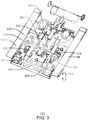
- Fig. 3 is an illustration of a perspective view of a self-locking hinge of the computing device. As illustrated in Fig. 3 , the stand 104 is in a closed position. In embodiments, the closed position is when the stand 104 is substantially parallel to a plane defined by a back plate, generally indicated at 302.
- a self-locking hinge 300 may include a shaft 304. As discussed above, the hinge 300 may be self-locking such that a locking mechanism applies increasing pressure to sliding component 306, 308 based on an increasing force of movement associated with the sliding component 306, 308.
- the hinge 300 includes the backing plate 302, the shaft 300, a shaft 304, and a plurality of sliding components 306, 308.
- the shaft 304 may be coupled to the sliding components 306, 308 as indicated by 307, 309.
- the coupling components at 307, 309 may include ridges that can be engaged by the shaft 304 by ridges on the shaft 304.
- the ridges of the coupling components 307, 309 when in contact with the ridges of the shaft 304 may move the sliding components in opposite directions. Rotational movement, as indicated at 310, results in translational movement of the sliding components 306, 308, as indicated at 312 and 314.
- the self-locking hinge 300 may include a locking mechanism having locking components indicated at 316 and 318. As illustrated in Fig. 3 , the locking components 316, 318 may define an opening through which the sliding components 306 and 308 may respectively move. As discussed in more detail below, the locking components 316 and 318 may inhibit movement of the sliding components 306 and 308. As illustrated in Fig. 3 , levers 320 and 322 may be used to reduce the amount of force that is required to release the locking components 316 and 318.
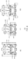
- Fig. 4 is an illustration of a self-locking hinge wherein rotational movement of the shaft results in translational movement of sliding components.
- the locking components 316, 318 are not perpendicular to the sliding components 306, 308.
- the sliding components 306, 308 are inhibited from movement due to frictional forces occurring between the locking components 316, 318 and the sliding components 306, 308, respectively.
- the locking components 316, 318 are more perpendicular to the sliding components 306, 308 in comparison to the position 402, resulting in relatively less inhibition of movement of the sliding components 306, 308.
- locking components 316, 318 are more perpendicular to the sliding components 306, 308 in comparison to the position 402, and 404, resulting in relatively less inhibition of movement of the sliding components 306, 308.
- the translational movement of the sliding components 306, 308 in Fig. 3 and 4 may be one embodiment of translational movement that results from rotational movement of the shaft 304. Other embodiments are possible wherein rotational movement results in translational movement of sliding components in a self-locking mechanism.
- Fig. 5 is an example illustration of a self-locking hinge wherein cables couple the shaft to the sliding components.
- the self-locking hinge 500 includes a rotational shaft 502, a backing plate 504, sliding components 506 and 508, and locking components 510 and 512.
- the shaft 502 is coupled to the sliding components 506, 508 by cables, indicated at 514.
- Rotational movement in the shaft, as indicated at 516, results in translational movement of the sliding components 506, 508, each in an opposite direction from one another.
- the translational movement of the sliding components 506, 508 is a plane parallel to the backing plate 504. Similar to the self-locking hinge 300 discussed in relation to Fig. 3 , locking components 508, 510 inhibit movement of the sliding components 506, 508 due to a force of friction respectively between the locking components 508, 510, and the sliding components 506, 508.
- the self-locking hinge 500 includes a spring 522.
- the spring 522 is configured to apply pressure to at least one of the locking components, such as locking component 510.
- the spring 522 may apply pressure to create friction between the locking component 510 and the sliding component 506.
- the self-locking hinge 500 may include multiple springs, such as a spring to apply pressure against the locking component 512.
- the force of friction may be configured to be less than a force exerted by a user when rotating the shaft 502 by movement of a stand (not shown) configured to be coupled to the shaft 502 as the fastening holes 518, 520 defined by the shaft 502.
- the force of friction may be overcome mechanically, such as when a user adjusts an angle of a computing device by manual force, or electromechanically, wherein a user may initiate an electronic motor to adjust an angle of the computing device.
- the self-locking hinge 500 includes a tensioner 524.
- the tensioner 524 is a tensioning mechanism configured to reduce flexes in the self-locking hinge between the cables 514, the sliders 506, 508, and the shaft 518.
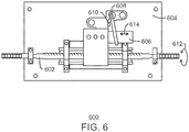
- Fig. 6 is an example illustration of a self-locking hinge wherein rotational movement of the shaft results in translational movement of the sliding component parallel to the shaft.
- the self-locking hinge 600 includes a shaft, 602, a backing plate 604, a sliding component 606, a locking component 608, and a spring 610. Rotation in the shaft 602, indicated by the arrow 612, may result in translational movement of the sliding component 606 as indicated by the arrow 614. Similar to the embodiments discussed above, the locking component 608 may inhibit movement of the sliding component 606 when the sliding component 606 is disposed at a non-perpendicular angle with respect to the sliding component 608.
- the spring 610 may apply pressure to the locking component 608 such that a non-perpendicular angle of the locking component 608 may be achieved. As discussed above, rotational movement of the shaft 602 results in translational movement of the sliding component 606 in the plane of the backing plate 604.
- Fig. 7 is a block diagram illustrating a method for forming a hinge of a computing device.
- the method 700 may include forming, at block 702, a shaft to move rotationally.
- the rotational movement of the shaft may enable a stand to swivel about an axis defined by the shaft, and about the back side of a computing device, such as an All-In-One (AIO) computing device.
- AIO All-In-One
- a sliding component is formed.
- the sliding component is to move translationally as a result of rotational movement of the shaft.
- the method 700 may also include forming, at block 706, a locking mechanism.
- the locking mechanism may include a locking component defining an opening, wherein the sliding component is to move translationally through the opening.
- the locking mechanism may include a spring to apply pressure to the locking component; wherein movement of the sliding component is inhibited by the pressure applied to the locking component.
- the techniques described herein include a method of forming a hinge for a computing device.
- the method includes forming a shaft to move rotationally and a sliding means, such as a sliding component, to move translationally as a result of the movement of the shaft.
- the method may also include forming a locking means.
- the locking means may be a locking mechanism used to inhibit translational movement of the sliding means.
- the hinge may be formed of a material of relative high hardness. In some scenarios, the hinge is formed through a mechanical, chemical, or metallurgical means to increase a hardness of the hinge.
- the locking means includes a locking component.
- the locking component may have an opening wherein the sliding means can translationally move through the opening.
- the locking means includes a spring to apply pressure to the locking component. In some scenarios, the movement of the sliding means is inhibited by the pressure applied to the locking component.
- the embodiments described herein include a hinge for a computing device.
- the hinge includes a shaft to move rotationally and a sliding means, such as a sliding component, to move translationally as a result of the movement of the shaft.
- the hinge may also include a locking means.
- the locking means may be a locking mechanism used to inhibit translational movement of the sliding means.
- the locking means includes a locking component.
- the locking component may have an opening wherein the sliding means can translationally move through the opening.
- the locking means includes a spring to apply pressure to the locking component. In some scenarios, the movement of the sliding means is inhibited by the pressure applied to the locking component. In one scenario, the movement of the sliding means is relatively uninhibited by the locking means when the locking component is perpendicular to the sliding means in comparison to when the locking component is not perpendicular to the sliding means.
- the hinge may also include a backplate to couple the shaft to a backside of the computing device.
- the translational movement of the sliding means is in the plane of the backplate.
- the embodiments described herein include a hinge system for a computing device.
- the hinge system includes a backplate coupled to a backside of a display of the computing device.
- the hinge system also includes a shaft to move rotationally and a sliding component move translationally as a result of the movement of the shaft.
- the sliding component is to move translationally in a plane defined by the backplate.
- the hinge system may also include a locking mechanism.
- the locking means may be a locking mechanism used to inhibit translational movement of the sliding component.
- the locking mechanism includes a locking component.
- the locking component may have an opening wherein the sliding component can translationally move through the opening.
- the locking mechanism includes a spring to apply pressure to the locking component.
- the movement of the sliding component is inhibited by the pressure applied to the locking component.
- the movement of the sliding component is relatively uninhibited by the locking mechanism when the locking component is perpendicular to the sliding component in comparison to when the locking component is not perpendicular to the sliding component.
- An embodiment is an implementation or example.
- Reference in the specification to "an embodiment,” “one embodiment,” “some embodiments,” “various embodiments,” or “other embodiments” means that a particular feature, structure, or characteristic described in connection with the embodiments is included in at least some embodiments, but not necessarily all embodiments, of the present techniques.
- the various appearances of "an embodiment,” “one embodiment,” or “some embodiments” are not necessarily all referring to the same embodiments.
- the elements in some cases may each have a same reference number or a different reference number to suggest that the elements represented could be different and/or similar.
- an element may be flexible enough to have different implementations and work with some or all of the systems shown or described herein.
- the various elements shown in the figures may be the same or different. Which one is referred to as a first element and which is called a second element is arbitrary.
Landscapes
- Engineering & Computer Science (AREA)
- Computer Hardware Design (AREA)
- Theoretical Computer Science (AREA)
- Human Computer Interaction (AREA)
- Physics & Mathematics (AREA)
- General Engineering & Computer Science (AREA)
- General Physics & Mathematics (AREA)
- Mechanical Engineering (AREA)
- Pivots And Pivotal Connections (AREA)
- Telephone Set Structure (AREA)
- Casings For Electric Apparatus (AREA)
Description
- This disclosure relates generally to techniques for hinge systems of a computing device. Specifically, this disclosure relates to a hinge having a rotational shaft that results in translational movement of a sliding component.
- Computing devices may include certain hinges to enable a user to adjust an angle of a component based on a given situation. With the fast growth of computing devices, lighter, thinner computing devices are increasingly preferred by users. In some scenarios, a computing device may include a portable All-in-One (AIO) wherein the display and the processing components are located within the same housing. A hinge may enable a user to adjust the angle of the display to achieve a desired viewing angle.
-
US 2010/171671 A1 describes a stand device comprising a hinge pertaining to the features of the preamble of the independent claims. -
-
Fig. 1A is an illustration of a front view of a computing device including a self-locking hinge; -
Fig. 1B is an illustration of a side view of a computing device having legs coupled to a self-locking hinge; -
Fig. 2 is an illustration of rotational movement of legs of the computing device; -
Fig. 3 is an illustration of a perspective view of a self-locking hinge of the computing device; -
Fig. 4 is an illustration of a self-locking hinge wherein rotational movement of the shaft results in translational movement of sliding components; -
Fig. 5 is an example illustration of a self-locking hinge wherein cables couple the shaft to the sliding components; -
Fig. 6 is an example illustration of a self-locking hinge wherein rotational movement of the shaft results in translational movement of the sliding component parallel to the shaft; and -
Fig. 7 is a block diagram illustrating a method for forming a hinge of a computing device. - The same numbers are used throughout the disclosure and the figures to reference like components and features. Numbers in the 100 series refer to features originally found in
Fig. 1 ; numbers in the 200 series refer to features originally found inFig. 2 ; and so on. - The invention is defined by the independent claims. Further aspects of the invention are outlined in the dependent claims. In the following, if the term "embodiment" relates to unclaimed combinations of features, said term has to be understood as referring to non-claimed matter considered to be useful for highlighting specific aspects of the claimed subject-matter.
- The present disclosure relates generally to techniques for implementing a hinge of a computing device wherein rotational movement is converted to translational movement of components that may be held in place and released from a held position using a locking mechanism. As discussed above, a hinge may enable a user to adjust the angle of the display to achieve a desired viewing angle. In this scenario, once a desired angle is achieved at a given angle, the embodiments described herein include a locking mechanism to inhibit movement of the hinge. The locking mechanism is self-locking wherein the locking mechanism inhibits translational movement of the sliding component such that the locking mechanism applies increasing pressure to the sliding component based on an increasing force of movement associated with the sliding component.
-
Fig. 1A is an illustration of a front view of a computing device including a self-locking hinge. Thecomputing device 100 may be any type of computing device comprising a desktop computer, a All-In-One (AIO) computer, a laptop computer, a tablet computer, a mobile phone, and the like. The computing device includes a self-locking hinge 102. As discussed in more detail below, the self-locking hinge converts rotational movement into translational movement as well as providing a self-locking feature. -
Fig. 1B is an illustration of a side view of a computing device having legs coupled to a self-locking hinge. Thecomputing device 100 may include astand 104. The stand may also be designed to additionally act as a handle. Thestand 104 may be rotational as indicated by thearrow 106. In embodiments, thestand 104 may be legs configured to rotate about an axis defined by a rotational shaft of the self-locking hinge. As discussed in more detail below, rotation of thestand 104 may result in rotation of a shaft of the self-locking hinge 102, as well as translational movement of sliding components of the self-locking hinge 102. -
Fig. 2 is an illustration of rotational movement of legs of the computing device. At 202, thestand 104 is in an extended position enabling thecomputing device 100 to be in an upright position. At 204, thestand 104 is rotated, as indicated by thearrow 206, to be substantially perpendicular to a back side of thecomputing device 100. Atblock 206, thestand 104 is rotated to a closed position in which thestand 104 is substantially parallel to the back side of the computing device. -
Fig. 3 is an illustration of a perspective view of a self-locking hinge of the computing device. As illustrated inFig. 3 , thestand 104 is in a closed position. In embodiments, the closed position is when thestand 104 is substantially parallel to a plane defined by a back plate, generally indicated at 302. - A self-
locking hinge 300 may include ashaft 304. As discussed above, thehinge 300 may be self-locking such that a locking mechanism applies increasing pressure to slidingcomponent sliding component - In the example embodiment illustrated in
Fig. 3 , thehinge 300 includes thebacking plate 302, theshaft 300, ashaft 304, and a plurality ofsliding components shaft 304 may be coupled to thesliding components shaft 304 by ridges on theshaft 304. In this scenario, the ridges of thecoupling components shaft 304 may move the sliding components in opposite directions. Rotational movement, as indicated at 310, results in translational movement of thesliding components locking hinge 300 may include a locking mechanism having locking components indicated at 316 and 318. As illustrated inFig. 3 , thelocking components sliding components locking components sliding components Fig. 3 ,levers locking components -
Fig. 4 is an illustration of a self-locking hinge wherein rotational movement of the shaft results in translational movement of sliding components. As illustrated at theposition 402, thelocking components sliding components position 402, thesliding components locking components sliding components locking components sliding components position 402, resulting in relatively less inhibition of movement of thesliding components components components position components - The translational movement of the sliding
components Fig. 3 and4 may be one embodiment of translational movement that results from rotational movement of theshaft 304. Other embodiments are possible wherein rotational movement results in translational movement of sliding components in a self-locking mechanism. -
Fig. 5 is an example illustration of a self-locking hinge wherein cables couple the shaft to the sliding components. The self-lockinghinge 500 includes arotational shaft 502, abacking plate 504, slidingcomponents components shaft 502 is coupled to the slidingcomponents components components backing plate 504. Similar to the self-lockinghinge 300 discussed in relation toFig. 3 , lockingcomponents components components components - In embodiments, the self-locking
hinge 500 includes aspring 522. Thespring 522 is configured to apply pressure to at least one of the locking components, such aslocking component 510. Thespring 522 may apply pressure to create friction between the lockingcomponent 510 and the slidingcomponent 506. Although not illustrated inFig. 5 , the self-lockinghinge 500 may include multiple springs, such as a spring to apply pressure against thelocking component 512. In embodiments, the force of friction may be configured to be less than a force exerted by a user when rotating theshaft 502 by movement of a stand (not shown) configured to be coupled to theshaft 502 as the fastening holes 518, 520 defined by theshaft 502. In some embodiments, the force of friction may be overcome mechanically, such as when a user adjusts an angle of a computing device by manual force, or electromechanically, wherein a user may initiate an electronic motor to adjust an angle of the computing device. - In embodiments, the self-locking
hinge 500 includes atensioner 524. Thetensioner 524 is a tensioning mechanism configured to reduce flexes in the self-locking hinge between thecables 514, thesliders shaft 518. -
Fig. 6 is an example illustration of a self-locking hinge wherein rotational movement of the shaft results in translational movement of the sliding component parallel to the shaft. The self-lockinghinge 600 includes a shaft, 602, abacking plate 604, a slidingcomponent 606, alocking component 608, and aspring 610. Rotation in theshaft 602, indicated by thearrow 612, may result in translational movement of the slidingcomponent 606 as indicated by thearrow 614. Similar to the embodiments discussed above, thelocking component 608 may inhibit movement of the slidingcomponent 606 when the slidingcomponent 606 is disposed at a non-perpendicular angle with respect to the slidingcomponent 608. In embodiments, thespring 610 may apply pressure to thelocking component 608 such that a non-perpendicular angle of thelocking component 608 may be achieved. As discussed above, rotational movement of theshaft 602 results in translational movement of the slidingcomponent 606 in the plane of thebacking plate 604. - Various self-locking hinge embodiments are discussed above. Other embodiments, such as a rack and pinion arrangement including one or more locking components are also contemplated.
-
Fig. 7 is a block diagram illustrating a method for forming a hinge of a computing device. Themethod 700 may include forming, atblock 702, a shaft to move rotationally. The rotational movement of the shaft may enable a stand to swivel about an axis defined by the shaft, and about the back side of a computing device, such as an All-In-One (AIO) computing device. Atblock 704, a sliding component is formed. The sliding component is to move translationally as a result of rotational movement of the shaft. - The
method 700 may also include forming, atblock 706, a locking mechanism. The locking mechanism may include a locking component defining an opening, wherein the sliding component is to move translationally through the opening. The locking mechanism may include a spring to apply pressure to the locking component; wherein movement of the sliding component is inhibited by the pressure applied to the locking component. - The techniques described herein include a method of forming a hinge for a computing device. The method includes forming a shaft to move rotationally and a sliding means, such as a sliding component, to move translationally as a result of the movement of the shaft. The method may also include forming a locking means. The locking means may be a locking mechanism used to inhibit translational movement of the sliding means.
- The hinge may be formed of a material of relative high hardness. In some scenarios, the hinge is formed through a mechanical, chemical, or metallurgical means to increase a hardness of the hinge.
- The locking means includes a locking component. The locking component may have an opening wherein the sliding means can translationally move through the opening. The locking means includes a spring to apply pressure to the locking component. In some scenarios, the movement of the sliding means is inhibited by the pressure applied to the locking component.
- The embodiments described herein include a hinge for a computing device. The hinge includes a shaft to move rotationally and a sliding means, such as a sliding component, to move translationally as a result of the movement of the shaft. The hinge may also include a locking means. The locking means may be a locking mechanism used to inhibit translational movement of the sliding means.
- The locking means includes a locking component. The locking component may have an opening wherein the sliding means can translationally move through the opening. The locking means includes a spring to apply pressure to the locking component. In some scenarios, the movement of the sliding means is inhibited by the pressure applied to the locking component. In one scenario, the movement of the sliding means is relatively uninhibited by the locking means when the locking component is perpendicular to the sliding means in comparison to when the locking component is not perpendicular to the sliding means.
- The hinge may also include a backplate to couple the shaft to a backside of the computing device. The translational movement of the sliding means is in the plane of the backplate.
- The embodiments described herein include a hinge system for a computing device. The hinge system includes a backplate coupled to a backside of a display of the computing device. The hinge system also includes a shaft to move rotationally and a sliding component move translationally as a result of the movement of the shaft. The sliding component is to move translationally in a plane defined by the backplate.
- The hinge system may also include a locking mechanism. The locking means may be a locking mechanism used to inhibit translational movement of the sliding component. The locking mechanism includes a locking component. The locking component may have an opening wherein the sliding component can translationally move through the opening. The locking mechanism includes a spring to apply pressure to the locking component. In some scenarios, the movement of the sliding component is inhibited by the pressure applied to the locking component. In one scenario, the movement of the sliding component is relatively uninhibited by the locking mechanism when the locking component is perpendicular to the sliding component in comparison to when the locking component is not perpendicular to the sliding component.
- An embodiment is an implementation or example. Reference in the specification to "an embodiment," "one embodiment," "some embodiments," "various embodiments," or "other embodiments" means that a particular feature, structure, or characteristic described in connection with the embodiments is included in at least some embodiments, but not necessarily all embodiments, of the present techniques. The various appearances of "an embodiment," "one embodiment," or "some embodiments" are not necessarily all referring to the same embodiments.
- Not all components, features, structures, characteristics, etc. described and illustrated herein need be included in a particular embodiment or embodiments. If the specification states a component, feature, structure, or characteristic "may", "might", "can" or "could" be included, for example, that particular component, feature, structure, or characteristic is not required to be included. If the specification or claim refers to "a" or "an" element, that does not mean there is only one of the element. If the specification or claims refer to "an additional" element, that does not preclude there being more than one of the additional element.
- It is to be noted that, although some embodiments have been described in reference to particular implementations, other implementations are possible according to some embodiments. Additionally, the arrangement and/or order of circuit elements or other features illustrated in the drawings and/or described herein need not be arranged in the particular way illustrated and described. Many other arrangements are possible according to some embodiments.
- In each system shown in a figure, the elements in some cases may each have a same reference number or a different reference number to suggest that the elements represented could be different and/or similar. However, an element may be flexible enough to have different implementations and work with some or all of the systems shown or described herein. The various elements shown in the figures may be the same or different. Which one is referred to as a first element and which is called a second element is arbitrary.
- It is to be understood that specifics in the aforementioned examples may be used anywhere in one or more embodiments. For instance, all optional features of the computing device described above may also be implemented with respect to either of the methods or the computer-readable medium described herein. Furthermore, although flow diagrams and/or state diagrams may have been used herein to describe embodiments, the techniques are not limited to those diagrams or to corresponding descriptions herein. For example, flow need not move through each illustrated box or state or in exactly the same order as illustrated and described herein.
- The present invention is not restricted to the particular details listed herein. Indeed, those skilled in the art having the benefit of this disclosure will appreciate that many other variations from the foregoing description and drawings may be made within the scope of the present invention, which is defined in the appended claims.
Claims (12)
- A method (700) of forming a hinge for a computing device, comprising:forming (702) a shaft to move rotationally;forming (704) a sliding component to move translationally as a result of rotational movement of the shaft; andforming (706) a locking mechanism, wherein the locking mechanism is adapted to inhibit translational movement of the sliding component via locking components that are configured to apply a force to the sliding component,characterized in that the locking mechanism is self-locking such that the locking mechanism applies increasing pressure to the sliding component based on an increasing frictional force between the sliding component and the locking mechanism, the locking component (316, 318) defining an opening, wherein the sliding component (306, 308) is to move translationally through the opening; andthe locking mechanism further comprises a spring (522) to apply pressure to the locking component, wherein movement of the sliding component is inhibited by the pressure applied to the locking component resulting in an increased pressure on the sliding component.
- The method (700) of claim 1, wherein the hinge is formed of a material of high hardness, or is formed through mechanical, chemical, or metallurgical means to increase a hardness of the hinge.
- The method (700) of claim 1 or 2, wherein movement of the sliding component is relatively uninhibited by the locking mechanism when the locking component is perpendicular to the sliding component in comparison to when the locking component is not perpendicular to the sliding component.
- The method (700) of any combination of claims 1-3, comprising forming a back plate to be couple the shaft to a back side computing device, wherein the translational movement of the sliding component is in plane of the back plate.
- The method (700) of any combination of claims 1-4, wherein the shaft is to be coupled to legs of the computing device, such that rotation of the legs results in rotational movement in the shaft, translational movement of the sliding component, and rotational movement in the backplate.
- The method (700) of any combination of claims 1-5, wherein the computing device is an all-in-one (AIO) computing device.
- The method (700) of any combination of claims 1-6, wherein the sliding component is coupled to the shaft such that rotational movement of the shaft results in translational movement of the sliding component.
- A hinge (300) for a computing device, comprising:a shaft (304) configured to move rotationally;a sliding component (306, 308) configured to move translationally as a result of rotational movement of the shaft; anda locking mechanism, wherein the locking mechanism is adapted to inhibit translational movement of the sliding component via a locking component (316, 318) configured to apply a force to the sliding component,characterized in that the locking mechanism is self-locking such that the locking mechanism is configured to apply increasing pressure to the sliding component based on an increasing frictional force between the sliding component and the locking mechanism, the locking component (316, 318) defining an opening, wherein the sliding component (306, 308) is configured to move translationally through the opening; andthe hinge further comprises a spring (522) configured to apply pressure to the locking component, wherein movement of the sliding component is inhibited by the pressure applied to the locking component resulting in an increased pressure on the sliding component.
- The hinge (300) of claim 8, wherein movement of the sliding component (306, 308) is relatively uninhibited by the locking mechanism when the locking component (316, 318) is perpendicular to the sliding component in comparison to when the locking component is not perpendicular to the sliding component.
- The hinge (300) of claim 8 or 9, comprising a back plate (302) configured to couple the shaft (304) to a back side of the computing device, wherein the translational movement of the sliding component (306, 308) is in plane of the back plate.
- The hinge (300) of any combination of claims 8-10, comprising legs of the computing device, wherein the shaft (304) is configured to be coupled to the legs such that rotation of the legs results in rotational movement in the shaft, translational movement of the sliding component (306, 308), and rotational movement in the backplate.
- The hinge (300) of any combination of claims 8-11, wherein the computing device is an all-in-one (AIO) computing device.
Applications Claiming Priority (2)
| Application Number | Priority Date | Filing Date | Title |
|---|---|---|---|
| US14/141,196 US9551177B2 (en) | 2013-12-26 | 2013-12-26 | Rotational to translational locking hinge |
| PCT/US2014/067076 WO2015099928A1 (en) | 2013-12-26 | 2014-11-24 | Rotational to translational locking hinge |
Publications (3)
| Publication Number | Publication Date |
|---|---|
| EP3087449A1 EP3087449A1 (en) | 2016-11-02 |
| EP3087449A4 EP3087449A4 (en) | 2017-09-13 |
| EP3087449B1 true EP3087449B1 (en) | 2020-12-30 |
Family
ID=53479501
Family Applications (1)
| Application Number | Title | Priority Date | Filing Date |
|---|---|---|---|
| EP14874271.1A Active EP3087449B1 (en) | 2013-12-26 | 2014-11-24 | Rotational to translational locking hinge |
Country Status (5)
| Country | Link |
|---|---|
| US (1) | US9551177B2 (en) |
| EP (1) | EP3087449B1 (en) |
| KR (1) | KR101812617B1 (en) |
| CN (1) | CN105765480B (en) |
| WO (1) | WO2015099928A1 (en) |
Families Citing this family (9)
| Publication number | Priority date | Publication date | Assignee | Title |
|---|---|---|---|---|
| US20150277506A1 (en) | 2014-03-29 | 2015-10-01 | Bok Eng Cheah | Micro-hinge for an electronic device |
| US10301858B2 (en) * | 2016-06-14 | 2019-05-28 | Microsoft Technology Licensing, Llc | Hinge mechanism |
| US9840861B1 (en) * | 2016-06-14 | 2017-12-12 | Microsoft Technology Licensing, Llc | Hinged device with snap open lock |
| US10501973B2 (en) | 2016-06-14 | 2019-12-10 | Microsoft Technology Licensing, Llc | Hinge with free-stop function |
| US10061359B2 (en) | 2016-07-28 | 2018-08-28 | Microsoft Technology Licensing, Llc | Hinged device with living hinge |
| US10228732B2 (en) | 2017-05-19 | 2019-03-12 | Microsoft Technology Licensing, Llc | Hinge with variable sliding friction |
| US10545540B2 (en) | 2017-07-06 | 2020-01-28 | Microsoft Technology Licensing, Llc | Systems and methods of longitudinal torsional resistance in a hinge |
| CN111609029B (en) * | 2020-05-22 | 2021-05-04 | 深圳市柔宇科技有限公司 | Folding device and flexible electronic equipment |
| CN113466071B (en) * | 2021-05-28 | 2023-01-24 | 昆明华城兴建材有限公司 | Hardness detection device of cement board |
Family Cites Families (30)
| Publication number | Priority date | Publication date | Assignee | Title |
|---|---|---|---|---|
| US1357740A (en) * | 1917-12-14 | 1920-11-02 | Stephan Jacob | Furniture |
| JP2937687B2 (en) * | 1993-04-26 | 1999-08-23 | 米沢日本電気株式会社 | Movable stand device |
| US6053589A (en) * | 1998-09-10 | 2000-04-25 | Inventec Corp. | Automatic inclination device for a portable computer |
| TWI241141B (en) * | 2003-11-03 | 2005-10-01 | Coretronic Corp | Display stand |
| JP4402448B2 (en) * | 2003-12-24 | 2010-01-20 | 株式会社新鋭産業 | Display monitor stand |
| CN100544563C (en) | 2004-12-30 | 2009-09-23 | 深圳富泰宏精密工业有限公司 | hinge structure |
| JP3112838U (en) * | 2005-05-26 | 2005-08-25 | 船井電機株式会社 | Display device |
| KR100662454B1 (en) * | 2005-07-29 | 2007-01-02 | 엘지전자 주식회사 | Stand structure for flat panel display |
| KR20070084650A (en) * | 2006-02-21 | 2007-08-27 | 삼성전자주식회사 | Stand for display device and display device having same |
| KR101253569B1 (en) * | 2006-05-09 | 2013-04-11 | 삼성전자주식회사 | Supporting device for display device |
| KR100710313B1 (en) * | 2006-05-26 | 2007-04-23 | 엘지전자 주식회사 | Video display device |
| KR100710314B1 (en) * | 2006-06-01 | 2007-04-23 | 엘지전자 주식회사 | Monitor stand |
| CN101101019B (en) | 2006-07-07 | 2010-12-29 | 深圳富泰宏精密工业有限公司 | Hinge device and portable electronic device using same |
| KR100793754B1 (en) * | 2006-07-07 | 2008-01-10 | 엘지전자 주식회사 | Video display device |
| CN101338781B (en) | 2007-07-06 | 2011-03-30 | 深圳富泰宏精密工业有限公司 | Hinge mechanism and portable electronic device applying same |
| CN101487558B (en) * | 2008-01-16 | 2012-01-25 | 鸿富锦精密工业(深圳)有限公司 | Lifting mechanism |
| CN101498396B (en) * | 2008-01-30 | 2011-07-27 | 鸿富锦精密工业(深圳)有限公司 | Lifting mechanism |
| US8413382B2 (en) * | 2008-09-02 | 2013-04-09 | Caterpillar Sarl | Hinge and door unit |
| US7922133B2 (en) * | 2008-09-12 | 2011-04-12 | Shin Zu Shing Co., Ltd. | Flat panel display support |
| KR101408951B1 (en) * | 2009-01-07 | 2014-06-17 | 삼성전자주식회사 | Stand device |
| WO2010094083A1 (en) * | 2009-02-20 | 2010-08-26 | Gryffin Epss Pty Ltd | An adjustable hinge |
| US8402609B2 (en) | 2009-12-31 | 2013-03-26 | Shin Zu Shing Co., Ltd. | Self-lock hinge |
| US8226054B2 (en) * | 2010-10-18 | 2012-07-24 | Syncmold Enterprise Corp. | Display frame and support unit thereof |
| CN102954100A (en) * | 2011-08-18 | 2013-03-06 | 深圳富泰宏精密工业有限公司 | Portable electronic device and rotation assembly thereof |
| TWI485345B (en) * | 2011-09-20 | 2015-05-21 | Compal Electronics Inc | Stand of display device |
| US8891232B2 (en) * | 2011-09-23 | 2014-11-18 | Htc Corporation | Support stand and standable hand-held device |
| US8897033B2 (en) * | 2012-04-25 | 2014-11-25 | Motorola Mobility Llc | Modular kickstand mechanism |
| TWI502142B (en) * | 2012-05-17 | 2015-10-01 | Wistron Corp | Hinge mechanism with easy assembly and electronic device therewith |
| CN104541224B (en) * | 2012-10-31 | 2019-09-06 | 惠普发展公司,有限责任合伙企业 | Flexible Member Panel Brackets |
| US9856079B2 (en) * | 2013-04-09 | 2018-01-02 | Grigooris MANSSOURIAN | Retainer mechanism |
-
2013
- 2013-12-26 US US14/141,196 patent/US9551177B2/en not_active Expired - Fee Related
-
2014
- 2014-11-24 EP EP14874271.1A patent/EP3087449B1/en active Active
- 2014-11-24 CN CN201480064655.3A patent/CN105765480B/en active Active
- 2014-11-24 WO PCT/US2014/067076 patent/WO2015099928A1/en not_active Ceased
- 2014-11-24 KR KR1020167013918A patent/KR101812617B1/en active Active
Non-Patent Citations (1)
| Title |
|---|
| None * |
Also Published As
| Publication number | Publication date |
|---|---|
| KR101812617B1 (en) | 2017-12-27 |
| WO2015099928A1 (en) | 2015-07-02 |
| CN105765480B (en) | 2019-07-02 |
| EP3087449A1 (en) | 2016-11-02 |
| KR20160075733A (en) | 2016-06-29 |
| CN105765480A (en) | 2016-07-13 |
| EP3087449A4 (en) | 2017-09-13 |
| US20150184438A1 (en) | 2015-07-02 |
| US9551177B2 (en) | 2017-01-24 |
Similar Documents
| Publication | Publication Date | Title |
|---|---|---|
| US9551177B2 (en) | Rotational to translational locking hinge | |
| US9696754B2 (en) | Hinge having multiple degrees of freedom | |
| US9939851B2 (en) | Electronic device and hinge thereof | |
| US10000955B2 (en) | Biaxial hinge and terminal device using the same | |
| CN101725624B (en) | Hinge structure | |
| US9857831B2 (en) | Flexible hinges for computing devices | |
| US8947871B2 (en) | Portable electronic device and slide rail device | |
| CN107735743B (en) | Multi-stage friction hinge | |
| EP3516477B1 (en) | Multi-axis hinge | |
| EP2490094B1 (en) | Hinge capable of absorbing stress | |
| TWI520671B (en) | Portable electronic device | |
| US9230606B2 (en) | Mounting apparatus assembly | |
| US20150327383A1 (en) | Torque balancing device applied to synchronous dual-shaft system | |
| EP2940366B1 (en) | Display device holder | |
| US20160259381A1 (en) | Computer housing | |
| US9170613B2 (en) | Connecting assembly and electronic device having the same | |
| CN101660566B (en) | Hinge structure | |
| BR112016026241B1 (en) | FRICTION JOINT AND ROTATING SUPPORT STRUCTURE FOR TABLET COMPUTERS | |
| US8964381B2 (en) | Electronic device locking/unlocking mechanism | |
| CN102118937A (en) | Portable electronic apparatus | |
| US9395755B2 (en) | Dock for controlling and adjusting viewing angle of electronic devices | |
| US20200194987A1 (en) | Non-adhesive cable clip and electronic device using same | |
| US8891248B2 (en) | Angle-adjustable support with pivot mechanism | |
| US20170343152A1 (en) | Supporting structure and display device using the same | |
| US20190108860A1 (en) | Tool-less mounting apparatus for hard disk drive and storage device using the same |
Legal Events
| Date | Code | Title | Description |
|---|---|---|---|
| PUAI | Public reference made under article 153(3) epc to a published international application that has entered the european phase |
Free format text: ORIGINAL CODE: 0009012 |
|
| 17P | Request for examination filed |
Effective date: 20160520 |
|
| AK | Designated contracting states |
Kind code of ref document: A1 Designated state(s): AL AT BE BG CH CY CZ DE DK EE ES FI FR GB GR HR HU IE IS IT LI LT LU LV MC MK MT NL NO PL PT RO RS SE SI SK SM TR |
|
| AX | Request for extension of the european patent |
Extension state: BA ME |
|
| DAX | Request for extension of the european patent (deleted) | ||
| A4 | Supplementary search report drawn up and despatched |
Effective date: 20170811 |
|
| RIC1 | Information provided on ipc code assigned before grant |
Ipc: G06F 1/16 20060101AFI20170807BHEP |
|
| STAA | Information on the status of an ep patent application or granted ep patent |
Free format text: STATUS: EXAMINATION IS IN PROGRESS |
|
| 17Q | First examination report despatched |
Effective date: 20200117 |
|
| GRAP | Despatch of communication of intention to grant a patent |
Free format text: ORIGINAL CODE: EPIDOSNIGR1 |
|
| STAA | Information on the status of an ep patent application or granted ep patent |
Free format text: STATUS: GRANT OF PATENT IS INTENDED |
|
| INTG | Intention to grant announced |
Effective date: 20200720 |
|
| GRAS | Grant fee paid |
Free format text: ORIGINAL CODE: EPIDOSNIGR3 |
|
| GRAA | (expected) grant |
Free format text: ORIGINAL CODE: 0009210 |
|
| STAA | Information on the status of an ep patent application or granted ep patent |
Free format text: STATUS: THE PATENT HAS BEEN GRANTED |
|
| AK | Designated contracting states |
Kind code of ref document: B1 Designated state(s): AL AT BE BG CH CY CZ DE DK EE ES FI FR GB GR HR HU IE IS IT LI LT LU LV MC MK MT NL NO PL PT RO RS SE SI SK SM TR |
|
| REG | Reference to a national code |
Ref country code: GB Ref legal event code: FG4D |
|
| REG | Reference to a national code |
Ref country code: DE Ref legal event code: R096 Ref document number: 602014073887 Country of ref document: DE |
|
| REG | Reference to a national code |
Ref country code: AT Ref legal event code: REF Ref document number: 1350571 Country of ref document: AT Kind code of ref document: T Effective date: 20210115 |
|
| REG | Reference to a national code |
Ref country code: IE Ref legal event code: FG4D |
|
| REG | Reference to a national code |
Ref country code: NL Ref legal event code: FP |
|
| PG25 | Lapsed in a contracting state [announced via postgrant information from national office to epo] |
Ref country code: NO Free format text: LAPSE BECAUSE OF FAILURE TO SUBMIT A TRANSLATION OF THE DESCRIPTION OR TO PAY THE FEE WITHIN THE PRESCRIBED TIME-LIMIT Effective date: 20210330 Ref country code: FI Free format text: LAPSE BECAUSE OF FAILURE TO SUBMIT A TRANSLATION OF THE DESCRIPTION OR TO PAY THE FEE WITHIN THE PRESCRIBED TIME-LIMIT Effective date: 20201230 Ref country code: RS Free format text: LAPSE BECAUSE OF FAILURE TO SUBMIT A TRANSLATION OF THE DESCRIPTION OR TO PAY THE FEE WITHIN THE PRESCRIBED TIME-LIMIT Effective date: 20201230 Ref country code: GR Free format text: LAPSE BECAUSE OF FAILURE TO SUBMIT A TRANSLATION OF THE DESCRIPTION OR TO PAY THE FEE WITHIN THE PRESCRIBED TIME-LIMIT Effective date: 20210331 |
|
| REG | Reference to a national code |
Ref country code: AT Ref legal event code: MK05 Ref document number: 1350571 Country of ref document: AT Kind code of ref document: T Effective date: 20201230 |
|
| PG25 | Lapsed in a contracting state [announced via postgrant information from national office to epo] |
Ref country code: BG Free format text: LAPSE BECAUSE OF FAILURE TO SUBMIT A TRANSLATION OF THE DESCRIPTION OR TO PAY THE FEE WITHIN THE PRESCRIBED TIME-LIMIT Effective date: 20210330 Ref country code: LV Free format text: LAPSE BECAUSE OF FAILURE TO SUBMIT A TRANSLATION OF THE DESCRIPTION OR TO PAY THE FEE WITHIN THE PRESCRIBED TIME-LIMIT Effective date: 20201230 Ref country code: SE Free format text: LAPSE BECAUSE OF FAILURE TO SUBMIT A TRANSLATION OF THE DESCRIPTION OR TO PAY THE FEE WITHIN THE PRESCRIBED TIME-LIMIT Effective date: 20201230 |
|
| PG25 | Lapsed in a contracting state [announced via postgrant information from national office to epo] |
Ref country code: HR Free format text: LAPSE BECAUSE OF FAILURE TO SUBMIT A TRANSLATION OF THE DESCRIPTION OR TO PAY THE FEE WITHIN THE PRESCRIBED TIME-LIMIT Effective date: 20201230 |
|
| REG | Reference to a national code |
Ref country code: LT Ref legal event code: MG9D |
|
| PG25 | Lapsed in a contracting state [announced via postgrant information from national office to epo] |
Ref country code: LT Free format text: LAPSE BECAUSE OF FAILURE TO SUBMIT A TRANSLATION OF THE DESCRIPTION OR TO PAY THE FEE WITHIN THE PRESCRIBED TIME-LIMIT Effective date: 20201230 Ref country code: PT Free format text: LAPSE BECAUSE OF FAILURE TO SUBMIT A TRANSLATION OF THE DESCRIPTION OR TO PAY THE FEE WITHIN THE PRESCRIBED TIME-LIMIT Effective date: 20210430 Ref country code: RO Free format text: LAPSE BECAUSE OF FAILURE TO SUBMIT A TRANSLATION OF THE DESCRIPTION OR TO PAY THE FEE WITHIN THE PRESCRIBED TIME-LIMIT Effective date: 20201230 Ref country code: SK Free format text: LAPSE BECAUSE OF FAILURE TO SUBMIT A TRANSLATION OF THE DESCRIPTION OR TO PAY THE FEE WITHIN THE PRESCRIBED TIME-LIMIT Effective date: 20201230 Ref country code: CZ Free format text: LAPSE BECAUSE OF FAILURE TO SUBMIT A TRANSLATION OF THE DESCRIPTION OR TO PAY THE FEE WITHIN THE PRESCRIBED TIME-LIMIT Effective date: 20201230 Ref country code: EE Free format text: LAPSE BECAUSE OF FAILURE TO SUBMIT A TRANSLATION OF THE DESCRIPTION OR TO PAY THE FEE WITHIN THE PRESCRIBED TIME-LIMIT Effective date: 20201230 |
|
| PG25 | Lapsed in a contracting state [announced via postgrant information from national office to epo] |
Ref country code: PL Free format text: LAPSE BECAUSE OF FAILURE TO SUBMIT A TRANSLATION OF THE DESCRIPTION OR TO PAY THE FEE WITHIN THE PRESCRIBED TIME-LIMIT Effective date: 20201230 Ref country code: AT Free format text: LAPSE BECAUSE OF FAILURE TO SUBMIT A TRANSLATION OF THE DESCRIPTION OR TO PAY THE FEE WITHIN THE PRESCRIBED TIME-LIMIT Effective date: 20201230 |
|
| PG25 | Lapsed in a contracting state [announced via postgrant information from national office to epo] |
Ref country code: IS Free format text: LAPSE BECAUSE OF FAILURE TO SUBMIT A TRANSLATION OF THE DESCRIPTION OR TO PAY THE FEE WITHIN THE PRESCRIBED TIME-LIMIT Effective date: 20210430 |
|
| REG | Reference to a national code |
Ref country code: DE Ref legal event code: R097 Ref document number: 602014073887 Country of ref document: DE |
|
| PG25 | Lapsed in a contracting state [announced via postgrant information from national office to epo] |
Ref country code: AL Free format text: LAPSE BECAUSE OF FAILURE TO SUBMIT A TRANSLATION OF THE DESCRIPTION OR TO PAY THE FEE WITHIN THE PRESCRIBED TIME-LIMIT Effective date: 20201230 Ref country code: IT Free format text: LAPSE BECAUSE OF FAILURE TO SUBMIT A TRANSLATION OF THE DESCRIPTION OR TO PAY THE FEE WITHIN THE PRESCRIBED TIME-LIMIT Effective date: 20201230 |
|
| PLBE | No opposition filed within time limit |
Free format text: ORIGINAL CODE: 0009261 |
|
| STAA | Information on the status of an ep patent application or granted ep patent |
Free format text: STATUS: NO OPPOSITION FILED WITHIN TIME LIMIT |
|
| PG25 | Lapsed in a contracting state [announced via postgrant information from national office to epo] |
Ref country code: DK Free format text: LAPSE BECAUSE OF FAILURE TO SUBMIT A TRANSLATION OF THE DESCRIPTION OR TO PAY THE FEE WITHIN THE PRESCRIBED TIME-LIMIT Effective date: 20201230 Ref country code: ES Free format text: LAPSE BECAUSE OF FAILURE TO SUBMIT A TRANSLATION OF THE DESCRIPTION OR TO PAY THE FEE WITHIN THE PRESCRIBED TIME-LIMIT Effective date: 20201230 |
|
| 26N | No opposition filed |
Effective date: 20211001 |
|
| PG25 | Lapsed in a contracting state [announced via postgrant information from national office to epo] |
Ref country code: SI Free format text: LAPSE BECAUSE OF FAILURE TO SUBMIT A TRANSLATION OF THE DESCRIPTION OR TO PAY THE FEE WITHIN THE PRESCRIBED TIME-LIMIT Effective date: 20201230 |
|
| PG25 | Lapsed in a contracting state [announced via postgrant information from national office to epo] |
Ref country code: IS Free format text: LAPSE BECAUSE OF FAILURE TO SUBMIT A TRANSLATION OF THE DESCRIPTION OR TO PAY THE FEE WITHIN THE PRESCRIBED TIME-LIMIT Effective date: 20210430 |
|
| PG25 | Lapsed in a contracting state [announced via postgrant information from national office to epo] |
Ref country code: MC Free format text: LAPSE BECAUSE OF FAILURE TO SUBMIT A TRANSLATION OF THE DESCRIPTION OR TO PAY THE FEE WITHIN THE PRESCRIBED TIME-LIMIT Effective date: 20201230 |
|
| REG | Reference to a national code |
Ref country code: CH Ref legal event code: PL |
|
| PG25 | Lapsed in a contracting state [announced via postgrant information from national office to epo] |
Ref country code: LU Free format text: LAPSE BECAUSE OF NON-PAYMENT OF DUE FEES Effective date: 20211124 Ref country code: BE Free format text: LAPSE BECAUSE OF NON-PAYMENT OF DUE FEES Effective date: 20211130 |
|
| REG | Reference to a national code |
Ref country code: BE Ref legal event code: MM Effective date: 20211130 |
|
| PG25 | Lapsed in a contracting state [announced via postgrant information from national office to epo] |
Ref country code: LI Free format text: LAPSE BECAUSE OF NON-PAYMENT OF DUE FEES Effective date: 20211130 Ref country code: CH Free format text: LAPSE BECAUSE OF NON-PAYMENT OF DUE FEES Effective date: 20211130 |
|
| PG25 | Lapsed in a contracting state [announced via postgrant information from national office to epo] |
Ref country code: IE Free format text: LAPSE BECAUSE OF NON-PAYMENT OF DUE FEES Effective date: 20211124 |
|
| PG25 | Lapsed in a contracting state [announced via postgrant information from national office to epo] |
Ref country code: HU Free format text: LAPSE BECAUSE OF FAILURE TO SUBMIT A TRANSLATION OF THE DESCRIPTION OR TO PAY THE FEE WITHIN THE PRESCRIBED TIME-LIMIT; INVALID AB INITIO Effective date: 20141124 |
|
| P01 | Opt-out of the competence of the unified patent court (upc) registered |
Effective date: 20230518 |
|
| PG25 | Lapsed in a contracting state [announced via postgrant information from national office to epo] |
Ref country code: CY Free format text: LAPSE BECAUSE OF FAILURE TO SUBMIT A TRANSLATION OF THE DESCRIPTION OR TO PAY THE FEE WITHIN THE PRESCRIBED TIME-LIMIT Effective date: 20201230 |
|
| PG25 | Lapsed in a contracting state [announced via postgrant information from national office to epo] |
Ref country code: SM Free format text: LAPSE BECAUSE OF FAILURE TO SUBMIT A TRANSLATION OF THE DESCRIPTION OR TO PAY THE FEE WITHIN THE PRESCRIBED TIME-LIMIT Effective date: 20201230 |
|
| PG25 | Lapsed in a contracting state [announced via postgrant information from national office to epo] |
Ref country code: MK Free format text: LAPSE BECAUSE OF FAILURE TO SUBMIT A TRANSLATION OF THE DESCRIPTION OR TO PAY THE FEE WITHIN THE PRESCRIBED TIME-LIMIT Effective date: 20201230 |
|
| PG25 | Lapsed in a contracting state [announced via postgrant information from national office to epo] |
Ref country code: TR Free format text: LAPSE BECAUSE OF FAILURE TO SUBMIT A TRANSLATION OF THE DESCRIPTION OR TO PAY THE FEE WITHIN THE PRESCRIBED TIME-LIMIT Effective date: 20201230 |
|
| PG25 | Lapsed in a contracting state [announced via postgrant information from national office to epo] |
Ref country code: MT Free format text: LAPSE BECAUSE OF FAILURE TO SUBMIT A TRANSLATION OF THE DESCRIPTION OR TO PAY THE FEE WITHIN THE PRESCRIBED TIME-LIMIT Effective date: 20201230 |
|
| PGFP | Annual fee paid to national office [announced via postgrant information from national office to epo] |
Ref country code: NL Payment date: 20241024 Year of fee payment: 11 |
|
| PGFP | Annual fee paid to national office [announced via postgrant information from national office to epo] |
Ref country code: GB Payment date: 20241017 Year of fee payment: 11 |
|
| PGFP | Annual fee paid to national office [announced via postgrant information from national office to epo] |
Ref country code: FR Payment date: 20241021 Year of fee payment: 11 |
|
| PGFP | Annual fee paid to national office [announced via postgrant information from national office to epo] |
Ref country code: DE Payment date: 20250930 Year of fee payment: 12 |