BR112016026241B1 - FRICTION JOINT AND ROTATING SUPPORT STRUCTURE FOR TABLET COMPUTERS - Google Patents
FRICTION JOINT AND ROTATING SUPPORT STRUCTURE FOR TABLET COMPUTERS Download PDFInfo
- Publication number
- BR112016026241B1 BR112016026241B1 BR112016026241-7A BR112016026241A BR112016026241B1 BR 112016026241 B1 BR112016026241 B1 BR 112016026241B1 BR 112016026241 A BR112016026241 A BR 112016026241A BR 112016026241 B1 BR112016026241 B1 BR 112016026241B1
- Authority
- BR
- Brazil
- Prior art keywords
- friction
- torque
- band
- support
- shaft
- Prior art date
Links
Images


Classifications
-
- G—PHYSICS
- G06—COMPUTING; CALCULATING OR COUNTING
- G06F—ELECTRIC DIGITAL DATA PROCESSING
- G06F1/00—Details not covered by groups G06F3/00 - G06F13/00 and G06F21/00
- G06F1/16—Constructional details or arrangements
-
- H—ELECTRICITY
- H05—ELECTRIC TECHNIQUES NOT OTHERWISE PROVIDED FOR
- H05K—PRINTED CIRCUITS; CASINGS OR CONSTRUCTIONAL DETAILS OF ELECTRIC APPARATUS; MANUFACTURE OF ASSEMBLAGES OF ELECTRICAL COMPONENTS
- H05K5/00—Casings, cabinets or drawers for electric apparatus
- H05K5/02—Details
- H05K5/0217—Mechanical details of casings
- H05K5/0226—Hinges
-
- G—PHYSICS
- G06—COMPUTING; CALCULATING OR COUNTING
- G06F—ELECTRIC DIGITAL DATA PROCESSING
- G06F1/00—Details not covered by groups G06F3/00 - G06F13/00 and G06F21/00
- G06F1/16—Constructional details or arrangements
- G06F1/1613—Constructional details or arrangements for portable computers
- G06F1/1633—Constructional details or arrangements of portable computers not specific to the type of enclosures covered by groups G06F1/1615 - G06F1/1626
- G06F1/1675—Miscellaneous details related to the relative movement between the different enclosures or enclosure parts
- G06F1/1681—Details related solely to hinges
-
- H—ELECTRICITY
- H05—ELECTRIC TECHNIQUES NOT OTHERWISE PROVIDED FOR
- H05K—PRINTED CIRCUITS; CASINGS OR CONSTRUCTIONAL DETAILS OF ELECTRIC APPARATUS; MANUFACTURE OF ASSEMBLAGES OF ELECTRICAL COMPONENTS
- H05K5/00—Casings, cabinets or drawers for electric apparatus
- H05K5/0086—Casings, cabinets or drawers for electric apparatus portable, e.g. battery operated apparatus
-
- H—ELECTRICITY
- H05—ELECTRIC TECHNIQUES NOT OTHERWISE PROVIDED FOR
- H05K—PRINTED CIRCUITS; CASINGS OR CONSTRUCTIONAL DETAILS OF ELECTRIC APPARATUS; MANUFACTURE OF ASSEMBLAGES OF ELECTRICAL COMPONENTS
- H05K5/00—Casings, cabinets or drawers for electric apparatus
- H05K5/02—Details
- H05K5/0217—Mechanical details of casings
- H05K5/0234—Feet; Stands; Pedestals, e.g. wheels for moving casing on floor
-
- H—ELECTRICITY
- H05—ELECTRIC TECHNIQUES NOT OTHERWISE PROVIDED FOR
- H05K—PRINTED CIRCUITS; CASINGS OR CONSTRUCTIONAL DETAILS OF ELECTRIC APPARATUS; MANUFACTURE OF ASSEMBLAGES OF ELECTRICAL COMPONENTS
- H05K7/00—Constructional details common to different types of electric apparatus
Abstract
ARTICULAÇÃO DE FRICÇÃO PARA COMPUTADORES TABLET As tecnologias são geralmente descritas para um apoio ou mecanismo de conexão de dispositivo de suporte similar em conjunto com os dispositivos de computação. Um espaço substancialmente constante pode ser mantido entre o apoio e o alojamento do dispositivo através do espectro de rotação de articulação permitindo que a articulação e/ou o apoio sejam nivelados com o alojamento do dispositivo. O mecanismo de conexão pode suportar várias cargas de utilização e ângulos de rotação até cerca de 180 graus, além de permitir a abertura com pouca força para uma primeira posição.FRICTION JOINT FOR TABLET COMPUTERS Technologies are generally described for a support or similar support device connection mechanism together with computing devices. A substantially constant gap can be maintained between the strut and the device housing across the hinge rotation spectrum allowing the hinge and/or strut to be flush with the device housing. The connection mechanism can withstand various use loads and angles of rotation up to approximately 180 degrees, and allows opening with little force for a first position.
Description
[0001] A Figura 1 ilustra duas vistas diferentes de um computador tablet com um apoio;[0001] Figure 1 illustrates two different views of a tablet computer with a support;
[0002] a Figura 2 ilustra uma vista aproximada da conexão entre o apoio e o computador;[0002] Figure 2 illustrates an approximate view of the connection between the support and the computer;
[0003] as Figuras 3A a 3E ilustram um mecanismo de conexão ilustrativo que inclui acoplamento por fricção e conexão telescópica em ângulos de rotação diferentes;[0003] Figures 3A to 3E illustrate an illustrative connection mechanism that includes friction coupling and telescopic connection at different angles of rotation;
[0004] a Figura 4 ilustra um acoplamento de eixo/banda ilustrativo;[0004] Figure 4 illustrates an illustrative shaft/band coupling;
[0005] as Figuras 5A a 5D ilustram vários exemplos de um aco plamento de banda/eixo de moldagem por injeção de metal (MIM) que pode ser utilizado para diferentes implementações;[0005] Figures 5A to 5D illustrate various examples of a metal injection molding (MIM) band/shaft coupling that may be used for different implementations;
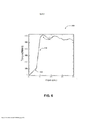
[0006] a Figura 6 ilustra uma curva de ângulo de torque-rotação da conexão telescópica;[0006] Figure 6 illustrates a torque-rotation angle curve of the telescopic connection;
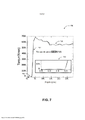
[0007] a Figura 7 ilustra uma curva de ângulo de torque - rotação ilustrativa do acoplamento de banda/eixo; e[0007] Figure 7 illustrates a torque angle curve - illustrative rotation of the band/shaft coupling; and
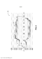
[0008] a Figura 8 ilustra perfis de torque ilustrativos para a curva de came de 2 degraus.[0008] Figure 8 illustrates illustrative torque profiles for the 2-step cam curve.
[0009] Com a proliferação das tecnologias de computação e rede, dispositivos de computação menores, portáteis e usáveis estão se tornando um lugar comum para o uso cotidiano pessoal e profissional. Os computadores tablet, smartphones, e phablets são exemplos de dispositivos que podem ser agarrados na orientação de retrato ou paisagem, ou que possam ser localizados em um desktop ou outra superfície plana e visualizado na orientação de retrato ou paisagem sem agarrar o dispositivo. Por exemplo, o dispositivo SURFACE® da MICROSOFT CORP. de Redmond, WA é um computador tablet que pode ser utilizado de forma similar a um computador laptop com um teclado conectável e um apoio integrado. Os usuários podem configurar o dispositivo em um ângulo em uma mesa utilizando o apoio e o tipo de teclado conectado. Dispositivos similares fazem uso de apoios para fornecer ângulos diferentes de visualização para usuários quando o tablet não é utilizado na mão.[0009] With the proliferation of computing and networking technologies, smaller, portable, wearable computing devices are becoming commonplace for everyday personal and professional use. Tablet computers, smartphones, and phablets are examples of devices that can be held in portrait or landscape orientation, or that can be located on a desktop or other flat surface and viewed in portrait or landscape orientation without holding the device. For example, the SURFACE® device from MICROSOFT CORP. from Redmond, WA is a tablet computer that can be used similarly to a laptop computer with a pluggable keyboard and integrated kickstand. Users can set up the device at an angle on a table using the stand and type of attached keyboard. Similar devices make use of grips to provide different viewing angles for users when the tablet is not held in the hand.
[0010] Apoios e mecanismos de suporte similares podem permitir um número limitado de ângulos de tela discretos. A oferta de ângulos de tela discretos pode limitar a experiência do usuário. Adicionalmente, apoios e dispositivos de suporte similares podem ser acoplados ao tablet que suportam através de uma articulação.[0010] Brackets and similar support mechanisms may allow a limited number of discrete screen angles. Offering discreet screen angles can limit the user experience. Additionally, pads and similar support devices can be attached to the tablet they support via a hinge.
[0011] De acordo com as implementações de apoio ilustrativas, um espaço substancialmente constante pode ser mantido entre o apoio e o alojamento de dispositivo através do espectro de rotação de articulação permitindo que a articulação e/ou apoio seja nivelada com o alojamento do dispositivo. O mecanismo de conexão pode suportar várias cargas de utilização e ângulos de rotação até cerca de 180 graus. De acordo com outras implementações ilustrativas, o mecanismo de conexão pode permitir uma abertura com baixa força para uma primeira posição enquanto compensa as sobrecargas acidentais e mantém o comportamento de suporte por toda a vida útil do desenho de um dispositivo de computação tipo tablet.[0011] According to the illustrative bearing implementations, a substantially constant gap can be maintained between the bearing and the device housing across the hinge rotation spectrum allowing the hinge and/or bearing to be flush with the device housing. The linkage mechanism can handle various usage loads and rotation angles up to about 180 degrees. In accordance with other illustrative implementations, the connection mechanism can allow low force opening to a first position while compensating for accidental overloads and maintaining support behavior throughout the design life of a tablet computing device.
[0012] Essas e outras características e vantagens serão aparentes a partir de uma leitura da descrição a seguir e uma revisão dos desenhos associados. Na descrição a seguir, referências são feitas aos desenhos em anexo que formam uma parte dos mesmos e onde são ilustradas por meio de ilustrações, as implementações específicas ou exemplos. Esses aspectos podem ser combinados, outros aspectos podem ser utilizados, e mudanças estruturais podem ser feitas sem se distanciar do espírito ou escopo da presente descrição. A descrição a seguir, portanto, não deve ser considerada responsável pela restrição dos aspectos como reivindicados.[0012] These and other features and advantages will be apparent from a reading of the following description and a review of the associated drawings. In the following description, references are made to the attached drawings which form a part thereof and where they are illustrated by means of illustrations, the specific implementations or examples. These aspects can be combined, other aspects can be used, and structural changes can be made without departing from the spirit or scope of the present description. The following description, therefore, should not be considered responsible for restricting the aspects as claimed.
[0013] Enquanto algumas implementações serão descritas no con texto geral do tablet ou dispositivos de computação de fator de forma similares, os aspectos também podem ser implementados em combinação com outros dispositivos e sistemas que podem ser suportados por um apoio ou dispositivo de suporte similar. Por exemplo, os quadros de imagem digital, televisões, e outros dispositivos que incluem um monitor podem empregar um apoio como descrito aqui.[0013] While some implementations will be described in the general context of tablet or similar form factor computing devices, aspects may also be implemented in combination with other devices and systems that may be supported by a support or similar support device. For example, digital picture frames, televisions, and other devices that include a monitor can employ a support as described here.
[0014] A Figura 1 ilustra duas vistas diferentes de um computador tablet com um apoio.[0014] Figure 1 illustrates two different views of a tablet computer with a support.
[0015] A vista 102 no diagrama 100 ilustra um computador de fator de forma de tablet com um apoio. O corpo 104 do computador é subs-tancialmente retangular com apoio 106 sendo acoplado ao corpo 104 ao longo de uma junção lateral. Para fornecer uma integração esteticamente agradável, o acoplamento do apoio 106 e do corpo 104 pode ser uma conexão nivelada, onde a articulação não se projeta a partir do plano de superfície traseira do corpo 104.[0015] View 102 in diagram 100 illustrates a tablet form factor computer with a stand.
[0016] A vista 110 do diagrama 100 é a vista lateral de um compu tador tablet similar juntamente com um teclado 118. O teclado 118 pode ser conectado ao corpo 114 do computador ao longo de sua borda inferior permanentemente ou temporariamente. O apoio 116 pode ser rotativo em ângulos predeterminados para permitir a configuração do computador tablet para vários ângulos de visualização.[0016] The
[0017] A capacidade de configurar o ângulo de tela pode ter uma influência substancial na experiência do usuário. Em um sistema de acordo com algumas implementações, o aumento do número de posições discretas disponíveis ou o fornecimento da capacidade de ajuste contínuo dentro de uma faixa desejada de rotação pode melhorar a experiência do usuário disponibilizando o ângulo de tela ideal para mais usuários em mais situações. Em outras implementações, uma articulação de fricção pode fornecer a conexão com a capacidade de fornecer 180 graus de rotação do apoio 116 enquanto mantém um espaço mínimo entre o apoio 116 e o corpo 114. Pela utilização da tecnologia de fricção de banda, a articulação de fricção pode ser capaz de alcançar torques suficientes para suportar cargas de uso e abuso e para manter essas cargas durante o ciclo de vida do computador.[0017] The ability to configure the screen angle can have a substantial influence on the user experience. In a system according to some implementations, increasing the number of discrete positions available or providing the ability to continuously adjust within a desired range of rotation can improve the user experience by making the ideal screen angle available to more users in more situations. . In other implementations, a friction linkage can provide the connection with the ability to provide 180 degrees of rotation of the
[0018] A Figura 2 ilustra uma vista aproximada da conexão entre o apoio e o computador tablet.[0018] Figure 2 illustrates a close-up view of the connection between the support and the tablet computer.
[0019] De acordo com a implementação ilustrativa ilustrada no di agrama 200, um ponto de articulação 206 do acoplamento de corpo de apoio permite a rotação de 180 graus enquanto mantém um espaço y substancialmente constante entre o apoio 204 e o corpo 202. Uma articulação de fricção pode ser capaz de fornecer os 180 graus de rotação enquanto mantém um espaço mínimo. Pela utilização da tecnologia de fricção de banda, a articulação de fricção pode ser capaz de alcançar os torques suficientes para suportar as cargas de uso e abuso e manter essas cargas por toda a vida útil do produto. Adicionalmente, a capacidade em chegar a 180 graus pode fornecer o manuseio de carga excessiva sem exibir um mecanismo adicional ou maior complexidade (isto é, o apoio pode simplesmente girar para uma posição extrema quando uma pressão inesperada é aplicada ao corpo).[0019] According to the illustrative implementation illustrated in diagram 200, a
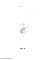
[0020] As Figuras 3A a 3E ilustram um mecanismo de conexão ilustrativo que inclui acoplamento de fricção e conexão telescópica em ângulos de rotação diferentes.[0020] Figures 3A to 3E illustrate an illustrative connection mechanism that includes friction coupling and telescopic connection at different angles of rotation.
[0021] Nas Figuras 3A a 3E, a conexão telescópica é ilustrada acoplada ao eixo. Esse é um exemplo ilustrativo e não implica uma limitação das implementações. A conexão telescópica também pode ser acoplada a um núcleo de fricção, que pode ser uma banda de fric- ção, um disco de fricção ou um clipe de fricção. A fricção de banda e a fricção de clip podem ser similares visto que ambos aplicam pressão de forma circunferencial em torno do eixo. A fricção de disco pode aplicar fricção axialmente em um círculo em torno de um eixo. Dessa forma, a fricção de disco pode ter uma densidade de torque ligeiramente menor, mas pode adicionar uma capacidade de programação adicional à curva de torque. No caso de fricção de disco, a fricção pode ser em torno de um eixo, mas a força é aplicada na direção axial. Adicionalmente, o núcleo de fricção pode ser singular, ou (frequentemente) bandas, clipes e discos podem ser empregados em múltiplos de cada vez.[0021] In Figures 3A to 3E, the telescopic connection is illustrated coupled to the shaft. This is an illustrative example and does not imply a limitation on implementations. The telescoping connection can also be attached to a friction core, which can be a friction band, friction disc or friction clip. Band friction and clip friction can be similar as they both apply pressure circumferentially around the shaft. Disc friction can apply friction axially in a circle around an axis. In this way, disk friction can have a slightly lower torque density, but can add additional programmability to the torque curve. In the case of disk friction, the friction can be around an axis, but the force is applied in the axial direction. Additionally, the friction core can be singular, or (often) bands, clips and discs can be employed in multiples at a time.
[0022] O diagrama 310 na Figura 3A ilustra os componentes de um acoplamento de banda/eixo que pode ser empregado em algumas implementações. O torque de fricção rotativo é fornecido pelo eixo 311 e a banda 312 cercando substancialmente o eixo 311. Uma conexão telescópica 316 fixada ao eixo 311 e encerrada parcialmente pela conexão âncora 318 pode permitir o acoplamento por fricção em um eixo geométrico secundário. A banda 312 pode ser fixada à conexão de apoio 314.[0022] Diagram 310 in Figure 3A illustrates the components of a band/shaft coupling that may be employed in some implementations. Rotary frictional torque is provided by
[0023] A manutenção de um espaço substancialmente constante entre o apoio e o corpo em todos os ângulos de articulação, suporte de cargas de utilização, suporte da rotação máxima (180 graus), abertura de baixa força para uma primeira posição, e/ou suporte para carga excessiva acidental podem ser alcançados através do uso do acoplamento de fricção em um eixo geométrico secundário para induzir um impulso puro para o apoio em todos os ângulos de apoio. A fim de restringir a fricção, a conexão telescópica pode reagir contra o impulso e acoplar o elemento de fricção ao aterramento mecânico.[0023] The maintenance of a substantially constant space between the support and the body at all angles of articulation, support of use loads, support of maximum rotation (180 degrees), low force opening for a first position, and/or Accidental overload support can be achieved by using friction coupling on a secondary geometry axis to induce a pure thrust to the support at all support angles. In order to restrict friction, the telescopic connection can react against the thrust and couple the friction element to the mechanical ground.
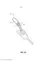
[0024] O diagrama 320 da Figura 3B ilustra a configuração de arti culação de acoplamento por fricção do diagrama 310 em um ângulo de rotação diferente. A combinação de banda/eixo pode ser formada utilizando-se a tecnologia de moldagem por injeção de metal ("MIM"). A tecnologia MIM pode permitir a criação de um acessório pequeno, que, por sua vez, por permitir diferentes perfis de came (por exemplo, para combinação de peso) que podem, de outra forma, não estar disponíveis em abordagens de fricção de banda ou clipe. Adicionalmente, com a tecnologia MIM, aço de alta resistência pode ser moldado, o que pode permitir uma maior densidade de torque (ou partes menores) e pode ser menos restringido pelos processos de fabricação (visto que a fricção de banda e clipe é submetida a limitações de processamento de metal laminado e outros). O material MIM também pode permitir o gerenciamento do formato de banda de modo que o material seja otimizado para uma energia de tensão máxima por toda a parte, alcançando, assim, a máxima densidade de torque.[0024] Diagram 320 of Figure 3B illustrates the friction coupling pivot configuration of diagram 310 at a different angle of rotation. The band/shaft combination can be formed using metal injection molding ("MIM") technology. MIM technology can allow the creation of a small fitting, which in turn can allow for different cam profiles (e.g. for weight matching) that may otherwise not be available in band friction approaches or clip. Additionally, with MIM technology, high-strength steel can be cast, which can allow for greater torque density (or smaller parts) and can be less constrained by manufacturing processes (as band and clip friction is subjected to laminated metal processing limitations and others). The MIM material can also allow management of the band shape so that the material is optimized for maximum stress energy throughout, thus achieving maximum torque density.
[0025] Em uma parte MIM, pode ser difícil se equilibrar a resistên cia com ductilidade. Isso é, quando a parte é dúctil o suficiente para ter uma boa resistência à fratura, o material pode ser muito macio e pode desgastar rapidamente. Quando a parte é dura o suficiente para resistir ao desgaste, a mesma pode ser submetida à fratura. A resistência ao desgaste pode ser desacoplada da ductilidade de acordo com algumas implementações pela incorporação de uma placa de desgaste (discutida na Figura 3E abaixo) na banda que pode ser muito dura (por exemplo, HRC 50+) e que gerencia o desgaste das partes. A banda pode ser reduzida para HRC35, por exemplo, a fim de ter ductilidade suficiente para resistir à fratura.[0025] In a MIM part, it can be difficult to balance strength with ductility. That is, when the part is ductile enough to have good fracture toughness, the material can be very soft and can wear out quickly. When the part is hard enough to resist wear and tear, it can be subjected to fracture. Wear resistance can be decoupled from ductility according to some implementations by incorporating a wear plate (discussed in Figure 3E below) in the band which can be very hard (e.g. HRC 50+) and which manages wear of the parts . The band can be reduced to HRC35, for example, in order to have enough ductility to resist fracture.
[0026] O diagrama 330 da Figura 3C é uma ilustração de capaci dades adicionais que podem ser introduzidas utilizando-se uma combinação de acoplamento de eixo e banda de conexão telescópica de acordo com algumas implementações. Por exemplo, os entalhes 331 perto de uma extremidade da conexão telescópica 336 podem forne- cer pequenos espaços livres. No começo da rotação (por exemplo, de 5 a 10 graus) do apoio, o usuário pode não sofrer de torque devido aos entalhes visto que a conexão telescópica é empurrada para dentro do link âncora 338 permitindo que o usuário insira seu dedo entre o apoio e o corpo com facilidade.[0026] Diagram 330 of Figure 3C is an illustration of additional capabilities that can be introduced using a combination of shaft coupling and telescopic connection band according to some implementations. For example, the
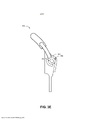
[0027] O diagrama 340 da Figura 3D é outra vista de ângulo de ro tação da configuração de articulação de acoplamento por fricção do diagrama 310. Em implementações adicionais, a fricção adicional pode ser introduzida na conexão telescópica pela seleção de materiais adequados, dimensões, ou utilizando materiais adicionais (por exemplo, forro dentro da conexão âncora com um material de fricção maior). A fricção total do sistema é a soma da fricção de seus componentes. Dessa forma, a fricção necessária no acoplamento de banda/eixo pode ser reduzida pela introdução da fricção adicional na conexão telescópica. Em outras implementações, a fricção em outros componentes do sistema pode ser reduzida de modo que a fricção do acoplamento de banda/eixo seja a fonte dominante de fricção, e a consistência através da vida útil da articulação pode ser alcançada.[0027] Diagram 340 of Figure 3D is another rotation angle view of the friction coupling pivot configuration of diagram 310. In further implementations, additional friction can be introduced into the telescoping connection by selecting suitable materials, dimensions, or using additional materials (eg lining inside the anchor connection with a higher friction material). The total friction of the system is the sum of the friction of its components. In this way, the friction required in the band/shaft coupling can be reduced by introducing additional friction into the telescoping connection. In other implementations, friction in other components of the system can be reduced so that band/shaft coupling friction is the dominant source of friction, and consistency through the life of the linkage can be achieved.
[0028] O diagrama 360 da Figura 3E ilustra uma placa de desgas te 366 incorporada à estrutura de banda/eixo compreendendo a banda 364 e o eixo 362. Como discutido acima, a resistência ao desgaste pode ser desacoplada da ductilidade de acordo com algumas implementações pela incorporação da placa de desgaste 366 que gerencia o desgaste das partes. A placa de desgaste pode ser mantida no lugar pela inserção do eixo 362. Um acoplamento de encaixe justo, uma junta tipo rabo de andorinha, ou mecanismos de acoplamento similares podem ser empregados para manter a placa de desgaste 366 no lugar. A placa de desgaste 366 também pode ser mantida por um encaixe de interferência, cola, solda, etc.[0028] Diagram 360 of Figure 3E illustrates a
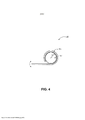
[0029] A Figura 4 ilustra um acoplamento de banda/eixo ilustrativo.[0029] Figure 4 illustrates an illustrative band/shaft coupling.
[0030] O diagrama 400 ilustra um acoplamento de banda/eixo cir cular básico com um eixo 404 do diâmetro d e uma banda 402 cercando substancialmente o eixo 404. Em sistemas com base em metal laminado, a densidade de torque é limitada para o dobro da espessura do material para um diâmetro determinado do eixo 404. Dessa forma, os computadores tablet mais finos podem não ser capazes de serem projetados com densidade de torque desejada utilizando acoplamento de banda/eixo com base em metal laminado. Um sistema de acordo com algumas implementações pode ser capaz de fornecer a densidade de torque desejada e outros aspectos de desenho discutidos acima pela utilização de conexão telescópica e perfis de eixo não circular.[0030] Diagram 400 illustrates a basic circular band/shaft coupling with a
[0031] As Figuras 5A a 5D ilustram vários exemplos de um aco plamento de eixo/banda de moldagem por injeção de metal que pode ser utilizado para diferentes implementações[0031] Figures 5A to 5D illustrate several examples of a metal injection molding shaft/band coupling that can be used for different implementations
[0032] O acoplamento de eixo/banda ilustrativo na Figura 5A inclui um eixo substancialmente elíptico 405 em oposição a um circular fornecendo um perfil de torque crescente à medida que os braços da banda 502 são empurrados para longe um do outro de forma diferente enquanto o eixo está girando. O espaço 506 entre os braços da banda 502 também pode ser localizado em locais diferentes (por exemplo, localização 508 ou 510) selecionando a localização de um mergulho na curva de torque, determinando, assim, em que ângulos de rotação o usuário pode mover o apoio com pouca ou nenhuma força. Deve-se notar que essa articulação ilustrativa pode ter uma banda que não possui uma abertura. Pode ter uma alça contínua e a conformidade pode ser criada pelos espaços entre o eixo elíptico e a banda circular. O formato pode ser projetado de modo que o eixo possa ter arcos cir-culares que combinam com o formato de banda na interface de fricção e os lados do perfil de eixo que não tocam o eixo podem ser projetados para otimizar a conformidade e a superfície de contato.[0032] The illustrative shaft/band coupling in Figure 5A includes a substantially elliptical shaft 405 as opposed to a circular one providing an increasing torque profile as the
[0033] O eixo 514 na Figura 5B possui um perfil que é essencial mente uma combinação de dois círculos concêntricos (diâmetros d1 e d2). Os círculos concêntricos podem definir um perfil de came onde raios são selecionados para configurar o torque em uma região angular particular. Isso pode exigir uma geometria complementar (não combinando) na banda. Em algumas implementações, uma parte plana na banda pode ser utilizada, que pode permitir que os raios no eixo funcionem adequadamente. Em outras implementações, a seção transversal da banda pode ser perfilada para otimizar a energia de tensão na banda. Por exemplo, círculos excêntricos podem ser utilizados. Dessa forma, a seção transversal da banda pode ser sintonizada para otimizar o uso do material para alcançar a energia de tensão máxima do material e, dessa forma, a densidade de torque mais alta. Em algumas implementações dos círculos concêntricos, os centros dos dois círculos podem divergir. À medida que o centro diverge, a energia de tensão da banda 512 pode ser utilizada de forma mais eficiente.[0033] The
[0034] Em ainda outras implementações, a curva de came pode ser feita para combinar com o perfil de peso do apoio. Pode haver um formado ou "perfil" para ambos a banda (ou prendedor ou pilha de disco) e o eixo a fim de criar o perfil de torque sintonizado ou programado. Em algumas implementações, onde o perfil de peso é combinado, o perfil pode seguir uma equação para uma linha em coordenadas polares, por exemplo, R = mq + b; onde R é o raio de perfil em um determinado q, m é a taxa de mudança do raio e b é o raio inicial. Em outra implementação ilustrativa, o eixo 524 na Figura 5C pode ter um perfil de combinação. A primeira parte pode ser um círculo (substancialmente a metade esquerda do eixo) com um raio constante d1, en-quanto a parte pode ter um segundo raio d2. A parte pode ser projetada de modo que seu raio mude de d1 para d2 pelo aumento linear ou não linear. Em uma alternativa, o raio pode aumentar subitamente de d1 para d2. Um aumento linear de d1 para d2 pode fornecer um torque inicialmente constante seguido por um perfil de torque crescente visto que a energia de tensão crescente da banda 522, devido à parte de raio crescente do eixo 524, empurra a banda 522 para longe. O componente de queda 525 pode ser utilizado para definir onde a rotação termina.[0034] In still other implementations, the cam curve can be made to match the weight profile of the support. There may be a shape or "profile" for both the band (or fastener or disc stack) and the shaft in order to create the tuned or programmed torque profile. In some implementations, where the weight profile is combined, the profile may follow an equation for a line in polar coordinates, for example, R = mq + b; where R is the profile radius at a given q, m is the rate of change of the radius, and b is the initial radius. In another illustrative implementation,
[0035] O eixo ilustrativo 528 na Figura 5D possui um perfil poligo nal que permite que o apoio tenha posições de entalhe. Pela seleção do polígono (por exemplo, hexágono, octógono, etc.), várias posições de entalhe desejadas podem ser configuradas. Em outras implementações, as combinações dos perfis discutidos acima e outros podem ser utilizadas. Por exemplo, um perfil poligonal pode ser combinado com o perfil de rádio crescente de forma constante resultando em um perfil de torque que aumenta de uma posição de entalhe para outra.[0035] The
[0036] Em ainda outras implementações adicionais, uma estrutura de alavanca de quebra pode ser utilizada em conjunto com a estrutura de eixo/banda permitindo um coeficiente de fricção maior e um torque maior quando o apoio está abrindo e um torque menor quando o apoio está fechado. Em algumas implementações, uma parte de freio de borracha pode ser utilizada onde um ou mais componentes de articulação podem ser intercalados entre duas partes flexíveis ou semiflexíveis, e as partes podem ser pressionadas uma contra a outra através de um mecanismo de pressão ajustável (por exemplo, um parafuso) de modo que um coeficiente de fricção possa ser configurado para um valor desejado.[0036] In still other additional implementations, a breaking lever structure can be used in conjunction with the shaft/band structure allowing a greater coefficient of friction and a greater torque when the support is opening and a smaller torque when the support is closed. In some implementations, a rubber stopper part may be used where one or more hinge members can be sandwiched between two flexible or semi-flexible parts, and the parts can be pressed against each other through an adjustable pressure mechanism (e.g. , a screw) so that a coefficient of friction can be set to a desired value.
[0037] Os exemplos nas Figuras 1 a 5 foram descritos com com ponentes, perfis e configurações específicas. As implementações não estão limitadas aos sistemas de acordo com essas configurações ilustrativas. Uma articulação de fricção para computadores tablet e dispositivos similares pode ser implementada em configurações utilizando outros tipos de acoplamentos utilizando os princípios descritos aqui.[0037] The examples in Figures 1 to 5 were described with components, profiles and specific configurations. Implementations are not limited to systems according to these illustrative configurations. A friction joint for tablet computers and similar devices can be implemented in configurations using other types of couplings using the principles described here.
[0038] A Figura 6 ilustra uma curva de ângulo de rotação - torque ilustrativa da conexão telescópica.[0038] Figure 6 illustrates a curve of rotation angle - torque illustrating the telescopic connection.
[0039] O diagrama 600 ilustra o aumento linear no torque 602 para os primeiros poucos graus de rotação, seguido por um aumento linear mais pronunciado 604 até que um valor de torque de pico seja alcançado 606 e o torque permaneça substancialmente constante ou caia ligeiramente à medida que a rotação continua. O desafio com esse tipo de curva de torque é que o usuário experimenta a necessidade de se fornecer uma força crescente à medida que abre primeiramente o apoio mesmo pelos primeiros poucos graus. Quando o usuário começa a abrir o apoio, o usuário pode não ter um agarre sólido no apoio. Um componente de agarre especialmente formado, tal como uma saliência ou alça, pode aliviar esse efeito solicitando que o usuário agarre com firmeza o apoio depois de iniciar a abertura do apoio.[0039] Diagram 600 illustrates the linear increase in
[0040] A Figura 7 ilustra uma curva de ângulo de rotação - torque ilustrativa do acoplamento de banda/eixo.[0040] Figure 7 illustrates a curve of rotation angle - torque illustrating the band/shaft coupling.
[0041] A curva de torque de um acoplamento de banda/eixo no di agrama 700 inclui uma zona de torque substancialmente igual a zero 702 no começo da rotação ilustrado em detalhes na vista aproximada. Dessa forma, um apoio com uma curva de torque similar a uma ilustrada no diagrama 700 pode permitir que um usuário abra o apoio sem força considerável. Por exemplo, o usuário pode precisar apenas fornecer menos que 5 Nmm de torque para abrir o apoio. Seguindo a zona de baixo torque, uma parte de aumento pronunciado 704 da curva de torque pode garantir um torque substancialmente constante 706 que pode ser fornecido através do restante da rotação apesar de um pico pequeno poder ocorrer no começo.[0041] The torque curve of a band/shaft coupling in diagram 700 includes a substantially zero
[0042] A Figura 8 ilustra perfis de torque ilustrativos para a curva de came de duas etapas.[0042] Figure 8 illustrates illustrative torque profiles for the two-step cam curve.
[0043] Como discutido acima em conjunto com a Figura 5D, os vá- rios eixos de perfil ou estruturas comparáveis podem ser empregados para criar posições de entalhe e/ou perfis de torque diferentes. O diagrama 800 ilustra uma curva de torque de 2 etapas, onde o acoplamento de banda/eixo juntamente com uma conexão telescópica pode permitir que três torques distintos sejam experimentados pelo usuário à medida que o apoio é girado. Para os primeiros poucos graus (zona de abertura 802), um torque substancialmente igual a zero pode ser alcançado através de um mecanismo tal como nos entalhes discutidos acima. Isso pode ser seguido pela primeira zona de torque substancialmente constante 806.[0043] As discussed above in conjunction with Figure 5D, various profile shafts or comparable structures can be employed to create different notch positions and/or torque profiles. Diagram 800 illustrates a 2-step torque curve, where band/shaft coupling together with a telescoping connection can allow three distinct torques to be experienced by the user as the support is rotated. For the first few degrees (gap zone 802), a substantially zero torque can be achieved through a mechanism such as the notches discussed above. This may be followed by the first substantially
[0044] A primeira zona de torque substancialmente constante 804 pode permitir que o usuário abra o apoio com mais facilidade até 45 graus. A faixa de 0 a 45 graus para o apoio pode cobrir posições típicas para o apoio quando o usuário deseja exibir o computador tablet em uma posição reta. Depois das posições típicas, mais torque pode ser aplicado para evitar a abertura acidental do apoio todo o caminho (por exemplo, abertura para 180 graus). O usuário pode desejar abrir o apoio para, por exemplo, por 140 graus para fornecer uma superfície angulada obtusa que é otimizada para escrever em um tablet com uma caneta ou outro dispositivo de entrada. Exigindo mais torque para abrir o apoio além de 140 graus pode impedir vantajosamente que o apoio abra ainda quando o usuário aplica uma força descendente no tablet à medida que escreve na superfície de tablet. Um perfil de torque aumentado em um segundo ou terceiro estágios pode ser utilizado para indicar para o usuário que a zona de utilização típica foi excedida. Ainda, em outras implementações, o torque apresentado para graus superiores de rotação pode ser inferior ao torque para a zona inicial (por exemplo, os primeiros 45 graus) visto que o usuário pode esperar aplicar menos força para graus superiores de rotação.[0044] The first zone of substantially
[0045] Em ainda outras implementações, um perfil de torque assi- métrico pode ser fornecido onde menos torque pode ser apresentado para fechar o apoio em comparação com a abertura. Dessa forma, o usuário pode ser capaz de fechar o apoio com menos força do que a utilizada para abrir o mesmo.[0045] In still other implementations, an asymmetrical torque profile can be provided where less torque can be presented to close the support compared to opening. In this way, the user may be able to close the support with less force than the one used to open it.
[0046] De acordo com algumas implementações ilustrativas, uma articulação por fricção é descrita e inclui uma estrutura de banda/eixo com um eixo de fricção e uma banda de fricção que é configurada para cercar substancialmente o eixo de fricção, e uma estrutura de conexão telescópica que inclui uma conexão telescópica fixada ao eixo de fricção e uma conexão de âncora que é configurada para cercar pelo menos parcialmente a conexão telescópica.[0046] According to some illustrative implementations, a friction joint is described and includes a band/shaft structure with a friction axis and a friction band that is configured to substantially surround the friction axis, and a connecting structure telescoping that includes a telescoping connection attached to the friction shaft and an anchor connection that is configured to at least partially surround the telescoping connection.
[0047] A banda de fricção pode ser configurada para ser fixada a um primeiro componente e a conexão de âncora pode ser configurada para ser fixada a um segundo componente, a articulação de fricção permitindo o acoplamento rotativo entre o primeiro e o segundo componentes enquanto mantém um espaço substancialmente constante entre o primeiro e o segundo componentes durante a rotação. A articulação de fricção também pode incluir um ou mais entalhes formados perto de uma extremidade da conexão telescópica de modo que um torque substancialmente igual a zero seja fornecido durante uma parte inicial de rotação do primeiro e segundo componentes. A conexão telescópica e a conexão de âncora podem ser selecionadas para fornecer a fricção adicional para a articulação de fricção.[0047] The friction band can be configured to be attached to a first component and the anchor connection can be configured to be attached to a second component, the friction joint allowing rotational coupling between the first and second components while maintaining a substantially constant gap between the first and second components during rotation. The friction linkage may also include one or more notches formed near one end of the telescoping connection so that substantially zero torque is provided during an initial portion of rotation of the first and second components. Telescoping connection and anchor connection can be selected to provide additional friction for the friction joint.
[0048] A fricção adicional pode ser fornecida através de uma ou mais dentre uma seleção de dimensões da conexão telescópica e a conexão de âncora, uma seleção de materiais para a conexão telescópica e a conexão de âncora, e uma aplicação de material controlável por fricção a uma superfície de pelo menos um dentre a conexão telescópica e a conexão de âncora. A fricção adicional pode ser minimizada de modo que a fricção fornecida pela estrutura de banda/eixo se- ja dominante ou selecionada para complementar a fricção fornecida pela estrutura de banda/eixo.[0048] The additional friction can be provided through one or more of a selection of dimensions of the telescopic connection and the anchor connection, a selection of materials for the telescopic connection and the anchor connection, and an application of friction controllable material to a surface of at least one of the telescopic connection and the anchor connection. Additional friction can be minimized so that the friction provided by the tread/shaft structure is dominant or selected to complement the friction provided by the tread/shaft structure.
[0049] Um perfil do eixo de fricção pode ser selecionado de modo que um perfil de peso do primeiro componente seja combinado subs-tancialmente. Um perfil do eixo de fricção pode ser selecionado de modo que um perfil de torque assimétrico seja fornecido com menos torque sendo apresentado à medida que o primeiro e o segundo componentes são girados na direção um do outro em comparação com um torque sendo apresentado à medida que o primeiro e o segundo componentes são girados para longe um do outro. A estrutura de banda/eixo pode ser formada utilizando moldagem por injeção de metal (MIM).[0049] A friction axis profile can be selected so that a weight profile of the first component is substantially matched. A friction shaft profile can be selected such that an asymmetrical torque profile is provided with less torque being introduced as the first and second components are rotated towards each other compared to a torque being presented as the first and second components are rotated away from each other. The band/shaft structure can be formed using metal injection molding (MIM).
[0050] De acordo com outras implementações ilustrativas, uma ar ticulação por fricção para acoplamento de um apoio e um dispositivo de computação pode incluir uma estrutura de banda/eixo com um eixo de fricção e uma banda de fricção que é configurada para cercar substancialmente o eixo de fricção; e uma estrutura de conexão telescópica que inclui uma conexão telescópica fixada ao eixo de fricção e uma conexão de âncora que é configurada para cercar pelo menos parcialmente a conexão telescópica, onde a banda de fricção é configurada para ser fixada ao apoio e a conexão de âncora é configurada para ser fixada a um corpo do dispositivo de computação, a articulação de fricção permitindo o acoplamento rotativo entre o apoio e o corpo enquanto mantém um espaço substancialmente constante entre o apoio e o corpo durante a rotação do apoio.[0050] According to other illustrative implementations, a friction joint for coupling a support and a computing device may include a band/axis structure with a friction axis and a friction band that is configured to substantially surround the friction shaft; and a telescopic connection structure including a telescopic connection attached to the friction shaft and an anchor connection that is configured to at least partially surround the telescopic connection, where the friction band is configured to be attached to the support and the anchor connection is configured to be attached to a body of the computing device, the friction hinge allowing rotational engagement between the mount and the body while maintaining a substantially constant gap between the mount and the body during rotation of the mount.
[0051] O eixo de fricção pode ter um perfil substancialmente elípti co. Uma localização de um espaço na banda de fricção pode ser selecionada com base em um mergulho desejado em uma curva de ângu- lo-torque de rotação da articulação de fricção. A articulação de fricção pode incluir ainda uma estrutura de alavanca de freio configurada para fornecer a fricção aumentada e um torque assimétrico à medida que o apoio abre e fecha. A articulação de fricção também pode incluir uma estrutura de parte de freio configurada para comprimir um ou mais componentes da articulação de fricção através de um mecanismo de pressão ajustável para fornecer o torque aumentado à medida que o apoio é girado. Formatos do eixo de fricção e dimensões da estrutura de conexão telescópica podem ser selecionados para fornecer um perfil de torque de múltiplas etapas através de um espectro de rotação do apoio. Por exemplo, a estrutura pode ter um raio menor no eixo e uma superfície plana na banda, apesar de isso poder ser realizado com outros perfis de banda/eixo. Em ângulos onde o raio menor está em contato com a superfície plana, o torque pode ser inferior visto que a ban-da é menos deformada. Em ângulos onde o raio principal está contra o plano, o torque pode ser superior visto que a banda é mais deformada.[0051] The friction axis may have a substantially elliptical profile. A friction band gap location can be selected based on a desired dip in a friction linkage rotation angle-torque curve. The friction linkage can further include a brake lever structure configured to provide increased friction and asymmetrical torque as the strut opens and closes. The friction linkage may also include a brake part structure configured to compress one or more components of the friction linkage through an adjustable pressure mechanism to provide increased torque as the bearing is rotated. Friction shaft shapes and telescoping connection frame dimensions can be selected to provide a multi-step torque profile across a bearing rotation spectrum. For example, the structure can have a smaller radius on the shaft and a flat surface on the web, although this can be achieved with other web/shaft profiles. At angles where the smaller radius is in contact with the flat surface, the torque can be lower as the web is less deformed. At angles where the main radius is against the plane, the torque can be higher as the web is deformed more.
[0052] De acordo com as implementações ilustrativas adicionais, uma estrutura de suporte rotativa para um dispositivo tablet pode incluir um apoio configurado para suportar o dispositivo tablet em uma pluralidade de ângulos; uma estrutura de banda/eixo que inclui um eixo de fricção e uma banda de fricção que é configurada para cercar substancialmente o eixo de fricção, e uma estrutura de conexão telescópica que inclui uma conexão telescópica fixada ao eixo de fricção e uma conexão de âncora que é configurada para cercar pelo menos parcialmente a conexão telescópica, onde a banda de fricção é configurada para ser fixada ao apoio e a conexão de âncora é configurada para ser fixada a um corpo do dispositivo tablet, a articulação de fricção permitindo o acoplamento rotativo entre o apoio e o corpo enquanto mantém um espaço substancialmente constante entre o apoio e o corpo durante a rotação do apoio.[0052] In accordance with further illustrative implementations, a rotatable support structure for a tablet device may include a support configured to support the tablet device at a plurality of angles; a band/shaft structure that includes a friction shaft and a friction band that is configured to substantially surround the friction shaft, and a telescopic connection structure that includes a telescoping connection attached to the friction shaft and an anchor connection that is configured to at least partially surround the telescoping connection, where the friction band is configured to be attached to the backing and the anchor connection is configured to be attached to a body of the tablet device, the friction hinge allowing rotary coupling between the support and the body while maintaining a substantially constant space between the support and the body during rotation of the support.
[0053] O eixo de fricção pode ter um perfil que inclui dois círculos substancialmente concêntricos com diâmetros distintos, pelo menos um dos diâmetros sendo selecionado com base em um torque deseja- do a ser apresentado à medida que o apoio é girado. O eixo de fricção pode ter um perfil poligonal com um número de lados do polígono sendo selecionado com base em um número de posições de entalhe para o apoio. O eixo de fricção também pode ter um perfil com uma combinação de um primeiro círculo de diâmetro substancialmente constante e um segundo círculo de diâmetro crescente para fornecer um perfil de torque que inclui uma parte de torque constante e uma parte de torque crescente através de um espectro de rotação do apoio. O eixo de fricção pode ter um perfil adicional que inclui uma combinação de um primeiro polígono de diâmetro substancialmente constante e um segundo polígono de diâmetro crescente para fornecer um perfil de torque que inclui uma parte de torque constante e uma parte de torque crescente através de um espectro de rotação do apoio com posições de entalhe.[0053] The friction shaft can have a profile that includes two substantially concentric circles with different diameters, at least one of the diameters being selected based on a desired torque to be presented as the support is rotated. The friction shaft can have a polygonal profile with a number of polygon sides being selected based on a number of notch positions for the support. The friction shaft may also be profiled with a combination of a first circle of substantially constant diameter and a second circle of increasing diameter to provide a torque profile that includes a constant torque portion and an increasing torque portion across a spectrum. support rotation. The friction shaft may have an additional profile that includes a combination of a first polygon of substantially constant diameter and a second polygon of increasing diameter to provide a torque profile that includes a constant torque portion and an increasing torque portion through a support rotation spectrum with notch positions.
[0054] A especificação, os exemplos e os dados acima fornecem uma descrição completa de fabricação e utilização da composição das modalidades. Apesar de a presente matéria ter sido descrita em linguagem específica para características estruturais e/ou atos metodológicos, deve-se compreender que a presente matéria definida nas reivindicações em anexo não é necessariamente limitada às características ou atos específicos descritos acima. Em vez disso, as características e atos específicos descritos acima são descritos como formas ilustrativas de implementação das reivindicações e modalidades.[0054] The above specification, examples, and data provide a complete description of fabrication and use of composition modalities. Although the present matter has been described in language specific to structural features and/or methodological acts, it should be understood that the present matter defined in the appended claims is not necessarily limited to the specific features or acts described above. Rather, the specific features and acts described above are described as illustrative ways of implementing the claims and embodiments.
Claims (18)
Applications Claiming Priority (3)
| Application Number | Priority Date | Filing Date | Title |
|---|---|---|---|
| US14/281,905 | 2014-05-20 | ||
| US14/281,905 US9549479B2 (en) | 2014-05-20 | 2014-05-20 | Friction hinge for tablet computers |
| PCT/US2015/031271 WO2015179257A1 (en) | 2014-05-20 | 2015-05-16 | Friction hinge for tablet computers |
Publications (3)
| Publication Number | Publication Date |
|---|---|
| BR112016026241A2 BR112016026241A2 (en) | 2017-08-15 |
| BR112016026241A8 BR112016026241A8 (en) | 2021-06-15 |
| BR112016026241B1 true BR112016026241B1 (en) | 2022-11-08 |
Family
ID=53404849
Family Applications (1)
| Application Number | Title | Priority Date | Filing Date |
|---|---|---|---|
| BR112016026241-7A BR112016026241B1 (en) | 2014-05-20 | 2015-05-16 | FRICTION JOINT AND ROTATING SUPPORT STRUCTURE FOR TABLET COMPUTERS |
Country Status (19)
| Country | Link |
|---|---|
| US (1) | US9549479B2 (en) |
| EP (1) | EP3146404A1 (en) |
| JP (1) | JP6594344B2 (en) |
| KR (1) | KR102383587B1 (en) |
| CN (1) | CN106462189B (en) |
| AU (1) | AU2015264457B2 (en) |
| BR (1) | BR112016026241B1 (en) |
| CA (1) | CA2947039C (en) |
| CL (1) | CL2016002936A1 (en) |
| HK (1) | HK1232316A1 (en) |
| IL (1) | IL248813B (en) |
| MX (1) | MX2016014984A (en) |
| MY (1) | MY183254A (en) |
| NZ (1) | NZ725806A (en) |
| PH (1) | PH12016502030A1 (en) |
| RU (1) | RU2685987C2 (en) |
| SG (1) | SG11201609533SA (en) |
| WO (1) | WO2015179257A1 (en) |
| ZA (1) | ZA201606708B (en) |
Families Citing this family (35)
| Publication number | Priority date | Publication date | Assignee | Title |
|---|---|---|---|---|
| CN104937518B (en) * | 2013-03-14 | 2018-09-11 | 惠普发展公司,有限责任合伙企业 | Electronic display system with supporting rack |
| US9447620B2 (en) | 2014-09-30 | 2016-09-20 | Microsoft Technology Licensing, Llc | Hinge mechanism with multiple preset positions |
| US9752361B2 (en) | 2015-06-18 | 2017-09-05 | Microsoft Technology Licensing, Llc | Multistage hinge |
| US9769942B2 (en) * | 2015-06-25 | 2017-09-19 | Frederick Longo | Retractable display assembly |
| JP1557075S (en) * | 2015-11-09 | 2016-08-29 | ||
| US10227808B2 (en) | 2015-11-20 | 2019-03-12 | Microsoft Technology Licensing, Llc | Hinged device |
| US10358853B2 (en) | 2016-04-07 | 2019-07-23 | Microsoft Technology Licensing, Llc | Friction hinge |
| US9557776B1 (en) * | 2016-05-10 | 2017-01-31 | Zagg Intellectual Property Holding Co., Inc. | Friction resistance hinge with auto-lock |
| US10474203B2 (en) | 2016-09-01 | 2019-11-12 | Microsoft Technology Licensing, Llc | Hinged device |
| US10364598B2 (en) | 2016-09-02 | 2019-07-30 | Microsoft Technology Licensing, Llc | Hinged device |
| US10037057B2 (en) | 2016-09-22 | 2018-07-31 | Microsoft Technology Licensing, Llc | Friction hinge |
| US10066429B2 (en) | 2016-10-26 | 2018-09-04 | Microsoft Technology Licensing, Llc | Hinge with minimized free play |
| TWM538308U (en) * | 2016-11-17 | 2017-03-11 | First Dome Corp | Thin hinge |
| US10241548B2 (en) | 2016-12-09 | 2019-03-26 | Microsoft Technology Licensing, Llc | Computing device employing a self-spacing hinge assembly |
| US10641318B2 (en) | 2016-12-09 | 2020-05-05 | Microsoft Technology Licensing, Llc | Hinged device |
| US10871016B2 (en) | 2017-01-17 | 2020-12-22 | Huawei Technologies Co., Ltd. | Protective case for tablet computer and two-in-one computer |
| US10253804B2 (en) | 2017-01-24 | 2019-04-09 | Microsoft Technology Licensing, Llc | Hinged device |
| TWI616599B (en) * | 2017-05-18 | 2018-03-01 | 宏碁股份有限公司 | Hinge structure |
| US10228732B2 (en) | 2017-05-19 | 2019-03-12 | Microsoft Technology Licensing, Llc | Hinge with variable sliding friction |
| US10296044B2 (en) | 2017-06-08 | 2019-05-21 | Microsoft Technology Licensing, Llc | Hinged device |
| US10344510B2 (en) | 2017-06-16 | 2019-07-09 | Microsoft Technology Licensing, Llc | Hinged device |
| EP3645815A4 (en) * | 2017-06-26 | 2021-01-13 | Hewlett-Packard Development Company, L.P. | Cams with non-radial abrasion edges |
| US10606321B2 (en) | 2017-06-27 | 2020-03-31 | Microsoft Technology Licensing, Llc | Systems and methods of lateral torsional resistance in a hinge |
| US10545540B2 (en) | 2017-07-06 | 2020-01-28 | Microsoft Technology Licensing, Llc | Systems and methods of longitudinal torsional resistance in a hinge |
| CN110832431A (en) * | 2017-07-17 | 2020-02-21 | 惠普发展公司,有限责任合伙企业 | Surface enhancements for mobile device housings |
| US10407957B1 (en) * | 2017-08-30 | 2019-09-10 | Apple Inc. | Multi-state clutch assembly |
| US10620672B2 (en) | 2017-12-11 | 2020-04-14 | Microsoft Technology Licensing, Llc | Low profile device hinge assembly |
| CN109451112A (en) * | 2018-11-30 | 2019-03-08 | 维沃移动通信有限公司 | It is rotatablely connected component and folding mobile terminal |
| US20210404234A1 (en) * | 2019-07-23 | 2021-12-30 | Tony AWAD | Rotational spring |
| USD913281S1 (en) * | 2019-07-25 | 2021-03-16 | Samsung Electronics Co., Ltd. | Tablet computer |
| BR112022002420A2 (en) * | 2019-09-10 | 2022-05-03 | Intel Corp | Laptop-style computers with mobile accessory housing |
| USD935452S1 (en) * | 2019-11-29 | 2021-11-09 | Lenovo (Beijing) Co., Ltd. | Tablet computer |
| US11334120B2 (en) | 2020-07-21 | 2022-05-17 | Dell Products L.P. | Information handling system kickstand hinge |
| US11687124B2 (en) | 2021-05-25 | 2023-06-27 | Microsoft Technology Licensing, Llc | Computing device hinge assembly |
| US11833589B2 (en) * | 2022-03-11 | 2023-12-05 | Dell Products L.P. | Hinge bracket of an information handling system formed by metal injection molding |
Family Cites Families (29)
| Publication number | Priority date | Publication date | Assignee | Title |
|---|---|---|---|---|
| JPH08121009A (en) * | 1994-10-20 | 1996-05-14 | Bando Chem Ind Ltd | Hinge mechanism |
| WO1998045769A1 (en) | 1997-04-09 | 1998-10-15 | Wojcik Christopher R | Adjustable screen lap-top computer |
| US6233138B1 (en) | 1999-07-16 | 2001-05-15 | Evergreen Innovations, L.L.C. | Telescoping pivot hinge for computer display |
| JP3381677B2 (en) * | 1999-09-06 | 2003-03-04 | 日本電気株式会社 | Hinge mechanism and method of using the same |
| KR200242148Y1 (en) | 2001-05-07 | 2001-10-12 | 곽수만 | Clip type friction hinge devices |
| DE10204821A1 (en) * | 2002-02-01 | 2003-08-14 | Obe Ohnmacht & Baumgaertner | spring hinge |
| US20050064436A1 (en) * | 2003-09-24 | 2005-03-24 | Barrett Michael T. | Methods and compositions for identifying patient samples |
| CN100485578C (en) * | 2003-12-25 | 2009-05-06 | 安桥株式会社 | Portable electronic apparatus |
| JP2005209156A (en) * | 2003-12-25 | 2005-08-04 | Sotec Co Ltd | Portable electronic apparatus |
| RU2286706C1 (en) * | 2005-04-27 | 2006-11-10 | Владимир Сергеевич Гапонцев | Drop-type table |
| US20060272128A1 (en) | 2005-06-04 | 2006-12-07 | Torqmaster, Inc. | Friction hinge with angularly dependent torque |
| KR101060454B1 (en) * | 2006-01-17 | 2011-08-29 | 엘지전자 주식회사 | Portable terminal with stand |
| CN101451574B (en) * | 2007-12-07 | 2012-03-28 | 鸿富锦精密工业(深圳)有限公司 | Rolling brake structure |
| JP5184977B2 (en) * | 2008-06-05 | 2013-04-17 | パナソニック株式会社 | Portable device |
| CN101660650B (en) * | 2008-08-26 | 2012-03-28 | 鸿富锦精密工业(深圳)有限公司 | Supporting mechanism and electronic device adopting same |
| KR101366219B1 (en) | 2008-09-09 | 2014-02-21 | 제로 크로마, 엘엘씨 | Holder for electronic device with support |
| CN101737420B (en) | 2008-11-21 | 2012-03-07 | 鸿富锦精密工业(深圳)有限公司 | Hinge structure and electronic device adopting same |
| US8224405B2 (en) | 2008-12-18 | 2012-07-17 | Motorola Mobility, Inc. | Implementation of friction hinge with a range of motion and detent separation greater than 180 degrees |
| US8523131B2 (en) * | 2009-10-08 | 2013-09-03 | Innovative Office Products, Inc. | Tilter for positioning an electronic device |
| US8230992B2 (en) | 2010-03-15 | 2012-07-31 | Speculative Product Design, Llc | Tablet computer case for multiple viewing orientations |
| JP5479982B2 (en) * | 2010-04-05 | 2014-04-23 | 下西技研工業株式会社 | Hinge |
| CN102026510A (en) * | 2010-12-20 | 2011-04-20 | 鸿富锦精密工业(深圳)有限公司 | Electronic device and support thereof |
| US8649166B2 (en) | 2011-01-11 | 2014-02-11 | Z124 | Multi-positionable portable computer |
| TWI463938B (en) * | 2011-01-27 | 2014-12-01 | Htc Corp | Tiltable linkage mechanism |
| TWI361862B (en) * | 2011-02-15 | 2012-04-11 | Yuan Deng Metals Ind Co Ltd | Stress-absorbing shaft structure |
| CN103370551A (en) * | 2011-02-17 | 2013-10-23 | 日本发条株式会社 | Hinge device |
| US8352034B2 (en) | 2011-02-18 | 2013-01-08 | Medtronic, Inc. | Medical device programmer with adjustable kickstand |
| US9460029B2 (en) | 2012-03-02 | 2016-10-04 | Microsoft Technology Licensing, Llc | Pressure sensitive keys |
| US9644783B2 (en) * | 2013-03-16 | 2017-05-09 | James A Rinner | Phone camera tablet bipod support system |
-
2014
- 2014-05-20 US US14/281,905 patent/US9549479B2/en active Active
-
2015
- 2015-05-16 BR BR112016026241-7A patent/BR112016026241B1/en active IP Right Grant
- 2015-05-16 AU AU2015264457A patent/AU2015264457B2/en active Active
- 2015-05-16 JP JP2016568031A patent/JP6594344B2/en active Active
- 2015-05-16 KR KR1020167034641A patent/KR102383587B1/en active IP Right Grant
- 2015-05-16 CN CN201580025876.4A patent/CN106462189B/en active Active
- 2015-05-16 MX MX2016014984A patent/MX2016014984A/en unknown
- 2015-05-16 EP EP15729603.9A patent/EP3146404A1/en active Pending
- 2015-05-16 NZ NZ725806A patent/NZ725806A/en unknown
- 2015-05-16 MY MYPI2016704252A patent/MY183254A/en unknown
- 2015-05-16 WO PCT/US2015/031271 patent/WO2015179257A1/en active Application Filing
- 2015-05-16 RU RU2016145230A patent/RU2685987C2/en active
- 2015-05-16 SG SG11201609533SA patent/SG11201609533SA/en unknown
- 2015-05-16 CA CA2947039A patent/CA2947039C/en active Active
-
2016
- 2016-09-28 ZA ZA2016/06708A patent/ZA201606708B/en unknown
- 2016-10-12 PH PH12016502030A patent/PH12016502030A1/en unknown
- 2016-11-08 IL IL248813A patent/IL248813B/en active IP Right Grant
- 2016-11-17 CL CL2016002936A patent/CL2016002936A1/en unknown
-
2017
- 2017-06-13 HK HK17105839.5A patent/HK1232316A1/en unknown
Also Published As
| Publication number | Publication date |
|---|---|
| CN106462189A (en) | 2017-02-22 |
| BR112016026241A8 (en) | 2021-06-15 |
| HK1232316A1 (en) | 2018-01-05 |
| KR102383587B1 (en) | 2022-04-05 |
| RU2016145230A (en) | 2018-05-20 |
| AU2015264457B2 (en) | 2020-02-06 |
| MY183254A (en) | 2021-02-18 |
| RU2016145230A3 (en) | 2018-12-11 |
| IL248813B (en) | 2021-04-29 |
| PH12016502030B1 (en) | 2017-01-16 |
| CA2947039A1 (en) | 2015-11-26 |
| CN106462189B (en) | 2019-11-01 |
| KR20170008778A (en) | 2017-01-24 |
| MX2016014984A (en) | 2017-02-28 |
| IL248813A0 (en) | 2017-01-31 |
| US20150342067A1 (en) | 2015-11-26 |
| US9549479B2 (en) | 2017-01-17 |
| AU2015264457A1 (en) | 2016-10-27 |
| JP2017517694A (en) | 2017-06-29 |
| NZ725806A (en) | 2022-08-26 |
| JP6594344B2 (en) | 2019-10-23 |
| EP3146404A1 (en) | 2017-03-29 |
| BR112016026241A2 (en) | 2017-08-15 |
| WO2015179257A1 (en) | 2015-11-26 |
| PH12016502030A1 (en) | 2017-01-16 |
| ZA201606708B (en) | 2018-04-25 |
| RU2685987C2 (en) | 2019-04-23 |
| CA2947039C (en) | 2021-11-16 |
| SG11201609533SA (en) | 2016-12-29 |
| CL2016002936A1 (en) | 2017-03-24 |
Similar Documents
| Publication | Publication Date | Title |
|---|---|---|
| BR112016026241B1 (en) | FRICTION JOINT AND ROTATING SUPPORT STRUCTURE FOR TABLET COMPUTERS | |
| US9939851B2 (en) | Electronic device and hinge thereof | |
| AU2014100637A4 (en) | Lock Catch Structure | |
| US9946301B2 (en) | Pivot structure and electronic device having the same | |
| US9501108B2 (en) | Electronic display system with a support stand | |
| TWI549594B (en) | Hinge structure | |
| US9684343B2 (en) | Radius hinge | |
| US9696754B2 (en) | Hinge having multiple degrees of freedom | |
| JP2017517694A5 (en) | ||
| TW201523210A (en) | Frictional hinge for electronic devices | |
| US11939802B2 (en) | Variable friction hinged device | |
| CN102235420A (en) | Hinge structure | |
| US10078352B2 (en) | Portable electronic device and pivoting mechanism thereof | |
| US20150184438A1 (en) | Rotational to translational locking hinge | |
| US20160216743A1 (en) | One Way Clutch Hinge for a Base of a Tablet Computer | |
| US20110314635A1 (en) | Hinge | |
| CN102364201A (en) | Portable flat panel television bracket | |
| US10767406B2 (en) | Hinge mechanism | |
| KR20100030039A (en) | Curling hinge device | |
| TWI307461B (en) | Hinge device with locking function | |
| TW200827983A (en) | Hinge structure | |
| TWI345444B (en) | ||
| TW201008451A (en) | Dual-axis hinge mechanism | |
| TWM608789U (en) | Hinge and electronic device using the same |
Legal Events
| Date | Code | Title | Description |
|---|---|---|---|
| B06U | Preliminary requirement: requests with searches performed by other patent offices: procedure suspended [chapter 6.21 patent gazette] | ||
| B350 | Update of information on the portal [chapter 15.35 patent gazette] | ||
| B09A | Decision: intention to grant [chapter 9.1 patent gazette] | ||
| B16A | Patent or certificate of addition of invention granted [chapter 16.1 patent gazette] |
Free format text: PRAZO DE VALIDADE: 20 (VINTE) ANOS CONTADOS A PARTIR DE 16/05/2015, OBSERVADAS AS CONDICOES LEGAIS |