EP3086482B1 - Procédé de prise en charge d'émission de signal de référence dans un système de communication sans fil prenant en charge des antennes multiples, et appareil correspondant - Google Patents
Procédé de prise en charge d'émission de signal de référence dans un système de communication sans fil prenant en charge des antennes multiples, et appareil correspondant Download PDFInfo
- Publication number
- EP3086482B1 EP3086482B1 EP14871649.1A EP14871649A EP3086482B1 EP 3086482 B1 EP3086482 B1 EP 3086482B1 EP 14871649 A EP14871649 A EP 14871649A EP 3086482 B1 EP3086482 B1 EP 3086482B1
- Authority
- EP
- European Patent Office
- Prior art keywords
- information
- serving cell
- reference signal
- neighbor cell
- cell
- Prior art date
- Legal status (The legal status is an assumption and is not a legal conclusion. Google has not performed a legal analysis and makes no representation as to the accuracy of the status listed.)
- Active
Links
- 238000000034 method Methods 0.000 title claims description 46
- 238000004891 communication Methods 0.000 title claims description 23
- 230000008054 signal transmission Effects 0.000 title claims description 11
- 239000013598 vector Substances 0.000 claims description 49
- 238000012790 confirmation Methods 0.000 claims description 7
- 239000011159 matrix material Substances 0.000 description 133
- 230000005540 biological transmission Effects 0.000 description 88
- 238000010586 diagram Methods 0.000 description 54
- 239000013256 coordination polymer Substances 0.000 description 20
- 238000012545 processing Methods 0.000 description 17
- 238000013507 mapping Methods 0.000 description 15
- 239000000969 carrier Substances 0.000 description 11
- 238000013468 resource allocation Methods 0.000 description 9
- 229920006934 PMI Polymers 0.000 description 7
- 125000004122 cyclic group Chemical group 0.000 description 7
- 238000005516 engineering process Methods 0.000 description 7
- 102100040160 Rabankyrin-5 Human genes 0.000 description 6
- 101710086049 Rabankyrin-5 Proteins 0.000 description 6
- 238000013461 design Methods 0.000 description 6
- 230000000694 effects Effects 0.000 description 6
- 230000004044 response Effects 0.000 description 5
- 101000741965 Homo sapiens Inactive tyrosine-protein kinase PRAG1 Proteins 0.000 description 4
- 102100038659 Inactive tyrosine-protein kinase PRAG1 Human genes 0.000 description 4
- 230000003044 adaptive effect Effects 0.000 description 4
- 230000001351 cycling effect Effects 0.000 description 4
- 230000006870 function Effects 0.000 description 4
- 238000001774 stimulated Raman spectroscopy Methods 0.000 description 4
- 230000003319 supportive effect Effects 0.000 description 4
- 230000001360 synchronised effect Effects 0.000 description 4
- 230000001131 transforming effect Effects 0.000 description 4
- 230000008901 benefit Effects 0.000 description 3
- 230000009977 dual effect Effects 0.000 description 3
- 230000007774 longterm Effects 0.000 description 3
- 238000005259 measurement Methods 0.000 description 3
- 230000008569 process Effects 0.000 description 3
- 230000009466 transformation Effects 0.000 description 3
- 238000007476 Maximum Likelihood Methods 0.000 description 2
- 238000000794 confocal Raman spectroscopy Methods 0.000 description 2
- 238000011500 cytoreductive surgery Methods 0.000 description 2
- 238000000354 decomposition reaction Methods 0.000 description 2
- 238000005562 fading Methods 0.000 description 2
- 230000004048 modification Effects 0.000 description 2
- 238000012986 modification Methods 0.000 description 2
- 230000010363 phase shift Effects 0.000 description 2
- 230000010287 polarization Effects 0.000 description 2
- PSMDXWOUDYBQGK-UHFFFAOYSA-N 1,5,5-trimethyl-3-(4-methylphenyl)sulfonyl-4h-imidazol-1-ium Chemical compound C1=CC(C)=CC=C1S(=O)(=O)N1C=[N+](C)C(C)(C)C1 PSMDXWOUDYBQGK-UHFFFAOYSA-N 0.000 description 1
- 241001463014 Chazara briseis Species 0.000 description 1
- 241000760358 Enodes Species 0.000 description 1
- 108010003272 Hyaluronate lyase Proteins 0.000 description 1
- 230000004913 activation Effects 0.000 description 1
- 230000006978 adaptation Effects 0.000 description 1
- 230000002776 aggregation Effects 0.000 description 1
- 238000004220 aggregation Methods 0.000 description 1
- 238000003491 array Methods 0.000 description 1
- 238000004364 calculation method Methods 0.000 description 1
- 230000001413 cellular effect Effects 0.000 description 1
- 230000001427 coherent effect Effects 0.000 description 1
- 238000010276 construction Methods 0.000 description 1
- 238000001514 detection method Methods 0.000 description 1
- 238000009434 installation Methods 0.000 description 1
- 238000007726 management method Methods 0.000 description 1
- 238000010295 mobile communication Methods 0.000 description 1
- 230000011664 signaling Effects 0.000 description 1
- 230000007480 spreading Effects 0.000 description 1
Images


Classifications
-
- H—ELECTRICITY
- H04—ELECTRIC COMMUNICATION TECHNIQUE
- H04L—TRANSMISSION OF DIGITAL INFORMATION, e.g. TELEGRAPHIC COMMUNICATION
- H04L5/00—Arrangements affording multiple use of the transmission path
- H04L5/003—Arrangements for allocating sub-channels of the transmission path
- H04L5/0048—Allocation of pilot signals, i.e. of signals known to the receiver
-
- H—ELECTRICITY
- H04—ELECTRIC COMMUNICATION TECHNIQUE
- H04B—TRANSMISSION
- H04B7/00—Radio transmission systems, i.e. using radiation field
- H04B7/02—Diversity systems; Multi-antenna system, i.e. transmission or reception using multiple antennas
- H04B7/04—Diversity systems; Multi-antenna system, i.e. transmission or reception using multiple antennas using two or more spaced independent antennas
- H04B7/0413—MIMO systems
- H04B7/0456—Selection of precoding matrices or codebooks, e.g. using matrices antenna weighting
- H04B7/046—Selection of precoding matrices or codebooks, e.g. using matrices antenna weighting taking physical layer constraints into account
- H04B7/0469—Selection of precoding matrices or codebooks, e.g. using matrices antenna weighting taking physical layer constraints into account taking special antenna structures, e.g. cross polarized antennas into account
-
- H—ELECTRICITY
- H04—ELECTRIC COMMUNICATION TECHNIQUE
- H04B—TRANSMISSION
- H04B7/00—Radio transmission systems, i.e. using radiation field
- H04B7/02—Diversity systems; Multi-antenna system, i.e. transmission or reception using multiple antennas
- H04B7/04—Diversity systems; Multi-antenna system, i.e. transmission or reception using multiple antennas using two or more spaced independent antennas
- H04B7/06—Diversity systems; Multi-antenna system, i.e. transmission or reception using multiple antennas using two or more spaced independent antennas at the transmitting station
- H04B7/0613—Diversity systems; Multi-antenna system, i.e. transmission or reception using multiple antennas using two or more spaced independent antennas at the transmitting station using simultaneous transmission
- H04B7/0615—Diversity systems; Multi-antenna system, i.e. transmission or reception using multiple antennas using two or more spaced independent antennas at the transmitting station using simultaneous transmission of weighted versions of same signal
- H04B7/0619—Diversity systems; Multi-antenna system, i.e. transmission or reception using multiple antennas using two or more spaced independent antennas at the transmitting station using simultaneous transmission of weighted versions of same signal using feedback from receiving side
- H04B7/0621—Feedback content
- H04B7/0632—Channel quality parameters, e.g. channel quality indicator [CQI]
-
- H—ELECTRICITY
- H04—ELECTRIC COMMUNICATION TECHNIQUE
- H04B—TRANSMISSION
- H04B7/00—Radio transmission systems, i.e. using radiation field
- H04B7/02—Diversity systems; Multi-antenna system, i.e. transmission or reception using multiple antennas
- H04B7/04—Diversity systems; Multi-antenna system, i.e. transmission or reception using multiple antennas using two or more spaced independent antennas
- H04B7/06—Diversity systems; Multi-antenna system, i.e. transmission or reception using multiple antennas using two or more spaced independent antennas at the transmitting station
- H04B7/0613—Diversity systems; Multi-antenna system, i.e. transmission or reception using multiple antennas using two or more spaced independent antennas at the transmitting station using simultaneous transmission
- H04B7/0615—Diversity systems; Multi-antenna system, i.e. transmission or reception using multiple antennas using two or more spaced independent antennas at the transmitting station using simultaneous transmission of weighted versions of same signal
- H04B7/0619—Diversity systems; Multi-antenna system, i.e. transmission or reception using multiple antennas using two or more spaced independent antennas at the transmitting station using simultaneous transmission of weighted versions of same signal using feedback from receiving side
- H04B7/0621—Feedback content
- H04B7/0634—Antenna weights or vector/matrix coefficients
-
- H—ELECTRICITY
- H04—ELECTRIC COMMUNICATION TECHNIQUE
- H04L—TRANSMISSION OF DIGITAL INFORMATION, e.g. TELEGRAPHIC COMMUNICATION
- H04L5/00—Arrangements affording multiple use of the transmission path
- H04L5/0001—Arrangements for dividing the transmission path
- H04L5/0014—Three-dimensional division
- H04L5/0023—Time-frequency-space
-
- H—ELECTRICITY
- H04—ELECTRIC COMMUNICATION TECHNIQUE
- H04W—WIRELESS COMMUNICATION NETWORKS
- H04W36/00—Hand-off or reselection arrangements
- H04W36/0005—Control or signalling for completing the hand-off
- H04W36/0055—Transmission or use of information for re-establishing the radio link
- H04W36/0058—Transmission of hand-off measurement information, e.g. measurement reports
-
- H—ELECTRICITY
- H04—ELECTRIC COMMUNICATION TECHNIQUE
- H04L—TRANSMISSION OF DIGITAL INFORMATION, e.g. TELEGRAPHIC COMMUNICATION
- H04L5/00—Arrangements affording multiple use of the transmission path
- H04L5/003—Arrangements for allocating sub-channels of the transmission path
- H04L5/0053—Allocation of signaling, i.e. of overhead other than pilot signals
- H04L5/0055—Physical resource allocation for ACK/NACK
Definitions
- the present invention relates to a wireless communication system and, more particularly, to a method supporting reference signal transmission in a wireless communication system supporting multiple antennas and an apparatus therefor.
- MIMO multi-input multi-output
- MIMO technology means a method of improving data transceiving efficiency by adopting multiple transmitting antennas and multiple receiving antennas instead of a single transmitting antenna and a single receiving antenna.
- this technology increases capacity or enhances performance using multiple antennas in a transmitting or receiving end of a wireless communication system.
- This MIMO technology may be called multi-antenna technology.
- precoding matrix In order to support MIMO transmission, it may be able to use a precoding matrix to appropriately distribute transmission information to each antenna in accordance with a channel status and the like.
- LTE long term evolution
- Korean language document WO 2013/119096 A1 discloses a method by which a terminal takes measurements on a neighboring cell in a wireless communication system.
- the method includes receiving a channel state information-reference signal (CSI-RS) transmitted from the neighboring cell by using first time information received from a serving cell. It further includes taking measurements using the CSI-RS, wherein the first time information is generated on the basis of the second time information of a serving cell, which receives an uplink signal from the terminal, and the third time information from a neighboring cell, which receives the uplink signal.
- CSI-RS channel state information-reference signal
- An object of the present invention is to provide a method supporting reference signal transmission in a wireless communication system supporting multiple antennas and an apparatus therefor.
- the present invention provides a method according to claim 1 for supporting a reference signal transmission of a neighbor cell by a serving cell in a wireless communication system supporting multiple antennas; and a serving cell according to claim 6 supporting reference signal transmission of a neighbor cell in a wireless communication system supporting multiple antennas.
- a method supporting reference signal transmission of a neighbor cell by a serving cell in a wireless communication system supporting multiple antennas includes transmitting a sounding reference signal (SRS) configuration to a user equipment (UE), transmitting the SRS configuration and UE associated location information to the neighbor cell, and receiving an SRS based first channel quality value estimated according to the SRS configuration from the neighbor cell, wherein the first channel quality value is estimated by applying a receiving vector according to the UE associated location information.
- SRS sounding reference signal
- the first channel quality value may be reference signal received power (RSRP) or reference signal received quality (RSRQ).
- RSRP reference signal received power
- RSRQ reference signal received quality
- the UE associated location information may include at least one of weight information about a horizontal antenna of the UE, weight information about a vertical antenna of the UE, global positioning system (GPS) information of the UE, expected location information of the UE, and information indicating that location information of the UE is not present.
- GPS global positioning system
- the UE associated location information may be configured to be transmitted only when the neighbor cell includes multi-dimensional antennas.
- the method may further include determining whether to hand over the UE by comparing the first channel quality value with a second channel quality value measured by the serving cell. Upon determining that the UE is handed over, the method may further include transmitting a first channel state information-reference signal (CSI-RS) of the serving cell and a second CSI-RS of the neighbor cell to the UE and receiving a handover confirmation message of the UE based on the first CSI-RS and the second CSI-RS.
- CSI-RS channel state information-reference signal
- a method of transmitting a reference signal of a neighbor cell in a wireless communication system supporting multiple antennas includes receiving a sounding reference signal (SRS) configuration configured for a user equipment (UE) by a serving cell and UE associated location information, receiving a channel quality value measured according to the SRS configuration from the UE, and transmitting the channel quality value to the serving cell, wherein the first channel quality value is estimated by the neighbor cell by applying a receiving vector according to the UE associated location information.
- SRS sounding reference signal
- a serving cell supporting reference signal transmission of a neighbor cell in a wireless communication system supporting multiple antennas includes a radio frequency (RF) unit and a processor, wherein the processor is configured to transmit a sounding reference signal (SRS) configuration to a user equipment (UE), transmit the SRS configuration and UE associated location information to the neighbor cell, and receive an SRS based first channel quality value estimated according to the SRS configuration from the neighbor cell, and wherein the first channel quality value is estimated by applying a receiving vector according to the UE associated location information.
- RF radio frequency
- the UE associated location information may include at least one of weight information about a horizontal antenna of the UE, weight information about a vertical antenna of the UE, global positioning system (GPS) information of the UE, expected location information of the UE, and information indicating that location information of the UE is not present.
- GPS global positioning system
- a reference signal can be efficiently transmitted in a wireless communication system supporting multiple antennas.
- the base station may be meaningful as a terminal node of a network which directly performs communication with the terminal.
- a specific operation explained as performed by a base station may be performed by an upper node of the base station in some cases.
- BS Base station
- eNB eNode B
- AP access point
- a terminology called a base station may be conceptionally used as including a cell or a sector.
- a relay may be substituted with such a terminology as a relay node (RN), a relay station (RS) and the like.
- an uplink transmission entity may mean a terminal or a relay.
- an uplink reception entity may mean a base station or a relay.
- a downlink transmission entity may mean a base station or a relay.
- a downlink reception entity may mean a terminal or a relay. So to speak, an uplink transmission may mean a transmission from a terminal to a base station, a transmission from a terminal to a relay, or a transmission from a relay to a base station.
- a downlink transmission may mean a transmission from a base station to a terminal, a transmission from a base station to a relay, or a transmission from a relay to a terminal.
- Embodiments of the present invention may be supported by the disclosed standard documents of at least one of wireless access systems including IEEE 802 system, 3GPP system, 3GPP LTE and LTE-A (LTE-Advanced) system and 3GPP2 system.
- wireless access systems including IEEE 802 system, 3GPP system, 3GPP LTE and LTE-A (LTE-Advanced) system and 3GPP2 system.
- the steps or parts, which are not explained to clearly reveal the technical idea of the present invention in the embodiments of the present invention may be supported by the above documents.
- all terminologies disclosed in this document may be supported by the above standard documents.
- CDMA code division multiple access
- FDMA frequency division multiple access
- TDMA time division multiple access
- OFDMA orthogonal frequency division multiple access
- SC-FDMA single carrier frequency division multiple access
- CDMA can be implemented with such a radio technology as UTRA (universal terrestrial radio access), CDMA 2000 and the like.
- TDMA can be implemented with such a radio technology as GSM/GPRS/EDGE (Global System for Mobile communications)/General Packet Radio Service/Enhanced Data Rates for GSM Evolution).
- OFDMA can be implemented with such a radio technology as IEEE 802.11 (Wi-Fi), IEEE 802.16 (WiMAX), IEEE 802.20, E-UTRA (Evolved UTRA), etc.
- UTRA is a part of UMTS (Universal Mobile Telecommunications System).
- 3GPP (3rd Generation Partnership Project) LTE (long term evolution) is a part of E-UMTS (Evolved UMTS) that uses E-UTRA.
- the 3GPP LTE adopts OFDMA in downlink (hereinafter abbreviated) DL and SC-FDMA in uplink (hereinafter abbreviated UL).
- LTE-A LTE-Advanced
- UL downlink
- WiMAX may be explained by IEEE 802.16e standard (e.g., WirelessMAN-OFDMA reference system) and advanced IEEE 802.16m standard (e.g., WirelessMAN-OFDMA advanced system).
- IEEE 802.16e standard e.g., WirelessMAN-OFDMA reference system
- advanced IEEE 802.16m standard e.g., WirelessMAN-OFDMA advanced system.
- 3GPP LTE system or 3GPP LTE-A system by which the technical idea of the present invention may be non-limited.
- a structure of a downlink (DL) radio frame is described with reference to FIG. 1 as follows.
- UL/DL (uplink/downlink) data packet transmission is performed by a unit of subframe. And, one subframe is defined as a predetermined time interval including a plurality of OFDM symbols.
- a type-1 radio frame structure applicable to FDD (frequency division duplex) and a type-2 radio frame structure applicable to TDD (time division duplex) are supported.
- FIG. 1 (a) is a diagram for a structure of a downlink radio frame of type 1.
- a DL (downlink) radio frame includes 10 subframes. Each of the subframes includes 2 slots. And, a time taken to transmit one subframe is defined as a transmission time interval (hereinafter abbreviated TTI). For instance, one subframe may have a length of 1 ms and one slot may have a length of 0.5 ms.
- One slot may include a plurality of OFDM symbols in time domain or may include a plurality of resource blocks (RBs) in frequency domain. Since 3GPP system uses OFDMA in downlink, OFDM symbol indicates one symbol duration. The OFDM symbol may be named SC-FDMA symbol or symbol duration.
- Resource block (RB) is a resource allocation unit and may include a plurality of contiguous subcarriers in one slot.
- the number of OFDM symbols included in one slot may vary in accordance with a configuration of CP.
- the CP may be categorized into an extended CP and a normal CP. For instance, in case that OFDM symbols are configured by the normal CP, the number of OFDM symbols included in one slot may be 7. In case that OFDM symbols are configured by the extended CP, since a length of one OFDM symbol increases, the number of OFDM symbols included in one slot may be smaller than that of the case of the normal CP. In case of the extended CP, for instance, the number of OFDM symbols included in one slot may be 6. If a channel status is unstable (e.g., a UE is moving at high speed), it may be able to use the extended CP to further reduce the inter-symbol interference.
- one subframe includes 14 OFDM symbols.
- first 2 or 3 OFDM symbols of each subframe may be allocated to PDCCH (physical downlink control channel), while the rest of the OFDM symbols are allocated to PDSCH (physical downlink shared channel).
- FIG. 1 (b) is a diagram for a structure of a downlink radio frame of type 2.
- a type-2 radio frame includes 2 half frames. Each of the half frame includes 5 subframes, DwPTS (downlink pilot time slot), GP (guard period) and UpPTS (uplink pilot time slot). And, one of the subframes includes 2 slots.
- the DwPTS is used for initial cell search, synchronization or channel estimation in a user equipment.
- the UpPTS is used for channel estimation in a base station and uplink transmission synchronization of a user equipment.
- the guard period is a period for eliminating interference generated in uplink due to multi-path delay of a downlink signal between uplink and downlink. Meanwhile, 1 subframe is constructed with 2 slots irrespective of a type of a radio frame.
- the above-described structures of the radio frame are just exemplary. And, the number of subframes included in a radio frame, the number of slots included in the subframe and the number of symbols included in the slot may be modified in various ways.
- FIG. 2 is a diagram for one example of a resource grid for a downlink (DL) slot. This corresponds to a case that OFDM symbol includes a normal CP.
- a downlink slot includes a plurality of OFDM symbols in time domain and includes a plurality of resource blocks in frequency domain.
- a single downlink slot includes 7 OFDM symbols and a single resource block includes 12 subcarriers, by which configurations of the downlink slot and the resource block are non-limited.
- Each element on a resource grid is called a resource element (RE).
- a resource element a (k, l) becomes a resource element located at kth subcarrier and 1th OFDM symbol.
- a single resource block includes 12 ⁇ 7 resource elements [in case of an extended CP, 12 ⁇ 6 resource elements are included]. Since an interval of each subcarrier is 15 kHz, a single resource block includes about 180 kHz in frequency domain.
- NDL indicates the number of resource blocks included in a downlink slot. And, the value of NDL may be determined depending on a downlink transmission bandwidth set up by scheduling of a base station.
- FIG. 3 is a diagram for a structure of a downlink (DL) subframe.
- Maximum 3 OFDM symbols situated in a head part of a first slot of one subframe correspond to a control region to which a control channel is allocated.
- the rest of OFDM symbols correspond to a data region to which PDSCH (physical downlink shared channel) is allocated.
- a basic unit of transmission becomes one subframe.
- PDCCH and PDSCH are assigned across 2 slots.
- Examples of DL control channels used by 3GPP LTE system may include PCFICH (Physical Control Format Indicator Channel), PDCCH (Physical Downlink Control Channel), PHICH (Physical hybrid automatic repeat request indicator Channel) and the like.
- the PCFICH is transmitted in a first OFDM symbol of a subframe and includes information on the number of OFDM symbols used for a transmission of a control channel within the subframe.
- the PHICH includes HARQ ACK/NACK signal in response to a UL transmission.
- Control information carried on PDCCH may be called downlink control information (DCI).
- the DCI may include UL or DL scheduling information or a UL transmission power control command for a random UE (user equipment) group.
- the PDCCH may include transmission format and resource allocation information of DL-SCH (downlink shared channel), resource allocation information on UL-SCH (uplink shared channel), paging information on PCH (paging channel), system information on DL-SCH, resource allocation of such a higher layer control message as a random access response transmitted on PDSCH, transmission power control command set for individual UEs within a random UE group, transmission power control information, activation of VoIP (voice over IP) and the like.
- a plurality of PDCCHs can be transmitted within the control region.
- a user equipment may be able to monitor a plurality of the PDCCHs.
- the PDCCH is transmitted as an aggregation of at least one or more contiguous CCEs (control channel elements).
- the CCE is a logical allocation unit used to provide the PDCCH at a coding rate based on a radio channel status.
- the CCE may correspond to a plurality of REGs (resource element groups).
- a format of the PDCCH and the number of available PDCCH bits may be determined in accordance with correlation between the number of CCEs and a coding rate provided by the CCE.
- a base station determines a PDCCH format in accordance with a DCI which is to be transmitted to a user equipment and attaches a CRC (cyclic redundancy check) to control information.
- the CRC is masked with an identifier named RNTI (radio network temporary identifier) in accordance with an owner or usage of the PDCCH.
- RNTI radio network temporary identifier
- the CRC may be masked with an identifier (e.g., cell-RNTI (C-RNTI)) of the corresponding user equipment.
- C-RNTI cell-RNTI
- the CRC may be masked with a paging indicator identifier (e.g., P-RNTI).
- P-RNTI paging indicator identifier
- the CRC may be masked with a system information identifier and a system information RNTI (SI-RNTI).
- SI-RNTI system information RNTI
- the CRC may be masked with RA-RNTI (random access-RNTI).
- FIG. 4 is a diagram for a structure of an uplink (UL) subframe.
- a UL subframe may be divided into a control region and a data region in frequency domain.
- a physical UL control channel (PUCCH) including UL control information may be allocated to the control region.
- a physical UL shared channel (PUSCH) including user data may be allocated to the data region.
- PUCCH for one user equipment may be allocated to a resource block pair (RB pair) in subframe. Resource blocks belonging to the resource block pair may occupy different subcarriers for 2 slots. Namely, a resource block pair allocated to PUCCH is frequency-hopped on a slot boundary.
- each transmitting antenna has an independent data channel.
- a transmitting antenna may mean a virtual antenna or a physical antenna.
- a receiver receives data transmitted from each transmitting antenna in a manner of estimating a channel for the corresponding transmitting antenna.
- Channel estimation means a process for reconstructing a received signal by compensating for distortion of a signal caused by fading. In this case, the fading indicates an effect that strength of a signal rapidly fluctuates due to multipath-time delay in a wireless communication system environment.
- a reference signal known to both a transmitter and a receiver is necessary.
- the reference signal may be simply named RS or a pilot in accordance with an applicable standard.
- Downlink reference signal is a pilot signal for coherent demodulation of such a channel as PDSCH (Physical Downlink Shared CHannel), PCFICH (Physical Control Format Indicator CHannel), PHICH (Physical Hybrid Indicator CHannel), PDCCH (Physical Downlink Control CHannel) and the like.
- the downlink reference signal may be categorized into a common reference signal (CRS) shared by all user equipments in a cell and a dedicated reference signal (DRS) for a specific user equipment only.
- the common reference signal may be called a cell-specific reference signal.
- the dedicated reference signal may be called a user equipment-specific (UE-specific) reference signal or a demodulation reference signal (DMRS).
- Downlink reference signal assignment in the legacy 3GPP LTE system is described as follows. First of all, a position (i.e., a reference signal pattern) of a resource element for carrying a reference signal is described with reference to one resource block pair (i.e., 'one subframe length in time domain' ⁇ '12-subcarrier length in frequency domain').
- a single subframe is configured with 14 OFDM symbols (in case of a normal CP) or 12 OFDM symbols (in case of an extended CP).
- the number of subcarriers in a single OFDM symbol is set to one of 128, 256, 512, 1024, 1536 and 2048 to use.
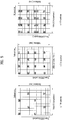
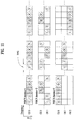
- FIG. 5 shows a pattern of a common reference signal (CRS) in case that 1-TTI (i.e., 1 subframe) has 14 OFDM symbols.
- FIG. 5 (a), FIG. 5 (b) and FIG. 5 (c) relates to a CRS pattern for a system having 1 Tx (transmitting) antenna, a CRS pattern for a system having 2 Tx antennas and a CRS pattern for a system having 4 Tx antennas, respectively.
- R0 indicates a reference signal for an antenna port index 0.
- R1 indicates a reference signal for an antenna port index 1
- R2 indicates a reference signal for an antenna port index 2
- R3 indicates a reference signal for an antenna port index 3.
- FIG. 6 shows that a reference signal pattern is shifted in each cell to prevent reference signals of various cells from colliding with each other.
- a reference signal pattern for one antenna port shown in FIG. 5 (a) is used by a cell #1 (Cell 1) shown in FIG. 6 , in order to prevent collision of reference signals between cells including a cell #2 adjacent to the cell #1, a cell #3 adjacent to the cell #1 and the like, it is able to protect a reference signal in a manner of shifting a reference signal pattern by subcarrier or OFDM symbol unit in frequency or time domain.
- a reference signal is situated in 6-subcarrier interval on a single OFDM symbol, if a shift by subcarrier unit in frequency domain is applied to each cell, at least 5 adjacent cells may be able to situate reference signals on different resource elements, respectively.
- a frequency shift of a reference signal may be represented as the cell #2 and the cell #6 in FIG. 6 .
- PN pseudo-random
- This PN sequence may be applicable by OFDM symbol unit in a single subframe.
- a different sequence may be applicable per cell ID, subframe number or OFDM symbol position.
- DMRS based data demodulation is taken into consideration to support efficient management & operation and developed transmission scheme of reference signals.
- it may be able to define DMRS for at least two layers.
- CSI-RS channel state information
- first three OFDM symbols of each subframe are available.
- 1 to 3 OFDM symbols are available in accordance with overhead of the downlink control channel.
- PCFICH In order to adjust the number of OFDM symbols for a downlink control channel in each subframe, it may be able to use PCFICH. And, it is able to use PHICH to provide an acknowledgment response [ACK/NACK (acknowledgement/negative-acknowledgement)] to an uplink transmission in downlink.
- ACK/NACK acknowledgment/negative-acknowledgement
- PDCCH to transmit control information for a downlink or uplink data transmission.
- FIG. 7 and FIG. 8 show that the above-configured downlink control channels are assigned by resource element group (REG) unit in a control region of each subframe.
- FIG. 7 relates to a system having 1- or 2-Tx antenna configuration and
- FIG. 8 relates to a system having 4-Tx antenna configuration.
- REG corresponding to a basic resource unit for assigning a control channel is configured with 4 contiguous Res in frequency domain except a resource element for assigning a reference signal.
- a specific number of REGs are available for a transmission of a downlink control channel in accordance with overhead of the downlink control channel.
- PCFICH Physical control format indicator channel
- the number of OPFDM symbols used for a control channel is changeable for each subframe.
- information on the OFDM symbol number may be provided via PCFICH.
- the PCFICH should be transmitted in every subframe.
- Table 1 shows CFI (control format indicator) of PCFICH.
- PCFICH Physical Downlink Control Channel
- FIG. 9 is a diagram for a scheme of transmitting PCIFCH.
- REG shown in FIG. 9 is configured with 4 subcarriers, and more particularly, with data subcarriers except RS (reference signal).
- RS reference signal
- a position of the REG may be frequency-shifted per cell (i.e., in accordance with a cell identifier) not to cause interference between cells.
- PCFICH is always transmitted on a 1st OFDM symbol (i.e., OFDM symbol index 0) of a subframe.
- the receiving end acquires the number of OFDM symbols for carrying PDCCH by checking information of PCFICH and is then able to receive control information transmitted on the PDCCH.
- FIG. 10 is a diagram to illustrate positions of PCFICH and PHICH generally applied for a specific bandwidth.
- ACK/NACK information on an uplink data transmission is transmitted on PHICH.
- PHICH groups are created in a single subframe and several PHICHs exist in a single PHICH group. Hence, PHICH channels for several user equipments are included in the single PHICH group.
- PHICH assignment for each user equipment in several PHICH groups are performed using a lowest PRB (physical resource block) index of PUSCH resource allocation and a cyclic shift index for a demodulation reference signal (DMRS) transmitted on a UL (uplink) grant PDCCH.
- the DMRS is a UL reference signal and is the signal provided together with a UL transmission for channel estimation for demodulation of UL data.
- PHICH resource is known through such an index pair as n PHICH group n PHICH seq .
- n PHICH group means a PHICH group number
- n PHICH seq means an orthogonal sequence index in the corresponding PHICH group.
- n PHICH group and n PHICH seq is defined as Formula 1.
- n PHICH group I PRB _ RA lowest _ index + n DMRS mod N PHICH group
- n PHICH seq ⁇ I PRB _ RA lowest _ index / N PHICH group ⁇ + n DMRS mod 2 N SF PHICH
- n DMRS indicates a cyclic shift of DMRS used for a PHICH associated UL transmission.
- N SF PHICH indicates a spreading factor size used for PHICH.
- I PRB _ RA lowest _ index indicates a lowest PRB index of a UL resource allocation.
- n PHICH group indicates the number of the configured PHICH groups and may be defined as Formula 2.
- N PHICH group ⁇ ⁇ N g N RB DL / 8 ⁇ for normal cyclic prefix 2 ⁇ ⁇ N g N RB DL / 8 ⁇ for extended cyclic prefix
- N g indicates an amount of PHICH resource transmitted on PBCH (Physical Broadcast Channel) and N g is represented as N g ⁇ ⁇ 1/6, 1/2, 1, 2 ⁇ in 2-bit size.
- FIG. 11 is a diagram to illustrate a position of a downlink (DL) resource element having PHICH group mapped thereto.
- PHICH group may be configured in different time region (i.e., a different OS (OFDM symbol)) within a single subframe.
- PDCCH Physical downlink control channel
- Control information transmitted on PDCCH may have control information size and usage differing in accordance with a DCI (downlink control information) format. And, a size of the PDCCH may vary in accordance with a coding rate.
- DCI formats used by the legacy 3GPP LTE Release-8/9 may be defined as Table 3.
- the DCI format shown in Table 3 is independently applied per user equipment and PDCCHs of several user equipments can be simultaneously multiplexed within a single subframe.
- the multiplexed PDCCH of each of the user equipments is independently channel-coded and CRC is applied thereto.
- the CRC of the PDCCH is masked with a unique identifier of each of the user equipments and can be applied to enable the corresponding user equipment to receive the PDCCH of its own.
- the user equipment checks whether each of the entire PDCCH channels of the corresponding DCI format matches the PDCCH channel having the ID of the corresponding user equipment for each subframe and needs to perform blind detection until receiving the corresponding PDCCH.
- a basic resource allocation unit of the PDCCH is CCE (control channel element) and a single CCE is configured with 9 TEGs.
- a single PDCCH may be configured with 1, 2, 4 or 8 CCEs.
- PDCCH configured in accordance with each user equipment is interleaved into a control channel region of each subframe and then mapped by a CCE-to-RE mapping rule. This may vary an RE position having a CCE mapped thereto in accordance with the OFDM symbol number for a control channel of each subframe, the PHICH group number, Tx antennas, a frequency shift and the like.
- Uplink (UL) retransmission may be indicated via the aforementioned PHICH and the DCI format 0 (i.e., DCI format for scheduling PUSCH transmission).
- a user equipment receives ACK/NACK for a previous UL transmission via PHICH and is then able to perform a synchronous non-adaptive retransmission.
- a user equipment receives a UL grant via DCI format 0 PDCCH from a base station and is then able to perform a synchronous adaptive retransmission.
- the synchronous transmission means that a retransmission is performed at a predetermined timing point (e.g., (n + k)th subframe) after a timing point (e.g., nth subframe) of transmitting a data packet.
- a retransmission is performed at a predetermined timing point (e.g., (n + k)th subframe) after a timing point (e.g., nth subframe) of transmitting a data packet.
- a retransmission is performed at a predetermined timing point (e.g., (n + k)th subframe) after a timing point (e.g., nth subframe) of transmitting a data packet.
- a frequency resource and transmitting method for performing a retransmission may be set different from those of a previous transmission in accordance with a scheduling control information indicated by a UL grant.
- a user equipment may be able to perform a UL transmission in accordance with control information of the UL grant PDCCH by ignoring the PHICH. Since a new data indicator (NDI) is included in the UL grant PDCCH (e.g., DCI format 0), if NDI bit is toggled more than a previously provided NDI value, the user equipment regards a previous transmission as successful and is then able to transmit new data.
- NDI new data indicator
- the user equipment receives ACK for a previous transmission via PHICH, unless the NDI value is toggled in the UL grant PDCCH received simultaneously with or after the PHICH reception, the user equipment is configured not to flush a buffer for the previous transmission.
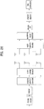
- FIG. 12 is a diagram for a structure of a transmitter by SC-FDMA.
- a single block configured with N symbols inputted to a transmitter is converted to a parallel signal via a serial-to-parallel converter 1201.
- the parallel signal spreads via an N-point DFT module 1202.
- the spreading signal is mapped to a frequency region via a subcarrier mapping module 1203. Signals on subcarriers configure linear combination of N symbols.
- the signal mapped to the frequency region is transformed into a time-domain signal via an M-point IFFT module 1204.
- the time-domain signal is converted to a parallel signal via a parallel-to-serial converter 1205 and then has a CP added thereto.
- the SC-FDMA may be named DFT-s-OFDMA (DFT-spread-OFDMA).
- the signal inputted to the DFT module 1202 has a low PAPR (peak-to-average power ratio) or CM (cubic metric)
- PAPR peak-to-average power ratio
- CM cubic metric
- the signal outputted by the IFFT processing of the IFFT module 1204 may have a low PAPR again.
- transmission is performed by avoiding a non-linear distortion interval of a power amplifier (PA), whereby a cost for implementation of a transmitting end can be reduced.
- PA power amplifier
- FIG. 13 is a diagram to describe a scheme of mapping a signal outputted from the DFT module 1202 to a frequency region.
- a signal outputted from an SC-FDMA transmitter can meet the single carrier property.
- FIG. 13 (a) shows a localized mapping scheme of locally mapping signals outputted from the DFT module 1202 to a specific part of a subcarrier region.
- FIG. 13 (b) shows a distributed mapping scheme of mapping signals outputted from the DFT module 1202 to a whole subcarrier region by being distributed.
- the localized mapping scheme is used.
- FIG. 14 is a block diagram to describe a transmission processing of a reference signal to demodulate a transmitted signal by SC-FDMA.
- a data part is transmitted in a manner of transforming a signal generated from a time domain into a frequency-domain signal by DFT processing, performing subcarrier mapping on the frequency-domain signal, and then performing IFFT processing on the mapped signal [cf. FIG. 12 ].
- a reference signal is defined as directly generated in frequency domain without DFT processing, mapped to subcarrier, undergoing IFFT processing, and then having CP addition thereto.
- FIG. 15 is a diagram to illustrate a symbol position having a reference signal (RS) mapped thereto in a subframe structure according to SC-FDMA.
- FIG. 15 (a) shows that RS is located at 4th SC-FDMA symbol of each of 2 slots in a single subframe in case of a normal CP.
- FIG. 15 (b) shows that RS is located at 3rd SC-FDMA symbol of each of 2 slots in a single subframe in case of an extended CP.
- Clustered DFT-s-OFDMA scheme is described with reference to FIGs. 16 to 19 as follows.
- the clustered DFT-s-OFDMA is the modification of the aforementioned SC-FDMA.
- a DFT-processed signal is segmented into a plurality of sub-blocks and then mapped to a spaced position in frequency domain.
- FIG. 16 is a diagram to describe a clustered DFT-s-OFDMA scheme on a single carrier.
- a DFT output may be partitioned into Nsb sub-blocks (sub-blocks #0 to #Nsb-1).
- the sub-blocks #0 to #NSb-1 are mapped to a single carrier (e.g., carrier of 20MHz bandwidth, etc.) and each of the sub-blocks may be mapped to a position spaced in the frequency region.
- each of the sub-blocks may be locally mapped to the frequency region.
- FIG. 17 and FIG. 18 are diagrams to describe a clustered DFT-s-OFDMA scheme on multiple carriers.
- FIG. 17 is a diagram for one example that a signal can be generated through a single IFFT module. For instance, a DFT output may be segmented into Nsb sub-blocks (sub-blocks #0 to #NSb-1).
- the sub-blocks #0 to #NSb-1 can be mapped to component carriers #0 to #NSb-1, respectively [e.g., each carrier (or cell) may have a bandwidth of 20 MHz], moreover, each of the sub-blocks may be mapped to a frequency region by being localized. And, the sub-blocks mapped to the carriers (or cells) may be transformed into a time-domain signal through a single IFFT module.
- FIG. 18 is a diagram for one example that a signal is generated using a plurality of IFFT modules.
- a DFT output may be segmented into Nsb sub-blocks (sub-blocks #0 to #NSb-1).
- the sub-blocks #0 to #NSb-1 can be mapped to carriers #0 to #NSb-1, respectively [e.g., each carrier (or cell) may have a bandwidth of 20 MHz].
- each of the sub-blocks may be mapped to a frequency region by being localized.
- the sub-blocks mapped to the carriers (or cells) may be transformed into a time-domain signal through the IFFT modules, respectively.
- the DFT-s-OFDMA on the single carrier mentioned with reference to FIG. 16 is called intra-carrier (or intra-cell) DFT-s-OFDMA
- the DFT-s-OFDMA on the multiple carriers (or cells) mentioned with reference to FIG. 17 or FIG. 18 may be called inter-carrier (or inter-cell) DFT-s-OFDMA.
- the intra-carrier DFT-s-OFDMA and the inter-carrier DFT-s-OFDMA may be interchangeably usable.
- FIG. 19 is a diagram to describe a chuck-specific DFT-s-OFDMA scheme of performing DFT processing, frequency domain mapping and IFFT processing by chunk unit.
- the chunk-specific DFT-s-OFDMA may be called Nx SC-FDMA.
- a code block segmented signal is chunk-segmented into parts and channel coding and modulation is performed on each of the parts.
- the modulated signal undergoes the DFT processing, the frequency domain mapping and the IFFT processing in the same manner described with reference to FIG. 12 , outputs from the respective IFFTs are added up, and CP may be added thereto.
- the Nx SC-FDMA scheme mentioned with reference to FIG. 19 may be applicable to a contiguous multi-carrier (or multi-cell) case and a non-contiguous multi-carrier (or multi-cell) case both.
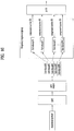
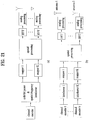
- FIG. 20 is a diagram to illustrate a basic structure of MIMO system having multiple Tx antennas and/or multiple Rx (receiving) antennas. Each block shown in FIG. 20 conceptionally indicates a function or operation in a transmitting/receiving end for MIMO transmission.
- a channel encoder shown in FIG. 20 indicates an operation of attaching a redundancy bit to an input data bit, whereby effect of noise and the like from a channel can be reduced.
- a mapper indicates an operation of converting data bit information to data symbol information.
- a serial-to-parallel converter indicates an operation of converting serial data to parallel data.
- a multi-antenna encoder indicates an operation of transforming a data symbol into a time-spatial signal. A multi-antenna of a transmitting end plays a role in transmitting this time-spatial signal on a channel, while a multi-antenna of a receiving end plays a role in receiving the signal on the channel.
- a multi-antenna decoder shown in FIG. 20 indicates an operation of transforming the received time-spatial signal into each data symbol.
- a parallel-to-serial converter indicates an operation of converting a parallel signal to a serial signal.
- a demapper indicates an operation of transforming a data symbol to a bit information.
- a decoding operation for a channel code is performed by a channel decoder, whereby data can be estimated.
- the MIMO transceiving system mentioned in the above description may have a single or several codewords spatially in accordance with a space multiplexing ratio.
- a case of having a single codeword spatially is called a single codeword (SCW) structure.
- SCW single codeword
- MCW multiple codeword
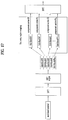
- FIG. 21 (a) is a block diagram to represent functionality of a transmitting end of an MIMO system having the SCW structure.
- FIG. 21 (b) is a block diagram to represent functionality of a transmitting end of an MIMO system having the MCW structure.
- a codebook based precoding scheme means the scheme performed in a following manner. First of all, a set of precoding matrixes is determined in a transmitting end and a receiving end. Secondly, the transmitting end measures channel information from the transmitting end and then feeds back information (i.e., a precoding matrix index (PMI)) indicating what is a most appropriate precoding matrix to the transmitting end. Finally, the transmitting end applies an appropriate precoding to a signal transmission based on the PMI. Since the appropriate precoding matrix is selected from the previously determined precoding matrix set, although an optimal precoding is not always applied, this is more advantageous than the explicit feedback of optimal precoding information actually carried on channel information in reducing feedback overhead.
- PMI precoding matrix index
- FIG. 22 is a diagram to describe basic concept of codebook based precoding.
- a transmitting and a receiving end share codebook information including a prescribed number of precoding matrixes in accordance with a transmission rank, the number of antennas and the like.
- codebook information including a prescribed number of precoding matrixes in accordance with a transmission rank, the number of antennas and the like.
- feedback information is finite, it is able to use the precoding based codebook scheme.
- the receiving end measures a channel status via a received signal and is then able to deed back information (i.e., indexes of the corresponding precoding matrixes) on the finite number of preferred precoding matrixes based on the above-mentioned codebook information to the transmitting end.
- the receiving end is able to select an optimal precoding matrix in a manner of measuring a received signal by ML (maximum likelihood) or MMSE (minimum mean square error) scheme.
- FIG. 22 shows that the receiving end transmits the precoding matrix information per codeword to the transmitting end, by which the present invention may be non-limited.
- the transmitting end may be able to select a specific precoding matrix from the codebook based on the received information. Having selected the precoding matrix, the transmitting end performs a precoding in a manner of multiplying layer signals, of which number corresponds to the transmission rank, by the selected precoding matrix and may be then able to transmit a precoded transmission signal via a plurality of antennas.
- the precoding matrix the number of rows is equal to that of the antennas and the number of columns is equal to a rank value. Since the rank value is equal to the number of the layers, the number of the columns is equal to the number of layers. For instance, if the number of the Tx antennas and the number of the transmission layers are 4 and 2, respectively, the precoding matrix can be configured with 4 ⁇ 2 matrix. Information transmitted via each layer can be mapped to each antenna via the precoding matrix.
- the receiving end Having received the signal precoded and transmitted by the transmitting end, the receiving end is able to reconstruct the received signal by performing a processing inverse to that of the precoding performed by the transmitting end.
- the inverse processing of the precoding may be performed in a manner of multiplying the received signal by Hermit matrix (PH) of the precoding matrix (P) used for the precoding of the transmitting end.
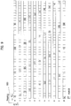
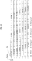
- Table 4 in the following indicates a codebook used for a downlink transmission using 2 Tx antennas in 3GPP LTE Release-8/9 and Table 5 indicates a codebook used for a downlink transmission using 4 Tx antennas in 3GPP LTE Release-8/9.
- I indicates 4 ⁇ 4 unitary matrix and u n indicates a value given by Table 5.
- the above-mentioned codebooks have such a common property as a constant modulus (CM) property, a nested property, a constrained alphabet property and the like.
- CM constant modulus
- a nested property a precoding matrix of a low rank is designed to be configured with a subset of a specific column of a precoding matrix of a high rank.
- constrained alphabet property each element of every precoding matrix within a codebook is constrained.
- each element of a precoding matrix is limited only to an element ( ⁇ 1) used for BPSH (binary phase shift keying), elements ( ⁇ 1, ⁇ j ) used for QPSK (quadrature phase shit keying), or elements ⁇ 1 , ⁇ j , ⁇ 1 + j 2 , ⁇ ⁇ 1 + j 2 used for 8-PSK.
- ⁇ 1 used for BPSH (binary phase shift keying)
- elements ( ⁇ 1, ⁇ j ) used for QPSK quadrature phase shit keying
- elements ⁇ 1 , ⁇ j , ⁇ 1 + j 2 used for 8-PSK.
- alphabet of each element of every precoding matrix within the codebook is configured with ⁇ 1 , ⁇ j , ⁇ 1 + j 2 , ⁇ ⁇ 1 + j 2 , it may be represented as having the constrained alphabet property.
- channel information fed back by a user equipment is used for a DL transmission.
- it is able to feed back DL channel information via PUCCH or PUSCH.
- PUCCH channel information is periodically fed back.
- PUSCH channel information is aperiodically fed back in accordance with a request made by a base station.
- feedback of channel information may be performed in a manner of feeding back the channel information on a whole frequency band (i.e., wideband (WB)) or the channel information on a specific number of RBs (i.e., subband (SB)).
- WB wideband
- SB subband
- FIG. 23 shows examples of configuration of 8 Tx (transmitting) antennas.
- FIG. 23 (a) shows a case that N antennas configure independent channels without being grouped, which is generally called ULA (uniform linear array).
- ULA uniform linear array
- the ULA configuration may be available.
- multiple antennas are arranged in a manner being spaced apart from each other. Hence, it may be insufficient for a space of a transmitter and/or receiver to configure independent channels.
- FIG. 23 (b) shows an antenna configuration (i.e., paired ULA) of ULA type in which 2 antennas form a pair.
- an associated channel is established between a pair of the antennas and may be independent from that of antennas of another pair.
- the 3GPP LTE Release-10 system is able to use 8 Tx antennas in DL.
- the ULA antenna configuration shown FIG. 23 (a) or FIG. 23 (b) may become inappropriate. Therefore, it may be able to consider applying a dual-polarized (or cross-polarized) antenna configuration shown in FIG. 23 (c) .
- this configuration of Tx antennas even if a distance 'd' between antennas is relatively short, it is able to configure independent channels by lowering correlation. Therefore, data transmission of high throughput can be achieved.
- a transmitting end and a receiving end share a pre-defined codebook with each other, it is able to lower an overhead for the receiving end to feed back precoding information to be used for MIMO transmission from the transmitting end. Hence, it is able to apply efficient precoding.
- a precoder matrix For one example of configuring a pre-defined codebook, it is able to configure a precoder matrix using DFT (discrete Fourier transform) matrix or Walsh matrix. Alternatively, it is able to configure precoders of various types by combination with a phase shift matrix, a shift diversity matrix or the like.
- DFT discrete Fourier transform
- n ⁇ n DFT matrix can be defined as Formula 3.
- the DFT matrix shown in Formula 4 is configured, it is able to create G rotated DFTn matrixes. And, the created matrixes may meet the property of the DFT matrix.
- the householder-based codebook structure may mean the codebook configured with householder matrix.
- the householder matrix is the matrix used for householder transform.
- the householder transform is a sort of linear transformation and may be usable in performing QR decomposition.
- the QR decomposition may mean that a prescribed matrix is decomposed into an orthogonal matrix (Q) and an upper triangular matrix (R).
- the upper triangular matrix means a square matrix of which components below main diagonal components are all zeros.
- One example of the 4 ⁇ 4 householder matrix is shown in Formula 5.
- n ⁇ n precoding matrix is created using the householder transformation and a column subset of the created precoding matrix can be configured to be used as a precoding matrix for a transmission of a rank smaller than n.
- a precoding operation used for a multi-antenna transmission may be explained as an operation of mapping a signal transmitted via layer(s) to antenna(s).
- Y transmission layers or streams
- X Tx antennas X Tx antennas
- a transmitting end receives a feedback of at least one precoding matrix index (PMI) from a receiving end and is then able to configure a precoder matrix.
- PMI precoding matrix index
- Formula 6 shows one example of a codebook configured with nc matrixes.
- P N t ⁇ R k ⁇ P 1 N t ⁇ R , P 2 N t ⁇ R , P 3 N t ⁇ R , ... , P n c N t ⁇ R
- k indicates a specific resource index (e.g., a subcarrier index, a virtual resource index, a subband index, etc.).
- Formula 6 may be configured in form of Formula 7.
- P M t ⁇ R ,2 may be configured in form of shifting P M t ⁇ R ,1 by a specific complex weight w 2 .
- w 2 a specific complex weight
- Formula 8 may be represented as Formula 9 using Kroneker product ( ⁇ ).
- Kroneker product is an operation for 2 matrixes in random size. As a result of Kroneker product operation, it is able to obtain a block matrix.
- Kroneker product of an m ⁇ n matrix A and a p ⁇ q matrix B (i.e., A ⁇ B) may be represented as Formula 10.
- amn indicates an element of the matrix A
- bpq indicates an element of the matrix B.
- a ⁇ B a 11 b 11 a 11 b 12 ⁇ a 11 b 1 ⁇ q ⁇ ⁇ a 1 ⁇ n b 11 a 1 ⁇ n b 12 ⁇ a 1 ⁇ n b 1 ⁇ q a 11 b 21 a 11 b 22 ⁇ a 11 b 2 ⁇ q ⁇ ⁇ a 1 ⁇ n b 21 a 1 ⁇ n b 22 ⁇ a 1 ⁇ n b 2 ⁇ q ⁇ ⁇ ⁇ ⁇ ⁇ ⁇ ⁇ a 11 b p 1 a 11 b p 2 ⁇ a 11 b pq ⁇ ⁇ a 1 ⁇ n b p 1 a 1 ⁇ n b p 2 ⁇ a 1 ⁇ n b pq ⁇ ⁇ ⁇ a 1 ⁇ n b p 1 a 1 ⁇ n b p 2 ⁇ a 1 ⁇ n
- a partial matrix w 1 w 2 of precoding and P M t ⁇ R ,1 in Formula 9 may be independently fed back from a receiving end. And, a transmitting end is able to configure and use a precoder like Formula 8 or Formula 9 using each feedback information.
- W is always configured in form of 2 ⁇ 1 vector and may be configured in form of a codebook shown I Formula 11.
- W ⁇ 1 e j 2 ⁇ ⁇ N i , i 0 , ... , N ⁇ 1
- N indicates the total number of precoding vectors contained in the codebook and i may be used as an index of a vector.
- i may be usable by being set to 2, 4 or 8.
- P M t ⁇ R ,1 may be configured as a codebook for 4 Tx antennas or a codebook for 2 Tx antennas.
- the codebook of Table 4 or Table 5 e.g., the codebook for 2 or 4 Tx antennas defined in 3GPP LTE Release-8/9 is usable.
- P M t ⁇ R ,1 may be configured in rotated DFT form as well.
- a matrix W may be available in form of 2 ⁇ 2 matrix.
- Formula 12 shows one example of the 2 ⁇ 2 matrix W .
- the precoder configuring method according to Formula 9 or Formula 12 may apply differently in accordance with each rank.
- the method of Formula 9 is used for a case of a rank equal to or lower than 4 ( R ⁇ 4).
- the method of Formula 12 may be used for a case of a rank equal to or higher than 5 ( R ⁇ 5).
- the W and P mentioned in association with Formula 9 and Formula 12 may be fed back to have the property as shown in Table 6.
- Case W/P Frequency granularity 1 One of two matrixes may be configured to be fed back on subband and the other may be configured to be fed back on wideband.
- Frequency granularity 2 One of two matrixes may be configured to be fed back on nest-M band and the other may be configured to be fed back on wideband.
- Time granularity One of two matrixes may be configured to be fed back by periods N and the other may be configured to be fed back by periods M.
- Feedback channel 1 One of two matrixes may be configured to be fed back on PUSCH and the other may be configured to be fed back on PUCCH.
- one (e.g., W) of two matrixes may be configured to be fed back on subband and the other (e.g., P) may be configured to be fed back on wideband.
- both Q and P may be configured to be fed back on wideband.
- Unequal protection One (e.g., P) of two matrixes may be configured to be coded at a more reliable rating rate and the other (e.g., W) may be configured to be coded at a relatively low coding rate.
- Alphabet restriction 1 Alphabet of a matrix W may be configured to be constrained by BPSK and alphabet of a matrix P may be configured to be constrained by QPSK or 8 PSK.
- Alphabet restriction 2 Alphabet of a matrix W may be configured to be constrained by QPSK and alphabet of a matrix P may be configured to be constrained by QPSK or 8 PSK.
- P M t ⁇ M may be configured with a rotated DFT matrix or a codebook of another type.
- a method of applying a precoder in accordance with a specific resource may be represented as Formula 15.
- P N t ⁇ R , n , m k W k mod n c ⁇ P k mod m c
- k indicates a specific resource region.
- a precoding matrix for a specific resource region k is determined by such a modulo operation as Formula 15.
- n c and m c may indicate a size or subset of a codebook for matrix W and a size or subset of a codebook for a matrix P, respectively.
- the matrix W may be configured to perform a modulo operation in accordance with a physical resource block (PRB) index and the matrix P may be configured to perform a modulo operation in accordance with a subframe index.
- the matrix W may be configured to perform a modulo operation in accordance with a subframe index and the matrix P may be configured to perform a modulo operation in accordance with a physical resource block (PRB) index.
- PRB physical resource block
- the matrix W may be configured to perform a modulo operation in accordance with a physical resource block (PRB) index and the matrix P may be configured to perform a modulo operation in accordance with a subband index.
- the matrix W may be configured to perform a modulo operation in accordance with a subband index and the matrix P may be configured to perform a modulo operation in accordance with a physical resource block (PRB) index.
- PRB physical resource block
- a precoder cycling using a modulo operation is applied to one of the two matrixes only and the other may be fixed to use.
- the feedback scheme used by the legacy 3GPP LTE Release-8/9 may be applied in a manner of being extended. For instance, it is able to feed back such channel state information (CSI) as RI (Rank Indicator), PMI (Precoding Matrix Index), CQI (Channel Quality Information) and the like.
- CSI channel state information
- RI Rank Indicator
- PMI Precoding Matrix Index
- CQI Channel Quality Information
- a receiving end may be able to transmit a precoding matrix index (PMI) to the transmitting end.
- PMI precoding matrix index
- a precoding matrix may be indicated by combination of 2 different PMIs.
- the receiving end feeds back 2 different PMIs (i.e., 1st PMI and 2nd PMI) to the transmitting end.
- the transmitting end determines the precoding matrix indicated by the combination of the 1st and 2nd PMIs and is then able to apply the determined precoding matrix to the MIMO transmission.
- this feedback codebook supports SU-MIMO only in case of a rank higher than 2, is optimized for both SU-MIMO and MU-MIMO in case of a rank equal to or lower than 2, and is compatible with various antenna configurations.
- the codebook for MU-MIMO needs to be designed to correctly operate on a channel having high correlation. Since DFT vectors provide good performance on a channel having high correlation, it may be able to consider having DFT vector contained in a codebook set of a rank up to a rank-2. In high scattering propagation environment (e.g., an indoor environment having many reflective waves, etc.) capable of producing many space channels, SU-MIMO operation may be preferred as the MIMO transmission scheme. Hence, it may be able to consider designing a codebook for a rank higher than the rank-2 to have god performance in separating multiple layers.
- high scattering propagation environment e.g., an indoor environment having many reflective waves, etc.
- one precoder structure has good performance for various antenna configurations (e.g., low-correlation, high-correlation, cross-pole, etc.).
- a cross-polarized array having an antenna interval of 4 ⁇ may be formed in a low-correlation antenna configuration
- a ULA having an antenna interval of 0.5 ⁇ may be formed in a high-correlation antenna configuration
- a cross-polarized array having an antenna interval of 0.5 ⁇ may be formed in a cross-polarized antenna configuration.
- the DFT based codebook structure may be able to provide good performance for the high-correlation antenna configuration.
- block diagonal matrixes may be more suitable for the cross-polarized antenna configuration.
- a diagonal matrix is introduced into a codebook for 8 Tx antennas, it is able to configure a codebook that provides god performance for all antenna configurations.
- the codebook design reference is to meet the unitary codebook, the CM property, the constrained alphabet, the proper codebook size, the nested property and the like. This applies to the 3GPP LTE Release-8/9 codebook design. And, it may be able to consider applying such a codebook design reference to the 3GPP LTE Release-10 codebook design supportive of the extended antenna configuration.
- a codebook in large size e.g., a codebook in size over 4 bits for Rank 1 or Rank 2
- a codebook in 4-bit size may be sufficient.
- a 1st base matrix may be represented as a diagonal matrix shown in Formula 17 for a co-polarized antenna group.
- W ⁇ 1 W 1 0 0 W 1 W 1 : 4 ⁇ N
- the 2nd base matrix may be represented using an identity matrix.
- the 2nd base matrix may be represented as Formula 18.
- Formula 18 a relation between a coefficient '1' of a 1st row of the 2nd base matrix and a coefficient 'a' or '-a' of a 2nd row thereof may be able to reflect the adjustment of a relative phase between orthogonal polarizations.
- W ⁇ 2 I I aI ⁇ aI I : N ⁇ N
- the codebook expressed using the inner product like Formula 19 can be simplified into Formula 20 using Kroneker product.
- W W 2 ⁇ W 1 W 1 : 4 ⁇ N , W 2 : 2 ⁇ M
- a precoding matrix included in a codebook W includes 4 ⁇ 2 rows and N ⁇ M columns.
- it can be used as a codebook for 8 Tx antennas and transmission of Rank 'N ⁇ M'.
- N for W1 becomes R/M.
- a precoding matrix W for configuring a codebook may be defined in form of W1 ⁇ W2.
- W1 may be able to have such a form of a block diagonal matrix as X 0 0 X .
- X corresponding to a block of a block diagonal matrix W1 may be configured with a matrix in size of 4 ⁇ Nb.
- 16 4Tx DFT beams can be defined for the X.
- beams indexes may be given as 0, 1, 2, ..., and 15, respectively.
- the adjacent overlapping beams may be usable to reduce an edge effect in frequency-selective precoding.
- Nb 4
- 8 W1 matrixes can be defined.
- one W1 may include beams overlapping with the adjacent W1.
- beam indexes are given as 0, 1, 2, ..., and 15, respectively, for example, it is able to configure 8 W1 matrixes, of which beams overlapping with the adjacent W1 matrix, such as ⁇ 0, 1, 2, 3 ⁇ , ⁇ 2, 3, 4, 5 ⁇ , ⁇ 4, 5, 6, 7 ⁇ , ⁇ 6, 7, 8, 9 ⁇ , ⁇ 8, 9, 10, 11 ⁇ , ⁇ 10, 11, 12, 13 ⁇ , ⁇ 12, 13, 14, 15 ⁇ , and ⁇ 14, 15, 0, 1 ⁇ .
- a W1 codebook for Rank 1 or Rank 2 may be defined as Formula 21.
- CB1 W 1 0 , W 1 1 , W 1 2 , ⁇ , W 1 7
- the W2 codebook (CB2) for Rank 1 can be configured as Formula 22.
- W 2 ⁇ CB 2 1 2 Y Y , 1 2 Y jY , 1 2 Y ⁇ Y , 1 2 Y ⁇ jY Y ⁇ 1 0 0 0 0 1 0 0 0 0 0 1 0 0 0 0 0 1 0 0 0 0 0 1
- the W2 codebook (CB2) for Rank 2 can be configured as Formula 23.
- W 2 ⁇ CB 2 1 2 Y Y Y ⁇ Y , 1 2 Y Y j ⁇ Y ⁇ j ⁇ Y Y ⁇ 1 0 0 0 0 1 0 0 0 0 0 1 0 0 0 0 0 1 0 0 0 0 0 1 0 0 0 0 0 1 0 0 0 0 0 1 0 0 0 0 0 1
- 4 W1 matrixes can be defined.
- one W1 may include beams overlapping with the adjacent W1.
- beam indexes are given as 0, 1, 2, ..., and 15, respectively, for example, it is able to configure 4 W1 matrixes, of which beams overlapping with the adjacent W1 matrix, such as ⁇ 0,1,2,...,7 ⁇ , ⁇ 4,5,6,...,11 ⁇ , ⁇ 8,9,10,...,15 ⁇ , and ⁇ 12,...,15,0,...,3 ⁇ .
- a W1 codebook for Rank 3 or Rank 4 may be defined as Formula 24.
- X(n) corresponding to a block of a block diagonal matrix W1(n) is defined and a W1 codebook (CB1) can be
- the selection of 8 kinds of different matrixes is possible for Rank 3 and 2 kinds of different QPSK co-phases are applicable for Rank 3.
- total 16 W2 matrixes can be defined.
- the W2 codebook (CB2) for Rank 3 can be configured as Formula 25.
- W 2 ⁇ CB 2 1 2 Y 1 Y 2 Y 1 ⁇ Y 2 , 1 2 Y 1 Y 2 j Y 1 ⁇ j Y 2 Y 1 Y 2 ⁇ e 1 e 1 e 5 e 2 e 2 e 6 e 3 e 3 e 7 e 4 e 4 e 8 e 5 e 1 e 5 e 6 e 2 e 6 e 7 e 3 e 7 e 8 e 4 e 8
- en indicates 8 ⁇ 1 vector, nth element has a value of 1, and the rest of elements mean a selection vector having a value of 0.
- the W2 codebook (CB2) for Rank 4 can be configured as Formula 26.
- W 2 ⁇ CB 2 1 2 Y Y Y ⁇ Y , 1 2 Y Y j ⁇ Y ⁇ j ⁇ Y Y ⁇ e 1 e 5 e 2 e 6 e 3 e 7 e 4 e 8
- X corresponding to a block of a block diagonal matrix W1 can be configured with DFT matrix in size of 4 ⁇ 4 and one W1 matrix can be defined.
- W2 may be defined as a product of a matrix I I I ⁇ I and a row selection matrix in a fixed size of 8 ⁇ r.
- 4 W2 matrixes can be defined for Rank 5, since selection of 4 kinds of different matrixes is possible.
- 4 W2 matrixes can be defined.
- For Rank 7 since selection of 1 kind of a matrix is possible, one W2 matrix can be defined.
- one W2 matrix can be defined.
- the matrix I I I ⁇ I is introduced to enable all polarized groups for each transmission layer to be identically used and good performance may be expected for a transmission of a high rank having a spatial channel having more scattering.
- the I means an identity matrix.
- the W1 codebook or the W2 codebook for Rank 5 to Rank 8 can be defined as Formula 27.
- X 1 2 ⁇ 1 1 1 1 1 j ⁇ 1 ⁇ j 1 ⁇ 1 1 ⁇ 1 1 ⁇ j ⁇ 1 j
- W 1 X 0 0 X
- the W1 codebook for Rank 5 to Rank 8 is configured with one W1 matrix only.
- I4 in the W2 codebook for Rank 5 to Rank 8 means an identity matrix in size of 4 ⁇ 4.
- a matrix Y can be defined as one of Formula 28 to Formula 31 for example.
- the matrix Y for Rank 5 can be defined as Formula 28. Y ⁇ e 1 e 2 e 3 e 4 e 5 , e 2 e 3 e 4 e 5 e 6 , e 3 e 4 e 5 e 6 e 7 , e 4 e 5 e 6 e 7 e 8
- the matrix Y for Rank 6 can be defined as Formula 29. Y ⁇ e 1 e 2 e 3 e 4 e 5 e 6 , e 2 e 3 e 4 e 5 e 6 e 7 , e 3 e 4 e 5 e 6 e 7 e 8 , e 4 e 5 e 6 e 7 e 8 e 1
- the matrix Y for Rank 7 can be defined as Formula 30.
- Y e 1 e 2 e 3 e 4 e 5 e 6 e 7
- the matrix Y for Rank 8 can be defined as Formula 31.
- Y I 8
- the I8 means 8 ⁇ 8 identity matrix.
- the present invention relates to a technique in which a serving cell transmits resource allocation information about a sounding reference signal (SRS) of a UE and location information of the UE to eNBs around which a 2-dimensional active antenna system (2D-AAS) is installed, based on a 3D MIMO system in which the 2D-AAS is installed, for efficient handover of the UE.
- SRS sounding reference signal
- 2D-AAS 2-dimensional active antenna system
- the AAS includes active antennas each including an active circuit and may be more efficiently used to reduce interference or perform beamforming by varying an antenna pattern according to circumstance.
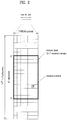
- FIG. 24 is a diagram referred to in explaining a multi-dimensional AAS.
- a 2D-AAS is predicted to establish a plurality of antenna systems by installation of antennas in a vertical direction and a horizontal direction as illustrated in FIG. 24 .
- a main lobe of antennas may adjust a beam direction even in a vertical plane as well as in a horizontal plane in terms of antenna pattern, thereby more efficiently enabling three-dimensional beam adaptation. Then, it is possible to actively vary a transmission beam according to the location of a UE.
- UEs calculate a reference signal received power (RSRP) for handover.
- RSRP reference signal received power
- the RSRP is calculated using a CRS and the CRS is not always used by all antenna ports due to an overhead problem.
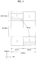
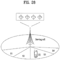
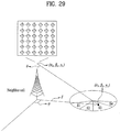
- FIG. 25 is a diagram referred to in explaining CRS transmission when a 2D-AAS is used.
- a UE is located near a serving cell having four antennas and a neighbor cell includes a 2D-AAS eNB having a total of 36 antenna elements in which 6 antenna elements in a vertical direction and 6 antenna elements in a horizontal direction are included.
- the UE shown in FIG. 25 performs handover by comparing an RSRP of the cell thereof and an RSRP of the neighbor cell. If the neighbor cell uses one direction beam, B, as a CRS beam due to the above-described CRS overhead problem, there is a high probability that the UE may not perform handover due to a wrong RSRP although the UE receives a beam C of the neighbor cell.
- B a direction beam
- the CRS beam is carried on one vertical antenna element without applying a weight to antennas of a vertical direction
- a thick beam such as a beam A is formed and the overall power of the beam is weakened. Accordingly, although the UE may receive the beam C of the neighbor cell, the UE determines handover without such consideration.
- the UE may use several CRS beams or CSI-RS beams, overhead may occur due to increased RS transmission.
- the present invention proposes a new handover method for improving inaccurate CRS based handover when eNBs including a 2D-AAS are installed.
- FIG. 26 is a diagram illustrating an embodiment of the present invention. The present invention will now be described with reference to FIG. 26 .
- a serving cell configures an SRS for at least one UE (located therein).
- the serving cell may signal SRS configuration (e.g., information about a resource to which the SRS is allocated) for the UEs to neighbor cells.
- the serving cell may signal location information of the UEs as well.
- the serving cell may transmit the SRS configuration information and the UE location information to the neighbor cells, the serving cell may perform transmission only when the neighbor cells correspond to eNBs equipped with a 2D-AAS in which there is a high probability that an RSRP is inaccurate.
- the serving cell transmits information capable of estimating the location of the UE to some degree and this information may be i) PMI information/weight information about a channel between the UE and the serving cell or ii) PMI information/weight information about an antenna in a vertical direction when the serving cell is equipped with the 2D-AAS.
- the information about the location of the UE may be iii) GPS information of the UE or iv) information about a region in which the UE is expected to be currently located. Such information approximately indicates the location between the serving cell and the UE, making it possible for the neighbor cells to estimate an approximate location of the UE.
- the information may be used during application of a receiving vector for more accurate RSRP when neighbor cells receive the SRS of the UE.
- the neighbor cells receive SRSs of the UEs.
- the neighbor cells may receive the SRSs of the UEs by applying a receiving vector capable of receiving the SRSs of the UEs as efficiently as possible, using the location information of the UEs received in step S2603.
- the neighbor cells receive the SRSs of the UEs using the SRS resource configuration of the UEs received in step S2603.
- the neighbor cells estimate RSRPs of the UEs as accurately as possible by applying the receiving vector according to PMI information or weight information of a vertical/horizontal direction, GPS information, or region information, for the location information of the UEs, transmitted by the serving cell. Therefore, the neighbor cells estimate SRS based RSRPs to which the receiving vector is applied.
- the neighbor cells may apply the receiving vector by estimating a region covered by the serving cell.
- step S2607 the neighbor cells transmit the SRS based RSRPs to which the receiving vector is applied in step 2605 to the serving cell.
- reference signal received quality may be used instead of the RSRP. Since the RSRQ further considers total received signal strength relative to the RSRP, the serving cell has an advantage of recognizing a channel state in more detail.
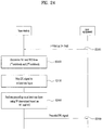
- the serving cell determines a specific UE that is to perform handover among the UEs, based on the SRS based RSRPs to which the receiving vector is applied in step S2607 and directs the determined specific UE to perform handover.
- a serving eNB compares an SRS based RSRP measured by the serving cell and an SRS based RSRP measured by the neighbor cell. If the RSRP measured by the neighbor cell is greater than the RSRP measured by the serving cell by a prescribed level or more, the serving eNB may determine that handover is needed.
- step S2609 While it is assumed in the present invention that handover is performed in step S2609, there may be a difference in channel between UL and DL and an interference environment may also differ in UL and DL. Accordingly, even if handover is determined in step S2609, an additional confirmation procedure may be needed.
- a cell to which a UE is handed over transmits a precoded CSI-RS using a receiving vector vector calculated in step S2605 to the UE that is determined to perform handover.
- the serving eNB may signal CSI-RS configuration (e.g., a configuration index, a transmission period, etc.) of each cell to the UE and request that the UE perform measurement.
- the serving cell may configure a CSI-RS therefor and a CSI-RS for the neighbor cell.
- the neighbor cell and the serving cell may transmit CSI-RSs to which respective precoding is applied to respective CSI-RS resources.
- the UE may determine whether handover is proper based on a received beam and report a determined result to the serving cell or transmit a confirmation message to the serving cell. For example, the UE compares RSRPs for respective CSI-RSs and, if a difference between the RSRPs is equal to or greater than a given level, the UE may confirm handover. If the difference is less than a given level or an absolute specific number (e.g., a level at which it is difficult to perform communication), the UE may deny a corresponding handover command.
- a given level or an absolute specific number e.g., a level at which it is difficult to perform communication
- receiving powers of the UEs may be more accurately measured in step S2605 and SRS based RSRPs are measured in consideration of the measured receiving powers, thereby accurately performing handover relative to legacy handover.
- step S2603 and step S2605 of the present invention a method in which a neighbor cell determines a receiving vector in step S2603 and step S2605 of the present invention will be described in more detail.
- the serving cell may transmit, to the neighbor cells, information about at least one of i) weight/PMI information about a horizontal antenna of the UE, ii) weight/PMI information about a vertical antenna of the UE, iii) GPS information of the UE, iv) GPS information of the UE, v) information indicating absence (null) of location information of the UE.
- the serving cell informs the neighbor cells of the weight/PMI information of the horizontal direction of the UE. For example, it is assumed that the serving cell informs the neighbor cells of the weight/PMI information of the horizontal direction of the UE and this information is always based on rank 1. Since whether weight/PMI information based on rank 1 is stored in each UE is uncertain, the serving cell may additionally request that the UE transmit the weight/PMI information based on rank 1. Although the serving cell may request that all UEs transmit weight/PMI information, the serving cell checks whether prestored weight/PMI information is present and requests that only UEs that do not store weight/PMI information transmit weight/PMI information, thereby reducing signaling overhead.
- FIG. 27 and FIG. 28 are diagrams referred to in explaining the case in which a neighbor cell estimates a beamforming state of a serving cell according to the present invention.
- a UE has a high probability of using a beam S3 between a serving cell and the UE as a weight vector/PMI.
- the serving cell operates with four PMIs forming beams S1, S2, S3, and S4, respectively.
- the serving cell informs a neighbor cell of PMI information about the beam S3.
- the neighbor cell may be aware of whether the beam S3 illuminated by the serving cell forms the best beam for the UE, through the information about the received beam S3.
- the neighbor cell may estimate a region towards which a large quantity of beam is illuminated by the serving cell.
- PMI Information about a region such as S i may differ according to the height of an eNB of the serving cell and the length between antenna elements of the serving cell or the length between antenna ports. Accordingly, it is assumed that information about a region towards which a beam of the serving cell is illuminated is preshared by eNBs.
- ⁇ i , ⁇ i , and ⁇ ⁇ denote x, y, and z coordinates of the weight center of each illuminated region, respectively.
- the serving cell may transmit such information of C S i to the neighbor cell instead of PMI/weight information.
- FIG. 29 illustrates the case in which a neighbor cell adaptively performs beamforming based on region information according to the present invention.
- ⁇ denotes an angle of a vertical direction in the global coordinate system and ⁇ denotes an angle of a horizontal direction in the global coordinate system.
- the angles ⁇ and ⁇ are transformed into angles ⁇ ' and ⁇ ' in a local coordinate system.
- the neighbor cell may calculate a receiving vector vector as indicated by Formula 32.
- w m , n exp ⁇ 2 ⁇ ⁇ j ⁇ n ⁇ 1 ⁇ d v ⁇ ⁇ cos ⁇ ′ + m ⁇ 1 ⁇ d h ⁇ ⁇ sin ⁇ ′ ⁇ sin ⁇ ′
- Formula 32 indicates that a beam in a direction of ⁇ ' and ⁇ ' is received with the highest energy.
- m and n denote antenna element numbers of a horizontal axis and a vertical axis, respectively.
- the serving cell is equipped with a 2D-AAS and informs the neighbor cell of the above-described weight/PMI information of the horizontal direction and vertical direction of the UE (i.e., information of i) and ii)) and this information is always based on rank 1.
- the serving cell may additionally request that a UE transmit the weight/PMI information based on rank 1.
- FIG. 30 is a diagram referred to in explaining the case in which weight/PMI information of a horizontal direction and a vertical direction is transmitted according to the present invention.
- a neighbor cell estimates which region each beam of a serving cell mainly illuminates.
- Information about the region as illustrated in FIG. 30 through PMIs may differ according to the height of an eNB of the serving cell and the length between antenna elements of the serving cell or the length between antenna ports. Accordingly, it is assumed that information about a region towards which a beam of the serving cell is illuminated is preshared by eNBs.
- ⁇ i , ⁇ i , and ⁇ i denote x, y, and z coordinates of the weight center of each illuminated region, respectively.
- the serving cell may transmit such information of C S i to a neighbor cell instead of PMI/weight information.
- the neighbor cell may easily calculate ⁇ and ⁇ in a global coordinate system.
- ⁇ denotes an angle of a vertical direction in the global coordinate system
- ⁇ denotes an angle of a horizontal direction in the global coordinate system.
- the angles ⁇ and ⁇ are transformed into angles ⁇ ' and ⁇ ' in a local coordinate system.
- the neighbor cell may calculate a receiving vector vector as indicated by Formula 32.
- Formula 32 indicates that a beam in a direction of ⁇ ' and ⁇ ' is received with the highest energy.
- the serving cell may inform the neighbor cell of GPS information of a UE.
- the eNB may receive the GPS information of the UE by frequently requesting that the UE transmit the GPS information of the UE.
- the serving cell transmits ( ⁇ i , ⁇ i , ⁇ i ) which is the GPS information of the UE to the neighbor cell.
- the neighbor cell may determine a receiving vector by a weight vector at which a beam best illuminates the location ( ⁇ i , ⁇ i , ⁇ i ) based on the information of ( ⁇ i , ⁇ i , ⁇ i ) and location information of an eNB thereof.
- the neighbor cell is aware of ( ⁇ i , ⁇ i , ⁇ i ) transmitted by the serving cell as in FIG. 29 and it is assumed that the neighbor cell is also aware of ( ⁇ b , ⁇ b , ⁇ b ) which is location information thereof. Then, the neighbor cell may easily calculate ⁇ and ⁇ of FIG. 29 in a global coordinate system. Since ⁇ and ⁇ denote angles in the global coordinate system, the angles ⁇ and ⁇ are transformed into angles ⁇ ' and ⁇ ' in a local coordinate system according to a direction of an antenna of an eNB. Then, the neighbor cell may calculate a receiving vector vector using Formula 32. That is, as described above, a beam in a direction of ⁇ ' and ⁇ ' may be received with the highest energy using Formula 32.
- the serving cell may inform the neighbor cell of region information of a UE.
- the region information of the UE may be defined as information about a region to which the UE belongs when the serving cell is divided into a plurality of regions as illustrated in FIG. 30 .
- ⁇ i , ⁇ i , and ⁇ i denote x, y, and z coordinates of the weight center of each illuminated region, respectively.
- the serving cell does not transmit information of the UE.
- the eNBs are previously aware of the location of a weight center of an entire region covered by the serving cell and the location is defined as ( ⁇ i , ⁇ i , ⁇ i ).
- the neighbor cell may determine a receiving vector by a weight vector at which a beam best illuminates the location ( ⁇ i , ⁇ i , ⁇ i ) based on the information of ( ⁇ i , ⁇ i , ⁇ i ) and location information of an eNB thereof.
- the neighbor cell is aware of ( ⁇ i , ⁇ i , ⁇ i ) transmitted by the serving cell as in FIG. 29 and it is assumed that the neighbor cell is also aware of ( ⁇ b , ⁇ b , ⁇ b ) which is location information thereof. Then, the neighbor cell may easily calculate ⁇ and ⁇ of FIG. 29 in a global coordinate system. Since ⁇ and ⁇ denote angles in the global coordinate system, the angles ⁇ and ⁇ are transformed into angles ⁇ ' and ⁇ ' in a local coordinate system according to a direction of an antenna of an eNB. Then, the neighbor cell may calculate a receiving vector vector using Formula 32. That is, as described above, a beam in a direction of ⁇ ' and ⁇ ' may be received with the highest energy using Formula 32.
- FIG. 31 is a diagram illustrating configuration of an eNB and a UE according to the present invention.
- the eNB 3110 may include an Rx module 3111, a transmission module 3112, a processor 3113, a memory 3114, and a plurality of antennas 3115.
- the antennas 3115 support MIMO transmission and reception.
- the Rx module 3111 may receive various signal, data, and information on UL from the UE.
- the transmission module 3112 may transmit various signals, data, and information on DL to the UE.
- the processor 3113 may control overall operation of the eNB 3110.
- the processor 3113 of the eNB 3110 processes information received by the eNB 3110 and information to be externally transmitted.
- the memory 3114 may store the processed information for a predetermined time and may be replaced with a component such as a buffer (not shown).
- the UE 3120 may include an Rx module 3121, a Tx module 3122, a processor 3123, a memory 3124, and a plurality of antennas 3125.
- the antennas 3125 support MIMO transmission and reception.
- the Rx module 3121 may receive various signal, data, and information on DL from the eNB.
- the Tx module 3122 may transmit various signals, data, and information on UL to the eNB.
- the processor 3113 may control overall operation of the UE 3120.
- the processor 3123 of the UE 3120 processes information received by the UE 3120 and information to be externally transmitted.
- the memory 3124 may store the processed information for a predetermined time and may be replaced with a component such as a buffer (not shown).
- the specific configurations of the eNB and the UE apparatus may be implemented such that the various above-described embodiments of the present invention are independently performed or two or more embodiments of the present invention are simultaneously performed. Redundant matters will not be described herein for clarity.
- the description of the eNB 3110 shown in FIG. 31 may be identically applied to a relay node acting as a DL transmission entity or a UL reception entity and the description of the UE 3120 may be identically applied to the relay node acting as a DL reception entity or a UL transmission entity.
- the method according to the embodiments of the present invention may be implemented by one or more Application Specific Integrated Circuits (ASICs), Digital Signal Processors (DSPs), Digital Signal Processing Devices (DSPDs), Programmable Logic Devices (PLDs), Field Programmable Gate Arrays (FPGAs), processors, controllers, microcontrollers, or microprocessors.
- ASICs Application Specific Integrated Circuits
- DSPs Digital Signal Processors
- DSPDs Digital Signal Processing Devices
- PLDs Programmable Logic Devices
- FPGAs Field Programmable Gate Arrays
- processors controllers, microcontrollers, or microprocessors.
- the method according to the embodiments of the present invention may be implemented in the form of modules, procedures, functions, etc. performing the above-described functions or operations.
- Software code may be stored in a memory unit and executed by a processor.
- the memory unit may be located at the interior or exterior of the processor and may transmit and receive data to and from the processor via various known means.
Claims (7)
- Procédé de prise en charge de transmission de signal de référence d'une cellule voisine par une cellule de desserte (3110) dans un système de communication sans fil prenant en charge plusieurs antenne, le procédé consistant à :générer (S2601), par la cellule de desserte (3110), une configuration de signal de référence de sondage, SRS, pour un équipement utilisateur, UE, (3120) ;transmettre (S2603), par la cellule de desserte (3110), la configuration de SRS et une information de localisation associée à l'UE (3120) à la cellule voisine ;recevoir (S2607), par la cellule de desserte (3110), une première valeur de qualité de canal sur la base d'un SRS estimé conformément à la configuration de SRS à partir de la cellule voisine ;déterminer (S2609), par la cellule de desserte (3110), s'il est nécessaire de procéder au transfert intercellulaire de l'EU (3120), par comparaison de la première valeur de qualité de canal avec la seconde valeur de qualité de canal mesurée par la cellule de desserte (3110) ;dès que l'UE (3120) est transféré de manière intercellulaire, transmettre, par la cellule de desserte (3110), un premier signal de référence d'information d'état de canal, CSI-RS, de la cellule de desserte (3110) et d'un second CSI-RS de la cellule voisine à l'UE (3120) ; etrecevoir, par la cellule de desserte (3110), un message de confirmation de transfert intercellulaire de l'UE (3120) sur la base du premier CSI-RS et du second CSI-RS,la première valeur de qualité de canal étant estimée par application d'un vecteur de réception conformément aux informations de localisation associées à l'UE (3120).
- Procédé selon la revendication 1, la première valeur de qualité de canal étant une puissance reçue de référence de signal, RSRP, ou la qualité reçue de signal de référence, RSRQ.
- Procédé selon la revendication 1, les informations de localisation associées à l'UE (3120) comprenant des informations de pondération concernant une antenne horizontale de l'UE (3120) et/ou des informations de pondération concernant une antenne verticale de l'UE (3120) et/ou des informations de système mondial de localisation, GPS, de l'UE (3120) et/ou des informations de localisation présumées de l'UE (3120), et des informations indiquant l'absence d'informations de localisation de l'UE (3120).
- Procédé selon la revendication 1,
les informations de localisation associées à l'UE (3120) étant configurées pour être transmises (S2603) uniquement lorsque la cellule voisine comprend des antennes multidimensionnelles. - Procédé selon la revendication 1, le vecteur de réception étant déterminé selon l'équation A :

- Cellule de desserte (3110) prenant en charge la transmission de signal de référence d'une cellule voisine dans un système de communication sans fil prenant en charge plusieurs antennes, la cellule de desserte (3110) comprenant :une unité de radiofréquence, RF, (3111, 3112, 3114) ; etun processeur (3113),le processeur (3113) étant configuré pour :générer (S2601) une configuration de signal de référence de sondage, SRS, pour un équipement utilisateur, UE (3120),transmettre (S2603) la configuration de SRS et les informations de localisation associées d'UE (3120) à la cellule voisine, etrecevoir (S2607) une première valeur de qualité de canal basé sur un SRS estimé conformément à la configuration de SRS à partir de la cellule voisine, etdéterminer (S2609) s'il est nécessaire de transférer de manière intercellulaire l'UE (3120), par comparaison de la première qualité de canal avec une seconde valeur de qualité de canal mesurée par la cellule de desserte (3110),dès que l'UE (3120) est transféré de manière intercellulaire, transmettre, par la cellule de desserte (3110), un premier signal de référence d'information d'état de canal, CSI-RS, de la cellule de desserte (3110) et d'un second CSI-RS de la cellule voisine à l'UE (3120) ; etrecevoir un message de confirmation de transfert intercellulaire de l'UE (3120) sur la base du premier CSI-RS et du second CSI-RS,la première valeur de qualité de canal étant estimée par application d'un vecteur de réception conformément aux informations de localisation associées à l'UE (3120).
- Cellule de desserte (3110) selon la revendication 6,
les informations de localisation associées à l'UE (3120) comprenant des informations de pondérations concernant une antenne horizontale de l'UE (3120) et/ou des informations de pondération concernant une antenne verticale de l'UE (3120) et/ou des informations de système mondial de localisation, GPS, de l'UE (3120) et/ou des informations de localisation présumées de l'UE (3120) et des informations indiquant l'absence d'informations de localisation de l'UE (3120).
Applications Claiming Priority (2)
| Application Number | Priority Date | Filing Date | Title |
|---|---|---|---|
| US201361917944P | 2013-12-19 | 2013-12-19 | |
| PCT/KR2014/012526 WO2015093866A1 (fr) | 2013-12-19 | 2014-12-18 | Procédé de prise en charge d'émission de signal de référence dans un système de communication sans fil prenant en charge des antennes multiples, et appareil correspondant |
Publications (3)
| Publication Number | Publication Date |
|---|---|
| EP3086482A1 EP3086482A1 (fr) | 2016-10-26 |
| EP3086482A4 EP3086482A4 (fr) | 2017-08-23 |
| EP3086482B1 true EP3086482B1 (fr) | 2019-08-07 |
Family
ID=53403121
Family Applications (1)
| Application Number | Title | Priority Date | Filing Date |
|---|---|---|---|
| EP14871649.1A Active EP3086482B1 (fr) | 2013-12-19 | 2014-12-18 | Procédé de prise en charge d'émission de signal de référence dans un système de communication sans fil prenant en charge des antennes multiples, et appareil correspondant |
Country Status (4)
| Country | Link |
|---|---|
| US (1) | US10063357B2 (fr) |
| EP (1) | EP3086482B1 (fr) |
| JP (1) | JP6263268B2 (fr) |
| WO (1) | WO2015093866A1 (fr) |
Families Citing this family (11)
| Publication number | Priority date | Publication date | Assignee | Title |
|---|---|---|---|---|
| KR101603338B1 (ko) * | 2008-08-11 | 2016-03-15 | 엘지전자 주식회사 | 무선 통신 시스템에서 정보 전송 방법 및 장치 |
| CN106470096B (zh) * | 2015-08-14 | 2021-03-23 | 索尼公司 | 用于无线通信的基站侧和用户设备侧的装置及方法 |
| CN106922035B (zh) * | 2015-12-28 | 2019-04-16 | 华为技术有限公司 | 一种传输机会控制方法及装置 |
| KR102302363B1 (ko) * | 2016-04-26 | 2021-09-15 | 삼성전자 주식회사 | 이동 통신 시스템에서 빔 형성 방법 및 장치 |
| US10320539B2 (en) * | 2016-05-23 | 2019-06-11 | Nokia Technologies Oy | Methods and apparatuses for reference signal adaptation based on incoming user mobility information |
| PL3485597T3 (pl) * | 2017-01-09 | 2020-08-24 | Telefonaktiebolaget Lm Ericsson (Publ) | Systemy i sposoby dla niezawodnego dynamicznego wskazywania dla półtrwałych CSI-RS |
| US10644732B2 (en) * | 2017-09-05 | 2020-05-05 | Qualcomm Incorporated | Systems and methods for signaling incorporating interference avoidance or beam nulling constraints for millimeter wave communication systems |
| CN112822713B (zh) * | 2019-11-18 | 2022-07-08 | 维沃移动通信有限公司 | 一种srs上报处理方法及相关设备 |
| JP7424485B2 (ja) | 2020-06-15 | 2024-01-30 | 日本電信電話株式会社 | 無線通信システム、無線通信システムの制御方法、無線通信システムの制御装置、及び無線通信システム制御プログラム |
| WO2023037323A1 (fr) * | 2021-09-10 | 2023-03-16 | Guangdong Oppo Mobile Telecommunications Corp., Ltd. | Appareil et procédé pour des mesures de position d'équipement utilisateur |
| CN116456466A (zh) * | 2022-01-05 | 2023-07-18 | 华为技术有限公司 | 一种通信方法及装置 |
Family Cites Families (14)
| Publication number | Priority date | Publication date | Assignee | Title |
|---|---|---|---|---|
| US8213994B2 (en) * | 2002-08-07 | 2012-07-03 | Interdigital Technology Corporation | Mobile communications system and method for providing common channel coverage using beamforming antennas |
| TW200507671A (en) * | 2002-09-27 | 2005-02-16 | Interdigital Tech Corp | Mobile communications system and method for providing mobile unit handover in wireless communication systems that employ beamforming antennas |
| ATE486473T1 (de) * | 2008-08-28 | 2010-11-15 | Alcatel Lucent | Messung in funkkommunikationssystemen |
| KR101615235B1 (ko) * | 2009-09-09 | 2016-04-25 | 엘지전자 주식회사 | MU-MIMO 방식을 지원하는 무선 통신 시스템에서 CoMP 동작에서의 참조신호 송수신 방법 및 이를 이용하는 단말 장치와 기지국 장치 |
| KR101524752B1 (ko) * | 2009-10-23 | 2015-06-10 | 삼성전자주식회사 | 셀간 협력을 위한 통신 시스템 |
| KR20120047774A (ko) * | 2010-11-03 | 2012-05-14 | 엘지전자 주식회사 | 무선 통신 시스템에서 셀간 간섭 감소를 위한 제어 정보 전송 방법 및 장치 |
| KR101899822B1 (ko) * | 2011-03-11 | 2018-09-20 | 엘지전자 주식회사 | 무선 통신 시스템에서 셀간 간섭을 제어하는 방법 및 장치 |
| EP2721858B1 (fr) * | 2011-08-08 | 2017-10-18 | BlackBerry Limited | Procédé et système pour la gestion d'interférences de liaison montante dans des réseaux cellulaires hétérogènes |
| US9497649B2 (en) * | 2012-02-10 | 2016-11-15 | Lg Electronics Inc. | Method and apparatus for taking measurements on neighboring cells in wireless communication systems |
| US9332474B2 (en) | 2012-05-17 | 2016-05-03 | Telefonaktiebolaget L M Ericsson | Signaling support for multi sector deployment in cellular communications |
| CN103906120A (zh) * | 2012-12-27 | 2014-07-02 | 上海贝尔股份有限公司 | 多点协作测量集的配置方法与装置 |
| US20160295597A1 (en) * | 2013-07-26 | 2016-10-06 | Intel IP Corporation | Signaling interference information for user equipment assistance |
| US9871628B2 (en) * | 2013-07-29 | 2018-01-16 | Lg Electronics Inc. | NIB CoMP transmission method and device in wireless communication system |
| JP6263803B2 (ja) * | 2013-12-13 | 2018-01-24 | 華為技術有限公司Huawei Technologies Co.,Ltd. | 干渉制御方法、干渉制御装置、および干渉制御システム |
-
2014
- 2014-12-18 JP JP2016538633A patent/JP6263268B2/ja active Active
- 2014-12-18 EP EP14871649.1A patent/EP3086482B1/fr active Active
- 2014-12-18 US US15/104,431 patent/US10063357B2/en active Active
- 2014-12-18 WO PCT/KR2014/012526 patent/WO2015093866A1/fr active Application Filing
Non-Patent Citations (1)
| Title |
|---|
| None * |
Also Published As
| Publication number | Publication date |
|---|---|
| JP2017508316A (ja) | 2017-03-23 |
| WO2015093866A1 (fr) | 2015-06-25 |
| US20160315745A1 (en) | 2016-10-27 |
| US10063357B2 (en) | 2018-08-28 |
| JP6263268B2 (ja) | 2018-01-17 |
| EP3086482A1 (fr) | 2016-10-26 |
| EP3086482A4 (fr) | 2017-08-23 |
Similar Documents
| Publication | Publication Date | Title |
|---|---|---|
| US10090986B2 (en) | Method and apparatus for transmitting reference signal in multiple antenna supporting wireless communication system | |
| US10855349B2 (en) | Signal transmission method and apparatus using codebook in wireless communication system supporting multiple antennas | |
| EP3086482B1 (fr) | Procédé de prise en charge d'émission de signal de référence dans un système de communication sans fil prenant en charge des antennes multiples, et appareil correspondant | |
| US8964866B2 (en) | Method and apparatus for transmitting signals using codebooks in a wireless communication system that supports multiple antennas | |
| US8982978B2 (en) | Method and apparatus for transceiving a precoded signal in a multiple antenna supported wireless communication system | |
| US9948378B2 (en) | Method and device for transmitting reference signal in multi-antenna supporting wireless communication system | |
| US10135588B2 (en) | Method and device for transmitting reference signal in wireless communication system supporting multiple antennas | |
| US9755713B2 (en) | Method and apparatus for transmitting reference signal in wireless communication system supporting multiple antennas | |
| US20130242896A1 (en) | Method and apparatus for receiving a signal in a wireless communication system that supports mu-mimo scheme | |
| KR101572895B1 (ko) | 무선 통신 시스템에서 채널상태정보를 전송하는 방법 및 장치 | |
| KR101652447B1 (ko) | 6차 편파 안테나를 통한 신호 전송 방법 및 송신기 |
Legal Events
| Date | Code | Title | Description |
|---|---|---|---|
| PUAI | Public reference made under article 153(3) epc to a published international application that has entered the european phase |
Free format text: ORIGINAL CODE: 0009012 |
|
| 17P | Request for examination filed |
Effective date: 20160627 |
|
| AK | Designated contracting states |
Kind code of ref document: A1 Designated state(s): AL AT BE BG CH CY CZ DE DK EE ES FI FR GB GR HR HU IE IS IT LI LT LU LV MC MK MT NL NO PL PT RO RS SE SI SK SM TR |
|
| AX | Request for extension of the european patent |
Extension state: BA ME |
|
| DAX | Request for extension of the european patent (deleted) | ||
| A4 | Supplementary search report drawn up and despatched |
Effective date: 20170721 |
|
| RIC1 | Information provided on ipc code assigned before grant |
Ipc: H04B 17/00 20150101ALI20170717BHEP Ipc: H04L 5/00 20060101ALI20170717BHEP Ipc: H04B 7/04 20170101AFI20170717BHEP Ipc: H04W 36/00 20090101ALI20170717BHEP |
|
| GRAP | Despatch of communication of intention to grant a patent |
Free format text: ORIGINAL CODE: EPIDOSNIGR1 |
|
| STAA | Information on the status of an ep patent application or granted ep patent |
Free format text: STATUS: GRANT OF PATENT IS INTENDED |
|
| RIC1 | Information provided on ipc code assigned before grant |
Ipc: H04B 7/04 20170101AFI20190211BHEP Ipc: H04W 36/00 20090101ALI20190211BHEP Ipc: H04L 5/00 20060101ALI20190211BHEP Ipc: H04B 17/00 20150101ALI20190211BHEP |
|
| INTG | Intention to grant announced |
Effective date: 20190304 |
|
| GRAS | Grant fee paid |
Free format text: ORIGINAL CODE: EPIDOSNIGR3 |
|
| GRAA | (expected) grant |
Free format text: ORIGINAL CODE: 0009210 |
|
| STAA | Information on the status of an ep patent application or granted ep patent |
Free format text: STATUS: THE PATENT HAS BEEN GRANTED |
|
| AK | Designated contracting states |
Kind code of ref document: B1 Designated state(s): AL AT BE BG CH CY CZ DE DK EE ES FI FR GB GR HR HU IE IS IT LI LT LU LV MC MK MT NL NO PL PT RO RS SE SI SK SM TR |
|
| REG | Reference to a national code |
Ref country code: GB Ref legal event code: FG4D |
|
| REG | Reference to a national code |
Ref country code: CH Ref legal event code: EP Ref country code: AT Ref legal event code: REF Ref document number: 1165414 Country of ref document: AT Kind code of ref document: T Effective date: 20190815 |
|
| REG | Reference to a national code |
Ref country code: DE Ref legal event code: R096 Ref document number: 602014051544 Country of ref document: DE |
|
| REG | Reference to a national code |
Ref country code: IE Ref legal event code: FG4D |
|
| REG | Reference to a national code |
Ref country code: NL Ref legal event code: MP Effective date: 20190807 |
|
| REG | Reference to a national code |
Ref country code: LT Ref legal event code: MG4D |
|
| PG25 | Lapsed in a contracting state [announced via postgrant information from national office to epo] |
Ref country code: LT Free format text: LAPSE BECAUSE OF FAILURE TO SUBMIT A TRANSLATION OF THE DESCRIPTION OR TO PAY THE FEE WITHIN THE PRESCRIBED TIME-LIMIT Effective date: 20190807 Ref country code: FI Free format text: LAPSE BECAUSE OF FAILURE TO SUBMIT A TRANSLATION OF THE DESCRIPTION OR TO PAY THE FEE WITHIN THE PRESCRIBED TIME-LIMIT Effective date: 20190807 Ref country code: NL Free format text: LAPSE BECAUSE OF FAILURE TO SUBMIT A TRANSLATION OF THE DESCRIPTION OR TO PAY THE FEE WITHIN THE PRESCRIBED TIME-LIMIT Effective date: 20190807 Ref country code: NO Free format text: LAPSE BECAUSE OF FAILURE TO SUBMIT A TRANSLATION OF THE DESCRIPTION OR TO PAY THE FEE WITHIN THE PRESCRIBED TIME-LIMIT Effective date: 20191107 Ref country code: BG Free format text: LAPSE BECAUSE OF FAILURE TO SUBMIT A TRANSLATION OF THE DESCRIPTION OR TO PAY THE FEE WITHIN THE PRESCRIBED TIME-LIMIT Effective date: 20191107 Ref country code: SE Free format text: LAPSE BECAUSE OF FAILURE TO SUBMIT A TRANSLATION OF THE DESCRIPTION OR TO PAY THE FEE WITHIN THE PRESCRIBED TIME-LIMIT Effective date: 20190807 Ref country code: HR Free format text: LAPSE BECAUSE OF FAILURE TO SUBMIT A TRANSLATION OF THE DESCRIPTION OR TO PAY THE FEE WITHIN THE PRESCRIBED TIME-LIMIT Effective date: 20190807 Ref country code: PT Free format text: LAPSE BECAUSE OF FAILURE TO SUBMIT A TRANSLATION OF THE DESCRIPTION OR TO PAY THE FEE WITHIN THE PRESCRIBED TIME-LIMIT Effective date: 20191209 |
|
| REG | Reference to a national code |
Ref country code: AT Ref legal event code: MK05 Ref document number: 1165414 Country of ref document: AT Kind code of ref document: T Effective date: 20190807 |
|
| PG25 | Lapsed in a contracting state [announced via postgrant information from national office to epo] |
Ref country code: IS Free format text: LAPSE BECAUSE OF FAILURE TO SUBMIT A TRANSLATION OF THE DESCRIPTION OR TO PAY THE FEE WITHIN THE PRESCRIBED TIME-LIMIT Effective date: 20191207 Ref country code: GR Free format text: LAPSE BECAUSE OF FAILURE TO SUBMIT A TRANSLATION OF THE DESCRIPTION OR TO PAY THE FEE WITHIN THE PRESCRIBED TIME-LIMIT Effective date: 20191108 Ref country code: LV Free format text: LAPSE BECAUSE OF FAILURE TO SUBMIT A TRANSLATION OF THE DESCRIPTION OR TO PAY THE FEE WITHIN THE PRESCRIBED TIME-LIMIT Effective date: 20190807 Ref country code: RS Free format text: LAPSE BECAUSE OF FAILURE TO SUBMIT A TRANSLATION OF THE DESCRIPTION OR TO PAY THE FEE WITHIN THE PRESCRIBED TIME-LIMIT Effective date: 20190807 Ref country code: AL Free format text: LAPSE BECAUSE OF FAILURE TO SUBMIT A TRANSLATION OF THE DESCRIPTION OR TO PAY THE FEE WITHIN THE PRESCRIBED TIME-LIMIT Effective date: 20190807 Ref country code: ES Free format text: LAPSE BECAUSE OF FAILURE TO SUBMIT A TRANSLATION OF THE DESCRIPTION OR TO PAY THE FEE WITHIN THE PRESCRIBED TIME-LIMIT Effective date: 20190807 |
|
| PG25 | Lapsed in a contracting state [announced via postgrant information from national office to epo] |
Ref country code: TR Free format text: LAPSE BECAUSE OF FAILURE TO SUBMIT A TRANSLATION OF THE DESCRIPTION OR TO PAY THE FEE WITHIN THE PRESCRIBED TIME-LIMIT Effective date: 20190807 |
|
| PG25 | Lapsed in a contracting state [announced via postgrant information from national office to epo] |
Ref country code: PL Free format text: LAPSE BECAUSE OF FAILURE TO SUBMIT A TRANSLATION OF THE DESCRIPTION OR TO PAY THE FEE WITHIN THE PRESCRIBED TIME-LIMIT Effective date: 20190807 Ref country code: EE Free format text: LAPSE BECAUSE OF FAILURE TO SUBMIT A TRANSLATION OF THE DESCRIPTION OR TO PAY THE FEE WITHIN THE PRESCRIBED TIME-LIMIT Effective date: 20190807 Ref country code: AT Free format text: LAPSE BECAUSE OF FAILURE TO SUBMIT A TRANSLATION OF THE DESCRIPTION OR TO PAY THE FEE WITHIN THE PRESCRIBED TIME-LIMIT Effective date: 20190807 Ref country code: DK Free format text: LAPSE BECAUSE OF FAILURE TO SUBMIT A TRANSLATION OF THE DESCRIPTION OR TO PAY THE FEE WITHIN THE PRESCRIBED TIME-LIMIT Effective date: 20190807 Ref country code: IT Free format text: LAPSE BECAUSE OF FAILURE TO SUBMIT A TRANSLATION OF THE DESCRIPTION OR TO PAY THE FEE WITHIN THE PRESCRIBED TIME-LIMIT Effective date: 20190807 Ref country code: RO Free format text: LAPSE BECAUSE OF FAILURE TO SUBMIT A TRANSLATION OF THE DESCRIPTION OR TO PAY THE FEE WITHIN THE PRESCRIBED TIME-LIMIT Effective date: 20190807 |
|
| PG25 | Lapsed in a contracting state [announced via postgrant information from national office to epo] |
Ref country code: SM Free format text: LAPSE BECAUSE OF FAILURE TO SUBMIT A TRANSLATION OF THE DESCRIPTION OR TO PAY THE FEE WITHIN THE PRESCRIBED TIME-LIMIT Effective date: 20190807 Ref country code: IS Free format text: LAPSE BECAUSE OF FAILURE TO SUBMIT A TRANSLATION OF THE DESCRIPTION OR TO PAY THE FEE WITHIN THE PRESCRIBED TIME-LIMIT Effective date: 20200224 Ref country code: CZ Free format text: LAPSE BECAUSE OF FAILURE TO SUBMIT A TRANSLATION OF THE DESCRIPTION OR TO PAY THE FEE WITHIN THE PRESCRIBED TIME-LIMIT Effective date: 20190807 Ref country code: SK Free format text: LAPSE BECAUSE OF FAILURE TO SUBMIT A TRANSLATION OF THE DESCRIPTION OR TO PAY THE FEE WITHIN THE PRESCRIBED TIME-LIMIT Effective date: 20190807 |
|
| REG | Reference to a national code |
Ref country code: DE Ref legal event code: R097 Ref document number: 602014051544 Country of ref document: DE |
|
| PLBE | No opposition filed within time limit |
Free format text: ORIGINAL CODE: 0009261 |
|
| STAA | Information on the status of an ep patent application or granted ep patent |
Free format text: STATUS: NO OPPOSITION FILED WITHIN TIME LIMIT |
|
| PG2D | Information on lapse in contracting state deleted |
Ref country code: IS |
|
| REG | Reference to a national code |
Ref country code: CH Ref legal event code: PL |
|
| 26N | No opposition filed |
Effective date: 20200603 |
|
| REG | Reference to a national code |
Ref country code: BE Ref legal event code: MM Effective date: 20191231 |
|
| PG25 | Lapsed in a contracting state [announced via postgrant information from national office to epo] |
Ref country code: SI Free format text: LAPSE BECAUSE OF FAILURE TO SUBMIT A TRANSLATION OF THE DESCRIPTION OR TO PAY THE FEE WITHIN THE PRESCRIBED TIME-LIMIT Effective date: 20190807 Ref country code: MC Free format text: LAPSE BECAUSE OF FAILURE TO SUBMIT A TRANSLATION OF THE DESCRIPTION OR TO PAY THE FEE WITHIN THE PRESCRIBED TIME-LIMIT Effective date: 20190807 |
|
| GBPC | Gb: european patent ceased through non-payment of renewal fee |
Effective date: 20191218 |
|
| PG25 | Lapsed in a contracting state [announced via postgrant information from national office to epo] |
Ref country code: IE Free format text: LAPSE BECAUSE OF NON-PAYMENT OF DUE FEES Effective date: 20191218 Ref country code: GB Free format text: LAPSE BECAUSE OF NON-PAYMENT OF DUE FEES Effective date: 20191218 Ref country code: FR Free format text: LAPSE BECAUSE OF NON-PAYMENT OF DUE FEES Effective date: 20191231 Ref country code: LU Free format text: LAPSE BECAUSE OF NON-PAYMENT OF DUE FEES Effective date: 20191218 |
|
| PG25 | Lapsed in a contracting state [announced via postgrant information from national office to epo] |
Ref country code: LI Free format text: LAPSE BECAUSE OF NON-PAYMENT OF DUE FEES Effective date: 20191231 Ref country code: CH Free format text: LAPSE BECAUSE OF NON-PAYMENT OF DUE FEES Effective date: 20191231 Ref country code: BE Free format text: LAPSE BECAUSE OF NON-PAYMENT OF DUE FEES Effective date: 20191231 |
|
| PG25 | Lapsed in a contracting state [announced via postgrant information from national office to epo] |
Ref country code: CY Free format text: LAPSE BECAUSE OF FAILURE TO SUBMIT A TRANSLATION OF THE DESCRIPTION OR TO PAY THE FEE WITHIN THE PRESCRIBED TIME-LIMIT Effective date: 20190807 |
|
| PG25 | Lapsed in a contracting state [announced via postgrant information from national office to epo] |
Ref country code: MT Free format text: LAPSE BECAUSE OF FAILURE TO SUBMIT A TRANSLATION OF THE DESCRIPTION OR TO PAY THE FEE WITHIN THE PRESCRIBED TIME-LIMIT Effective date: 20190807 Ref country code: HU Free format text: LAPSE BECAUSE OF FAILURE TO SUBMIT A TRANSLATION OF THE DESCRIPTION OR TO PAY THE FEE WITHIN THE PRESCRIBED TIME-LIMIT; INVALID AB INITIO Effective date: 20141218 |
|
| PG25 | Lapsed in a contracting state [announced via postgrant information from national office to epo] |
Ref country code: MK Free format text: LAPSE BECAUSE OF FAILURE TO SUBMIT A TRANSLATION OF THE DESCRIPTION OR TO PAY THE FEE WITHIN THE PRESCRIBED TIME-LIMIT Effective date: 20190807 |
|
| PGFP | Annual fee paid to national office [announced via postgrant information from national office to epo] |
Ref country code: DE Payment date: 20231106 Year of fee payment: 10 |