EP3086441A1 - Stator for an ac motor for an electromechanical actuator - Google Patents
Stator for an ac motor for an electromechanical actuator Download PDFInfo
- Publication number
- EP3086441A1 EP3086441A1 EP15165060.3A EP15165060A EP3086441A1 EP 3086441 A1 EP3086441 A1 EP 3086441A1 EP 15165060 A EP15165060 A EP 15165060A EP 3086441 A1 EP3086441 A1 EP 3086441A1
- Authority
- EP
- European Patent Office
- Prior art keywords
- stator
- iron
- motor
- electromechanical actuator
- laminations
- Prior art date
- Legal status (The legal status is an assumption and is not a legal conclusion. Google has not performed a legal analysis and makes no representation as to the accuracy of the status listed.)
- Withdrawn
Links
Images
Classifications
-
- H—ELECTRICITY
- H02—GENERATION; CONVERSION OR DISTRIBUTION OF ELECTRIC POWER
- H02K—DYNAMO-ELECTRIC MACHINES
- H02K1/00—Details of the magnetic circuit
- H02K1/06—Details of the magnetic circuit characterised by the shape, form or construction
- H02K1/12—Stationary parts of the magnetic circuit
- H02K1/14—Stator cores with salient poles
- H02K1/146—Stator cores with salient poles consisting of a generally annular yoke with salient poles
-
- H—ELECTRICITY
- H02—GENERATION; CONVERSION OR DISTRIBUTION OF ELECTRIC POWER
- H02K—DYNAMO-ELECTRIC MACHINES
- H02K1/00—Details of the magnetic circuit
- H02K1/02—Details of the magnetic circuit characterised by the magnetic material
Definitions
- the present invention is concerned with a stator for an AC motor for an electromechanical actuator (EMA).
- EMA electromechanical actuator
- Electromechanical actuators are used in a wide range of technology, for actuating system parts, for example in engine, machine, vehicle or aviation technology.
- An electromechanical actuator is driven by an AC motor comprising a stator assembly and a rotor.
- damping function For some EMA applications such as flight control actuation, landing gear actuation, steering actuation, safety reasons imply that the motor shall oppose a drag torque, proportional to the revolution speed, in case the electric supply fails. This function is called damping function.
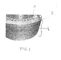
- stator cores constructed from sheets of laminated iron alloy, as shown in Fig. 1 .
- Individual laminations are punched from flat sheets of iron alloy using specially constructed dies with the necessary shape and with slots and teeth incorporated into them.
- Laminations made by this method are generally coated with a thin insulation layer and are then stacked together to form the laminated stator. It is important that the laminations are stacked in correct alignment and secured together for example by welding. The use of thin laminations prevents induced currents and losses that can adversely affect motor operation.
- stator core An alternative, but less widely-used, construction of a stator core involves the use of specially formed iron powder particles pressed into a mold to form the appropriate shape. To avoid losses and to prevent induced currents, special iron particles have to be used, for example iron powder coated with a thermal plastic material and comprising a phosphate layer.
- the aim of the present invention is to provide a stator that provides effective damping without substantially increasing the volume of the motor.
- the present invention goes away from conventional teaching and provides a stator having a construction that creates or allows induced currents thus providing a damping function.
- stator back iron of a solid piece of iron material or iron alloy as opposed to a stack of laminations or compressed composite powder.
- the cylindrical back iron can be molded, from solid iron or iron alloy material, in a single piece.
- individual circumferential segments can be formed of the solid metal, which are then fastened together to form a cylindrical back iron. This allows a better slot filling thus the thermal performance at low speed is improved. In addition, the manufacturing time and cost are reduced.
- Radially extending teeth are provided on the interior surface of the resulting stator back iron cylinder. Whilst the teeth could be formed by the process for molding the solid metal back iron, an alternative method involves bolting, welding or otherwise fastening the teeth to the inside surface of the cylinder.
- Pure iron can be used for the solid back iron component(s). Such a material has a high saturation point, high conductivity, low cost and is easy to manufacture. Other iron materials, iron alloys, etc. can, however, be used. For example, the level of damping of pure iron might be found to be too high and could be reduced using an alloy of iron.
- Fig. 1 shows how a conventional stator is formed by stacking a plurality of preshaped laminates 1.
- Each laminate 1 is formed as a flat circular plate or rim, defining the back iron 3", with a plurality of radially inwardly extending teeth 2. Insulation layers are provided between the laminations.
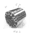
- the back iron 3" is formed from a solid cylinder of iron or iron alloy - i.e. a single piece of solid metal, or cylindrical circumferential segments of iron or iron alloy joined together to form a cylinder.
- the stator does not have the iron alloy laminations separated by insulation layers, or, for pressed powder versions, insulated coating on the alloy particles.
- the stator of the invention is essentially a fully metallic sold stator.
- the teeth 2" are then formed, preferably separately, and are attached to the inside of the cylinder, e.g. by screws or bolts 4, to extend radially inwards.
- the teeth could be formed integrally with the back iron or attached in another way e.g. by welding.
- the fully metallic solid stator creates or allows induced currents which provide the desired damping function in the stator itself.
Landscapes
- Engineering & Computer Science (AREA)
- Power Engineering (AREA)
- Iron Core Of Rotating Electric Machines (AREA)
Abstract
Description
- The present invention is concerned with a stator for an AC motor for an electromechanical actuator (EMA).
- Electromechanical actuators are used in a wide range of technology, for actuating system parts, for example in engine, machine, vehicle or aviation technology.
- An electromechanical actuator is driven by an AC motor comprising a stator assembly and a rotor.
- For some EMA applications such as flight control actuation, landing gear actuation, steering actuation, safety reasons imply that the motor shall oppose a drag torque, proportional to the revolution speed, in case the electric supply fails. This function is called damping function.
- Most conventional electric motors have stator cores constructed from sheets of laminated iron alloy, as shown in
Fig. 1 . Individual laminations are punched from flat sheets of iron alloy using specially constructed dies with the necessary shape and with slots and teeth incorporated into them. Laminations made by this method are generally coated with a thin insulation layer and are then stacked together to form the laminated stator. It is important that the laminations are stacked in correct alignment and secured together for example by welding. The use of thin laminations prevents induced currents and losses that can adversely affect motor operation. - An alternative, but less widely-used, construction of a stator core involves the use of specially formed iron powder particles pressed into a mold to form the appropriate shape. To avoid losses and to prevent induced currents, special iron particles have to be used, for example iron powder coated with a thermal plastic material and comprising a phosphate layer.
- In addition, regardless of which of these methods is used, it is necessary to provide additional componentry to the stator if damping of the motor is required.
- Existing systems use additional, or add-on damping devices to provide the required damping. These do, however, have significant negative impact on the overall volume and size of the motor.
- The aim of the present invention is to provide a stator that provides effective damping without substantially increasing the volume of the motor.
- As mentioned above, in the existing, conventional systems, steps are taken, conventionally by the use of laminations, or, otherwise, by using special powder compositions, to avoid or prevent induced currents.
- The present invention goes away from conventional teaching and provides a stator having a construction that creates or allows induced currents thus providing a damping function.
- This effect is provided by forming the stator back iron of a solid piece of iron material or iron alloy as opposed to a stack of laminations or compressed composite powder.
- The cylindrical back iron can be molded, from solid iron or iron alloy material, in a single piece. Alternatively, to simplify manufacturing and winding, individual circumferential segments can be formed of the solid metal, which are then fastened together to form a cylindrical back iron. This allows a better slot filling thus the thermal performance at low speed is improved. In addition, the manufacturing time and cost are reduced.
- Radially extending teeth are provided on the interior surface of the resulting stator back iron cylinder. Whilst the teeth could be formed by the process for molding the solid metal back iron, an alternative method involves bolting, welding or otherwise fastening the teeth to the inside surface of the cylinder.
- Pure iron can be used for the solid back iron component(s). Such a material has a high saturation point, high conductivity, low cost and is easy to manufacture. Other iron materials, iron alloys, etc. can, however, be used. For example, the level of damping of pure iron might be found to be too high and could be reduced using an alloy of iron.
- Thus, in the present invention, use is made of the behaviour of solid iron in inducing currents, as opposed to, like in the prior systems, taking steps to prevent or avoid induced currents. This enables a damping function to be provided using active parts of the motor, rather than providing an external device. This limits the overall volume of the motor, as well as reducing costs and manufacturing time.
- Preferred embodiments will now be described, by way of example only, with reference to the drawings:
-
Fig. 1 is a perspective view of a conventional, laminated, stator. -
Fig. 2 is a perspective view of a stator in accordance with the present invention. -
Fig. 1 shows how a conventional stator is formed by stacking a plurality of preshaped laminates 1. Each laminate 1 is formed as a flat circular plate or rim, defining theback iron 3", with a plurality of radially inwardly extendingteeth 2. Insulation layers are provided between the laminations. - In the stator of the present invention, as shown in
Fig. 2 , theback iron 3" is formed from a solid cylinder of iron or iron alloy - i.e. a single piece of solid metal, or cylindrical circumferential segments of iron or iron alloy joined together to form a cylinder. Thus, the stator does not have the iron alloy laminations separated by insulation layers, or, for pressed powder versions, insulated coating on the alloy particles. The stator of the invention is essentially a fully metallic sold stator. - The
teeth 2" are then formed, preferably separately, and are attached to the inside of the cylinder, e.g. by screws orbolts 4, to extend radially inwards. In other embodiments, the teeth could be formed integrally with the back iron or attached in another way e.g. by welding. - The fully metallic solid stator creates or allows induced currents which provide the desired damping function in the stator itself.
Claims (4)
- A stator for an electromechanical actuator motor, the stator comprising a cylindrical stator back plate formed of a single solid metal cylinder or a plurality of solid metal cylinder segments joined to form a cylinder, the metal comprising iron or iron alloy.
- The stator of claim 1 further comprising a plurality of radially inwardly extending teeth extending from the inner surface of the cylindrical stator back plate.
- The stator of claim 2 wherein the teeth are fastened to the stator back plate.
- A motor comprising
a stator as claimed in any preceding claim, and
a rotor rotatable relative to the stator.
Priority Applications (3)
| Application Number | Priority Date | Filing Date | Title |
|---|---|---|---|
| EP15165060.3A EP3086441A1 (en) | 2015-04-24 | 2015-04-24 | Stator for an ac motor for an electromechanical actuator |
| US15/135,857 US10141796B2 (en) | 2015-04-24 | 2016-04-22 | Stator for AC motor for an electromechanical actuator (EMA) |
| CA2928050A CA2928050A1 (en) | 2015-04-24 | 2016-04-22 | Stator for ac motor for an electromechanical actuator (ema) |
Applications Claiming Priority (1)
| Application Number | Priority Date | Filing Date | Title |
|---|---|---|---|
| EP15165060.3A EP3086441A1 (en) | 2015-04-24 | 2015-04-24 | Stator for an ac motor for an electromechanical actuator |
Publications (1)
| Publication Number | Publication Date |
|---|---|
| EP3086441A1 true EP3086441A1 (en) | 2016-10-26 |
Family
ID=53015576
Family Applications (1)
| Application Number | Title | Priority Date | Filing Date |
|---|---|---|---|
| EP15165060.3A Withdrawn EP3086441A1 (en) | 2015-04-24 | 2015-04-24 | Stator for an ac motor for an electromechanical actuator |
Country Status (3)
| Country | Link |
|---|---|
| US (1) | US10141796B2 (en) |
| EP (1) | EP3086441A1 (en) |
| CA (1) | CA2928050A1 (en) |
Citations (3)
| Publication number | Priority date | Publication date | Assignee | Title |
|---|---|---|---|---|
| JPS56110454A (en) * | 1980-01-31 | 1981-09-01 | Mitsubishi Electric Corp | Electric rotary machine |
| EP0921621A2 (en) * | 1993-06-14 | 1999-06-09 | Ecoair Corporation | Hybrid alternator with voltage regulator |
| US6163952A (en) * | 1996-11-06 | 2000-12-26 | Seiko Seiki Kabushiki Kaisha | Method of manufacturing armature of motor using hoop member |
Family Cites Families (5)
| Publication number | Priority date | Publication date | Assignee | Title |
|---|---|---|---|---|
| JP2001327135A (en) * | 2000-05-18 | 2001-11-22 | Mitsubishi Electric Corp | Rotating electric machine |
| CN101243594B (en) * | 2005-10-24 | 2012-07-04 | 松下电器产业株式会社 | Capacitor motor and process for producing the same |
| CN101375484A (en) * | 2006-01-24 | 2009-02-25 | 株式会社安川电机 | Split core for motor stator, permanent magnet synchronous motor, and punching method using split core punching die |
| US7459817B2 (en) * | 2006-08-15 | 2008-12-02 | Bombardier Transportation Gmbh | Semi-enclosed AC motor |
| WO2011048038A2 (en) * | 2009-10-21 | 2011-04-28 | Siemens Aktiengesellschaft | Generator |
-
2015
- 2015-04-24 EP EP15165060.3A patent/EP3086441A1/en not_active Withdrawn
-
2016
- 2016-04-22 US US15/135,857 patent/US10141796B2/en active Active
- 2016-04-22 CA CA2928050A patent/CA2928050A1/en not_active Abandoned
Patent Citations (3)
| Publication number | Priority date | Publication date | Assignee | Title |
|---|---|---|---|---|
| JPS56110454A (en) * | 1980-01-31 | 1981-09-01 | Mitsubishi Electric Corp | Electric rotary machine |
| EP0921621A2 (en) * | 1993-06-14 | 1999-06-09 | Ecoair Corporation | Hybrid alternator with voltage regulator |
| US6163952A (en) * | 1996-11-06 | 2000-12-26 | Seiko Seiki Kabushiki Kaisha | Method of manufacturing armature of motor using hoop member |
Also Published As
| Publication number | Publication date |
|---|---|
| US20160315507A1 (en) | 2016-10-27 |
| CA2928050A1 (en) | 2016-10-24 |
| US10141796B2 (en) | 2018-11-27 |
Similar Documents
| Publication | Publication Date | Title |
|---|---|---|
| CN111837314B (en) | Radial gap type rotating electrical machine | |
| US20210152040A1 (en) | Hybrid stator core component design for axial flux motor | |
| JP5864227B2 (en) | Rotor structure of electric motor | |
| KR101375456B1 (en) | Field pole members and methods of forming same for electrodynamic machines | |
| WO2019154731A1 (en) | Stator for rotary field machine having axial heat dissipation | |
| US20090183357A1 (en) | Magnetic powder metal composite core for electrical machines | |
| JP6868690B2 (en) | Rotating actuator | |
| EP2854256B1 (en) | Pole unit and stator assembly for a wind turbine generator, and methods of manufacturing the same | |
| JP2009195088A (en) | Rotating electric machine and manufacturing method thereof | |
| CN105490466B (en) | Laminate core and its manufacturing method | |
| JP6401605B2 (en) | Laminated body having dummy caulking, method for producing the same, and method for producing laminated iron core | |
| CN115700965B (en) | Hybrid stator core segment of axial flux motor | |
| EP3198708B1 (en) | Reluctance assisted external rotor pmsm | |
| JP6537296B2 (en) | Laminate having temporary caulking, method of manufacturing the same, and method of manufacturing laminated core | |
| JP2016123157A (en) | Laminate for rotor, method for producing the same, and method for producing the rotor | |
| CN102790458A (en) | Permanent magnet auxiliary synchronized reluctance motor rotor and manufacturing method thereof and motor | |
| US10141796B2 (en) | Stator for AC motor for an electromechanical actuator (EMA) | |
| JP6057777B2 (en) | Stator, hermetic compressor and rotary machine including the stator, and mold | |
| US8258671B2 (en) | Methods and apparatus for a continuous wound laminate rotor flux path | |
| JP5274496B2 (en) | Magnetic metal body and method for manufacturing rotating electrical machine using magnetic metal body | |
| US10404121B2 (en) | Electromechanical actuator damping | |
| EP3291414A2 (en) | Switched reluctance motor with axial laminated construction | |
| EP3133717B1 (en) | Axial air gap type electric motor | |
| US10263491B2 (en) | Electromechanical actuator damping | |
| EP3367539B1 (en) | Electrical machine laminations |
Legal Events
| Date | Code | Title | Description |
|---|---|---|---|
| PUAI | Public reference made under article 153(3) epc to a published international application that has entered the european phase |
Free format text: ORIGINAL CODE: 0009012 |
|
| AK | Designated contracting states |
Kind code of ref document: A1 Designated state(s): AL AT BE BG CH CY CZ DE DK EE ES FI FR GB GR HR HU IE IS IT LI LT LU LV MC MK MT NL NO PL PT RO RS SE SI SK SM TR |
|
| AX | Request for extension of the european patent |
Extension state: BA ME |
|
| STAA | Information on the status of an ep patent application or granted ep patent |
Free format text: STATUS: EXAMINATION IS IN PROGRESS |
|
| 17P | Request for examination filed |
Effective date: 20170426 |
|
| RBV | Designated contracting states (corrected) |
Designated state(s): AL AT BE BG CH CY CZ DE DK EE ES FI FR GB GR HR HU IE IS IT LI LT LU LV MC MK MT NL NO PL PT RO RS SE SI SK SM TR |
|
| 17Q | First examination report despatched |
Effective date: 20170526 |
|
| RAP1 | Party data changed (applicant data changed or rights of an application transferred) |
Owner name: GOODRICH ACTUATION SYSTEMS SAS |
|
| RAP1 | Party data changed (applicant data changed or rights of an application transferred) |
Owner name: GOODRICH ACTUATION SYSTEMS SAS |
|
| RAP3 | Party data changed (applicant data changed or rights of an application transferred) |
Owner name: GOODRICH ACTUATION SYSTEMS SAS |
|
| RAP3 | Party data changed (applicant data changed or rights of an application transferred) |
Owner name: GOODRICH ACTUATION SYSTEMS SAS |
|
| STAA | Information on the status of an ep patent application or granted ep patent |
Free format text: STATUS: THE APPLICATION IS DEEMED TO BE WITHDRAWN |
|
| 18D | Application deemed to be withdrawn |
Effective date: 20221101 |