EP3086084A1 - Machining a freely arranged or partially constrained composite part using a laser system - Google Patents
Machining a freely arranged or partially constrained composite part using a laser system Download PDFInfo
- Publication number
- EP3086084A1 EP3086084A1 EP16166444.6A EP16166444A EP3086084A1 EP 3086084 A1 EP3086084 A1 EP 3086084A1 EP 16166444 A EP16166444 A EP 16166444A EP 3086084 A1 EP3086084 A1 EP 3086084A1
- Authority
- EP
- European Patent Office
- Prior art keywords
- composite part
- manufacturing
- machining
- support surface
- skin
- Prior art date
- Legal status (The legal status is an assumption and is not a legal conclusion. Google has not performed a legal analysis and makes no representation as to the accuracy of the status listed.)
- Granted
Links
Images


Classifications
-
- G—PHYSICS
- G01—MEASURING; TESTING
- G01B—MEASURING LENGTH, THICKNESS OR SIMILAR LINEAR DIMENSIONS; MEASURING ANGLES; MEASURING AREAS; MEASURING IRREGULARITIES OF SURFACES OR CONTOURS
- G01B11/00—Measuring arrangements characterised by the use of optical techniques
- G01B11/24—Measuring arrangements characterised by the use of optical techniques for measuring contours or curvatures
-
- B—PERFORMING OPERATIONS; TRANSPORTING
- B23—MACHINE TOOLS; METAL-WORKING NOT OTHERWISE PROVIDED FOR
- B23K—SOLDERING OR UNSOLDERING; WELDING; CLADDING OR PLATING BY SOLDERING OR WELDING; CUTTING BY APPLYING HEAT LOCALLY, e.g. FLAME CUTTING; WORKING BY LASER BEAM
- B23K26/00—Working by laser beam, e.g. welding, cutting or boring
- B23K26/08—Devices involving relative movement between laser beam and workpiece
- B23K26/083—Devices involving movement of the workpiece in at least one axial direction
- B23K26/0853—Devices involving movement of the workpiece in at least in two axial directions, e.g. in a plane
-
- B—PERFORMING OPERATIONS; TRANSPORTING
- B23—MACHINE TOOLS; METAL-WORKING NOT OTHERWISE PROVIDED FOR
- B23K—SOLDERING OR UNSOLDERING; WELDING; CLADDING OR PLATING BY SOLDERING OR WELDING; CUTTING BY APPLYING HEAT LOCALLY, e.g. FLAME CUTTING; WORKING BY LASER BEAM
- B23K26/00—Working by laser beam, e.g. welding, cutting or boring
- B23K26/02—Positioning or observing the workpiece, e.g. with respect to the point of impact; Aligning, aiming or focusing the laser beam
- B23K26/03—Observing, e.g. monitoring, the workpiece
- B23K26/032—Observing, e.g. monitoring, the workpiece using optical means
-
- B—PERFORMING OPERATIONS; TRANSPORTING
- B23—MACHINE TOOLS; METAL-WORKING NOT OTHERWISE PROVIDED FOR
- B23K—SOLDERING OR UNSOLDERING; WELDING; CLADDING OR PLATING BY SOLDERING OR WELDING; CUTTING BY APPLYING HEAT LOCALLY, e.g. FLAME CUTTING; WORKING BY LASER BEAM
- B23K26/00—Working by laser beam, e.g. welding, cutting or boring
- B23K26/08—Devices involving relative movement between laser beam and workpiece
- B23K26/082—Scanning systems, i.e. devices involving movement of the laser beam relative to the laser head
-
- B—PERFORMING OPERATIONS; TRANSPORTING
- B23—MACHINE TOOLS; METAL-WORKING NOT OTHERWISE PROVIDED FOR
- B23K—SOLDERING OR UNSOLDERING; WELDING; CLADDING OR PLATING BY SOLDERING OR WELDING; CUTTING BY APPLYING HEAT LOCALLY, e.g. FLAME CUTTING; WORKING BY LASER BEAM
- B23K26/00—Working by laser beam, e.g. welding, cutting or boring
- B23K26/36—Removing material
- B23K26/38—Removing material by boring or cutting
- B23K26/382—Removing material by boring or cutting by boring
-
- F—MECHANICAL ENGINEERING; LIGHTING; HEATING; WEAPONS; BLASTING
- F02—COMBUSTION ENGINES; HOT-GAS OR COMBUSTION-PRODUCT ENGINE PLANTS
- F02C—GAS-TURBINE PLANTS; AIR INTAKES FOR JET-PROPULSION PLANTS; CONTROLLING FUEL SUPPLY IN AIR-BREATHING JET-PROPULSION PLANTS
- F02C7/00—Features, components parts, details or accessories, not provided for in, or of interest apart form groups F02C1/00 - F02C6/00; Air intakes for jet-propulsion plants
- F02C7/24—Heat or noise insulation
-
- B—PERFORMING OPERATIONS; TRANSPORTING
- B23—MACHINE TOOLS; METAL-WORKING NOT OTHERWISE PROVIDED FOR
- B23K—SOLDERING OR UNSOLDERING; WELDING; CLADDING OR PLATING BY SOLDERING OR WELDING; CUTTING BY APPLYING HEAT LOCALLY, e.g. FLAME CUTTING; WORKING BY LASER BEAM
- B23K2103/00—Materials to be soldered, welded or cut
- B23K2103/16—Composite materials, e.g. fibre reinforced
- B23K2103/166—Multilayered materials
- B23K2103/172—Multilayered materials wherein at least one of the layers is non-metallic
-
- F—MECHANICAL ENGINEERING; LIGHTING; HEATING; WEAPONS; BLASTING
- F05—INDEXING SCHEMES RELATING TO ENGINES OR PUMPS IN VARIOUS SUBCLASSES OF CLASSES F01-F04
- F05D—INDEXING SCHEME FOR ASPECTS RELATING TO NON-POSITIVE-DISPLACEMENT MACHINES OR ENGINES, GAS-TURBINES OR JET-PROPULSION PLANTS
- F05D2230/00—Manufacture
- F05D2230/10—Manufacture by removing material
- F05D2230/13—Manufacture by removing material using lasers
-
- F—MECHANICAL ENGINEERING; LIGHTING; HEATING; WEAPONS; BLASTING
- F05—INDEXING SCHEMES RELATING TO ENGINES OR PUMPS IN VARIOUS SUBCLASSES OF CLASSES F01-F04
- F05D—INDEXING SCHEME FOR ASPECTS RELATING TO NON-POSITIVE-DISPLACEMENT MACHINES OR ENGINES, GAS-TURBINES OR JET-PROPULSION PLANTS
- F05D2260/00—Function
- F05D2260/96—Preventing, counteracting or reducing vibration or noise
- F05D2260/963—Preventing, counteracting or reducing vibration or noise by Helmholtz resonators
-
- Y—GENERAL TAGGING OF NEW TECHNOLOGICAL DEVELOPMENTS; GENERAL TAGGING OF CROSS-SECTIONAL TECHNOLOGIES SPANNING OVER SEVERAL SECTIONS OF THE IPC; TECHNICAL SUBJECTS COVERED BY FORMER USPC CROSS-REFERENCE ART COLLECTIONS [XRACs] AND DIGESTS
- Y02—TECHNOLOGIES OR APPLICATIONS FOR MITIGATION OR ADAPTATION AGAINST CLIMATE CHANGE
- Y02T—CLIMATE CHANGE MITIGATION TECHNOLOGIES RELATED TO TRANSPORTATION
- Y02T50/00—Aeronautics or air transport
- Y02T50/60—Efficient propulsion technologies, e.g. for aircraft
Definitions
- This disclosure relates generally to laser machining and, more particularly, to perforating, cutting and/or otherwise machining composite material with a laser.
- An aircraft propulsion system may include components constructed from one or more structural acoustic panels.
- a typical acoustic panel includes a perforated face skin (or sheet), a back skin (or sheet) and at least one layer of porous core such as a honeycomb core.
- the porous core is positioned and bonded between the face skin and the back skin.
- the core, the face skin, and the back skin together form a plurality of acoustic chambers. These acoustic chambers are open to air outside of the face skin via perforations in the face skin.
- the acoustic chambers may serve to damp acoustic noise by facilitating generation of out of phase sound waves that destructively interfere with noise sound waves hitting the acoustic panel.
- the face skin and the back skin may each be made of composite material such as carbon fiber within an epoxy matrix.
- the porous core may be made from metal such as aluminum and bonded to the skins with an adhesive; e.g., the epoxy matrix.
- an adhesive e.g., the epoxy matrix.
- one or more components of an acoustic panel may alternatively be formed from one or more materials other than those described above.
- a manufacturing method in which a composite part is freely arranged on a support surface.
- the freely arranged composite part is scanned using a scanning system to provide command data.
- the freely arranged composite part is machined using a laser based on the command data.
- a manufacturing method in which a composite part is arranged with a guide on a support surface.
- the guide is configured to limit movement of the arranged composite part in a first direction while allowing movement of the arranged composite part in a second direction.
- the arranged composite part is scanned using a scanning system to provide command data.
- the arranged composite part is ablated using a laser based on the command data.
- the freely arranged composite part may be unattached to the support surface.
- the freely arranged composite part may be capable of sliding substantially unencumbered on the support surface.
- the arranging may include disposing the composite part on the support surface relative to at least one marking on the support surface such that the composite part is in a predetermined region and/or has a predetermined orientation.
- the scanning may include determining a location and/or an orientation of the freely arranged composite part.
- the scanning may include determining a characteristic about a geometry of the freely arranged composite part.
- the method may include comparing the determined characteristic to a predicted characteristic to provide comparison data.
- the command data may be provided based on the comparison data.
- the machining may include forming one or more apertures in and/or cutting the freely arranged composite part.
- the composite part may be configured as an acoustic panel for an aircraft propulsion system.
- the acoustic panel may include a porous core disposed between a pair of skins.
- the machining may include perforating one of the skins.
- the composite part may be configured as a skin of an acoustic panel for an aircraft propulsion system.
- the machining may include perforating the skin.
- the composite part may include reinforcement fibers within a polymeric matrix.
- the guide may be disposed within the composite part.
- the composite part may be disposed within the guide.
- the first direction may be a lateral direction and the second direction may be a vertical direction.
- the composite part may be configured as or include an acoustic panel skin for an aircraft propulsion system.
- the ablating may include perforating the skin.
- FIG. 1 is a block diagram of a system 20 for machining a composite part 22.
- This composite part 22 may be configured as a fiber-reinforced composite skin of an acoustic panel for an aircraft propulsion system; e.g., a turbofan or turbojet gas turbine engine.
- the composite part 22 may alternatively be configured as the acoustic panel itself or a partial bonded assembly thereof, which acoustic panel may include a porous (e.g., honeycomb) core sandwiched between and bonded to the skin and another skin.
- a porous e.g., honeycomb
- the machining system 20 may form one or more apertures 23 (e.g., through-holes or perforations) in the skin to provide that skin with a perforated configuration; i.e., to form the skin into a perforated skin.
- the machining system 20 may also or alternatively cut or trim the skin and/or the entire acoustic panel / partial bonded assembly thereof.
- the machining system 20 of the present disclosure is not limited to performing the foregoing machining operations nor to machining an acoustic panel or bonded assembly / element thereof.
- the composite part 22 may have a generally tubular geometry. With this geometry, the composite part 22 may be configured as or included in an inner barrel of an inlet for the aircraft propulsion system.
- the composite part 22, may alternatively have other geometries such as generally planar or arcuate geometries.
- the composite part 22 may be configured as or included in an apparatus other than that described above.
- the composite part 22, for example, may be configured as or for an inner fixed structure of the aircraft propulsion system.
- the composite part 22 may be configured as or for a sleeve or blocker door of a thrust reverser for the aircraft propulsion system.
- the machining system 20 of FIG. 1 includes a support 24, a manipulator 26, a scanning system 28 and a laser system 30.
- This machining system 20 also includes a controller 32 in signal communication (e.g., hardwired or wirelessly coupled) with one or more of the machining system components 26, 28 and 30.
- the support 24 may be configured as a stationary body with a generally flat, planar support surface 34.
- the support 24, for example, may be a flat granite slab, a metal table, a portion of a floor or other base surface, etc.
- the support 24 may also be configured such that the support surface 34 is substantially horizontal with respect to gravity. With such a configuration, the force of gravity and static friction may be utilized to hold the composite part 22 (see FIG. 1 ) in place on the support surface 34 without requiring use of tooling such as support fixtures, clamps, pins, fasteners, harnesses, etc.
- Such tooling is typically used in prior art methods to precisely locate a part and/or hold the part while a machining tool such as a drill press, a CNC machine or a media blasting device subjects that part to a force during machining.
- a machining tool such as a drill press, a CNC machine or a media blasting device subjects that part to a force during machining.
- the laser system 30 of the present disclosure does not touch the composite part 22 during machining and therefore applies very little or relatively insignificant lateral force against the composite part 22 during the machining. If the laser system 30 features a fume collection system, no part of the fume collection system should touch the part, either, in order to avoid moving it.
- the composite part 22 also need not be precisely located using tooling since the composite part 22 can be located by the scanning system 28.
- the composite part 22 may be freely arranged on the support surface 34.
- the composite part 22 may be unattached to the support 24 and/or capable of sliding laterally substantially unencumbered on the support surface 34 if engaged with a lateral force capable of overcoming static friction.
- the composite part 22 may also be capable of being lifted vertically generally without restriction.
- a composite part such as a fiber-reinforced acoustic panel may weigh between, for example, 20lbs (9 kg) and 100lbs (45 kg); however, the present disclosure is not limited to the foregoing exemplary embodiment.
- an individual or individuals may relatively quickly dispose the composite part 22 on the support surface 34 without needing to fix the composite part 22 to the support 24 using tooling. This may reduce set up time as well as eliminate costs associated with providing, maintaining, certifying and/or storing tooling.
- Set up time may be further reduced by configuring the support 24 with at least one marking 36 at a predetermined (known) position on the support surface 34.
- This marking 36 may be used for generally locating and/or orienting the composite part 22 on the support surface 34 within a predetermined region and/or with a predetermined orientation.
- the composite part 22 may be arranged within the marking 36 as illustrated in FIG. 3 .
- the composite part 22 may be arranged around the marking 36 as illustrated in FIG. 4 .
- the composite part 22 may also or alternatively be arranged on the marking 36.
- the marking 36 may be applied to the support surface 36.
- the marking 36 may be engraved into the support surface 34.
- the marking 36 may also or alternatively be displayed on the support surface 34 using, for example, a laser or another light source.
- the support 24 may be configured without any such markings.
- the markings 36 may also or alternatively be configured as or include one or more fiducials, also known as fiducial markers.
- the manipulator 26 is adapted to move at least one component (e.g., a scanner head 36) of the laser system 30 to various locations about (e.g., around, within, next to) the composite part 22.
- the manipulator 26 may also be configured to move part or all of the scanning system 28.
- the manipulator 26 of FIG. 1 for example, is configured as a multi-axis manipulator such as a six-axis robotic arm.
- the machining system 20 of the present disclosure is not limited to including any particular ones thereof.
- the scanning system 28 is adapted to determine location, orientation and/or geometry information about the composite part 22, which is used to provide command data.
- the scanning system 28, for example, may locate a feature or features on the composite part 22 such as, for example, tabs 38 and/or apertures 40 as shown in FIG. 5 .
- the scanning system 28 may determine the location of the composite part 22 as well as the orientation of the composite part 22 relative to the machining system 20.
- the scanning system 28 may also scan one or more areas of the composite part 22 to determine a characteristic about the geometry of the composite part 22.
- the scanning system 28 may determine a coordinate of a certain point or cluster of points on the located and orientated composite part 22, which point or cluster of points may be associated with where one or more of the apertures 23 is to be formed.
- the scanning system 28 may compare the determined characteristic (e.g., the determined coordinate(s)) to a predicted characteristic (e.g., predicted coordinate(s) for the point or cluster or points) to provide comparison data.
- This comparison data may be processed with machining data to adjust the machining data for deviations in the location, geometry and/or configuration of the actual composite part 22, which processed (e.g., adjusted) machining data forms the command data.
- This machining data may include, among other things, commands for locating the scanner head 36 a certain distance from the composite component during the machining. Where there are no deviations between the actual part 22 and the predicted part, corresponding distances of the command data and the machining data may be equal. However, where there are deviations between the actual part 22 and the predicted part, corresponding distances of the command data and the machining data may be different to account for the deviations between the actual composite part 22 and a predicted ideal composite part.
- processing device(s) configured with the scanning system 28.
- some or all of the processing may be performed by the controller 32.
- the scanning system 28 may be configured as or otherwise include a non-contact scanning device such as a laser measurement device, a white light measurement device, a blue light measurement device, etc.
- the scanning system 28 may also or alternatively be configured as or otherwise include a contact scanning device such as a coordinate measurement machine (CMM).
- CCM coordinate measurement machine
- various other types and configurations of scanning systems are known in the art, and the scanning system 28 of the present disclosure is not limited to including any particular ones thereof.
- the laser system 30 is adapted to form (ablate, cut) a plurality of the apertures 23 and/or other features in the composite part 22, which apertures 23 may be through-holes, dimples, grooves, channels, recessions, indentations, notches, etc.
- the laser system 30 includes a laser 42 optically coupled with the scanner head 36.
- the laser 42 may be configured as an infrared (IR) laser and/or pulsed laser.
- the lasers may also or alternatively be configured as a fiber laser.
- the laser 42 of FIG. 1 for example, is configured as an infrared pulsed fiber laser.
- the laser 42 includes a laser beam source 44 and a length of optical fiber 46, which optically couples the laser beam source 44 with the scanner head 36.
- the laser beam source 44 is adapted to generate a laser beam 48.
- the laser beam source 44 may be configured as or otherwise include, for example, a laser diode; e.g., an infrared laser diode.
- the optical fiber 46 is adapted to respectively direct the laser beam 48 generated by the laser beam source 44 to the scanner head 36.
- the optical fiber 46 may be configured as, for example, a length of flexible, hollow glass fiber capable of transmitting the laser beam 48 through reflectance.
- the scanner head 36 is adapted to receive the laser beam 48 from the optical fiber 46, and scan this laser beam 48 over at least a portion of the composite part 22.
- the scanner head 36 may also be adapted to adjust a focal length of the laser beam 48 during and/or before/after the scanning.
- the term "scan” may describe a process of directing a laser beam along a path over a part and/or to one or more discrete points on the part.
- the term “focal length” may describe a distance between the scanner head 36 and a focal point 50 (see FIG. 6 ) of the laser beam 48, which point is where the laser beam converges to its smallest diameters and greatest energy density, and which may be adjusted or set to be where the laser beam is incident with a part.
- the cutting or ablating process preferably is determined such that the composite part 22 is not excessively chemically altered or heat affected, which could cause contraction or expansion, strains and ultimately warping or other movement.
- the scanner head 36 of FIG. 6 includes a plurality of optical elements 52-55.
- One or more of these optical elements 52-55 may each be adapted to filter, focus and/or redirect the laser beam 48.
- the first element 52 for example, may be configured as a bending mirror.
- the first element 52 is adapted to direct the laser beam 48 output from the optical fiber 46 through the second element 53 and to the third element 54.
- the second element 53 may be configured as a lens, which translates back and forth between the optical elements 52 and 54.
- the second element 53 is adapted to change a focal length of the laser beam 48.
- the third element 54 may include one or more (e.g., single-axis) galvo mirrors 58.
- the third element 54 is adapted to direct the laser beam 48 through the fourth element 55 (see FIG. 6 ) to various points on the composite part 22 within a scan area; e.g., an area on the composite part 22 where the laser beam 48 may be directed without moving the scanner head 36.
- the fourth element 55 may be configured as a stationary focusing lens.
- the fourth element 55 is adapted to focus the laser beam 48 to the focal point 50.
- the controller 32 (e.g., a processing system) is adapted to signal one or more of the system components 26, 28 and 30 to perform at least a portion of the method described below.
- the controller 32 may be implemented with a combination of hardware and software.
- the hardware may include memory and one or more single-core and/or multi-core processors.
- the memory may be a non-transitory computer readable medium, and adapted to store the software (e.g., program instructions) for execution by the processors.
- the hardware may also include analog and/or digital circuitry other than that described above.
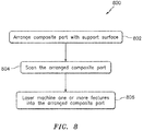
- FIG. 8 is a flow diagram of an exemplary method 800 for manufacturing an apparatus such as an acoustic panel as described above.
- a composite part such as the part 22 is arranged, scanned and machined.
- the composite part 22 is described below as the skin for the acoustic panel.
- the porous core and the skins may be bonded together after the skin (e.g., 22) has been perforated.
- the method of the present disclosure is not limited to such an embodiment.
- the composite part 22 may alternatively be configured as the entire bonded acoustic panel or a partial bonded assembly of the acoustic panel (e.g., the skin bonded to the porous core).
- the composite part 22 is stiff enough that it completely supports the weight of its own features without sagging, bending or otherwise moving before and during the laser perforation process.
- the laser perforation process for a skin of an acoustic panel removes as much as 10-30% of the skin volume.
- the skin must be stiff enough before and after perforation to prevent any sagging or bending.
- the composite part 22 is arranged with the support surface 34.
- the composite part 22 is arranged freely on the support surface 34, for example, relative to the marking 36 (see FIGS. 2-4 ).
- the force of gravity and/or static friction may be utilized to (e.g., solely) hold the composite part 22 in place on the support surface 34 without requiring use of tooling for example.
- the arranged composite part 22 is scanned using the scanning system 28 to provide command data.
- the scanning system 28 may determine a location and/or an orientation of the composite part 22.
- the scanning system 28 may use the determined location and/or orientation information in conjunction with data from a scan of the composite part 22 at a point or a cluster of points to determine a characteristic about the geometry of the arranged composite part 22 at that point or cluster of points.
- the determined characteristic may be compared to a predicted characteristic to provide comparison data.
- This comparison data may be processed with predetermined machining data to provide the command data, which command data may in general be similar to the machining data except for including adjustments to account for deviations between the actual scanned part and a theoretical ideal part model.
- one or more features are machined into the arranged composite part 22 using the laser system 30.
- the manipulator 26 may move the scanner head 36 to a certain position relative to the arranged composite part 22.
- the laser system 30 may subsequently direct the laser beam 48 against the composite part 22 to ablate a portion of the composite part material and form an aperture 23; e.g., a perforation.
- This step 806 may then be partially and/or fully repeated one or more times in order to perforate the composite part 22; e.g., the acoustic panel skin.
- the laser system 30 may also or alternatively be used to cut or trim the composite part 22 and/or form any other type of feature into the composite part 22.
- the laser system 30 will not touch and will not move the composite part 22 during these operations.
- the support 24 may be configured with at least one guide 60.
- This guide 60 may be a protrusion which projects out from the support surface 34 as illustrated in FIGS. 9-12 .
- the guide 60 may be an aperture (e.g., a recession or channel) that extends into the support 24 from the support surface 34.
- the guide 60 is configured to limit (e.g., significantly reduce or substantially prevent) movement of the composite part 22 in at least a first (e.g., lateral) direction while the part 22 is arranged with the guide 60 on the support surface 34.
- the guide 60 may be disposed within and laterally abutted against the composite part 22 as illustrated in FIG. 10 ; see also FIG. 9 .
- the composite part 22 may be disposed within and abutted against the guide 60 as illustrated in FIG. 12 ; see also FIG. 11 .
- the guide 60 limits movement in the first (e.g., lateral) direction
- the guide 60 allows for movement of the composite part 22 in a second (e.g., vertical) direction.
- the guide 60 may also serve to provide structure to the composite part 22 during machining. Such structure may be useful where, for example, the composite part 22 could potentially otherwise shift and/or deform as material is removed therefrom. However, similar to the freely arranged embodiment discussed above, no fixtures are required to hold or attached the composite part 22 to the support 24.
- the composite part 22 may be configured with a flange (e.g., an annular flange) at an end thereof which engages the support surface 34.
- a flange 62 may provide rigidity to the composite part 22 as well as further support for keeping the part 22 stable on the support surface 34.
- the composite part 22 generally describes the composite part 22 as being arranged by itself on the support surface 34.
- the composite part 22 may include its own support structure such as, for example, a cap, an internal frame and/or a base.
- a support structure may be configured to maintain the composite part 22 in a certain geometry and/or configuration.
- neither the supported composite part 22 nor the support structure are fixedly attached to the support 24.
- the supported composite part 22 may be freely arranged on the support surface 34.
- the supported composite part 22 may be arranged with the guide 60 on the support surface 34 and thereby partially (e.g., laterally but not vertically) constrained as described above.
- the composite part 22 may be formed of or otherwise include fiber reinforcement within a polymeric matrix.
- the fiber reinforcement may include, but is not limited to, fiberglass, carbon fibers, Aramid fibers (e.g., Kevlar® fibers), etc.
- the polymeric matrix may include epoxy resin or any other suitable thermoset or thermoplastic material.
- the composite part 22 of the present disclosure is not limited to being formed of or including any particular composite materials.
Abstract
Description
- This disclosure relates generally to laser machining and, more particularly, to perforating, cutting and/or otherwise machining composite material with a laser.
- An aircraft propulsion system may include components constructed from one or more structural acoustic panels. A typical acoustic panel includes a perforated face skin (or sheet), a back skin (or sheet) and at least one layer of porous core such as a honeycomb core. The porous core is positioned and bonded between the face skin and the back skin. The core, the face skin, and the back skin together form a plurality of acoustic chambers. These acoustic chambers are open to air outside of the face skin via perforations in the face skin. The acoustic chambers may serve to damp acoustic noise by facilitating generation of out of phase sound waves that destructively interfere with noise sound waves hitting the acoustic panel.
- In modern aircraft, the face skin and the back skin may each be made of composite material such as carbon fiber within an epoxy matrix. The porous core, on the other hand, may be made from metal such as aluminum and bonded to the skins with an adhesive; e.g., the epoxy matrix. Of course, one or more components of an acoustic panel may alternatively be formed from one or more materials other than those described above.
- One challenge in the construction of an acoustic panel is the perforation of the face skin. Thousands to millions of through-holes, for example, may need to be formed in the face skin. Often these holes are on the order of 0.050 inches (1.27 mm) in diameter down to much smaller diameters, and 10-30% of the face skin area is removed by the perforation. Improved manufacturing methods are desired to facilitate fast, inexpensive and accurate creation of these perforations.
- According to an aspect of the invention, a manufacturing method is provided in which a composite part is freely arranged on a support surface. The freely arranged composite part is scanned using a scanning system to provide command data. The freely arranged composite part is machined using a laser based on the command data.
- According to another aspect of the invention, a manufacturing method is provided in which a composite part is arranged with a guide on a support surface. The guide is configured to limit movement of the arranged composite part in a first direction while allowing movement of the arranged composite part in a second direction. The arranged composite part is scanned using a scanning system to provide command data. The arranged composite part is ablated using a laser based on the command data.
- The freely arranged composite part may be unattached to the support surface.
- The freely arranged composite part may be capable of sliding substantially unencumbered on the support surface.
- The arranging may include disposing the composite part on the support surface relative to at least one marking on the support surface such that the composite part is in a predetermined region and/or has a predetermined orientation.
- The scanning may include determining a location and/or an orientation of the freely arranged composite part.
- The scanning may include determining a characteristic about a geometry of the freely arranged composite part.
- The method may include comparing the determined characteristic to a predicted characteristic to provide comparison data. The command data may be provided based on the comparison data.
- The machining may include forming one or more apertures in and/or cutting the freely arranged composite part.
- The composite part may be configured as an acoustic panel for an aircraft propulsion system. The acoustic panel may include a porous core disposed between a pair of skins. The machining may include perforating one of the skins.
- The composite part may be configured as a skin of an acoustic panel for an aircraft propulsion system. The machining may include perforating the skin.
- The composite part may include reinforcement fibers within a polymeric matrix.
- The guide may be disposed within the composite part.
- The composite part may be disposed within the guide.
- The first direction may be a lateral direction and the second direction may be a vertical direction.
- The composite part may be configured as or include an acoustic panel skin for an aircraft propulsion system. The ablating may include perforating the skin.
- The foregoing features and the operation of the invention will become more apparent in light of the following description and the accompanying drawings.
-
-
FIG. 1 is a block diagram of a system for machining a composite part. -
FIG. 2 is a perspective illustration of a support for a composite part. -
FIG. 3 is a topside illustration of a composite part arranged with a support. -
FIG. 4 is a topside illustration of a composite part arranged with a support. -
FIG. 5 is a perspective illustration of a composite part arranged with a support. -
FIG. 6 is a block diagram of a scanner head for a laser system. -
FIG. 7 is a block diagram of an optical element with galvo mirrors for the scanner head ofFIG. 6 . -
FIG. 8 is a flow diagram of a method for manufacturing an apparatus such as an acoustic panel with a composite part. -
FIG. 9 is a perspective illustration of a support for a composite part. -
FIG. 10 is a topside illustration of the composite part arranged with the support ofFIG. 9 . -
FIG. 11 is a perspective illustration of a support for a composite part. -
FIG. 12 is a topside illustration of the composite part arranged with the support ofFIG. 11 . -
FIG. 13 is a perspective illustration of another composite part arranged with a support. -
FIG. 1 is a block diagram of asystem 20 for machining acomposite part 22. Thiscomposite part 22 may be configured as a fiber-reinforced composite skin of an acoustic panel for an aircraft propulsion system; e.g., a turbofan or turbojet gas turbine engine. Thecomposite part 22 may alternatively be configured as the acoustic panel itself or a partial bonded assembly thereof, which acoustic panel may include a porous (e.g., honeycomb) core sandwiched between and bonded to the skin and another skin. In the foregoing exemplary embodiments, themachining system 20 may form one or more apertures 23 (e.g., through-holes or perforations) in the skin to provide that skin with a perforated configuration; i.e., to form the skin into a perforated skin. Themachining system 20 may also or alternatively cut or trim the skin and/or the entire acoustic panel / partial bonded assembly thereof. Themachining system 20 of the present disclosure, however, is not limited to performing the foregoing machining operations nor to machining an acoustic panel or bonded assembly / element thereof. - Briefly, the
composite part 22 may have a generally tubular geometry. With this geometry, thecomposite part 22 may be configured as or included in an inner barrel of an inlet for the aircraft propulsion system. Thecomposite part 22, of course, may alternatively have other geometries such as generally planar or arcuate geometries. Furthermore, thecomposite part 22 may be configured as or included in an apparatus other than that described above. Thecomposite part 22, for example, may be configured as or for an inner fixed structure of the aircraft propulsion system. In another example, thecomposite part 22 may be configured as or for a sleeve or blocker door of a thrust reverser for the aircraft propulsion system. - The
machining system 20 ofFIG. 1 includes asupport 24, amanipulator 26, ascanning system 28 and alaser system 30. Thismachining system 20 also includes acontroller 32 in signal communication (e.g., hardwired or wirelessly coupled) with one or more of themachining system components - Referring to
FIG. 2 , thesupport 24 may be configured as a stationary body with a generally flat,planar support surface 34. Thesupport 24, for example, may be a flat granite slab, a metal table, a portion of a floor or other base surface, etc. Thesupport 24 may also be configured such that thesupport surface 34 is substantially horizontal with respect to gravity. With such a configuration, the force of gravity and static friction may be utilized to hold the composite part 22 (seeFIG. 1 ) in place on thesupport surface 34 without requiring use of tooling such as support fixtures, clamps, pins, fasteners, harnesses, etc. Such tooling is typically used in prior art methods to precisely locate a part and/or hold the part while a machining tool such as a drill press, a CNC machine or a media blasting device subjects that part to a force during machining. Thelaser system 30 of the present disclosure, however, does not touch thecomposite part 22 during machining and therefore applies very little or relatively insignificant lateral force against thecomposite part 22 during the machining. If thelaser system 30 features a fume collection system, no part of the fume collection system should touch the part, either, in order to avoid moving it. Thecomposite part 22 also need not be precisely located using tooling since thecomposite part 22 can be located by thescanning system 28. - As described above, the
composite part 22 may be freely arranged on thesupport surface 34. For example, thecomposite part 22 may be unattached to thesupport 24 and/or capable of sliding laterally substantially unencumbered on thesupport surface 34 if engaged with a lateral force capable of overcoming static friction. Thecomposite part 22 may also be capable of being lifted vertically generally without restriction. Note: a composite part such as a fiber-reinforced acoustic panel may weigh between, for example, 20lbs (9 kg) and 100lbs (45 kg); however, the present disclosure is not limited to the foregoing exemplary embodiment. - With the foregoing free arrangement, an individual or individuals may relatively quickly dispose the
composite part 22 on thesupport surface 34 without needing to fix thecomposite part 22 to thesupport 24 using tooling. This may reduce set up time as well as eliminate costs associated with providing, maintaining, certifying and/or storing tooling. - Set up time may be further reduced by configuring the
support 24 with at least one marking 36 at a predetermined (known) position on thesupport surface 34. This marking 36 may be used for generally locating and/or orienting thecomposite part 22 on thesupport surface 34 within a predetermined region and/or with a predetermined orientation. For example, thecomposite part 22 may be arranged within the marking 36 as illustrated inFIG. 3 . Thecomposite part 22 may be arranged around the marking 36 as illustrated inFIG. 4 . Thecomposite part 22 may also or alternatively be arranged on the marking 36. The marking 36may be applied to thesupport surface 36. The marking 36 may be engraved into thesupport surface 34. The marking 36 may also or alternatively be displayed on thesupport surface 34 using, for example, a laser or another light source. Of course, in other embodiments, thesupport 24 may be configured without any such markings. For example, themarkings 36 may also or alternatively be configured as or include one or more fiducials, also known as fiducial markers. - Referring again to
FIG. 1 , themanipulator 26 is adapted to move at least one component (e.g., a scanner head 36) of thelaser system 30 to various locations about (e.g., around, within, next to) thecomposite part 22. Themanipulator 26 may also be configured to move part or all of thescanning system 28. Themanipulator 26 ofFIG. 1 , for example, is configured as a multi-axis manipulator such as a six-axis robotic arm. Of course, various other types and configurations of manipulators are known in the art, and themachining system 20 of the present disclosure is not limited to including any particular ones thereof. - The
scanning system 28 is adapted to determine location, orientation and/or geometry information about thecomposite part 22, which is used to provide command data. Thescanning system 28, for example, may locate a feature or features on thecomposite part 22 such as, for example,tabs 38 and/orapertures 40 as shown inFIG. 5 . By processing data indicative of the locations of at least some of thefeatures scanning system 28 may determine the location of thecomposite part 22 as well as the orientation of thecomposite part 22 relative to themachining system 20. - The
scanning system 28 may also scan one or more areas of thecomposite part 22 to determine a characteristic about the geometry of thecomposite part 22. Thescanning system 28, for example, may determine a coordinate of a certain point or cluster of points on the located and orientatedcomposite part 22, which point or cluster of points may be associated with where one or more of theapertures 23 is to be formed. Thescanning system 28 may compare the determined characteristic (e.g., the determined coordinate(s)) to a predicted characteristic (e.g., predicted coordinate(s) for the point or cluster or points) to provide comparison data. This comparison data may be processed with machining data to adjust the machining data for deviations in the location, geometry and/or configuration of the actualcomposite part 22, which processed (e.g., adjusted) machining data forms the command data. This machining data may include, among other things, commands for locating the scanner head 36 a certain distance from the composite component during the machining. Where there are no deviations between theactual part 22 and the predicted part, corresponding distances of the command data and the machining data may be equal. However, where there are deviations between theactual part 22 and the predicted part, corresponding distances of the command data and the machining data may be different to account for the deviations between the actualcomposite part 22 and a predicted ideal composite part. - Some or all of the data processing described above may be performed by processing device(s) configured with the
scanning system 28. Alternatively, some or all of the processing may be performed by thecontroller 32. - The
scanning system 28 may be configured as or otherwise include a non-contact scanning device such as a laser measurement device, a white light measurement device, a blue light measurement device, etc. Thescanning system 28 may also or alternatively be configured as or otherwise include a contact scanning device such as a coordinate measurement machine (CMM). Of course, various other types and configurations of scanning systems are known in the art, and thescanning system 28 of the present disclosure is not limited to including any particular ones thereof. - The
laser system 30 is adapted to form (ablate, cut) a plurality of theapertures 23 and/or other features in thecomposite part 22, which apertures 23 may be through-holes, dimples, grooves, channels, recessions, indentations, notches, etc. Thelaser system 30 includes alaser 42 optically coupled with thescanner head 36. - The
laser 42 may be configured as an infrared (IR) laser and/or pulsed laser. The lasers may also or alternatively be configured as a fiber laser. Thelaser 42 ofFIG. 1 , for example, is configured as an infrared pulsed fiber laser. Thelaser 42 includes alaser beam source 44 and a length ofoptical fiber 46, which optically couples thelaser beam source 44 with thescanner head 36. - The
laser beam source 44 is adapted to generate alaser beam 48. Thelaser beam source 44 may be configured as or otherwise include, for example, a laser diode; e.g., an infrared laser diode. - The
optical fiber 46 is adapted to respectively direct thelaser beam 48 generated by thelaser beam source 44 to thescanner head 36. Theoptical fiber 46 may be configured as, for example, a length of flexible, hollow glass fiber capable of transmitting thelaser beam 48 through reflectance. - The
scanner head 36 is adapted to receive thelaser beam 48 from theoptical fiber 46, and scan thislaser beam 48 over at least a portion of thecomposite part 22. Thescanner head 36 may also be adapted to adjust a focal length of thelaser beam 48 during and/or before/after the scanning. The term "scan" may describe a process of directing a laser beam along a path over a part and/or to one or more discrete points on the part. The term "focal length" may describe a distance between thescanner head 36 and a focal point 50 (seeFIG. 6 ) of thelaser beam 48, which point is where the laser beam converges to its smallest diameters and greatest energy density, and which may be adjusted or set to be where the laser beam is incident with a part. The cutting or ablating process preferably is determined such that thecomposite part 22 is not excessively chemically altered or heat affected, which could cause contraction or expansion, strains and ultimately warping or other movement. - The
scanner head 36 ofFIG. 6 includes a plurality of optical elements 52-55. One or more of these optical elements 52-55 may each be adapted to filter, focus and/or redirect thelaser beam 48. Thefirst element 52, for example, may be configured as a bending mirror. Thefirst element 52 is adapted to direct thelaser beam 48 output from theoptical fiber 46 through thesecond element 53 and to thethird element 54. Thesecond element 53 may be configured as a lens, which translates back and forth between theoptical elements second element 53 is adapted to change a focal length of thelaser beam 48. Referring toFIG. 7 , thethird element 54 may include one or more (e.g., single-axis) galvo mirrors 58. Thethird element 54 is adapted to direct thelaser beam 48 through the fourth element 55 (seeFIG. 6 ) to various points on thecomposite part 22 within a scan area; e.g., an area on thecomposite part 22 where thelaser beam 48 may be directed without moving thescanner head 36. Referring again toFIG. 6 , thefourth element 55 may be configured as a stationary focusing lens. Thefourth element 55 is adapted to focus thelaser beam 48 to thefocal point 50. - Referring again to
FIG. 1 , the controller 32 (e.g., a processing system) is adapted to signal one or more of thesystem components controller 32 may be implemented with a combination of hardware and software. The hardware may include memory and one or more single-core and/or multi-core processors. The memory may be a non-transitory computer readable medium, and adapted to store the software (e.g., program instructions) for execution by the processors. The hardware may also include analog and/or digital circuitry other than that described above. -
FIG. 8 is a flow diagram of anexemplary method 800 for manufacturing an apparatus such as an acoustic panel as described above. During thismethod 800, a composite part such as thepart 22 is arranged, scanned and machined. For ease of description, thecomposite part 22 is described below as the skin for the acoustic panel. In such an embodiment, the porous core and the skins may be bonded together after the skin (e.g., 22) has been perforated. However, the method of the present disclosure is not limited to such an embodiment. For example, thecomposite part 22 may alternatively be configured as the entire bonded acoustic panel or a partial bonded assembly of the acoustic panel (e.g., the skin bonded to the porous core). Preferably, thecomposite part 22 is stiff enough that it completely supports the weight of its own features without sagging, bending or otherwise moving before and during the laser perforation process. The laser perforation process for a skin of an acoustic panel removes as much as 10-30% of the skin volume. The skin must be stiff enough before and after perforation to prevent any sagging or bending. - In
step 802, thecomposite part 22 is arranged with thesupport surface 34. In particular, thecomposite part 22 is arranged freely on thesupport surface 34, for example, relative to the marking 36 (seeFIGS. 2-4 ). As described above, in such a free arrangement, the force of gravity and/or static friction may be utilized to (e.g., solely) hold thecomposite part 22 in place on thesupport surface 34 without requiring use of tooling for example. - In
step 804, the arrangedcomposite part 22 is scanned using thescanning system 28 to provide command data. Thescanning system 28, for example, may determine a location and/or an orientation of thecomposite part 22. Thescanning system 28 may use the determined location and/or orientation information in conjunction with data from a scan of thecomposite part 22 at a point or a cluster of points to determine a characteristic about the geometry of the arrangedcomposite part 22 at that point or cluster of points. The determined characteristic may be compared to a predicted characteristic to provide comparison data. This comparison data may be processed with predetermined machining data to provide the command data, which command data may in general be similar to the machining data except for including adjustments to account for deviations between the actual scanned part and a theoretical ideal part model. - In
step 806, one or more features are machined into the arrangedcomposite part 22 using thelaser system 30. Operating based on the command data, for example, themanipulator 26 may move thescanner head 36 to a certain position relative to the arrangedcomposite part 22. Thelaser system 30 may subsequently direct thelaser beam 48 against thecomposite part 22 to ablate a portion of the composite part material and form anaperture 23; e.g., a perforation. Thisstep 806 may then be partially and/or fully repeated one or more times in order to perforate thecomposite part 22; e.g., the acoustic panel skin. Thelaser system 30 may also or alternatively be used to cut or trim thecomposite part 22 and/or form any other type of feature into thecomposite part 22. Preferably, thelaser system 30 will not touch and will not move thecomposite part 22 during these operations. - Referring to
FIGS. 9-12 , in some embodiments, thesupport 24 may be configured with at least oneguide 60. Thisguide 60 may be a protrusion which projects out from thesupport surface 34 as illustrated inFIGS. 9-12 . Alternatively, theguide 60 may be an aperture (e.g., a recession or channel) that extends into thesupport 24 from thesupport surface 34. - The
guide 60 is configured to limit (e.g., significantly reduce or substantially prevent) movement of thecomposite part 22 in at least a first (e.g., lateral) direction while thepart 22 is arranged with theguide 60 on thesupport surface 34. Theguide 60, for example, may be disposed within and laterally abutted against thecomposite part 22 as illustrated inFIG. 10 ; see alsoFIG. 9 . In another example, thecomposite part 22 may be disposed within and abutted against theguide 60 as illustrated inFIG. 12 ; see alsoFIG. 11 . While theguide 60 limits movement in the first (e.g., lateral) direction, theguide 60 allows for movement of thecomposite part 22 in a second (e.g., vertical) direction. This enables an individual or individuals to relatively quickly arrange thecomposite part 22 with thesupport 24 at a predetermined location and/or with a predetermined orientation. Theguide 60 may also serve to provide structure to thecomposite part 22 during machining. Such structure may be useful where, for example, thecomposite part 22 could potentially otherwise shift and/or deform as material is removed therefrom. However, similar to the freely arranged embodiment discussed above, no fixtures are required to hold or attached thecomposite part 22 to thesupport 24. - Referring to
FIG. 13 , in some embodiments, thecomposite part 22 may be configured with a flange (e.g., an annular flange) at an end thereof which engages thesupport surface 34. Such aflange 62 may provide rigidity to thecomposite part 22 as well as further support for keeping thepart 22 stable on thesupport surface 34. - The foregoing disclosure generally describes the
composite part 22 as being arranged by itself on thesupport surface 34. However, in some embodiments, thecomposite part 22 may include its own support structure such as, for example, a cap, an internal frame and/or a base. Such a support structure may be configured to maintain thecomposite part 22 in a certain geometry and/or configuration. Similar to the disclosure above, however, neither the supportedcomposite part 22 nor the support structure are fixedly attached to thesupport 24. Rather, the supportedcomposite part 22 may be freely arranged on thesupport surface 34. Alternatively, the supportedcomposite part 22 may be arranged with theguide 60 on thesupport surface 34 and thereby partially (e.g., laterally but not vertically) constrained as described above. - In some embodiments, the
composite part 22 may be formed of or otherwise include fiber reinforcement within a polymeric matrix. The fiber reinforcement may include, but is not limited to, fiberglass, carbon fibers, Aramid fibers (e.g., Kevlar® fibers), etc. The polymeric matrix may include epoxy resin or any other suitable thermoset or thermoplastic material. Of course, thecomposite part 22 of the present disclosure is not limited to being formed of or including any particular composite materials. - While various embodiments of the present invention have been disclosed, it will be apparent to those of ordinary skill in the art that many more embodiments and implementations are possible within the scope of the invention. For example, the present invention as described herein includes several aspects and embodiments that include particular features. Although these features may be described individually, it is within the scope of the present invention that some or all of these features may be combined with any one of the aspects and remain within the scope of the invention. Accordingly, the present invention is not to be restricted except in light of the attached claims and their equivalents.
Claims (15)
- A manufacturing method, comprising:arranging a composite part (22) freely on a support surface (34);scanning the freely arranged composite part (22) using a scanning system (28) to provide command data; andmachining the freely arranged composite part (22) using a laser (42) based on the command data.
- The manufacturing method of claim 1, wherein the freely arranged composite part (22) is unattached to the support surface (34).
- The manufacturing method of claim 1 or 2, wherein the freely arranged composite part (22) is capable of sliding substantially unencumbered on the support surface (34).
- The manufacturing method of claim 1, 2 or 3, wherein the arranging comprises disposing the composite part (22) on the support surface (34) relative to a marking (36) on the support surface (34) such that the composite part (22) is in a predetermined region and/or has a predetermined orientation.
- The manufacturing method of any preceding claim, wherein the scanning comprises determining a location and/or an orientation of the freely arranged composite part (22).
- The manufacturing method of any preceding claim, wherein the scanning comprises determining a characteristic about a geometry of the freely arranged composite part (22).
- The manufacturing method of claim 6, further comprising comparing the determined characteristic to a predicted characteristic to provide comparison data, wherein the command data is provided based on the comparison data.
- The manufacturing method of any preceding claim, wherein the machining comprises forming one or more apertures (40) in and/or cutting the freely arranged composite part (22).
- The manufacturing method of any preceding claim, wherein
the composite part (22) is configured as an acoustic panel for an aircraft propulsion system;
the acoustic panel comprises a porous core disposed between a pair of skins; and
the machining comprises perforating one of the skins. - The manufacturing method of any of claims 1-8, wherein
the composite part (22) is configured as a skin of an acoustic panel for an aircraft propulsion system; and
the machining comprises perforating the skin. - The manufacturing method of any preceding claim, wherein the composite part (22) comprises reinforcement fibers within a polymeric matrix.
- The manufacturing method of claim 1, wherein:the composite part (22) is arranged with a guide on the support surface, wherein the guide (60) is configured to limit movement of the arranged composite part (22) in a first direction while allowing movement of the arranged composite part (22) in a second direction; andthe machining comprises ablating the arranged composite part (22) using a laser (42) based on the command data.
- The manufacturing method of claim 12, wherein the guide (60) is disposed within the composite part (22).
- The manufacturing method of claim 12 or 13, wherein the first direction is a lateral direction and the second direction is a vertical direction.
- The manufacturing method of claim 12, 13 or 14, wherein
the composite part (22) comprises an acoustic panel skin for an aircraft propulsion system; and
the ablating comprises perforating the skin.
Applications Claiming Priority (1)
| Application Number | Priority Date | Filing Date | Title |
|---|---|---|---|
| US14/692,360 US20160311062A1 (en) | 2015-04-21 | 2015-04-21 | Machining a freely arranged or partially constrained composite part using a laser system |
Publications (2)
| Publication Number | Publication Date |
|---|---|
| EP3086084A1 true EP3086084A1 (en) | 2016-10-26 |
| EP3086084B1 EP3086084B1 (en) | 2020-12-09 |
Family
ID=56087073
Family Applications (1)
| Application Number | Title | Priority Date | Filing Date |
|---|---|---|---|
| EP16166444.6A Active EP3086084B1 (en) | 2015-04-21 | 2016-04-21 | Machining a freely arranged composite part using a laser system |
Country Status (2)
| Country | Link |
|---|---|
| US (1) | US20160311062A1 (en) |
| EP (1) | EP3086084B1 (en) |
Families Citing this family (2)
| Publication number | Priority date | Publication date | Assignee | Title |
|---|---|---|---|---|
| US10275722B2 (en) | 2017-04-19 | 2019-04-30 | The Nordam Group, Inc. | Self recognition CNC machining |
| IT201800003770A1 (en) * | 2018-03-20 | 2019-09-20 | Mecc Pi Erre S R L Di Pederzoli Ruggero & C | PLANT FOR THE EXECUTION OF OPERATIONS FOR THE REALIZATION OF A PIECE STARTING FROM A CAST |
Citations (3)
| Publication number | Priority date | Publication date | Assignee | Title |
|---|---|---|---|---|
| US4188544A (en) * | 1977-08-22 | 1980-02-12 | Weyerhaeuser Company | Method and apparatus for automatically processing a workpiece employing calibrated scanning |
| GB2478312A (en) * | 2010-03-02 | 2011-09-07 | Gkn Aerospace Services Ltd | Manufacturing composite acoustic panels |
| WO2014109120A1 (en) * | 2013-01-10 | 2014-07-17 | 三菱重工業株式会社 | Three-dimensional laser processing machine |
Family Cites Families (6)
| Publication number | Priority date | Publication date | Assignee | Title |
|---|---|---|---|---|
| US4761561A (en) * | 1985-11-27 | 1988-08-02 | Nippon Kogaku K.K. | Laser beam scanning pattern generation system with positional and dimensional error correction |
| US4850093A (en) * | 1987-02-09 | 1989-07-25 | Grumman Aerospace Corporation | Method of making an acoustic attenuating liner |
| FR2643004B1 (en) * | 1989-02-13 | 1994-06-17 | Hurel Dubois Avions | METHOD FOR DRILLING A PLATE WITH VERY LARGE DENSITY OF HOLES AND ANY CONFIGURATION, AND RESULTING PRODUCTS |
| US5216808A (en) * | 1990-11-13 | 1993-06-08 | General Electric Company | Method for making or repairing a gas turbine engine component |
| US6317980B2 (en) * | 1997-10-20 | 2001-11-20 | Mitek Holdings, Inc. | Laser jigging system for assembly of trusses and method of use |
| JP2003251464A (en) * | 2002-03-01 | 2003-09-09 | Koike Sanso Kogyo Co Ltd | Cutter |
-
2015
- 2015-04-21 US US14/692,360 patent/US20160311062A1/en not_active Abandoned
-
2016
- 2016-04-21 EP EP16166444.6A patent/EP3086084B1/en active Active
Patent Citations (3)
| Publication number | Priority date | Publication date | Assignee | Title |
|---|---|---|---|---|
| US4188544A (en) * | 1977-08-22 | 1980-02-12 | Weyerhaeuser Company | Method and apparatus for automatically processing a workpiece employing calibrated scanning |
| GB2478312A (en) * | 2010-03-02 | 2011-09-07 | Gkn Aerospace Services Ltd | Manufacturing composite acoustic panels |
| WO2014109120A1 (en) * | 2013-01-10 | 2014-07-17 | 三菱重工業株式会社 | Three-dimensional laser processing machine |
Also Published As
| Publication number | Publication date |
|---|---|
| US20160311062A1 (en) | 2016-10-27 |
| EP3086084B1 (en) | 2020-12-09 |
Similar Documents
| Publication | Publication Date | Title |
|---|---|---|
| US4973819A (en) | Gantry with a laser mounted numerically controlled carriage | |
| US5883356A (en) | Laser scoring process and apparatus | |
| US10843292B2 (en) | Initial distance approach for laser processing | |
| EP3050665B1 (en) | Collecting / removing byproducts of laser ablation | |
| EP2915620B1 (en) | Forming one or more apertures in a fiber-reinforced composite object with a laser | |
| JP6159428B2 (en) | Laser processing system and method | |
| EP1958726A1 (en) | Scanning mechanism, method of machining workpiece, and machine tool | |
| EP3086084B1 (en) | Machining a freely arranged composite part using a laser system | |
| IT201600070441A1 (en) | Process for laser processing of a metal material with high-dynamic control of the axes of movement of the laser beam along a predetermined processing path, as well as a machine and computer program for carrying out such a process. | |
| JP2005230886A5 (en) | ||
| JP6090463B2 (en) | Work route creation device, work route creation method, work route creation program, and recording medium | |
| JPWO2013121818A1 (en) | Laser processing machine | |
| CN112264722A (en) | Laser micropore machining equipment and machining method suitable for thin-wall parts | |
| JP2000334594A (en) | Laser beam machine and method for laser beam machining | |
| CN115213568A (en) | Composite laser processing system and processing method | |
| EP3263293B1 (en) | Analysis of end effector operations by a robot | |
| JP6442466B2 (en) | Ceramic matrix composite (CMC) sheet forming system and method | |
| US9855626B2 (en) | Forming a pattern of apertures in an object with a plurality of laser beams | |
| JP5320682B2 (en) | Laser processing apparatus and laser processing method | |
| JP4332597B2 (en) | Drilling device | |
| JP2008221223A (en) | Laser beam welding method and apparatus | |
| JP2003170336A (en) | Machine tool having flexible structure | |
| JPH11267860A (en) | Marking device | |
| JP2007237231A (en) | Apparatus, system and method for drilling | |
| KR20230101297A (en) | Manufacturing system and method for a cowl cross |
Legal Events
| Date | Code | Title | Description |
|---|---|---|---|
| PUAI | Public reference made under article 153(3) epc to a published international application that has entered the european phase |
Free format text: ORIGINAL CODE: 0009012 |
|
| AK | Designated contracting states |
Kind code of ref document: A1 Designated state(s): AL AT BE BG CH CY CZ DE DK EE ES FI FR GB GR HR HU IE IS IT LI LT LU LV MC MK MT NL NO PL PT RO RS SE SI SK SM TR |
|
| AX | Request for extension of the european patent |
Extension state: BA ME |
|
| STAA | Information on the status of an ep patent application or granted ep patent |
Free format text: STATUS: REQUEST FOR EXAMINATION WAS MADE |
|
| 17P | Request for examination filed |
Effective date: 20170425 |
|
| RBV | Designated contracting states (corrected) |
Designated state(s): AL AT BE BG CH CY CZ DE DK EE ES FI FR GB GR HR HU IE IS IT LI LT LU LV MC MK MT NL NO PL PT RO RS SE SI SK SM TR |
|
| STAA | Information on the status of an ep patent application or granted ep patent |
Free format text: STATUS: EXAMINATION IS IN PROGRESS |
|
| 17Q | First examination report despatched |
Effective date: 20180329 |
|
| RIC1 | Information provided on ipc code assigned before grant |
Ipc: B23K 26/08 20140101ALI20190809BHEP Ipc: G01B 11/24 20060101AFI20190809BHEP Ipc: F02C 7/045 20060101ALI20190809BHEP Ipc: B23K 103/16 20060101ALN20190809BHEP Ipc: B23K 26/03 20060101ALI20190809BHEP Ipc: B23K 26/382 20140101ALI20190809BHEP Ipc: B23K 26/082 20140101ALI20190809BHEP Ipc: B23K 26/38 20140101ALI20190809BHEP |
|
| GRAP | Despatch of communication of intention to grant a patent |
Free format text: ORIGINAL CODE: EPIDOSNIGR1 |
|
| STAA | Information on the status of an ep patent application or granted ep patent |
Free format text: STATUS: GRANT OF PATENT IS INTENDED |
|
| RIC1 | Information provided on ipc code assigned before grant |
Ipc: F02C 7/045 20060101ALI20200527BHEP Ipc: B23K 103/16 20060101ALN20200527BHEP Ipc: G01B 11/24 20060101AFI20200527BHEP Ipc: B23K 26/082 20140101ALI20200527BHEP Ipc: B23K 26/03 20060101ALI20200527BHEP Ipc: B23K 26/38 20140101ALI20200527BHEP Ipc: B23K 26/382 20140101ALI20200527BHEP Ipc: B23K 26/08 20140101ALI20200527BHEP |
|
| INTG | Intention to grant announced |
Effective date: 20200630 |
|
| GRAS | Grant fee paid |
Free format text: ORIGINAL CODE: EPIDOSNIGR3 |
|
| GRAA | (expected) grant |
Free format text: ORIGINAL CODE: 0009210 |
|
| STAA | Information on the status of an ep patent application or granted ep patent |
Free format text: STATUS: THE PATENT HAS BEEN GRANTED |
|
| AK | Designated contracting states |
Kind code of ref document: B1 Designated state(s): AL AT BE BG CH CY CZ DE DK EE ES FI FR GB GR HR HU IE IS IT LI LT LU LV MC MK MT NL NO PL PT RO RS SE SI SK SM TR |
|
| REG | Reference to a national code |
Ref country code: GB Ref legal event code: FG4D |
|
| REG | Reference to a national code |
Ref country code: AT Ref legal event code: REF Ref document number: 1343884 Country of ref document: AT Kind code of ref document: T Effective date: 20201215 Ref country code: CH Ref legal event code: EP |
|
| REG | Reference to a national code |
Ref country code: DE Ref legal event code: R096 Ref document number: 602016049318 Country of ref document: DE |
|
| REG | Reference to a national code |
Ref country code: IE Ref legal event code: FG4D |
|
| PG25 | Lapsed in a contracting state [announced via postgrant information from national office to epo] |
Ref country code: RS Free format text: LAPSE BECAUSE OF FAILURE TO SUBMIT A TRANSLATION OF THE DESCRIPTION OR TO PAY THE FEE WITHIN THE PRESCRIBED TIME-LIMIT Effective date: 20201209 Ref country code: FI Free format text: LAPSE BECAUSE OF FAILURE TO SUBMIT A TRANSLATION OF THE DESCRIPTION OR TO PAY THE FEE WITHIN THE PRESCRIBED TIME-LIMIT Effective date: 20201209 Ref country code: NO Free format text: LAPSE BECAUSE OF FAILURE TO SUBMIT A TRANSLATION OF THE DESCRIPTION OR TO PAY THE FEE WITHIN THE PRESCRIBED TIME-LIMIT Effective date: 20210309 Ref country code: GR Free format text: LAPSE BECAUSE OF FAILURE TO SUBMIT A TRANSLATION OF THE DESCRIPTION OR TO PAY THE FEE WITHIN THE PRESCRIBED TIME-LIMIT Effective date: 20210310 |
|
| REG | Reference to a national code |
Ref country code: AT Ref legal event code: MK05 Ref document number: 1343884 Country of ref document: AT Kind code of ref document: T Effective date: 20201209 |
|
| PG25 | Lapsed in a contracting state [announced via postgrant information from national office to epo] |
Ref country code: BG Free format text: LAPSE BECAUSE OF FAILURE TO SUBMIT A TRANSLATION OF THE DESCRIPTION OR TO PAY THE FEE WITHIN THE PRESCRIBED TIME-LIMIT Effective date: 20210309 Ref country code: LV Free format text: LAPSE BECAUSE OF FAILURE TO SUBMIT A TRANSLATION OF THE DESCRIPTION OR TO PAY THE FEE WITHIN THE PRESCRIBED TIME-LIMIT Effective date: 20201209 Ref country code: SE Free format text: LAPSE BECAUSE OF FAILURE TO SUBMIT A TRANSLATION OF THE DESCRIPTION OR TO PAY THE FEE WITHIN THE PRESCRIBED TIME-LIMIT Effective date: 20201209 |
|
| REG | Reference to a national code |
Ref country code: NL Ref legal event code: MP Effective date: 20201209 |
|
| PG25 | Lapsed in a contracting state [announced via postgrant information from national office to epo] |
Ref country code: NL Free format text: LAPSE BECAUSE OF FAILURE TO SUBMIT A TRANSLATION OF THE DESCRIPTION OR TO PAY THE FEE WITHIN THE PRESCRIBED TIME-LIMIT Effective date: 20201209 Ref country code: HR Free format text: LAPSE BECAUSE OF FAILURE TO SUBMIT A TRANSLATION OF THE DESCRIPTION OR TO PAY THE FEE WITHIN THE PRESCRIBED TIME-LIMIT Effective date: 20201209 |
|
| REG | Reference to a national code |
Ref country code: LT Ref legal event code: MG9D |
|
| PG25 | Lapsed in a contracting state [announced via postgrant information from national office to epo] |
Ref country code: CZ Free format text: LAPSE BECAUSE OF FAILURE TO SUBMIT A TRANSLATION OF THE DESCRIPTION OR TO PAY THE FEE WITHIN THE PRESCRIBED TIME-LIMIT Effective date: 20201209 Ref country code: EE Free format text: LAPSE BECAUSE OF FAILURE TO SUBMIT A TRANSLATION OF THE DESCRIPTION OR TO PAY THE FEE WITHIN THE PRESCRIBED TIME-LIMIT Effective date: 20201209 Ref country code: LT Free format text: LAPSE BECAUSE OF FAILURE TO SUBMIT A TRANSLATION OF THE DESCRIPTION OR TO PAY THE FEE WITHIN THE PRESCRIBED TIME-LIMIT Effective date: 20201209 Ref country code: SM Free format text: LAPSE BECAUSE OF FAILURE TO SUBMIT A TRANSLATION OF THE DESCRIPTION OR TO PAY THE FEE WITHIN THE PRESCRIBED TIME-LIMIT Effective date: 20201209 Ref country code: SK Free format text: LAPSE BECAUSE OF FAILURE TO SUBMIT A TRANSLATION OF THE DESCRIPTION OR TO PAY THE FEE WITHIN THE PRESCRIBED TIME-LIMIT Effective date: 20201209 Ref country code: RO Free format text: LAPSE BECAUSE OF FAILURE TO SUBMIT A TRANSLATION OF THE DESCRIPTION OR TO PAY THE FEE WITHIN THE PRESCRIBED TIME-LIMIT Effective date: 20201209 Ref country code: PT Free format text: LAPSE BECAUSE OF FAILURE TO SUBMIT A TRANSLATION OF THE DESCRIPTION OR TO PAY THE FEE WITHIN THE PRESCRIBED TIME-LIMIT Effective date: 20210409 |
|
| PG25 | Lapsed in a contracting state [announced via postgrant information from national office to epo] |
Ref country code: AT Free format text: LAPSE BECAUSE OF FAILURE TO SUBMIT A TRANSLATION OF THE DESCRIPTION OR TO PAY THE FEE WITHIN THE PRESCRIBED TIME-LIMIT Effective date: 20201209 Ref country code: PL Free format text: LAPSE BECAUSE OF FAILURE TO SUBMIT A TRANSLATION OF THE DESCRIPTION OR TO PAY THE FEE WITHIN THE PRESCRIBED TIME-LIMIT Effective date: 20201209 |
|
| REG | Reference to a national code |
Ref country code: DE Ref legal event code: R097 Ref document number: 602016049318 Country of ref document: DE |
|
| PG25 | Lapsed in a contracting state [announced via postgrant information from national office to epo] |
Ref country code: IS Free format text: LAPSE BECAUSE OF FAILURE TO SUBMIT A TRANSLATION OF THE DESCRIPTION OR TO PAY THE FEE WITHIN THE PRESCRIBED TIME-LIMIT Effective date: 20210409 |
|
| PLBE | No opposition filed within time limit |
Free format text: ORIGINAL CODE: 0009261 |
|
| STAA | Information on the status of an ep patent application or granted ep patent |
Free format text: STATUS: NO OPPOSITION FILED WITHIN TIME LIMIT |
|
| PG25 | Lapsed in a contracting state [announced via postgrant information from national office to epo] |
Ref country code: IT Free format text: LAPSE BECAUSE OF FAILURE TO SUBMIT A TRANSLATION OF THE DESCRIPTION OR TO PAY THE FEE WITHIN THE PRESCRIBED TIME-LIMIT Effective date: 20201209 Ref country code: AL Free format text: LAPSE BECAUSE OF FAILURE TO SUBMIT A TRANSLATION OF THE DESCRIPTION OR TO PAY THE FEE WITHIN THE PRESCRIBED TIME-LIMIT Effective date: 20201209 |
|
| 26N | No opposition filed |
Effective date: 20210910 |
|
| PG25 | Lapsed in a contracting state [announced via postgrant information from national office to epo] |
Ref country code: SI Free format text: LAPSE BECAUSE OF FAILURE TO SUBMIT A TRANSLATION OF THE DESCRIPTION OR TO PAY THE FEE WITHIN THE PRESCRIBED TIME-LIMIT Effective date: 20201209 Ref country code: DK Free format text: LAPSE BECAUSE OF FAILURE TO SUBMIT A TRANSLATION OF THE DESCRIPTION OR TO PAY THE FEE WITHIN THE PRESCRIBED TIME-LIMIT Effective date: 20201209 Ref country code: ES Free format text: LAPSE BECAUSE OF FAILURE TO SUBMIT A TRANSLATION OF THE DESCRIPTION OR TO PAY THE FEE WITHIN THE PRESCRIBED TIME-LIMIT Effective date: 20201209 Ref country code: MC Free format text: LAPSE BECAUSE OF FAILURE TO SUBMIT A TRANSLATION OF THE DESCRIPTION OR TO PAY THE FEE WITHIN THE PRESCRIBED TIME-LIMIT Effective date: 20201209 |
|
| PG25 | Lapsed in a contracting state [announced via postgrant information from national office to epo] |
Ref country code: LU Free format text: LAPSE BECAUSE OF NON-PAYMENT OF DUE FEES Effective date: 20210421 |
|
| REG | Reference to a national code |
Ref country code: BE Ref legal event code: MM Effective date: 20210430 |
|
| PG25 | Lapsed in a contracting state [announced via postgrant information from national office to epo] |
Ref country code: CH Free format text: LAPSE BECAUSE OF NON-PAYMENT OF DUE FEES Effective date: 20210430 Ref country code: LI Free format text: LAPSE BECAUSE OF NON-PAYMENT OF DUE FEES Effective date: 20210430 |
|
| PG25 | Lapsed in a contracting state [announced via postgrant information from national office to epo] |
Ref country code: IE Free format text: LAPSE BECAUSE OF NON-PAYMENT OF DUE FEES Effective date: 20210421 |
|
| PG25 | Lapsed in a contracting state [announced via postgrant information from national office to epo] |
Ref country code: IS Free format text: LAPSE BECAUSE OF FAILURE TO SUBMIT A TRANSLATION OF THE DESCRIPTION OR TO PAY THE FEE WITHIN THE PRESCRIBED TIME-LIMIT Effective date: 20210409 |
|
| PG25 | Lapsed in a contracting state [announced via postgrant information from national office to epo] |
Ref country code: BE Free format text: LAPSE BECAUSE OF NON-PAYMENT OF DUE FEES Effective date: 20210430 |
|
| PGFP | Annual fee paid to national office [announced via postgrant information from national office to epo] |
Ref country code: FR Payment date: 20230321 Year of fee payment: 8 |
|
| PG25 | Lapsed in a contracting state [announced via postgrant information from national office to epo] |
Ref country code: HU Free format text: LAPSE BECAUSE OF FAILURE TO SUBMIT A TRANSLATION OF THE DESCRIPTION OR TO PAY THE FEE WITHIN THE PRESCRIBED TIME-LIMIT; INVALID AB INITIO Effective date: 20160421 |
|
| PGFP | Annual fee paid to national office [announced via postgrant information from national office to epo] |
Ref country code: GB Payment date: 20230321 Year of fee payment: 8 |
|
| PG25 | Lapsed in a contracting state [announced via postgrant information from national office to epo] |
Ref country code: CY Free format text: LAPSE BECAUSE OF FAILURE TO SUBMIT A TRANSLATION OF THE DESCRIPTION OR TO PAY THE FEE WITHIN THE PRESCRIBED TIME-LIMIT Effective date: 20201209 |
|
| PGFP | Annual fee paid to national office [announced via postgrant information from national office to epo] |
Ref country code: DE Payment date: 20230321 Year of fee payment: 8 |