EP3086041A1 - Additive manufactured combustor heat shield - Google Patents
Additive manufactured combustor heat shield Download PDFInfo
- Publication number
- EP3086041A1 EP3086041A1 EP16166599.7A EP16166599A EP3086041A1 EP 3086041 A1 EP3086041 A1 EP 3086041A1 EP 16166599 A EP16166599 A EP 16166599A EP 3086041 A1 EP3086041 A1 EP 3086041A1
- Authority
- EP
- European Patent Office
- Prior art keywords
- heat shield
- film cooling
- standoff pins
- recited
- combustor
- Prior art date
- Legal status (The legal status is an assumption and is not a legal conclusion. Google has not performed a legal analysis and makes no representation as to the accuracy of the status listed.)
- Granted
Links
- 239000000654 additive Substances 0.000 title description 17
- 230000000996 additive effect Effects 0.000 title description 17
- 238000001816 cooling Methods 0.000 claims abstract description 86
- 238000004519 manufacturing process Methods 0.000 claims description 28
- 238000000034 method Methods 0.000 claims 2
- 230000001419 dependent effect Effects 0.000 claims 1
- 239000007789 gas Substances 0.000 description 22
- 239000000446 fuel Substances 0.000 description 12
- 238000002485 combustion reaction Methods 0.000 description 8
- 239000000567 combustion gas Substances 0.000 description 6
- 229910045601 alloy Inorganic materials 0.000 description 5
- 239000000956 alloy Substances 0.000 description 5
- 238000000429 assembly Methods 0.000 description 5
- 230000000712 assembly Effects 0.000 description 5
- 230000008901 benefit Effects 0.000 description 5
- 238000010790 dilution Methods 0.000 description 5
- 239000012895 dilution Substances 0.000 description 5
- PXHVJJICTQNCMI-UHFFFAOYSA-N Nickel Chemical compound [Ni] PXHVJJICTQNCMI-UHFFFAOYSA-N 0.000 description 4
- 238000005553 drilling Methods 0.000 description 4
- 238000010894 electron beam technology Methods 0.000 description 4
- 239000000463 material Substances 0.000 description 4
- 239000000843 powder Substances 0.000 description 3
- 230000003068 static effect Effects 0.000 description 3
- 230000005540 biological transmission Effects 0.000 description 2
- 239000000919 ceramic Substances 0.000 description 2
- 238000010276 construction Methods 0.000 description 2
- 230000004927 fusion Effects 0.000 description 2
- 229910052759 nickel Inorganic materials 0.000 description 2
- 230000009467 reduction Effects 0.000 description 2
- 238000000110 selective laser sintering Methods 0.000 description 2
- 239000004215 Carbon black (E152) Substances 0.000 description 1
- 229910000684 Cobalt-chrome Inorganic materials 0.000 description 1
- 229910052581 Si3N4 Inorganic materials 0.000 description 1
- RTAQQCXQSZGOHL-UHFFFAOYSA-N Titanium Chemical compound [Ti] RTAQQCXQSZGOHL-UHFFFAOYSA-N 0.000 description 1
- 229910001315 Tool steel Inorganic materials 0.000 description 1
- 229910052782 aluminium Inorganic materials 0.000 description 1
- XAGFODPZIPBFFR-UHFFFAOYSA-N aluminium Chemical compound [Al] XAGFODPZIPBFFR-UHFFFAOYSA-N 0.000 description 1
- 230000015572 biosynthetic process Effects 0.000 description 1
- 238000006243 chemical reaction Methods 0.000 description 1
- 239000010952 cobalt-chrome Substances 0.000 description 1
- 238000004891 communication Methods 0.000 description 1
- 230000006835 compression Effects 0.000 description 1
- 238000007906 compression Methods 0.000 description 1
- 238000005094 computer simulation Methods 0.000 description 1
- 238000012937 correction Methods 0.000 description 1
- 238000011161 development Methods 0.000 description 1
- 229930195733 hydrocarbon Natural products 0.000 description 1
- 150000002430 hydrocarbons Chemical class 0.000 description 1
- 238000002347 injection Methods 0.000 description 1
- 239000007924 injection Substances 0.000 description 1
- 230000003993 interaction Effects 0.000 description 1
- 238000012423 maintenance Methods 0.000 description 1
- 238000005259 measurement Methods 0.000 description 1
- 238000002844 melting Methods 0.000 description 1
- 230000008018 melting Effects 0.000 description 1
- 238000001465 metallisation Methods 0.000 description 1
- 239000000203 mixture Substances 0.000 description 1
- 238000012986 modification Methods 0.000 description 1
- 230000004048 modification Effects 0.000 description 1
- 239000003607 modifier Substances 0.000 description 1
- 230000003647 oxidation Effects 0.000 description 1
- 238000007254 oxidation reaction Methods 0.000 description 1
- 230000002035 prolonged effect Effects 0.000 description 1
- 238000010791 quenching Methods 0.000 description 1
- 230000004044 response Effects 0.000 description 1
- 238000007493 shaping process Methods 0.000 description 1
- HBMJWWWQQXIZIP-UHFFFAOYSA-N silicon carbide Chemical compound [Si+]#[C-] HBMJWWWQQXIZIP-UHFFFAOYSA-N 0.000 description 1
- 229910010271 silicon carbide Inorganic materials 0.000 description 1
- HQVNEWCFYHHQES-UHFFFAOYSA-N silicon nitride Chemical compound N12[Si]34N5[Si]62N3[Si]51N64 HQVNEWCFYHHQES-UHFFFAOYSA-N 0.000 description 1
- 238000005245 sintering Methods 0.000 description 1
- 229910001220 stainless steel Inorganic materials 0.000 description 1
- 239000010935 stainless steel Substances 0.000 description 1
- 229910000601 superalloy Inorganic materials 0.000 description 1
- 229910052719 titanium Inorganic materials 0.000 description 1
- 239000010936 titanium Substances 0.000 description 1
Images


Classifications
-
- F—MECHANICAL ENGINEERING; LIGHTING; HEATING; WEAPONS; BLASTING
- F23—COMBUSTION APPARATUS; COMBUSTION PROCESSES
- F23R—GENERATING COMBUSTION PRODUCTS OF HIGH PRESSURE OR HIGH VELOCITY, e.g. GAS-TURBINE COMBUSTION CHAMBERS
- F23R3/00—Continuous combustion chambers using liquid or gaseous fuel
- F23R3/002—Wall structures
-
- F—MECHANICAL ENGINEERING; LIGHTING; HEATING; WEAPONS; BLASTING
- F23—COMBUSTION APPARATUS; COMBUSTION PROCESSES
- F23R—GENERATING COMBUSTION PRODUCTS OF HIGH PRESSURE OR HIGH VELOCITY, e.g. GAS-TURBINE COMBUSTION CHAMBERS
- F23R3/00—Continuous combustion chambers using liquid or gaseous fuel
- F23R3/007—Continuous combustion chambers using liquid or gaseous fuel constructed mainly of ceramic components
-
- F—MECHANICAL ENGINEERING; LIGHTING; HEATING; WEAPONS; BLASTING
- F23—COMBUSTION APPARATUS; COMBUSTION PROCESSES
- F23R—GENERATING COMBUSTION PRODUCTS OF HIGH PRESSURE OR HIGH VELOCITY, e.g. GAS-TURBINE COMBUSTION CHAMBERS
- F23R3/00—Continuous combustion chambers using liquid or gaseous fuel
- F23R3/02—Continuous combustion chambers using liquid or gaseous fuel characterised by the air-flow or gas-flow configuration
- F23R3/04—Air inlet arrangements
- F23R3/06—Arrangement of apertures along the flame tube
-
- F—MECHANICAL ENGINEERING; LIGHTING; HEATING; WEAPONS; BLASTING
- F23—COMBUSTION APPARATUS; COMBUSTION PROCESSES
- F23R—GENERATING COMBUSTION PRODUCTS OF HIGH PRESSURE OR HIGH VELOCITY, e.g. GAS-TURBINE COMBUSTION CHAMBERS
- F23R3/00—Continuous combustion chambers using liquid or gaseous fuel
- F23R3/42—Continuous combustion chambers using liquid or gaseous fuel characterised by the arrangement or form of the flame tubes or combustion chambers
- F23R3/60—Support structures; Attaching or mounting means
-
- B—PERFORMING OPERATIONS; TRANSPORTING
- B33—ADDITIVE MANUFACTURING TECHNOLOGY
- B33Y—ADDITIVE MANUFACTURING, i.e. MANUFACTURING OF THREE-DIMENSIONAL [3-D] OBJECTS BY ADDITIVE DEPOSITION, ADDITIVE AGGLOMERATION OR ADDITIVE LAYERING, e.g. BY 3-D PRINTING, STEREOLITHOGRAPHY OR SELECTIVE LASER SINTERING
- B33Y10/00—Processes of additive manufacturing
-
- B—PERFORMING OPERATIONS; TRANSPORTING
- B33—ADDITIVE MANUFACTURING TECHNOLOGY
- B33Y—ADDITIVE MANUFACTURING, i.e. MANUFACTURING OF THREE-DIMENSIONAL [3-D] OBJECTS BY ADDITIVE DEPOSITION, ADDITIVE AGGLOMERATION OR ADDITIVE LAYERING, e.g. BY 3-D PRINTING, STEREOLITHOGRAPHY OR SELECTIVE LASER SINTERING
- B33Y80/00—Products made by additive manufacturing
-
- F—MECHANICAL ENGINEERING; LIGHTING; HEATING; WEAPONS; BLASTING
- F23—COMBUSTION APPARATUS; COMBUSTION PROCESSES
- F23R—GENERATING COMBUSTION PRODUCTS OF HIGH PRESSURE OR HIGH VELOCITY, e.g. GAS-TURBINE COMBUSTION CHAMBERS
- F23R2900/00—Special features of, or arrangements for continuous combustion chambers; Combustion processes therefor
- F23R2900/03042—Film cooled combustion chamber walls or domes
-
- Y—GENERAL TAGGING OF NEW TECHNOLOGICAL DEVELOPMENTS; GENERAL TAGGING OF CROSS-SECTIONAL TECHNOLOGIES SPANNING OVER SEVERAL SECTIONS OF THE IPC; TECHNICAL SUBJECTS COVERED BY FORMER USPC CROSS-REFERENCE ART COLLECTIONS [XRACs] AND DIGESTS
- Y02—TECHNOLOGIES OR APPLICATIONS FOR MITIGATION OR ADAPTATION AGAINST CLIMATE CHANGE
- Y02T—CLIMATE CHANGE MITIGATION TECHNOLOGIES RELATED TO TRANSPORTATION
- Y02T50/00—Aeronautics or air transport
- Y02T50/60—Efficient propulsion technologies, e.g. for aircraft
Definitions
- the present disclosure relates to a gas turbine engine and, more particularly, to a combustor section therefor.
- Gas turbine engines such as those that power modern commercial and military aircraft, generally include a compressor section to pressurize an airflow, a combustor section for burning a hydrocarbon fuel in the presence of the pressurized air, and a turbine section to extract energy from the resultant combustion gases.
- Combustors are subject to high thermal loads for prolonged time periods. Historically, combustors have implemented various cooling arrangements to cool the combustor liner assemblies. Among these is a double liner assembly that locates heat shields directly adjacent to the combustion gases. The heat shields are cooled via impingement on the backside and film cooling on the combustion gas side to maintain temperatures within material limits.
- the film cooling is typically effectuated with numerous laser-drilled film cooling holes through the heat shields. Although effective, the film cooling holes cannot be located near mechanical support structure such as the attachment studs and surrounding standoff pins as the laser drilling can back strike the mechanical support structure. Such a back strike may weaken the mechanical support structure.
- a localized hot spot occurs adjacent to the mechanical support structure due the lack of film cooling holes. Such a hot spot may eventually result in oxidation and reduced durability proximate the mechanical support structure
- a heat shield for use in a combustor of a gas turbine engine can include a plurality of standoff pins that extend from a cold side, the plurality of standoff pins at least partially surround an attachment stud, the cold side including at least one film cooling hole adjacent to the plurality of standoff pins and the attachment stud.
- the plurality of standoff pins is arranged in a ring pattern.
- the at least one film cooling hole is located within a diameter defined by the ring pattern.
- the at least one film cooling hole is located between the plurality of standoff pins and the attachment stud.
- the at least one film cooling hole is located between two of the plurality of standoff pins.
- the at least one film cooling hole is located between two of the plurality of standoff pins, the at least one film cooling hole located along a ring pattern defined by the plurality of standoff pins.
- the heat shield is additively manufactured.
- a combustor for a gas turbine engine can include a support shell having a plurality of impingement cooling holes and a heat shield having an attachment stud that extends from a cold side of the heat shield through a stud aperture in the support shell, the heat shield having a plurality of standoff pins that extend from the cold side to abut the support shell and at least partially surround the attachment stud, the cold side including at least one film cooling hole adjacent to the plurality of standoff pins and the attachment stud.
- a further embodiment of any of the embodiments of the present disclosure may include a nut received onto the attachment strut to retain the heat shield to the support shell.
- the plurality of standoff pins is arranged in a ring pattern.
- the ring pattern defines a diameter less than a diameter of the nut.
- the at least one film cooling hole is located within a diameter defined by the ring pattern.
- the at least one film cooling hole is located between the plurality of standoff pins and the attachment stud.
- the at least one film cooling hole is located between two of the plurality of standoff pins.
- the at least one film cooling hole is located between two of the plurality of standoff pins, the at least one film cooling hole located along the ring pattern defined by the plurality of standoff pins.
- the heat shield is additively manufactured.
- a method of manufacturing a heat shield of a combustor for a gas turbine engine can include additively manufacturing an attachment stud and a plurality of standoff pins that extend from a cold side of the heat shield; the additively manufacturing a plurality of film cooling holes through the heat shield, at least one of the plurality of film cooling holes adjacent to the plurality of standoff pins and the attachment stud.
- a further embodiment of any of the embodiments of the present disclosure may include additively manufacturing the plurality of standoff pins to be arranged in a ring pattern, the at least one of the plurality of film cooling holes located within a diameter defined by the ring pattern.
- a further embodiment of any of the embodiments of the present disclosure may include additively manufacturing the plurality of standoff pins in the ring pattern along a diameter less than a diameter of a nut receivable onto the attachment stud.
- FIG. 1 schematically illustrates a gas turbine engine 20.
- the gas turbine engine 20 is disclosed herein as a two-spool turbo fan that generally incorporates a fan section 22, a compressor section 24, a combustor section 26 and a turbine section 28.
- Alternative engines might include an augmentor section (not shown) among other systems or features.
- the fan section 22 drives air along a bypass flowpath while the compressor section 24 drives air along a core flowpath for compression and communication into the combustor section 26 then expansion through the turbine section 28.
- turbofan Although depicted as a turbofan in the disclosed non-limiting embodiment, it should be appreciated that the concepts described herein are not limited to use only with turbofans as the teachings may be applied to other types of turbine engines such as a turbojets, turboshafts, and three-spool (plus fan) turbofans.
- the engine 20 generally includes a low spool 30 and a high spool 32 mounted for rotation about an engine central longitudinal axis A relative to an engine static structure 36 via several bearing structures 38.
- the low spool 30 generally includes an inner shaft 40 that interconnects a fan 42, a low pressure compressor (“LPC”) 44 and a low pressure turbine (“LPT”) 46.
- the inner shaft 40 drives the fan 42 directly or through a geared architecture 48 to drive the fan 42 at a lower speed than the low spool 30.
- An exemplary reduction transmission is an epicyclic transmission, namely a planetary or star gear system.
- the high spool 32 includes an outer shaft 50 that interconnects a high pressure compressor (“HPC”) 52 and high pressure turbine (“HPT”) 54.
- a combustor 56 is arranged between the HPC 52 and the HPT 54.
- the inner shaft 40 and the outer shaft 50 are concentric and rotate about the engine central longitudinal axis A which is collinear with their longitudinal axes.
- Core airflow is compressed by the LPC 44 then the HPC 52, mixed with the fuel and burned in the combustor 56, then expanded over the HPT 54 and the LPT 46.
- the the HPT 54 and the LPT 46 rotationally drive the respective high spool 32 and low spool 30 in response to the expansion.
- the main engine shafts 40, 50 are supported at a plurality of points by bearing structures 38 within the static structure 36. It should be appreciated that various bearing structures 38 at various locations may alternatively or additionally be provided.
- the gas turbine engine 20 is a high-bypass geared aircraft engine.
- the gas turbine engine 20 bypass ratio is greater than about six (6:1).
- the geared architecture 48 can include an epicyclic gear train, such as a planetary gear system or other gear system.
- the example epicyclic gear train has a gear reduction ratio of greater than about 2.3:1, and in another example is greater than about 2.5:1.
- the geared turbofan enables operation of the low spool 30 at higher speeds which can increase the operational efficiency of the LPC 44 and LPT 46 and render increased pressure in a fewer number of stages.
- a pressure ratio associated with the LPT 46 is pressure measured prior to the inlet of the LPT 46 as related to the pressure at the outlet of the LPT 46 prior to an exhaust nozzle of the gas turbine engine 20.
- the bypass ratio of the gas turbine engine 20 is greater than about ten (10:1)
- the fan diameter is significantly larger than that of the LPC 44
- the LPT 46 has a pressure ratio that is greater than about five (5:1). It should be appreciated, however, that the above parameters are only exemplary of one embodiment of a geared architecture engine and that the present disclosure is applicable to other gas turbine engines including direct drive turbofans.
- a significant amount of thrust is provided by the bypass flow path due to the high bypass ratio.
- the fan section 22 of the gas turbine engine 20 is designed for a particular flight condition - typically cruise at about 0.8 Mach and about 35,000 feet (10,668 m). This flight condition, with the gas turbine engine 20 at its best fuel consumption, is also known as bucket cruise Thrust Specific Fuel Consumption (TSFC).
- TSFC Thrust Specific Fuel Consumption
- Fan Pressure Ratio is the pressure ratio across a blade of the fan section 22 without the use of a Fan Exit Guide Vane system.
- the low Fan Pressure Ratio according to one non-limiting embodiment of the example gas turbine engine 20 is less than 1.45:1.
- the Low Corrected Fan Tip Speed according to one non-limiting embodiment of the example gas turbine engine 20 is less than about 1150 fps (351 m/s).
- the combustor 56 generally includes an outer combustor liner assembly 60, an inner combustor liner assembly 62 and a diffuser case module 64.
- the outer combustor liner assembly 60 and the inner combustor liner assembly 62 are spaced apart such that a combustion chamber 66 is defined therebetween.
- the combustion chamber 66 is generally annular in shape.
- the outer combustor liner assembly 60 is spaced radially inward from an outer diffuser case 64-0 of the diffuser case module 64 to define an outer annular plenum 76.
- the inner combustor liner assembly 62 is spaced radially outward from an inner diffuser case 64-I of the diffuser case module 64 to define an inner annular plenum 78. It should be appreciated that although a particular combustor is illustrated, other combustor types with various combustor liner arrangements will also benefit herefrom. It should be further appreciated that the disclosed cooling flow paths are but an illustrated embodiment and should not be limited only thereto.
- the combustor liner assemblies 60, 62 contain the combustion products for direction toward the turbine section 28.
- Each combustor liner assembly 60, 62 generally includes a respective support shell 68, 70 which supports one or more heat shields 72, 74 mounted to a hot side of the respective support shell 68, 70.
- Each of the heat shields 72, 74 may be generally rectilinear and manufactured of, for example, a nickel based super alloy, ceramic or other temperature resistant material and are arranged to form a liner array.
- the liner array includes a plurality of forward heat shields 72A and a plurality of aft heat shields 72B that are circumferentially staggered to line the hot side of the support shell 68 (also shown in Figure 3 ).
- a plurality of forward heat shields 74A and a plurality of aft heat shields 74B are circumferentially staggered to line the hot side of the inner shell 70 (also shown in Figure 3 ).
- the combustor 56 further includes a forward assembly 80 immediately downstream of the compressor section 24 to receive compressed airflow therefrom.
- the forward assembly 80 generally includes an annular hood 82, a bulkhead assembly 84, a plurality of fuel nozzles 86 (one shown) and a plurality of fuel nozzle guides 90 (one shown).
- Each of the fuel nozzle guides 90 is circumferentially aligned with one of the hood ports 94 to project through the bulkhead assembly 84.
- Each bulkhead assembly 84 includes a bulkhead support shell 96 secured to the combustor liner assemblies 60, 62, and a plurality of circumferentially distributed bulkhead heat shields 98 secured to the bulkhead support shell 96 around the central opening 92.
- the annular hood 82 extends radially between, and is secured to, the forwardmost ends of the combustor liner assemblies 60, 62.
- the annular hood 82 includes a plurality of circumferentially distributed hood ports 94 that accommodate the respective fuel nozzle 86 and introduce air into the forward end of the combustion chamber 66 through a central opening 92.
- Each fuel nozzle 86 may be secured to the diffuser case module 64 and project through one of the hood ports 94 and through the central opening 92 within the respective fuel nozzle guide 90.
- the forward assembly 80 introduces core combustion air into the forward section of the combustion chamber 66 while the remainder enters the outer annular plenum 76 and the inner annular plenum 78.
- the plurality of fuel nozzles 86 and adjacent structure generate a blended fuel-air mixture that supports stable combustion in the combustion chamber 66.
- the outer and inner support shells 68, 70 are mounted to a first row of Nozzle Guide Vanes (NGVs) 54A in the HPT 54.
- the NGVs 54A are static engine components which direct core airflow combustion gases onto the turbine blades of the first turbine rotor in the turbine section 28 to facilitate the conversion of pressure energy into kinetic energy.
- the core airflow combustion gases are also accelerated by the NGVs 54A because of their convergent shape and are typically given a "spin” or a "swirl” in the direction of turbine rotor rotation.
- the turbine rotor blades absorb this energy to drive the turbine rotor at high speed.
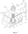
- a plurality of studs 100 extend from the heat shields 72, 74 to mount the heat shields 72, 74 to the respective support shells 68, 70 with a respective nut 102 (shown in Figure 5 ). That is, the studs 100 project rigidly from the heat shields 72, 74 and through the respective support shells 68, 70 to receive the nut 102 at a threaded distal end section 101 thereof.
- a plurality of impingement cooling holes 104 penetrate through the support shells 68, 70 to allow air from the respective annular plenums 76, 78 to enter cavities 106A, 106B (also shown in Figure 6 ) formed in the combustor liner assemblies 60, 62 between the respective support shells 68, 70 and heat shields 72, 74.
- the impingement cooling holes 104 are generally normal to the surface of the heat shields 72, 74.
- the air in the cavities 106A, 106B provides backside impingement cooling of the heat shields 72, 74 that is generally defined herein as heat removal via internal convection.
- a plurality of film cooling holes 108 penetrate through each of the heat shields 72, 74.
- the geometry of the film cooling holes e.g, diameter, shape, density, surface angle, incidence angle, etc., as well as the location of the holes with respect to the high temperature main flow also contributes to effusion film cooling.
- the combination of impingement cooling holes 104 and film cooling holes 108 may be referred to as an Impingement Film Floatliner assembly.
- the film cooling holes 108 allow the air to pass from the cavities 106A, 106B defined in part by a cold side 110 of the heat shields 72, 74 to a hot side 112 of the heat shields 72, 74 and thereby facilitate the formation of a film of cooling air along the hot side 112.
- the film cooling holes 108 are generally more numerous than the impingement cooling holes 104 to promote the development of a film cooling along the hot side 112 to sheath the heat shields 72, 74.
- Film cooling as defined herein is the introduction of a relatively cooler airflow at one or more discrete locations along a surface exposed to a high temperature environment to protect that surface in the immediate region of the airflow injection as well as downstream thereof.
- a plurality of dilution holes 116 penetrate through both the respective support shells 68, 70 and heat shields 72, 74.
- the dilution holes 116 are located downstream of the forward assembly 80 to quench the hot gases by supplying cooling air into the combustor.
- the hot combustion gases slow towards the dilution holes 116 and may form a stagnation point at the leading edge which becomes a heat source and may challenge the durability of the heat shields 72, 74 proximate this location.
- hot gases form a standing vortex pair that may also challenge the durability of the heat shields 72, 74 proximate this location.
- Each of the plurality of studs 100 that extend from the heat shields 72, 74 are surrounded by a plurality of standoff pins 120.
- the plurality of standoff pins 120 may be arranged to support the nut102 when threaded to the stud 100. That is, the standoff pins 120 prevent undesirable deflection of the support shells 68, 70 once the fasteners102 is threaded onto the stud 100.
- the plurality of standoff pins 120 may be arranged in a ring pattern 122 of a diameter about equal to the diameter of the nut 102.
- the heat shields 72, 74, their associated attachment studs 100, and film cooling holes 108 may be manufactured via an additive manufacturing process.
- the additive manufacturing process includes, but are not limited to, Selective Laser Sintering (SLS), Electron Beam Sintering (EBS), Electron Beam Melting (EBM), Electron Beam Powder Bed Fusion (EB-PBF), Electron Beam Powder Wire (EBW), Laser Engineered Net Shaping (LENS), Laser Net Shape Manufacturing (LNSM), Direct Metal Deposition (DMD), and Laser Powder Bed Fusion (L-PBF).
- SLS Selective Laser Sintering
- EBS Electron Beam Sintering
- EBM Electron Beam Melting
- EB-PBF Electron Beam Powder Bed Fusion
- EBW Electron Beam Powder Wire
- LENS Laser Engineered Net Shaping
- LNSM Laser Net Shape Manufacturing
- DMD Direct Metal Deposition
- L-PBF Laser Powder Bed Fusion
- the additive manufacturing process sequentially builds-up layers of atomized alloy and/or ceramic powder material that include, but is not limited to, 625 Alloy, 718 Alloy, 230 Alloy, stainless steel, tool steel, cobalt chrome, titanium, nickel, aluminum. silicon carbide, silicon nitride, and others in atomized powder material form. Alloys such as 625, 718 and 230 may have specific benefit for components that operate in high temperature environments, such as, for example, environments typically encountered by aerospace and gas turbine engine components. Although particular additive manufacturing processes are disclosed, it should be appreciated that any other suitable rapid manufacturing methods using layer-by-layer construction or additive fabrication can alternatively be used.
- the additive manufacturing process facilitates manufacture of the numerous and relatively complex arrangement of film cooling holes 108 in the heat shields 72, 74.
- the additive manufacturing process fabricates, or "grows," of components using three-dimensional information, for example a three-dimensional computer model.
- the three-dimensional information is converted into a plurality of slices, each slice defining a cross section of the component for a predetermined height of the slice.
- the additive manufactured component is then "grown" slice by slice, or layer by layer, until finished.
- Each layer may have an example size between about 0.0005 - 0.001 inches (0.0127 - 0.0254 mm).
- the heat shields 72, 74 and the relatively complex arrangement of film cooling holes 108 permits the extension of the cooling scheme to be adjacent the attachment stud 100 and the standoff pins 120 in a manner otherwise unobtainable with laser drilling.
- the film cooling holes 108A are located within the ring pattern 122 of standoff pins 120 ( Figure 7 ). It should be appreciated that the ring pattern 122 is merely representative of an arrangement of standoff pins 120, and other arrangements will also benefit herefrom
- the film cooling holes 108A may alternatively, or additionally, be located near the standoff pins 120, between the standoff pins 120, and/or between the standoff pins 120 and the attachment stud 100.
- the film cooling holes 108A adjacent to the attachment stud 100 can be aligned with the surrounding film cooling holes 108 to provide a uniform film that is contiguous. It should be appreciated that these film cooling holes 108A can be additive manufactured at various angles, patterns, sizes, or shapes to counter local flow conditions adjacent to each attachment stud 100.
- Additive manufacturing of the heat shields 72, 74 readily permits the addition of film cooling holes 108A proximate the attachment stud 100, readily distributes uniform film cooling air adjacent to this mechanical support structure which has heretofore been a hot spot area. Additive manufacturing also permits the placement of the film cooling holes 108A without risk of back strikes into the mechanical support structure
- the additive manufacturing of the heat shields 72, 74 readily permits the attachment stud 100 to be manufactured with an at least partially hollow stud section.
- the at least partially hollow attachment stud 100 defines a cooling air passage 130 along an axis S of the attachment stud 100 ( Figure 9 ).
- the cooling air passage 130 may terminate at the cold side 110 of the heat shields 72, 74 with the plurality of stud cooling holes 132 that extend transverse to the axis S to communicate cooling air into the respective cavities 106A, 106B and thereby compensate for a lack of impingement cooling at that location. That is, the stud cooling passages are axially located between the respective heat shield 72, 74 and the support shell 68, 70.
- the plurality of stud cooling holes 132 may be located adjacent to a stud end 140 of the attachment stud 100. That is, the stud end 140 essentially forms a bottom of the attachment stud 100 and may be essentially flush with the cold side 110 of the heat shields 72, 74.
- the plurality of cooling holes 132 may be of various angles, patterns, sizes, or shapes to counter local flow conditions adjacent to each attachment stud 100 that is simply unobtainable with laser drilling.
- the plurality of stud cooling holes 132 are arranged in a radial spoke pattern ( Figure 10 ).
- the plurality of stud cooling holes 132 is arranged in a spiral pattern ( Figure 11 ). It should be appreciated that each of the plurality of stud cooling holes 132 may be of individually different angles, patterns, sizes, and/or shapes.
- the radial or spiral cooling holes near the hot end of the cavity facilitate the provision of backside cooling.
- a plurality of film cooling holes 108B may be located through the stud end 140 of the attachment stud 100.
- the film cooling holes 108B can be arranged to align film cooling from the a stud end 140 with the surrounding film cooling holes 108 to produce a uniform film cooling that removes the heretofore dearth of film cooling adjacent to the attachment location caused by the mechanical support structure.
- the film cooling holes 108B can have different angles, sizes, or shapes, in comparison to the film cooling holes 108 to control the volume and direction of film cooling.
- Additive manufacturing permits the entirety of the heat shields 72, 74, including the attachment locations, to receive uniform film cooling air. If a hot spot occurs at an attachment location, cooling air directed thereto can improve the life of the panel, and thus reduce maintenance and replacement costs. Also, as laser drilling is avoided, the potential risk of liberated slivers damaging downstream hardware is completely avoided.
Abstract
Description
- The present disclosure relates to a gas turbine engine and, more particularly, to a combustor section therefor.
- Gas turbine engines, such as those that power modern commercial and military aircraft, generally include a compressor section to pressurize an airflow, a combustor section for burning a hydrocarbon fuel in the presence of the pressurized air, and a turbine section to extract energy from the resultant combustion gases.
- Combustors are subject to high thermal loads for prolonged time periods. Historically, combustors have implemented various cooling arrangements to cool the combustor liner assemblies. Among these is a double liner assembly that locates heat shields directly adjacent to the combustion gases. The heat shields are cooled via impingement on the backside and film cooling on the combustion gas side to maintain temperatures within material limits.
- The film cooling is typically effectuated with numerous laser-drilled film cooling holes through the heat shields. Although effective, the film cooling holes cannot be located near mechanical support structure such as the attachment studs and surrounding standoff pins as the laser drilling can back strike the mechanical support structure. Such a back strike may weaken the mechanical support structure.
- Typically, a localized hot spot occurs adjacent to the mechanical support structure due the lack of film cooling holes. Such a hot spot may eventually result in oxidation and reduced durability proximate the mechanical support structure
- A heat shield for use in a combustor of a gas turbine engine according to one disclosed non-limiting embodiment of the present disclosure can include a plurality of standoff pins that extend from a cold side, the plurality of standoff pins at least partially surround an attachment stud, the cold side including at least one film cooling hole adjacent to the plurality of standoff pins and the attachment stud.
- In a further embodiment of any of the embodiments of the present disclosure, the plurality of standoff pins is arranged in a ring pattern.
- In a further embodiment of any of the embodiments of the present disclosure, the at least one film cooling hole is located within a diameter defined by the ring pattern.
- In a further embodiment of any of the embodiments of the present disclosure, the at least one film cooling hole is located between the plurality of standoff pins and the attachment stud.
- In a further embodiment of any of the embodiments of the present disclosure, the at least one film cooling hole is located between two of the plurality of standoff pins.
- In a further embodiment of any of the embodiments of the present disclosure, the at least one film cooling hole is located between two of the plurality of standoff pins, the at least one film cooling hole located along a ring pattern defined by the plurality of standoff pins.
- In a further embodiment of any of the embodiments of the present disclosure, the heat shield is additively manufactured.
- A combustor for a gas turbine engine according to one disclosed non-limiting embodiment of the present disclosure can include a support shell having a plurality of impingement cooling holes and a heat shield having an attachment stud that extends from a cold side of the heat shield through a stud aperture in the support shell, the heat shield having a plurality of standoff pins that extend from the cold side to abut the support shell and at least partially surround the attachment stud, the cold side including at least one film cooling hole adjacent to the plurality of standoff pins and the attachment stud.
- A further embodiment of any of the embodiments of the present disclosure may include a nut received onto the attachment strut to retain the heat shield to the support shell.
- In a further embodiment of any of the embodiments of the present disclosure, the plurality of standoff pins is arranged in a ring pattern.
- In a further embodiment of any of the embodiments of the present disclosure, the ring pattern defines a diameter less than a diameter of the nut.
- In a further embodiment of any of the embodiments of the present disclosure, the at least one film cooling hole is located within a diameter defined by the ring pattern.
- In a further embodiment of any of the embodiments of the present disclosure, the at least one film cooling hole is located between the plurality of standoff pins and the attachment stud.
- In a further embodiment of any of the embodiments of the present disclosure, the at least one film cooling hole is located between two of the plurality of standoff pins.
- In a further embodiment of any of the embodiments of the present disclosure, the at least one film cooling hole is located between two of the plurality of standoff pins, the at least one film cooling hole located along the ring pattern defined by the plurality of standoff pins.
- In a further embodiment of any of the embodiments of the present disclosure may, the heat shield is additively manufactured.
- A method of manufacturing a heat shield of a combustor for a gas turbine engine according to one disclosed non-limiting embodiment of the present disclosure can include additively manufacturing an attachment stud and a plurality of standoff pins that extend from a cold side of the heat shield; the additively manufacturing a plurality of film cooling holes through the heat shield, at least one of the plurality of film cooling holes adjacent to the plurality of standoff pins and the attachment stud.
- A further embodiment of any of the embodiments of the present disclosure may include additively manufacturing the plurality of standoff pins to be arranged in a ring pattern, the at least one of the plurality of film cooling holes located within a diameter defined by the ring pattern.
- A further embodiment of any of the embodiments of the present disclosure may include additively manufacturing the plurality of standoff pins in the ring pattern along a diameter less than a diameter of a nut receivable onto the attachment stud.
- The foregoing features and elements may be combined in various combinations without exclusivity, unless expressly indicated otherwise. These features and elements as well as the operation thereof will become more apparent in light of the following description and the accompanying drawings. It should be appreciated, however, the following description and drawings are intended to be exemplary in nature and non-limiting.
- Various features will become apparent to those skilled in the art from the following detailed description of the disclosed non-limiting embodiment. The drawings that accompany the detailed description can be briefly described as follows:
-
Figure 1 is a schematic cross-section of a gas turbine engine; -
Figure 2 is an expanded longitudinal schematic sectional view of a combustor section according to one non-limiting embodiment that may be used with the gas turbine engine shown inFigure 1 ; -
Figure 3 is an expanded longitudinal schematic partial perspective view of a combustor section according to one non-limiting embodiment that may be used with the gas turbine engine shown inFigure 1 ; -
Figure 4 is an expanded perspective view of a heat shield array from a cold side; -
Figure 5 is an exploded view of a liner assembly illustrating one attachment stud thereof; -
Figure 6 is an expanded sectional view of the attachment stud ofFigure 5 ; -
Figure 7 is a top view of a heat shield with film cooling holes according to one non-limiting embodiment; -
Figure 8 is an exploded view of a liner assembly illustrating one hollow attachment stud according to another non-limiting embodiment; -
Figure 9 is an expanded sectional view of the attachment stud ofFigure 8 ; -
Figure 10 is an expanded lateral sectional view of a hollow attachment stud according to another non-limiting embodiment; and -
Figure 11 is an expanded lateral sectional view of a hollow attachment stud according to another non-limiting embodiment. -
Figure 1 schematically illustrates agas turbine engine 20. Thegas turbine engine 20 is disclosed herein as a two-spool turbo fan that generally incorporates afan section 22, acompressor section 24, acombustor section 26 and aturbine section 28. Alternative engines might include an augmentor section (not shown) among other systems or features. Thefan section 22 drives air along a bypass flowpath while thecompressor section 24 drives air along a core flowpath for compression and communication into thecombustor section 26 then expansion through theturbine section 28. Although depicted as a turbofan in the disclosed non-limiting embodiment, it should be appreciated that the concepts described herein are not limited to use only with turbofans as the teachings may be applied to other types of turbine engines such as a turbojets, turboshafts, and three-spool (plus fan) turbofans. - The
engine 20 generally includes alow spool 30 and ahigh spool 32 mounted for rotation about an engine central longitudinal axis A relative to an enginestatic structure 36 viaseveral bearing structures 38. Thelow spool 30 generally includes aninner shaft 40 that interconnects afan 42, a low pressure compressor ("LPC") 44 and a low pressure turbine ("LPT") 46. Theinner shaft 40 drives thefan 42 directly or through a gearedarchitecture 48 to drive thefan 42 at a lower speed than thelow spool 30. An exemplary reduction transmission is an epicyclic transmission, namely a planetary or star gear system. - The
high spool 32 includes anouter shaft 50 that interconnects a high pressure compressor ("HPC") 52 and high pressure turbine ("HPT") 54. Acombustor 56 is arranged between the HPC 52 and the HPT 54. Theinner shaft 40 and theouter shaft 50 are concentric and rotate about the engine central longitudinal axis A which is collinear with their longitudinal axes. - Core airflow is compressed by the
LPC 44 then the HPC 52, mixed with the fuel and burned in thecombustor 56, then expanded over the HPT 54 and theLPT 46. The the HPT 54 and theLPT 46 rotationally drive the respectivehigh spool 32 andlow spool 30 in response to the expansion. Themain engine shafts structures 38 within thestatic structure 36. It should be appreciated that various bearingstructures 38 at various locations may alternatively or additionally be provided. - In one non-limiting example, the
gas turbine engine 20 is a high-bypass geared aircraft engine. In a further example, thegas turbine engine 20 bypass ratio is greater than about six (6:1). The gearedarchitecture 48 can include an epicyclic gear train, such as a planetary gear system or other gear system. The example epicyclic gear train has a gear reduction ratio of greater than about 2.3:1, and in another example is greater than about 2.5:1. The geared turbofan enables operation of thelow spool 30 at higher speeds which can increase the operational efficiency of theLPC 44 andLPT 46 and render increased pressure in a fewer number of stages. - A pressure ratio associated with the
LPT 46 is pressure measured prior to the inlet of theLPT 46 as related to the pressure at the outlet of theLPT 46 prior to an exhaust nozzle of thegas turbine engine 20. In one non-limiting embodiment, the bypass ratio of thegas turbine engine 20 is greater than about ten (10:1), the fan diameter is significantly larger than that of theLPC 44, and theLPT 46 has a pressure ratio that is greater than about five (5:1). It should be appreciated, however, that the above parameters are only exemplary of one embodiment of a geared architecture engine and that the present disclosure is applicable to other gas turbine engines including direct drive turbofans. - In one embodiment, a significant amount of thrust is provided by the bypass flow path due to the high bypass ratio. The
fan section 22 of thegas turbine engine 20 is designed for a particular flight condition - typically cruise at about 0.8 Mach and about 35,000 feet (10,668 m). This flight condition, with thegas turbine engine 20 at its best fuel consumption, is also known as bucket cruise Thrust Specific Fuel Consumption (TSFC). TSFC is an industry standard parameter of fuel consumption per unit of thrust. - Fan Pressure Ratio is the pressure ratio across a blade of the
fan section 22 without the use of a Fan Exit Guide Vane system. The low Fan Pressure Ratio according to one non-limiting embodiment of the examplegas turbine engine 20 is less than 1.45:1. Low Corrected Fan Tip Speed is the actual fan tip speed divided by an industry standard temperature correction of ("T" / 518.7)0.5 in which "T" represents the ambient temperature in degrees Rankine (where R = K x 9/5). The Low Corrected Fan Tip Speed according to one non-limiting embodiment of the examplegas turbine engine 20 is less than about 1150 fps (351 m/s). - With reference to
Figure 2 , thecombustor 56 generally includes an outercombustor liner assembly 60, an innercombustor liner assembly 62 and adiffuser case module 64. The outercombustor liner assembly 60 and the innercombustor liner assembly 62 are spaced apart such that acombustion chamber 66 is defined therebetween. Thecombustion chamber 66 is generally annular in shape. - The outer
combustor liner assembly 60 is spaced radially inward from an outer diffuser case 64-0 of thediffuser case module 64 to define an outerannular plenum 76. The innercombustor liner assembly 62 is spaced radially outward from an inner diffuser case 64-I of thediffuser case module 64 to define an innerannular plenum 78. It should be appreciated that although a particular combustor is illustrated, other combustor types with various combustor liner arrangements will also benefit herefrom. It should be further appreciated that the disclosed cooling flow paths are but an illustrated embodiment and should not be limited only thereto. - The
combustor liner assemblies turbine section 28. Eachcombustor liner assembly respective support shell respective support shell forward heat shields 72A and a plurality ofaft heat shields 72B that are circumferentially staggered to line the hot side of the support shell 68 (also shown inFigure 3 ). A plurality offorward heat shields 74A and a plurality ofaft heat shields 74B are circumferentially staggered to line the hot side of the inner shell 70 (also shown inFigure 3 ). - The
combustor 56 further includes aforward assembly 80 immediately downstream of thecompressor section 24 to receive compressed airflow therefrom. Theforward assembly 80 generally includes anannular hood 82, abulkhead assembly 84, a plurality of fuel nozzles 86 (one shown) and a plurality of fuel nozzle guides 90 (one shown). Each of the fuel nozzle guides 90 is circumferentially aligned with one of thehood ports 94 to project through thebulkhead assembly 84. Eachbulkhead assembly 84 includes abulkhead support shell 96 secured to thecombustor liner assemblies bulkhead heat shields 98 secured to thebulkhead support shell 96 around thecentral opening 92. - The
annular hood 82 extends radially between, and is secured to, the forwardmost ends of thecombustor liner assemblies annular hood 82 includes a plurality of circumferentially distributedhood ports 94 that accommodate therespective fuel nozzle 86 and introduce air into the forward end of thecombustion chamber 66 through acentral opening 92. Eachfuel nozzle 86 may be secured to thediffuser case module 64 and project through one of thehood ports 94 and through thecentral opening 92 within the respectivefuel nozzle guide 90. - The
forward assembly 80 introduces core combustion air into the forward section of thecombustion chamber 66 while the remainder enters the outerannular plenum 76 and the innerannular plenum 78. The plurality offuel nozzles 86 and adjacent structure generate a blended fuel-air mixture that supports stable combustion in thecombustion chamber 66. - Opposite the
forward assembly 80, the outer andinner support shells HPT 54. TheNGVs 54A are static engine components which direct core airflow combustion gases onto the turbine blades of the first turbine rotor in theturbine section 28 to facilitate the conversion of pressure energy into kinetic energy. The core airflow combustion gases are also accelerated by theNGVs 54A because of their convergent shape and are typically given a "spin" or a "swirl" in the direction of turbine rotor rotation. The turbine rotor blades absorb this energy to drive the turbine rotor at high speed. - With reference to
Figure 4 , a plurality ofstuds 100 extend from the heat shields 72, 74 to mount the heat shields 72, 74 to therespective support shells Figure 5 ). That is, thestuds 100 project rigidly from the heat shields 72, 74 and through therespective support shells nut 102 at a threadeddistal end section 101 thereof. - With reference to
Figure 5 , a plurality of impingement cooling holes 104 penetrate through thesupport shells annular plenums cavities Figure 6 ) formed in thecombustor liner assemblies respective support shells cavities - A plurality of film cooling holes 108 penetrate through each of the heat shields 72, 74. The geometry of the film cooling holes, e.g, diameter, shape, density, surface angle, incidence angle, etc., as well as the location of the holes with respect to the high temperature main flow also contributes to effusion film cooling. The combination of impingement cooling holes 104 and film cooling holes 108 may be referred to as an Impingement Film Floatliner assembly.
- The film cooling holes 108 allow the air to pass from the
cavities cold side 110 of the heat shields 72, 74 to ahot side 112 of the heat shields 72, 74 and thereby facilitate the formation of a film of cooling air along thehot side 112. The film cooling holes 108 are generally more numerous than the impingement cooling holes 104 to promote the development of a film cooling along thehot side 112 to sheath the heat shields 72, 74. Film cooling as defined herein is the introduction of a relatively cooler airflow at one or more discrete locations along a surface exposed to a high temperature environment to protect that surface in the immediate region of the airflow injection as well as downstream thereof. - A plurality of dilution holes 116 penetrate through both the
respective support shells forward assembly 80 to quench the hot gases by supplying cooling air into the combustor. The hot combustion gases slow towards the dilution holes 116 and may form a stagnation point at the leading edge which becomes a heat source and may challenge the durability of the heat shields 72, 74 proximate this location. At the trailing edge of the dilution hole, due to interaction with dilution jet, hot gases form a standing vortex pair that may also challenge the durability of the heat shields 72, 74 proximate this location. - Each of the plurality of
studs 100 that extend from the heat shields 72, 74 are surrounded by a plurality of standoff pins 120. The plurality of standoff pins 120 may be arranged to support the nut102 when threaded to thestud 100. That is, the standoff pins 120 prevent undesirable deflection of thesupport shells stud 100. In one embodiment, the plurality of standoff pins 120 may be arranged in aring pattern 122 of a diameter about equal to the diameter of thenut 102. - The heat shields 72, 74, their associated
attachment studs 100, and film cooling holes 108 may be manufactured via an additive manufacturing process. The additive manufacturing process includes, but are not limited to, Selective Laser Sintering (SLS), Electron Beam Sintering (EBS), Electron Beam Melting (EBM), Electron Beam Powder Bed Fusion (EB-PBF), Electron Beam Powder Wire (EBW), Laser Engineered Net Shaping (LENS), Laser Net Shape Manufacturing (LNSM), Direct Metal Deposition (DMD), and Laser Powder Bed Fusion (L-PBF). - The additive manufacturing process sequentially builds-up layers of atomized alloy and/or ceramic powder material that include, but is not limited to, 625 Alloy, 718 Alloy, 230 Alloy, stainless steel, tool steel, cobalt chrome, titanium, nickel, aluminum. silicon carbide, silicon nitride, and others in atomized powder material form. Alloys such as 625, 718 and 230 may have specific benefit for components that operate in high temperature environments, such as, for example, environments typically encountered by aerospace and gas turbine engine components. Although particular additive manufacturing processes are disclosed, it should be appreciated that any other suitable rapid manufacturing methods using layer-by-layer construction or additive fabrication can alternatively be used.
- The additive manufacturing process facilitates manufacture of the numerous and relatively complex arrangement of film cooling holes 108 in the heat shields 72, 74. The additive manufacturing process fabricates, or "grows," of components using three-dimensional information, for example a three-dimensional computer model. The three-dimensional information is converted into a plurality of slices, each slice defining a cross section of the component for a predetermined height of the slice. The additive manufactured component is then "grown" slice by slice, or layer by layer, until finished. Each layer may have an example size between about 0.0005 - 0.001 inches (0.0127 - 0.0254 mm). Although particular additive manufacturing processes are disclosed, it should be appreciated that any other suitable rapid manufacturing methods using layer-by-layer construction or additive fabrication can alternatively be used.
- Additive manufacturing the heat shields 72, 74 and the relatively complex arrangement of film cooling holes 108 permits the extension of the cooling scheme to be adjacent the
attachment stud 100 and the standoff pins 120 in a manner otherwise unobtainable with laser drilling. In one example, thefilm cooling holes 108A are located within thering pattern 122 of standoff pins 120 (Figure 7 ). It should be appreciated that thering pattern 122 is merely representative of an arrangement of standoff pins 120, and other arrangements will also benefit herefrom - The
film cooling holes 108A may alternatively, or additionally, be located near the standoff pins 120, between the standoff pins 120, and/or between the standoff pins 120 and theattachment stud 100. In one example, thefilm cooling holes 108A adjacent to theattachment stud 100 can be aligned with the surrounding film cooling holes 108 to provide a uniform film that is contiguous. It should be appreciated that thesefilm cooling holes 108A can be additive manufactured at various angles, patterns, sizes, or shapes to counter local flow conditions adjacent to eachattachment stud 100. - Additive manufacturing of the heat shields 72, 74 readily permits the addition of film cooling holes 108A proximate the
attachment stud 100, readily distributes uniform film cooling air adjacent to this mechanical support structure which has heretofore been a hot spot area. Additive manufacturing also permits the placement of thefilm cooling holes 108A without risk of back strikes into the mechanical support structure - With reference to
Figure 8 , in another disclosed non-limiting embodiment, the additive manufacturing of the heat shields 72, 74 readily permits theattachment stud 100 to be manufactured with an at least partially hollow stud section. The at least partiallyhollow attachment stud 100 defines a coolingair passage 130 along an axis S of the attachment stud 100 (Figure 9 ). - With reference to
Figure 9 , the coolingair passage 130 may terminate at thecold side 110 of the heat shields 72, 74 with the plurality of stud cooling holes 132 that extend transverse to the axis S to communicate cooling air into therespective cavities support shell - The plurality of stud cooling holes 132 may be located adjacent to a stud end 140 of the
attachment stud 100. That is, the stud end 140 essentially forms a bottom of theattachment stud 100 and may be essentially flush with thecold side 110 of the heat shields 72, 74. The plurality ofcooling holes 132 may be of various angles, patterns, sizes, or shapes to counter local flow conditions adjacent to eachattachment stud 100 that is simply unobtainable with laser drilling. In one example, the plurality of stud cooling holes 132 are arranged in a radial spoke pattern (Figure 10 ). In another example, the plurality of stud cooling holes 132 is arranged in a spiral pattern (Figure 11 ). It should be appreciated that each of the plurality of stud cooling holes 132 may be of individually different angles, patterns, sizes, and/or shapes. The radial or spiral cooling holes near the hot end of the cavity facilitate the provision of backside cooling. - In another embodiment, a plurality of film cooling holes 108B may be located through the stud end 140 of the
attachment stud 100. The film cooling holes 108B can be arranged to align film cooling from the a stud end 140 with the surrounding film cooling holes 108 to produce a uniform film cooling that removes the heretofore dearth of film cooling adjacent to the attachment location caused by the mechanical support structure. It should be appreciated that the film cooling holes 108B can have different angles, sizes, or shapes, in comparison to the film cooling holes 108 to control the volume and direction of film cooling. - Additive manufacturing permits the entirety of the heat shields 72, 74, including the attachment locations, to receive uniform film cooling air. If a hot spot occurs at an attachment location, cooling air directed thereto can improve the life of the panel, and thus reduce maintenance and replacement costs. Also, as laser drilling is avoided, the potential risk of liberated slivers damaging downstream hardware is completely avoided.
- The use of the terms "a," "an," "the," and similar references in the context of description (especially in the context of the following claims) are to be construed to cover both the singular and the plural, unless otherwise indicated herein or specifically contradicted by context. The modifier "about" used in connection with a quantity is inclusive of the stated value and has the meaning dictated by the context (e.g., it includes the degree of error associated with measurement of the particular quantity). All ranges disclosed herein are inclusive of the endpoints, and the endpoints are independently combinable with each other. It should be appreciated that relative positional terms such as "forward," "aft," "upper," "lower," "above," "below," and the like are with reference to the normal operational attitude of the vehicle and should not be considered otherwise limiting.
- Although the different non-limiting embodiments have specific illustrated components, the embodiments of this invention are not limited to those particular combinations. It is possible to use some of the components or features from any of the non-limiting embodiments in combination with features or components from any of the other non-limiting embodiments.
- It should be appreciated that like reference numerals identify corresponding or similar elements throughout the several drawings. It should also be appreciated that although a particular component arrangement is disclosed in the illustrated embodiment, other arrangements will benefit herefrom.
- Although particular step sequences are shown, described, and claimed, it should be appreciated that steps may be performed in any order, separated or combined unless otherwise indicated and will still benefit from the present disclosure.
- The foregoing description is exemplary rather than defined by the limitations within. Various non-limiting embodiments are disclosed herein, however, one of ordinary skill in the art would recognize that various modifications and variations in light of the above teachings will fall within the scope of the appended claims. It is therefore to be appreciated that within the scope of the appended claims, the disclosure may be practiced other than as specifically described. For that reason the appended claims should be studied to determine true scope and content.
Claims (13)
- A heat shield (72, 74) for use in a combustor (26) of a gas turbine engine (20) comprising:a plurality of standoff pins (120) that extend from a cold side (110), said plurality of standoff pins (120) at least partially surround an attachment stud (100), said cold side (110) including at least one film cooling hole (108) adjacent to said plurality of standoff pins (120) and said attachment stud (100).
- The heat shield (72, 74) as recited in claim 1, wherein said plurality of standoff pins (120) is arranged in a ring pattern (122).
- The heat shield (72, 74) as recited in claim 2, wherein said at least one film cooling hole (108) is located within a diameter defined by said ring pattern (122).
- The heat shield (72, 74) as recited in claim 1, 2 or 3, wherein said at least one film cooling hole (108) is located between said plurality of standoff pins (120) and said attachment stud (100).
- The heat shield (72, 74) as recited in claim 1 or 2, wherein said at least one film cooling hole (108) is located between two of said plurality of standoff pins (120).
- The heat shield (72, 74) as recited in claim 2, wherein said at least one film cooling hole (108) is located between two of said plurality of standoff pins (120), said at least one film cooling hole (108) located along said ring pattern (122).
- The heat shield (72, 74) as recited in any preceding claim, wherein said heat shield (72, 74) is additively manufactured.
- A combustor (26) for a gas turbine engine (20) comprising:a support shell (68, 70) having a plurality of impingement cooling holes (104); andthe heat shield (72, 74) of any preceding claim wherein the attachment stud (100) extends from a cold side (110) of said heat shield (72, 74) through a stud aperture in said support shell (68, 70), and wherein said plurality of standoff pins (120) extend from said cold side (110) to abut said support shell (68, 70).
- The combustor (26) as recited in claim 8, further comprising a nut (102) received onto said attachment stud (100) to retain said heat shield (72, 74) to said support shell (68, 70).
- The combustor (26) as recited in claim 8 or 9 as dependent directly or indirectly upon claim 2, wherein said ring pattern (122) defines a diameter less than a diameter of said nut (102).
- A method of manufacturing a heat shield (72, 74) of a combustor for a gas turbine engine, comprising:additively manufacturing an attachment stud (100) and a plurality of standoff pins (120) that extend from a cold side (110) of said heat shield (72, 74); andadditively manufacturing a plurality of film cooling holes (108) through said heat shield (72, 74), at least one of said plurality of film cooling holes (108) adjacent to said plurality of standoff pins (120) and said attachment stud (100).
- The method as recited in claim 11, further comprising:additively manufacturing said plurality of standoff pins (120) to be arranged in a ring pattern (122), said at least one of said plurality of film cooling holes (108) located within a diameter defined by said ring pattern (122).
- The method as recited in claim 12, further comprising:additively manufacturing said plurality of standoff pins (120) in said ring pattern (122) along a diameter less than a diameter of a nut (102) receivable onto said attachment stud (100).
Applications Claiming Priority (1)
| Application Number | Priority Date | Filing Date | Title |
|---|---|---|---|
| US14/694,086 US10935240B2 (en) | 2015-04-23 | 2015-04-23 | Additive manufactured combustor heat shield |
Publications (2)
| Publication Number | Publication Date |
|---|---|
| EP3086041A1 true EP3086041A1 (en) | 2016-10-26 |
| EP3086041B1 EP3086041B1 (en) | 2021-07-07 |
Family
ID=55806245
Family Applications (1)
| Application Number | Title | Priority Date | Filing Date |
|---|---|---|---|
| EP16166599.7A Active EP3086041B1 (en) | 2015-04-23 | 2016-04-22 | Additive manufactured combustor heat shield |
Country Status (2)
| Country | Link |
|---|---|
| US (1) | US10935240B2 (en) |
| EP (1) | EP3086041B1 (en) |
Cited By (6)
| Publication number | Priority date | Publication date | Assignee | Title |
|---|---|---|---|---|
| EP3453967A1 (en) * | 2017-09-08 | 2019-03-13 | United Technologies Corporation | Cooling configurations for combustor attachment features |
| EP3502565A1 (en) * | 2017-12-22 | 2019-06-26 | United Technologies Corporation | Apparatus for mitigating particulate accumulation on a component of a gas turbine |
| US10619857B2 (en) | 2017-09-08 | 2020-04-14 | United Technologies Corporation | Cooling configuration for combustor attachment feature |
| US10670275B2 (en) | 2017-09-08 | 2020-06-02 | Raytheon Technologies Corporation | Cooling configurations for combustor attachment features |
| US10670274B2 (en) | 2017-09-08 | 2020-06-02 | Raytheon Technologies Corporation | Cooling configurations for combustor attachment features |
| EP3800328A1 (en) * | 2019-10-04 | 2021-04-07 | Raytheon Technologies Corporation | Engine turbine support structure |
Families Citing this family (5)
| Publication number | Priority date | Publication date | Assignee | Title |
|---|---|---|---|---|
| US11112117B2 (en) | 2018-07-17 | 2021-09-07 | General Electric Company | Fuel nozzle cooling structure |
| US11402096B2 (en) | 2018-11-05 | 2022-08-02 | Rolls-Royce Corporation | Combustor dome via additive layer manufacturing |
| US11402100B2 (en) * | 2018-11-15 | 2022-08-02 | Pratt & Whitney Canada Corp. | Ring assembly for double-skin combustor liner |
| US11561007B2 (en) * | 2019-01-04 | 2023-01-24 | United Technologies Corporation | Combustor cooling panel stud |
| CN116928697A (en) | 2022-04-06 | 2023-10-24 | 通用电气公司 | Burner deflector assembly |
Citations (4)
| Publication number | Priority date | Publication date | Assignee | Title |
|---|---|---|---|---|
| US20030213250A1 (en) * | 2002-05-16 | 2003-11-20 | Monica Pacheco-Tougas | Heat shield panels for use in a combustor for a gas turbine engine |
| US20140216042A1 (en) * | 2012-09-28 | 2014-08-07 | United Technologies Corporation | Combustor component with cooling holes formed by additive manufacturing |
| WO2014200588A2 (en) * | 2013-03-14 | 2014-12-18 | United Technologies Corporation | Additive manufactured gas turbine engine combustor liner panel |
| WO2015047472A2 (en) * | 2013-06-14 | 2015-04-02 | United Technologies Corporation | Conductive panel surface cooling augmentation for gas turbine engine combustor |
Family Cites Families (26)
| Publication number | Priority date | Publication date | Assignee | Title |
|---|---|---|---|---|
| US4191011A (en) | 1977-12-21 | 1980-03-04 | General Motors Corporation | Mount assembly for porous transition panel at annular combustor outlet |
| US4195476A (en) | 1978-04-27 | 1980-04-01 | General Motors Corporation | Combustor construction |
| US4422300A (en) * | 1981-12-14 | 1983-12-27 | United Technologies Corporation | Prestressed combustor liner for gas turbine engine |
| US5144793A (en) * | 1990-12-24 | 1992-09-08 | United Technologies Corporation | Integrated connector/airtube for a turbomachine's combustion chamber walls |
| US5323601A (en) | 1992-12-21 | 1994-06-28 | United Technologies Corporation | Individually removable combustor liner panel for a gas turbine engine |
| GB2295887A (en) | 1994-12-08 | 1996-06-12 | Rolls Royce Plc | Combustor assembly |
| GB2298267B (en) | 1995-02-23 | 1999-01-13 | Rolls Royce Plc | An arrangement of heat resistant tiles for a gas turbine engine combustor |
| US5758503A (en) | 1995-05-03 | 1998-06-02 | United Technologies Corporation | Gas turbine combustor |
| GB2306155B (en) | 1995-10-11 | 1997-11-19 | Toshiba Kk | Apparatus and method for disassembling and assembling gas turbine combuster |
| GB2380236B (en) * | 2001-09-29 | 2005-01-19 | Rolls Royce Plc | A wall structure for a combustion chamber of a gas turbine engine |
| US7013647B2 (en) | 2001-12-21 | 2006-03-21 | Mitsubishi Heavy Industries, Ltd. | Outer casing covering gas turbine combustor |
| EP1389690B1 (en) * | 2002-08-16 | 2007-01-03 | Siemens Aktiengesellschaft | Screw interiorly cooled |
| US7024863B2 (en) | 2003-07-08 | 2006-04-11 | Pratt & Whitney Canada Corp. | Combustor attachment with rotational joint |
| US7146815B2 (en) * | 2003-07-31 | 2006-12-12 | United Technologies Corporation | Combustor |
| US7631503B2 (en) | 2006-09-12 | 2009-12-15 | Pratt & Whitney Canada Corp. | Combustor with enhanced cooling access |
| US7827800B2 (en) | 2006-10-19 | 2010-11-09 | Pratt & Whitney Canada Corp. | Combustor heat shield |
| US20100095679A1 (en) * | 2008-10-22 | 2010-04-22 | Honeywell International Inc. | Dual wall structure for use in a combustor of a gas turbine engine |
| US8495881B2 (en) | 2009-06-02 | 2013-07-30 | General Electric Company | System and method for thermal control in a cap of a gas turbine combustor |
| US8800298B2 (en) * | 2009-07-17 | 2014-08-12 | United Technologies Corporation | Washer with cooling passage for a turbine engine combustor |
| GB0913580D0 (en) | 2009-08-05 | 2009-09-16 | Rolls Royce Plc | Combustor tile |
| US8739546B2 (en) * | 2009-08-31 | 2014-06-03 | United Technologies Corporation | Gas turbine combustor with quench wake control |
| US9416970B2 (en) * | 2009-11-30 | 2016-08-16 | United Technologies Corporation | Combustor heat panel arrangement having holes offset from seams of a radially opposing heat panel |
| US8910378B2 (en) | 2012-05-01 | 2014-12-16 | United Technologies Corporation | Method for working of combustor float wall panels |
| US20140093370A1 (en) * | 2012-09-28 | 2014-04-03 | United Technologies Corporation | Gas turbine engine combustor liner |
| GB201222311D0 (en) * | 2012-12-12 | 2013-01-23 | Rolls Royce Plc | A combusiton chamber |
| US8984896B2 (en) | 2013-08-23 | 2015-03-24 | Pratt & Whitney Canada Corp. | Interlocking combustor heat shield panels |
-
2015
- 2015-04-23 US US14/694,086 patent/US10935240B2/en active Active
-
2016
- 2016-04-22 EP EP16166599.7A patent/EP3086041B1/en active Active
Patent Citations (4)
| Publication number | Priority date | Publication date | Assignee | Title |
|---|---|---|---|---|
| US20030213250A1 (en) * | 2002-05-16 | 2003-11-20 | Monica Pacheco-Tougas | Heat shield panels for use in a combustor for a gas turbine engine |
| US20140216042A1 (en) * | 2012-09-28 | 2014-08-07 | United Technologies Corporation | Combustor component with cooling holes formed by additive manufacturing |
| WO2014200588A2 (en) * | 2013-03-14 | 2014-12-18 | United Technologies Corporation | Additive manufactured gas turbine engine combustor liner panel |
| WO2015047472A2 (en) * | 2013-06-14 | 2015-04-02 | United Technologies Corporation | Conductive panel surface cooling augmentation for gas turbine engine combustor |
Cited By (11)
| Publication number | Priority date | Publication date | Assignee | Title |
|---|---|---|---|---|
| EP3453967A1 (en) * | 2017-09-08 | 2019-03-13 | United Technologies Corporation | Cooling configurations for combustor attachment features |
| US10619857B2 (en) | 2017-09-08 | 2020-04-14 | United Technologies Corporation | Cooling configuration for combustor attachment feature |
| US10670273B2 (en) | 2017-09-08 | 2020-06-02 | Raytheon Technologies Corporation | Cooling configurations for combustor attachment features |
| US10670275B2 (en) | 2017-09-08 | 2020-06-02 | Raytheon Technologies Corporation | Cooling configurations for combustor attachment features |
| US10670274B2 (en) | 2017-09-08 | 2020-06-02 | Raytheon Technologies Corporation | Cooling configurations for combustor attachment features |
| EP4235032A3 (en) * | 2017-09-08 | 2023-10-11 | Raytheon Technologies Corporation | Combustor panel with cooling configuration for combustor panel attachment feature |
| EP3502565A1 (en) * | 2017-12-22 | 2019-06-26 | United Technologies Corporation | Apparatus for mitigating particulate accumulation on a component of a gas turbine |
| US11359810B2 (en) | 2017-12-22 | 2022-06-14 | Raytheon Technologies Corporation | Apparatus and method for mitigating particulate accumulation on a component of a gas turbine |
| EP3800328A1 (en) * | 2019-10-04 | 2021-04-07 | Raytheon Technologies Corporation | Engine turbine support structure |
| US11753952B2 (en) | 2019-10-04 | 2023-09-12 | Raytheon Technologies Corporation | Support structure for a turbine vane of a gas turbine engine |
| EP4306771A3 (en) * | 2019-10-04 | 2024-02-21 | RTX Corporation | Engine turbine support structure |
Also Published As
| Publication number | Publication date |
|---|---|
| EP3086041B1 (en) | 2021-07-07 |
| US10935240B2 (en) | 2021-03-02 |
| US20160313004A1 (en) | 2016-10-27 |
Similar Documents
| Publication | Publication Date | Title |
|---|---|---|
| EP3098513B1 (en) | Additive manufactured combustor heat shield with cooled attachment stud | |
| EP3086041B1 (en) | Additive manufactured combustor heat shield | |
| EP3366995B1 (en) | Combustor liner panel assembly and method for cooling the same | |
| US20160033129A1 (en) | Additive manufactured gas turbine engine combustor liner panel | |
| US10551066B2 (en) | Combustor liner panel and rail with diffused interface passage for a gas turbine engine combustor | |
| EP3018415B1 (en) | Combustor dilution hole cooling | |
| EP3366997B1 (en) | Combustor liner panel end rail cooling enhancement features for a gas turbine engine combustor | |
| EP3077728B1 (en) | Gas turbine engine combustor having co-swirl orientation of combustor effusion passages, and method | |
| EP3047128B1 (en) | Controlled variation of pressure drop through effusion cooling in a double walled combustor of a gas turbine engine | |
| EP3361158B1 (en) | Combustor for a gas turbine engine | |
| EP2932070B1 (en) | Gas turbine engine combustor heat shield with increased film cooling effectiveness | |
| EP3008392B1 (en) | Gas turbine engine wave geometry combustor liner panel | |
| EP2971973B1 (en) | Combustor panel and combustor with heat shield with increased durability | |
| EP2999927B1 (en) | Gas turbine engine combustor liner panel | |
| EP3315730A1 (en) | Combustor seal for a gas turbine engine combustor | |
| EP3321585B1 (en) | Non-planar combustor liner panel for a gas turbine engine combustor | |
| EP3084307B1 (en) | Dilution passage arrangement for gas turbine engine combustor | |
| EP3315862B1 (en) | Cast combustor liner panel with a radius edge for gas turbine engine combustor | |
| US10655853B2 (en) | Combustor liner panel with non-linear circumferential edge for a gas turbine engine combustor |
Legal Events
| Date | Code | Title | Description |
|---|---|---|---|
| PUAI | Public reference made under article 153(3) epc to a published international application that has entered the european phase |
Free format text: ORIGINAL CODE: 0009012 |
|
| AK | Designated contracting states |
Kind code of ref document: A1 Designated state(s): AL AT BE BG CH CY CZ DE DK EE ES FI FR GB GR HR HU IE IS IT LI LT LU LV MC MK MT NL NO PL PT RO RS SE SI SK SM TR |
|
| AX | Request for extension of the european patent |
Extension state: BA ME |
|
| RIN1 | Information on inventor provided before grant (corrected) |
Inventor name: SNYDER, BROOKE E. Inventor name: SLAVENS, THOMAS N. Inventor name: CHANG, HOYT Y. |
|
| RIN1 | Information on inventor provided before grant (corrected) |
Inventor name: SLAVENS, THOMAS N. Inventor name: SNYDER, BROOKE E. Inventor name: CHANG, HOYT Y. |
|
| STAA | Information on the status of an ep patent application or granted ep patent |
Free format text: STATUS: THE APPLICATION HAS BEEN PUBLISHED |
|
| 17P | Request for examination filed |
Effective date: 20170426 |
|
| RBV | Designated contracting states (corrected) |
Designated state(s): AL AT BE BG CH CY CZ DE DK EE ES FI FR GB GR HR HU IE IS IT LI LT LU LV MC MK MT NL NO PL PT RO RS SE SI SK SM TR |
|
| STAA | Information on the status of an ep patent application or granted ep patent |
Free format text: STATUS: REQUEST FOR EXAMINATION WAS MADE |
|
| STAA | Information on the status of an ep patent application or granted ep patent |
Free format text: STATUS: EXAMINATION IS IN PROGRESS |
|
| 17Q | First examination report despatched |
Effective date: 20200219 |
|
| GRAP | Despatch of communication of intention to grant a patent |
Free format text: ORIGINAL CODE: EPIDOSNIGR1 |
|
| STAA | Information on the status of an ep patent application or granted ep patent |
Free format text: STATUS: GRANT OF PATENT IS INTENDED |
|
| INTG | Intention to grant announced |
Effective date: 20210119 |
|
| RAP1 | Party data changed (applicant data changed or rights of an application transferred) |
Owner name: RAYTHEON TECHNOLOGIES CORPORATION |
|
| GRAS | Grant fee paid |
Free format text: ORIGINAL CODE: EPIDOSNIGR3 |
|
| GRAA | (expected) grant |
Free format text: ORIGINAL CODE: 0009210 |
|
| STAA | Information on the status of an ep patent application or granted ep patent |
Free format text: STATUS: THE PATENT HAS BEEN GRANTED |
|
| AK | Designated contracting states |
Kind code of ref document: B1 Designated state(s): AL AT BE BG CH CY CZ DE DK EE ES FI FR GB GR HR HU IE IS IT LI LT LU LV MC MK MT NL NO PL PT RO RS SE SI SK SM TR |
|
| REG | Reference to a national code |
Ref country code: GB Ref legal event code: FG4D |
|
| REG | Reference to a national code |
Ref country code: AT Ref legal event code: REF Ref document number: 1408953 Country of ref document: AT Kind code of ref document: T Effective date: 20210715 |
|
| REG | Reference to a national code |
Ref country code: DE Ref legal event code: R096 Ref document number: 602016060212 Country of ref document: DE |
|
| REG | Reference to a national code |
Ref country code: IE Ref legal event code: FG4D |
|
| REG | Reference to a national code |
Ref country code: LT Ref legal event code: MG9D |
|
| REG | Reference to a national code |
Ref country code: NL Ref legal event code: MP Effective date: 20210707 |
|
| REG | Reference to a national code |
Ref country code: AT Ref legal event code: MK05 Ref document number: 1408953 Country of ref document: AT Kind code of ref document: T Effective date: 20210707 |
|
| PG25 | Lapsed in a contracting state [announced via postgrant information from national office to epo] |
Ref country code: RS Free format text: LAPSE BECAUSE OF FAILURE TO SUBMIT A TRANSLATION OF THE DESCRIPTION OR TO PAY THE FEE WITHIN THE PRESCRIBED TIME-LIMIT Effective date: 20210707 Ref country code: SE Free format text: LAPSE BECAUSE OF FAILURE TO SUBMIT A TRANSLATION OF THE DESCRIPTION OR TO PAY THE FEE WITHIN THE PRESCRIBED TIME-LIMIT Effective date: 20210707 Ref country code: HR Free format text: LAPSE BECAUSE OF FAILURE TO SUBMIT A TRANSLATION OF THE DESCRIPTION OR TO PAY THE FEE WITHIN THE PRESCRIBED TIME-LIMIT Effective date: 20210707 Ref country code: FI Free format text: LAPSE BECAUSE OF FAILURE TO SUBMIT A TRANSLATION OF THE DESCRIPTION OR TO PAY THE FEE WITHIN THE PRESCRIBED TIME-LIMIT Effective date: 20210707 Ref country code: ES Free format text: LAPSE BECAUSE OF FAILURE TO SUBMIT A TRANSLATION OF THE DESCRIPTION OR TO PAY THE FEE WITHIN THE PRESCRIBED TIME-LIMIT Effective date: 20210707 Ref country code: PT Free format text: LAPSE BECAUSE OF FAILURE TO SUBMIT A TRANSLATION OF THE DESCRIPTION OR TO PAY THE FEE WITHIN THE PRESCRIBED TIME-LIMIT Effective date: 20211108 Ref country code: NL Free format text: LAPSE BECAUSE OF FAILURE TO SUBMIT A TRANSLATION OF THE DESCRIPTION OR TO PAY THE FEE WITHIN THE PRESCRIBED TIME-LIMIT Effective date: 20210707 Ref country code: NO Free format text: LAPSE BECAUSE OF FAILURE TO SUBMIT A TRANSLATION OF THE DESCRIPTION OR TO PAY THE FEE WITHIN THE PRESCRIBED TIME-LIMIT Effective date: 20211007 Ref country code: BG Free format text: LAPSE BECAUSE OF FAILURE TO SUBMIT A TRANSLATION OF THE DESCRIPTION OR TO PAY THE FEE WITHIN THE PRESCRIBED TIME-LIMIT Effective date: 20211007 Ref country code: AT Free format text: LAPSE BECAUSE OF FAILURE TO SUBMIT A TRANSLATION OF THE DESCRIPTION OR TO PAY THE FEE WITHIN THE PRESCRIBED TIME-LIMIT Effective date: 20210707 Ref country code: LT Free format text: LAPSE BECAUSE OF FAILURE TO SUBMIT A TRANSLATION OF THE DESCRIPTION OR TO PAY THE FEE WITHIN THE PRESCRIBED TIME-LIMIT Effective date: 20210707 |
|
| PG25 | Lapsed in a contracting state [announced via postgrant information from national office to epo] |
Ref country code: PL Free format text: LAPSE BECAUSE OF FAILURE TO SUBMIT A TRANSLATION OF THE DESCRIPTION OR TO PAY THE FEE WITHIN THE PRESCRIBED TIME-LIMIT Effective date: 20210707 Ref country code: LV Free format text: LAPSE BECAUSE OF FAILURE TO SUBMIT A TRANSLATION OF THE DESCRIPTION OR TO PAY THE FEE WITHIN THE PRESCRIBED TIME-LIMIT Effective date: 20210707 Ref country code: GR Free format text: LAPSE BECAUSE OF FAILURE TO SUBMIT A TRANSLATION OF THE DESCRIPTION OR TO PAY THE FEE WITHIN THE PRESCRIBED TIME-LIMIT Effective date: 20211008 |
|
| REG | Reference to a national code |
Ref country code: DE Ref legal event code: R097 Ref document number: 602016060212 Country of ref document: DE |
|
| PG25 | Lapsed in a contracting state [announced via postgrant information from national office to epo] |
Ref country code: DK Free format text: LAPSE BECAUSE OF FAILURE TO SUBMIT A TRANSLATION OF THE DESCRIPTION OR TO PAY THE FEE WITHIN THE PRESCRIBED TIME-LIMIT Effective date: 20210707 |
|
| PLBE | No opposition filed within time limit |
Free format text: ORIGINAL CODE: 0009261 |
|
| STAA | Information on the status of an ep patent application or granted ep patent |
Free format text: STATUS: NO OPPOSITION FILED WITHIN TIME LIMIT |
|
| PG25 | Lapsed in a contracting state [announced via postgrant information from national office to epo] |
Ref country code: SM Free format text: LAPSE BECAUSE OF FAILURE TO SUBMIT A TRANSLATION OF THE DESCRIPTION OR TO PAY THE FEE WITHIN THE PRESCRIBED TIME-LIMIT Effective date: 20210707 Ref country code: SK Free format text: LAPSE BECAUSE OF FAILURE TO SUBMIT A TRANSLATION OF THE DESCRIPTION OR TO PAY THE FEE WITHIN THE PRESCRIBED TIME-LIMIT Effective date: 20210707 Ref country code: RO Free format text: LAPSE BECAUSE OF FAILURE TO SUBMIT A TRANSLATION OF THE DESCRIPTION OR TO PAY THE FEE WITHIN THE PRESCRIBED TIME-LIMIT Effective date: 20210707 Ref country code: EE Free format text: LAPSE BECAUSE OF FAILURE TO SUBMIT A TRANSLATION OF THE DESCRIPTION OR TO PAY THE FEE WITHIN THE PRESCRIBED TIME-LIMIT Effective date: 20210707 Ref country code: CZ Free format text: LAPSE BECAUSE OF FAILURE TO SUBMIT A TRANSLATION OF THE DESCRIPTION OR TO PAY THE FEE WITHIN THE PRESCRIBED TIME-LIMIT Effective date: 20210707 Ref country code: AL Free format text: LAPSE BECAUSE OF FAILURE TO SUBMIT A TRANSLATION OF THE DESCRIPTION OR TO PAY THE FEE WITHIN THE PRESCRIBED TIME-LIMIT Effective date: 20210707 |
|
| 26N | No opposition filed |
Effective date: 20220408 |
|
| PG25 | Lapsed in a contracting state [announced via postgrant information from national office to epo] |
Ref country code: IT Free format text: LAPSE BECAUSE OF FAILURE TO SUBMIT A TRANSLATION OF THE DESCRIPTION OR TO PAY THE FEE WITHIN THE PRESCRIBED TIME-LIMIT Effective date: 20210707 |
|
| REG | Reference to a national code |
Ref country code: CH Ref legal event code: PL |
|
| REG | Reference to a national code |
Ref country code: BE Ref legal event code: MM Effective date: 20220430 |
|
| PG25 | Lapsed in a contracting state [announced via postgrant information from national office to epo] |
Ref country code: MC Free format text: LAPSE BECAUSE OF FAILURE TO SUBMIT A TRANSLATION OF THE DESCRIPTION OR TO PAY THE FEE WITHIN THE PRESCRIBED TIME-LIMIT Effective date: 20210707 Ref country code: LU Free format text: LAPSE BECAUSE OF NON-PAYMENT OF DUE FEES Effective date: 20220422 Ref country code: LI Free format text: LAPSE BECAUSE OF NON-PAYMENT OF DUE FEES Effective date: 20220430 Ref country code: CH Free format text: LAPSE BECAUSE OF NON-PAYMENT OF DUE FEES Effective date: 20220430 |
|
| PG25 | Lapsed in a contracting state [announced via postgrant information from national office to epo] |
Ref country code: BE Free format text: LAPSE BECAUSE OF NON-PAYMENT OF DUE FEES Effective date: 20220430 |
|
| PG25 | Lapsed in a contracting state [announced via postgrant information from national office to epo] |
Ref country code: IE Free format text: LAPSE BECAUSE OF NON-PAYMENT OF DUE FEES Effective date: 20220422 |
|
| PGFP | Annual fee paid to national office [announced via postgrant information from national office to epo] |
Ref country code: FR Payment date: 20230321 Year of fee payment: 8 |
|
| PGFP | Annual fee paid to national office [announced via postgrant information from national office to epo] |
Ref country code: GB Payment date: 20230321 Year of fee payment: 8 |
|
| P01 | Opt-out of the competence of the unified patent court (upc) registered |
Effective date: 20230520 |
|
| PGFP | Annual fee paid to national office [announced via postgrant information from national office to epo] |
Ref country code: DE Payment date: 20230321 Year of fee payment: 8 |
|
| PG25 | Lapsed in a contracting state [announced via postgrant information from national office to epo] |
Ref country code: HU Free format text: LAPSE BECAUSE OF FAILURE TO SUBMIT A TRANSLATION OF THE DESCRIPTION OR TO PAY THE FEE WITHIN THE PRESCRIBED TIME-LIMIT; INVALID AB INITIO Effective date: 20160422 |