EP3086037B1 - Water-cooled column and hearth having same - Google Patents
Water-cooled column and hearth having same Download PDFInfo
- Publication number
- EP3086037B1 EP3086037B1 EP14871950.3A EP14871950A EP3086037B1 EP 3086037 B1 EP3086037 B1 EP 3086037B1 EP 14871950 A EP14871950 A EP 14871950A EP 3086037 B1 EP3086037 B1 EP 3086037B1
- Authority
- EP
- European Patent Office
- Prior art keywords
- water
- sub
- cooled
- furnace
- column
- Prior art date
- Legal status (The legal status is an assumption and is not a legal conclusion. Google has not performed a legal analysis and makes no representation as to the accuracy of the status listed.)
- Active
Links
Images


Classifications
-
- F—MECHANICAL ENGINEERING; LIGHTING; HEATING; WEAPONS; BLASTING
- F22—STEAM GENERATION
- F22B—METHODS OF STEAM GENERATION; STEAM BOILERS
- F22B31/00—Modifications of boiler construction, or of tube systems, dependent on installation of combustion apparatus; Arrangements or dispositions of combustion apparatus
- F22B31/0007—Modifications of boiler construction, or of tube systems, dependent on installation of combustion apparatus; Arrangements or dispositions of combustion apparatus with combustion in a fluidized bed
- F22B31/0084—Modifications of boiler construction, or of tube systems, dependent on installation of combustion apparatus; Arrangements or dispositions of combustion apparatus with combustion in a fluidized bed with recirculation of separated solids or with cooling of the bed particles outside the combustion bed
-
- F—MECHANICAL ENGINEERING; LIGHTING; HEATING; WEAPONS; BLASTING
- F23—COMBUSTION APPARATUS; COMBUSTION PROCESSES
- F23C—METHODS OR APPARATUS FOR COMBUSTION USING FLUID FUEL OR SOLID FUEL SUSPENDED IN A CARRIER GAS OR AIR
- F23C10/00—Fluidised bed combustion apparatus
- F23C10/18—Details; Accessories
-
- F—MECHANICAL ENGINEERING; LIGHTING; HEATING; WEAPONS; BLASTING
- F23—COMBUSTION APPARATUS; COMBUSTION PROCESSES
- F23L—SUPPLYING AIR OR NON-COMBUSTIBLE LIQUIDS OR GASES TO COMBUSTION APPARATUS IN GENERAL ; VALVES OR DAMPERS SPECIALLY ADAPTED FOR CONTROLLING AIR SUPPLY OR DRAUGHT IN COMBUSTION APPARATUS; INDUCING DRAUGHT IN COMBUSTION APPARATUS; TOPS FOR CHIMNEYS OR VENTILATING SHAFTS; TERMINALS FOR FLUES
- F23L9/00—Passages or apertures for delivering secondary air for completing combustion of fuel
- F23L9/06—Passages or apertures for delivering secondary air for completing combustion of fuel by discharging the air into the fire bed
-
- F—MECHANICAL ENGINEERING; LIGHTING; HEATING; WEAPONS; BLASTING
- F22—STEAM GENERATION
- F22B—METHODS OF STEAM GENERATION; STEAM BOILERS
- F22B31/00—Modifications of boiler construction, or of tube systems, dependent on installation of combustion apparatus; Arrangements or dispositions of combustion apparatus
- F22B31/0007—Modifications of boiler construction, or of tube systems, dependent on installation of combustion apparatus; Arrangements or dispositions of combustion apparatus with combustion in a fluidized bed
- F22B31/0015—Modifications of boiler construction, or of tube systems, dependent on installation of combustion apparatus; Arrangements or dispositions of combustion apparatus with combustion in a fluidized bed for boilers of the water tube type
- F22B31/003—Modifications of boiler construction, or of tube systems, dependent on installation of combustion apparatus; Arrangements or dispositions of combustion apparatus with combustion in a fluidized bed for boilers of the water tube type with tubes surrounding the bed or with water tube wall partitions
- F22B31/0038—Modifications of boiler construction, or of tube systems, dependent on installation of combustion apparatus; Arrangements or dispositions of combustion apparatus with combustion in a fluidized bed for boilers of the water tube type with tubes surrounding the bed or with water tube wall partitions with tubes in the bed
-
- F—MECHANICAL ENGINEERING; LIGHTING; HEATING; WEAPONS; BLASTING
- F22—STEAM GENERATION
- F22B—METHODS OF STEAM GENERATION; STEAM BOILERS
- F22B31/00—Modifications of boiler construction, or of tube systems, dependent on installation of combustion apparatus; Arrangements or dispositions of combustion apparatus
- F22B31/0007—Modifications of boiler construction, or of tube systems, dependent on installation of combustion apparatus; Arrangements or dispositions of combustion apparatus with combustion in a fluidized bed
- F22B31/0061—Constructional features of bed cooling
-
- F—MECHANICAL ENGINEERING; LIGHTING; HEATING; WEAPONS; BLASTING
- F23—COMBUSTION APPARATUS; COMBUSTION PROCESSES
- F23C—METHODS OR APPARATUS FOR COMBUSTION USING FLUID FUEL OR SOLID FUEL SUSPENDED IN A CARRIER GAS OR AIR
- F23C10/00—Fluidised bed combustion apparatus
- F23C10/02—Fluidised bed combustion apparatus with means specially adapted for achieving or promoting a circulating movement of particles within the bed or for a recirculation of particles entrained from the bed
- F23C10/04—Fluidised bed combustion apparatus with means specially adapted for achieving or promoting a circulating movement of particles within the bed or for a recirculation of particles entrained from the bed the particles being circulated to a section, e.g. a heat-exchange section or a return duct, at least partially shielded from the combustion zone, before being reintroduced into the combustion zone
- F23C10/08—Fluidised bed combustion apparatus with means specially adapted for achieving or promoting a circulating movement of particles within the bed or for a recirculation of particles entrained from the bed the particles being circulated to a section, e.g. a heat-exchange section or a return duct, at least partially shielded from the combustion zone, before being reintroduced into the combustion zone characterised by the arrangement of separation apparatus, e.g. cyclones, for separating particles from the flue gases
- F23C10/10—Fluidised bed combustion apparatus with means specially adapted for achieving or promoting a circulating movement of particles within the bed or for a recirculation of particles entrained from the bed the particles being circulated to a section, e.g. a heat-exchange section or a return duct, at least partially shielded from the combustion zone, before being reintroduced into the combustion zone characterised by the arrangement of separation apparatus, e.g. cyclones, for separating particles from the flue gases the separation apparatus being located outside the combustion chamber
Definitions
- the present invention relates to a circulating fluidized bed boiler, and more particularly, to a heating surface in a furnace of the circulating fluidized bed boiler.
- a Chinese patent CN 101196297 A1 1 discloses a circulating fluidized bed boiler furnace with a water-cooled column, in which a water-cooled column formed by connecting membrane water-cooled walls is provided between an air distribution plate and a ceiling of the furnace to increase the furnace heating surface, and secondary air may be injected into the furnace combustion space through the water-cooled column. Since a secondary air pipe is needed to be placed inside the column, it is necessary to keep a certain amount of pipe arrangement and maintenance space.
- the cross-sections of the water-cooled column at different levels are kept constant, it therefore causes that all the internal space of the water-cooled column at various levels in an up-down direction is relatively larger, it further causes that a distance between the water-cooled column and an outer wall of the furnace is relatively small, especially the upper space of the furnace cannot meet the requirement for arranging a platen heating surface, and it brings about some difficult in distributing gas-solid flow in the furnace.
- a water-cooled column used in a circulating fluidized bed boiler furnace, wherein the water-cooled column is formed by connecting membrane water-cooled walls, and the water-cooled column comprises: a lower section configured to be a single column and provided with inner secondary air ports on a side wall thereof; an upper section comprising a plurality of sub-columns; and a transition section, through which the membrane water-cooled walls at the lower section extend to the upper section, wherein each of the sub-columns is formed by connecting extension portions extending upward from respective membrane water-cooled walls in the membrane water-cooled walls, which are connected to form the lower section, and the plurality of sub-columns are separated from each other.
- the upper section comprises two sub-columns.
- the upper section comprises three sub-columns arranged in a line and equidistantly spaced apart from each other.
- the upper section comprises four sub-columns, among which a cross-shaped gap is defined.
- each of the sub-columns has an identical cross-section with any other sub-columns. Further, each of the sub-columns has an identical cross-section area with any other sub-columns.
- each of the sub-columns has a cross-section shape chosen from a rectangle, a circle, a regular hexagon and a regular octagon.
- additional inner secondary air ports are provided on opposite side walls of at least a pair of adjacent sub-columns.
- the present invention also relates to a circulating fluidized bed boiler furnace, comprising furnace side walls, a ceiling, an air distribution plate and the above described water-cooled column provided between the air distribution plate and the ceiling, wherein a furnace combustion space is enclosed by the water-cooled column side walls, the furnace side walls, the air distribution plate and the ceiling, inner secondary air ports for injecting secondary air into the furnace combustion space are provided at a lower portion of the water-cooled column side walls, and outer secondary air ports for injecting secondary air into the furnace combustion space are provided at a lower portion of the furnace side walls.
- an extended heating surface is arranged outside at least one of the sub-columns.
- the present invention also relates to a circulating fluidized bed boiler, comprising the above described circulating fluidized bed boiler furnace.
- the cross-section of the furnace of the circulating fluidized bed boiler optionally presents a quadrangle
- the circulating fluidized bed boiler comprises: an air distribution plate 1 provided at a bottom of the furnace, a furnace front wall 21, a furnace rear wall 22, a furnace left side wall 23 and a furnace right side wall 24, a ceiling 3, furnace outlets 5 and at least one water-cooled column 4 provided between the air distribution plate and the ceiling, wherein the furnace outlets 5 are connected with a cyclone separator (not shown).
- a lower section A of the water-cooled column is configured to be a single column.
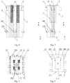
- Figs. 1-3 are schematic front, side and top cross-section views of a circulating fluidized bed boiler with a variable cross-section furnace according to an embodiment of the present invention, respectively;
- Figs. 4-5 are schematic cross-section views of a circulating fluidized bed boiler with a variable cross-section furnace according to the embodiment of the present invention at a lower level and an upper level, respectively.
- the water-cooled column 4 is formed by connecting membrane water-cooled walls 41, and comprises: a lower section A in a form of a single column at a lower portion of the furnace, an upper section in a form of double columns at middle and upper portions of the furnace.
- the upper section comprises a sub-column B and a sub-column C, and a transition section configured to connect the lower section A with the sub-sections B, C.
- the lower section A comprises: a water-cooled column front wall 401 and a water-cooled column rear wall 402 which are arranged opposite to each other and face towards the furnace front wall 21 and the furnace rear wall 22, respectively; and a water-cooled column left side wall 403 and a water-cooled column right side wall 404 which are arranged opposite to each other and face towards the furnace left side wall and the furnace right side wall, respectively.
- the sub-columns B and C of the upper section of the water-cooled column may be arranged side by side and have identical cross-section.
- the sub-column B comprises: a front wall 405 and a rear wall 406 which are arranged opposite to each other and in parallel with the furnace front wall 21, respectively; and a left side wall 407 and a right side wall 408 which are arranged opposite to each other and face towards the furnace left side wall 23 and the furnace right side wall 24, respectively.
- the sub-column C comprises: a front wall 409 and a rear wall 410 which are arranged opposite to each other and in parallel with the furnace rear wall 22, respectively; and a left side wall 411 and a right side wall 412 which are arranged opposite to each other and face towards the furnace left side wall 23 and the furnace right side wall 24, respectively.
- each of the sub-columns may have a cross-section shape chosen from a rectangle, a circle, a regular hexagon and a regular octagon.
- the water-cooled column 4 extends upward from the air distribution plate 1 to the ceiling 3 of the furnace.
- both the oppositely arranged side walls 403 and 404 of the lower section A at the lower portion of the water-cooled column 4 are inclined towards inner sides of the water-cooled column from a certain position above the air distribution plate 1 and below the secondary ports 400 inside the water-cooled column 4, so that the distance between the side walls 403 and 404 is reduced.
- both the side walls 403 and 404 turn to vertically extend upward to the ceiling 3.
- the oppositely arranged side walls 401 and 402 of the lower section A extend vertically to the ceiling 3 from bottom to top.
- an internal space of the water-cooled column is formed as a comb tooth-shaped space with two comb teeth, which are communicated with each other.
- Lower portions of the furnace front wall 21 and the furnace rear wall 22 are inclined outwardly from a certain level above the air distribution plate 1, and outer secondary air ports 220 are provided outside the outwardly inclined sections.
- Both the furnace left side wall 23 and the furnace right side wall 24 extend vertically from bottom to top, outer secondary air ports 220 are also provided outside lower portions of the side walls 23, 24.
- the furnace outlets 5 connected with the cyclone separator (not shown) are provided in upper portions of the furnace left side wall 23 and the furnace right side wall 24.
- platen heating surfaces 6 are provided at upper portions outside the left side wall 407 and the right side wall 408 of the sub-column B and outside the left side wall 411 and the right side wall 412 of the sub-column C.
- platen heating surfaces 6 may also be provided at upper portions outside the front wall 405 and the rear wall 406 of the sub-column B and outside the front wall 409 and the rear wall 410 of the sub-column C.
- the rear wall 406 of the sub-column B and the front wall 409 of the sub-column C extend vertically to the ceiling 3 from bottom to top.
- the front wall 405 of the sub-column B and the furnace front wall 21 are arranged in parallel with each other;
- the rear wall 406 of the sub-column B and the front wall 409 of the sub-column C are arranged in parallel with each other;
- the rear wall 410 of the sub-column C and the furnace rear wall 22 are arranged in parallel with each other;
- the left side wall 407 and the right side wall 408 of the sub-column B and the left side wall 411 and the right side wall 412 of the sub-column C are arranged in parallel with the furnace left side wall 23 and the furnace right side wall 24.
- Water-cooled wall tubes at left half of the rear wall 406 of the sub-column B are connected with water-cooled wall tubes at front portion of the left side wall 403 of the lower section A through connection tubes; water-cooled wall tubes at right half of the rear wall 406 of the sub-column B are connected with water-cooled wall tubes at front portion of the right side wall 404 of the lower section A through connection tubes.
- water-cooled wall tubes at left half of the front wall 409 of the sub-column C are connected with water-cooled wall tubes at rear portion of the left side wall 403 of the lower section A through connection tubes; water-cooled wall tubes at right half of the front wall 409 of the sub-column C are connected with water-cooled wall tubes at rear portion of the right side wall 404 of the lower section A through connection tubes.
- the lower section A at the lower portion of the furnace is transited to the upper section having double columns.
- Figs. 6-7 are schematic front and top cross-section views of a circulating fluidized bed boiler with a variable cross-section furnace according to another embodiment of the present invention, respectively. This embodiment is different from the previously described embodiment in a structure of the water-cooled column upper section, while the other structure is similar to the previously described embodiment.
- the front wall 401 and the rear wall 402 (referring to Fig. 4 ) of the lower section A, the front wall 405 and the rear wall 406 (referring to Fig. 5 ) of the sub-column B, the front wall 409 and the rear wall 410 (referring to Fig. 5 ) of the sub-column C extend vertically to the ceiling 3 from bottom to top.
- Lower portions of the furnace front wall 21 and the furnace rear wall 22 are inclined outwardly from a certain level above the air distribution plate 1, and outer secondary air ports 220 are provided on the inclined sections.
- the width between the left side wall 403 and the right side wall 404 (referring to Fig. 4 ) of the lower section A is identical to the width between the left side wall 407 and the right side wall 408 (referring to Fig. 5 ) of the sub-column B, and to the width between the left side wall 411 and the right side wall 412 (referring to Fig. 5 ) of the sub-column C.
- inner secondary air ports 400 are provided in inner sides of the left side wall 407 and the right side wall 408 of the sub-column B and in inner sides of the left side wall 411 and the right side wall 412 of the sub-column C at a certain level thereof.
- inner secondary air ports 400 may also be provided in the inner sides of the front wall 405 and the rear wall 406 of the sub-column B and in the inner sides of the front wall 409 and the rear wall 410 of the sub-column C.
- Lower portions of the furnace left side wall 23 and the furnace right side wall 24 are inclined outwardly from a certain level above the air distribution plate 1 to a predefined height, and then extend vertically to the ceiling 3 from bottom to top.
- Outer secondary air ports 220 are provided outside the inclined section of the lower portions of the furnace left side wall 23 and the furnace right side wall 24 at the same level as the inner secondary air ports 400 in the inner sides of the left and right side walls of the sub-columns B, C.
- Platen heating surfaces 6 are provided on outer sides of upper portions of the left side wall 407 and the right side wall 408 of the sub-column B and upper portions of the left side wall 411 and the right side wall 412 of the sub-column C.
- platen heating surfaces 6 may also be provided on inner sides of the furnace left side wall 23 and the furnace right side wall 24 between two adjacent furnace outlets 5, and provided on outer sides of upper portions of the front wall 405 and the rear wall 406 of the sub-column B and upper portions of the front wall 409 and the rear wall 410 of the sub-column C, according to requirements for heat absorption of the furnace.
- Figs. 8-10 are schematic front, side and top cross-section views of a circulating fluidized bed boiler with a variable cross-section furnace according to further another embodiment of the present invention, respectively;
- Fig. 11 is a schematic cross-section view of a circulating fluidized bed boiler with a variable cross-section furnace according to the embodiment of the present invention at an upper level. This embodiment is different from the embodiment shown in Figs. 1-3 in a structure of the upper section, while the other structure is similar to the first embodiment.
- the present invention provides another comb tooth type water-cooled column, wherein the lower section at a lower portion of the furnace is formed as a single column, which is connected to an upper section having three parallel columns at middle and upper portions of the furnace through a transition section.
- a comb tooth-shaped space with three comb teeth is formed inside the water-cooled column.
- Both the left and right side walls 403 and 404 (see Fig.4 ) of the lower section A are inclined towards inner sides of the water-cooled column from a certain level, and then extend vertically upward to the ceiling 3 from bottom to top after the inclined sections reach to a certain level.
- Inner secondary air ports 400 are provided in an inner side of each side of the inclined transition section of the water-cooled wall.
- the front wall 401 and the rear wall 402 (referring to Fig. 4 ) of the lower section A extend vertically upward to the ceiling 3 from bottom to top so as to form a front wall of a sub-column D and a rear wall of a sub-column F at an upper section of the water-cooled column at a certain level, respectively.
- Outer secondary air ports 220 are also provided outside the lower portions of the furnace front wall 21, the furnace rear wall 22, the left side wall 23 and the right side wall 24, at levels corresponding to the levels of the inner secondary air ports 400.
- the water-cooled wall tubes at the middle of the left and right side walls 403, 404 of the lower section A are inclined towards inner sides of the water-cooled column at a certain level above the air distribution plate 1 and extend to a predefined height, and then extend to form left and right side walls of the sub-columns D, E, F of the upper section, respectively.
- the cross-sections of the sub-columns D, E, F are in a rectangle shape, and have identical cross-section area.
- Inner secondary air ports 400 are provided on inner sides of lower portions of four membrane water-cooled walls of the sub-columns D, E, F, respectively.
- Outer secondary air ports 220 are provided outside respective furnace side walls at the same level as the inner secondary air ports 400.
- Platen heating surfaces 6 are provided on upper portions of outer sides of the left and right side walls of the sub-columns D, E, F of the upper section, and platen heating surfaces 6 may also be provided on upper portions of outer sides of the front wall of the sub-column D and the rear wall of the sub-column F.
- platen heating surfaces 6 may also be provided on upper portions of outer sides of the rear wall of the sub-column D, the front and rear walls of the sub-column E, and the front wall of the sub-column F.
- the present invention provides a water-cooled column used in a circulating fluidized bed boiler furnace, wherein the water-cooled column is formed by connecting membrane water-cooled walls, and the water-cooled column comprises: a lower section A configured to be a single column and provided with inner secondary air ports 400 on a side wall thereof; an upper section comprising a plurality of sub-columns B, C; D, E, F; and a transition section, through which the membrane water-cooled walls at the lower section A extend to the upper section, wherein the upper section is connected to the lower section by means of the transition section to form a flow passage for working medium of the water-cooled column, which run from the air distribution plate to the ceiling.
- Each of the sub-columns is formed by connecting extension portions extending upward from respective membrane water-cooled walls in the membrane water-cooled walls, which are connected to form the lower section, and the plurality of sub-columns are separated from each other.
- the upper section comprises two sub-columns B, C.
- the upper section comprises three sub-columns D, E, F arranged in a line and equidistantly spaced apart from each other.
- the upper section comprises four sub-columns, among which a cross-shaped gap is defined.
- a cross-shaped gap is defined.
- each of the sub-columns has an identical cross-section with any other sub-columns. Further, each of the sub-columns has an identical cross-section area with any other sub-columns.
- each of the sub-columns has a cross-section shape chosen from a rectangle, a circle, a regular hexagon and a regular octagon.
- additional inner secondary air ports 400 are provided on opposite side walls of at least a pair of adjacent sub-columns.
- the present invention also relates to a circulating fluidized bed boiler furnace, comprising furnace side walls, a ceiling 3, an air distribution plate 1 and a water-cooled column 4 provided between the air distribution plate 1 and the ceiling 3, wherein a furnace combustion space is enclosed by the water-cooled column side walls, the furnace side walls, the air distribution plate and the ceiling, inner secondary air ports 400 for injecting secondary air into the furnace combustion space are provided at a lower portion of the water-cooled column side walls, and outer secondary air ports 220 for injecting secondary air into the furnace combustion space are provided at a lower portion of the furnace side walls.
- an extended heating surface 6 is arranged outside at least one of the sub-columns.
- the present invention also relates to a circulating fluidized bed boiler, comprising the above described circulating fluidized bed boiler furnace.
- the water-cooled column is divided into a single column lower section and a multi-column upper section, and a transition section is provided between the upper section and the lower section.
- the upper section is connected with the lower section through the transition section, so that comb tooth-shaped communicated spaces are formed in the water-cooled column.
- the membrane-type wall tubes of the lower section extend upward to form the membrane-type wall tubes of the upper section, so that a flow passage for working medium in the water-cooled column is formed from the air distribution plate to the ceiling.
- a combustion space at the lower portion of the furnace where the lower section is located has an annular cross-section
- the air distribution plate also has an annular cross-section
- a combustion space at the middle and upper portion of the furnace where the upper section is located has a shape similar to the Chinese character " ", " " or the like.
Landscapes
- Engineering & Computer Science (AREA)
- Chemical & Material Sciences (AREA)
- Combustion & Propulsion (AREA)
- Mechanical Engineering (AREA)
- General Engineering & Computer Science (AREA)
- Physics & Mathematics (AREA)
- Thermal Sciences (AREA)
- Fluidized-Bed Combustion And Resonant Combustion (AREA)
Description
- The present invention relates to a circulating fluidized bed boiler, and more particularly, to a heating surface in a furnace of the circulating fluidized bed boiler.
- It is an inexorable trend for a circulating fluidized bed boiler technology to develop in a direction of large-scale equipment and high degree of parameterization. As the boiler capacity increases, the cross section of a furnace is also constantly increasing; as a result, secondary air injected from a wall surface into the furnace is difficult to reach the center of the furnace. At the same time, compared to the area increase of an evaporating heating surface in the furnace, the furnace volume is more significantly increased, which causes exothermic and endothermic imbalance and puts forward a new requirement for heating surface arrangement. In summary, the secondary air penetration and the furnace heating surface arrangement have become a major technology bottleneck, which constraints the circulating fluidized bed boiler from developing in the direction of large-scale equipment and high degree of parameterization.
- To solve the above technical problems, a Chinese patent
CN 101196297 A1 1 discloses a circulating fluidized bed boiler furnace with a water-cooled column, in which a water-cooled column formed by connecting membrane water-cooled walls is provided between an air distribution plate and a ceiling of the furnace to increase the furnace heating surface, and secondary air may be injected into the furnace combustion space through the water-cooled column. Since a secondary air pipe is needed to be placed inside the column, it is necessary to keep a certain amount of pipe arrangement and maintenance space. However, the cross-sections of the water-cooled column at different levels are kept constant, it therefore causes that all the internal space of the water-cooled column at various levels in an up-down direction is relatively larger, it further causes that a distance between the water-cooled column and an outer wall of the furnace is relatively small, especially the upper space of the furnace cannot meet the requirement for arranging a platen heating surface, and it brings about some difficult in distributing gas-solid flow in the furnace. - According to the invention, there is provided a water-cooled column used in a circulating fluidized bed boiler furnace, wherein the water-cooled column is formed by connecting membrane water-cooled walls, and the water-cooled column comprises: a lower section configured to be a single column and provided with inner secondary air ports on a side wall thereof; an upper section comprising a plurality of sub-columns; and a transition section, through which the membrane water-cooled walls at the lower section extend to the upper section, wherein each of the sub-columns is formed by connecting extension portions extending upward from respective membrane water-cooled walls in the membrane water-cooled walls, which are connected to form the lower section, and the plurality of sub-columns are separated from each other.
- Optionally, the upper section comprises two sub-columns.
- Optionally, the upper section comprises three sub-columns arranged in a line and equidistantly spaced apart from each other.
- Optionally, the upper section comprises four sub-columns, among which a cross-shaped gap is defined.
- Optionally, in the above described water-cooled column, each of the sub-columns has an identical cross-section with any other sub-columns. Further, each of the sub-columns has an identical cross-section area with any other sub-columns.
- Optionally, in the above described water-cooled column, each of the sub-columns has a cross-section shape chosen from a rectangle, a circle, a regular hexagon and a regular octagon.
- Optionally, in the above described water-cooled column, additional inner secondary air ports are provided on opposite side walls of at least a pair of adjacent sub-columns.
- The present invention also relates to a circulating fluidized bed boiler furnace, comprising furnace side walls, a ceiling, an air distribution plate and the above described water-cooled column provided between the air distribution plate and the ceiling, wherein a furnace combustion space is enclosed by the water-cooled column side walls, the furnace side walls, the air distribution plate and the ceiling, inner secondary air ports for injecting secondary air into the furnace combustion space are provided at a lower portion of the water-cooled column side walls, and outer secondary air ports for injecting secondary air into the furnace combustion space are provided at a lower portion of the furnace side walls.
- Optionally, an extended heating surface is arranged outside at least one of the sub-columns.
- The present invention also relates to a circulating fluidized bed boiler, comprising the above described circulating fluidized bed boiler furnace.
-
-
Figs. 1-3 are schematic front, side and top cross-section views of a circulating fluidized bed boiler with a variable cross-section furnace according to an embodiment of the present invention, respectively; -
Figs. 4-5 are schematic cross-section views of a circulating fluidized bed boiler with a variable cross-section furnace according to the embodiment of the present invention at a lower level and an upper level, respectively; -
Figs. 6-7 are schematic front and top cross-section views of a circulating fluidized bed boiler with a variable cross-section furnace according to another embodiment of the present invention, respectively; -
Figs. 8-10 are schematic front, side and top cross-section views of a circulating fluidized bed boiler with a variable cross-section furnace according to further another embodiment of the present invention, respectively; -
Fig. 11 is a schematic cross-section view of a circulating fluidized bed boiler with a variable cross-section furnace according to the above embodiment of the present invention at an upper level. - Exemplary embodiments of the present invention shown in the accompanying drawings will be described in detail below, wherein the same or similar reference number is intended to indicate the same or similar element. The embodiments described hereafter with reference to the accompanying drawings are exemplary, and are intended to explain the present invention, rather than limiting the present invention.
- Next, a circulating fluidized bed boiler with a variable cross-section furnace will be described with reference to
Figs. 1-11 . - As shown in
Figs. 1-11 , the cross-section of the furnace of the circulating fluidized bed boiler optionally presents a quadrangle, the circulating fluidized bed boiler comprises: anair distribution plate 1 provided at a bottom of the furnace, afurnace front wall 21, a furnacerear wall 22, a furnaceleft side wall 23 and a furnaceright side wall 24, aceiling 3,furnace outlets 5 and at least one water-cooledcolumn 4 provided between the air distribution plate and the ceiling, wherein thefurnace outlets 5 are connected with a cyclone separator (not shown). - In order to ensure that an arrangement space inside the water-cooled column is sufficient for secondary air tubes, a lower section A of the water-cooled column is configured to be a single column.
-
Figs. 1-3 are schematic front, side and top cross-section views of a circulating fluidized bed boiler with a variable cross-section furnace according to an embodiment of the present invention, respectively;Figs. 4-5 are schematic cross-section views of a circulating fluidized bed boiler with a variable cross-section furnace according to the embodiment of the present invention at a lower level and an upper level, respectively. - As shown in
Figs. 4-5 , the water-cooledcolumn 4 is formed by connecting membrane water-cooledwalls 41, and comprises: a lower section A in a form of a single column at a lower portion of the furnace, an upper section in a form of double columns at middle and upper portions of the furnace. The upper section comprises a sub-column B and a sub-column C, and a transition section configured to connect the lower section A with the sub-sections B, C. The lower section A comprises: a water-cooledcolumn front wall 401 and a water-cooled columnrear wall 402 which are arranged opposite to each other and face towards thefurnace front wall 21 and the furnacerear wall 22, respectively; and a water-cooled columnleft side wall 403 and a water-cooled columnright side wall 404 which are arranged opposite to each other and face towards the furnace left side wall and the furnace right side wall, respectively. The sub-columns B and C of the upper section of the water-cooled column may be arranged side by side and have identical cross-section. The sub-column B comprises: afront wall 405 and arear wall 406 which are arranged opposite to each other and in parallel with the furnacefront wall 21, respectively; and aleft side wall 407 and aright side wall 408 which are arranged opposite to each other and face towards the furnaceleft side wall 23 and the furnaceright side wall 24, respectively. The sub-column C comprises: afront wall 409 and arear wall 410 which are arranged opposite to each other and in parallel with the furnacerear wall 22, respectively; and aleft side wall 411 and aright side wall 412 which are arranged opposite to each other and face towards the furnaceleft side wall 23 and the furnaceright side wall 24, respectively. All the cross-sections of the lower section A as well as the sub-column B and the sub-column C are in a rectangle shape. It should be noted that each of the sub-columns may have a cross-section shape chosen from a rectangle, a circle, a regular hexagon and a regular octagon. - The water-cooled
column 4 extends upward from theair distribution plate 1 to theceiling 3 of the furnace. As the water-cooledcolumn 4 extends from bottom to top, both the oppositely arrangedside walls column 4 are inclined towards inner sides of the water-cooled column from a certain position above theair distribution plate 1 and below thesecondary ports 400 inside the water-cooledcolumn 4, so that the distance between theside walls side walls side walls ceiling 3. The oppositely arrangedside walls ceiling 3 from bottom to top. As a result, an internal space of the water-cooled column is formed as a comb tooth-shaped space with two comb teeth, which are communicated with each other. - Lower portions of the
furnace front wall 21 and the furnacerear wall 22 are inclined outwardly from a certain level above theair distribution plate 1, and outersecondary air ports 220 are provided outside the outwardly inclined sections. Both the furnaceleft side wall 23 and the furnaceright side wall 24 extend vertically from bottom to top, outersecondary air ports 220 are also provided outside lower portions of theside walls furnace outlets 5 connected with the cyclone separator (not shown) are provided in upper portions of the furnaceleft side wall 23 and the furnaceright side wall 24. - As shown in
Figs. 1-3 ,platen heating surfaces 6 are provided at upper portions outside theleft side wall 407 and theright side wall 408 of the sub-column B and outside theleft side wall 411 and theright side wall 412 of the sub-column C. - Optionally,
platen heating surfaces 6 may also be provided at upper portions outside thefront wall 405 and therear wall 406 of the sub-column B and outside thefront wall 409 and therear wall 410 of the sub-column C. - As shown in
Figs. 3-5 , therear wall 406 of the sub-column B and thefront wall 409 of the sub-column C extend vertically to theceiling 3 from bottom to top. Thefront wall 405 of the sub-column B and the furnacefront wall 21 are arranged in parallel with each other; therear wall 406 of the sub-column B and thefront wall 409 of the sub-column C are arranged in parallel with each other; therear wall 410 of the sub-column C and the furnacerear wall 22 are arranged in parallel with each other; theleft side wall 407 and theright side wall 408 of the sub-column B and theleft side wall 411 and theright side wall 412 of the sub-column C are arranged in parallel with the furnaceleft side wall 23 and the furnaceright side wall 24. - Water-cooled wall tubes at left half of the
rear wall 406 of the sub-column B are connected with water-cooled wall tubes at front portion of theleft side wall 403 of the lower section A through connection tubes; water-cooled wall tubes at right half of therear wall 406 of the sub-column B are connected with water-cooled wall tubes at front portion of theright side wall 404 of the lower section A through connection tubes. Similarly, water-cooled wall tubes at left half of thefront wall 409 of the sub-column C are connected with water-cooled wall tubes at rear portion of theleft side wall 403 of the lower section A through connection tubes; water-cooled wall tubes at right half of thefront wall 409 of the sub-column C are connected with water-cooled wall tubes at rear portion of theright side wall 404 of the lower section A through connection tubes. In this way, the lower section A at the lower portion of the furnace is transited to the upper section having double columns. -
Figs. 6-7 are schematic front and top cross-section views of a circulating fluidized bed boiler with a variable cross-section furnace according to another embodiment of the present invention, respectively. This embodiment is different from the previously described embodiment in a structure of the water-cooled column upper section, while the other structure is similar to the previously described embodiment. - As shown in
Figs. 6-7 , thefront wall 401 and the rear wall 402 (referring toFig. 4 ) of the lower section A, thefront wall 405 and the rear wall 406 (referring toFig. 5 ) of the sub-column B, thefront wall 409 and the rear wall 410 (referring toFig. 5 ) of the sub-column C extend vertically to theceiling 3 from bottom to top. Lower portions of thefurnace front wall 21 and the furnacerear wall 22 are inclined outwardly from a certain level above theair distribution plate 1, and outersecondary air ports 220 are provided on the inclined sections. - The width between the
left side wall 403 and the right side wall 404 (referring toFig. 4 ) of the lower section A is identical to the width between theleft side wall 407 and the right side wall 408 (referring toFig. 5 ) of the sub-column B, and to the width between theleft side wall 411 and the right side wall 412 (referring toFig. 5 ) of the sub-column C. - Advantageously, inner
secondary air ports 400 are provided in inner sides of theleft side wall 407 and theright side wall 408 of the sub-column B and in inner sides of theleft side wall 411 and theright side wall 412 of the sub-column C at a certain level thereof. Optionally, innersecondary air ports 400 may also be provided in the inner sides of thefront wall 405 and therear wall 406 of the sub-column B and in the inner sides of thefront wall 409 and therear wall 410 of the sub-column C. - Lower portions of the furnace
left side wall 23 and the furnaceright side wall 24 are inclined outwardly from a certain level above theair distribution plate 1 to a predefined height, and then extend vertically to theceiling 3 from bottom to top. Outersecondary air ports 220 are provided outside the inclined section of the lower portions of the furnace leftside wall 23 and the furnaceright side wall 24 at the same level as the innersecondary air ports 400 in the inner sides of the left and right side walls of the sub-columns B, C. - Platen heating surfaces 6 are provided on outer sides of upper portions of the
left side wall 407 and theright side wall 408 of the sub-column B and upper portions of theleft side wall 411 and theright side wall 412 of the sub-column C. - Optionally, platen heating surfaces 6 may also be provided on inner sides of the furnace left
side wall 23 and the furnaceright side wall 24 between twoadjacent furnace outlets 5, and provided on outer sides of upper portions of thefront wall 405 and therear wall 406 of the sub-column B and upper portions of thefront wall 409 and therear wall 410 of the sub-column C, according to requirements for heat absorption of the furnace. -
Figs. 8-10 are schematic front, side and top cross-section views of a circulating fluidized bed boiler with a variable cross-section furnace according to further another embodiment of the present invention, respectively;Fig. 11 is a schematic cross-section view of a circulating fluidized bed boiler with a variable cross-section furnace according to the embodiment of the present invention at an upper level. This embodiment is different from the embodiment shown inFigs. 1-3 in a structure of the upper section, while the other structure is similar to the first embodiment. - As shown in
Figs. 8-11 , in a case that a width of the furnace is large enough, in order to improve gas-solid blending and flow uniformity in a horizontal direction at the upper portion of the furnace, the present invention provides another comb tooth type water-cooled column, wherein the lower section at a lower portion of the furnace is formed as a single column, which is connected to an upper section having three parallel columns at middle and upper portions of the furnace through a transition section. As a result, a comb tooth-shaped space with three comb teeth is formed inside the water-cooled column. - Both the left and
right side walls 403 and 404 (seeFig.4 ) of the lower section A are inclined towards inner sides of the water-cooled column from a certain level, and then extend vertically upward to theceiling 3 from bottom to top after the inclined sections reach to a certain level. Innersecondary air ports 400 are provided in an inner side of each side of the inclined transition section of the water-cooled wall. Thefront wall 401 and the rear wall 402 (referring toFig. 4 ) of the lower section A extend vertically upward to theceiling 3 from bottom to top so as to form a front wall of a sub-column D and a rear wall of a sub-column F at an upper section of the water-cooled column at a certain level, respectively. - Outer
secondary air ports 220 are also provided outside the lower portions of thefurnace front wall 21, the furnacerear wall 22, theleft side wall 23 and theright side wall 24, at levels corresponding to the levels of the innersecondary air ports 400. - The water-cooled wall tubes at the middle of the left and
right side walls air distribution plate 1 and extend to a predefined height, and then extend to form left and right side walls of the sub-columns D, E, F of the upper section, respectively. - The cross-sections of the sub-columns D, E, F are in a rectangle shape, and have identical cross-section area. Inner
secondary air ports 400 are provided on inner sides of lower portions of four membrane water-cooled walls of the sub-columns D, E, F, respectively. Outersecondary air ports 220 are provided outside respective furnace side walls at the same level as the innersecondary air ports 400. - Platen heating surfaces 6 are provided on upper portions of outer sides of the left and right side walls of the sub-columns D, E, F of the upper section, and platen heating surfaces 6 may also be provided on upper portions of outer sides of the front wall of the sub-column D and the rear wall of the sub-column F.
- Optionally, platen heating surfaces 6 may also be provided on upper portions of outer sides of the rear wall of the sub-column D, the front and rear walls of the sub-column E, and the front wall of the sub-column F.
- In summary, the present invention provides a water-cooled column used in a circulating fluidized bed boiler furnace, wherein the water-cooled column is formed by connecting membrane water-cooled walls, and the water-cooled column comprises: a lower section A configured to be a single column and provided with inner
secondary air ports 400 on a side wall thereof; an upper section comprising a plurality of sub-columns B, C; D, E, F; and a transition section, through which the membrane water-cooled walls at the lower section A extend to the upper section, wherein the upper section is connected to the lower section by means of the transition section to form a flow passage for working medium of the water-cooled column, which run from the air distribution plate to the ceiling. Each of the sub-columns is formed by connecting extension portions extending upward from respective membrane water-cooled walls in the membrane water-cooled walls, which are connected to form the lower section, and the plurality of sub-columns are separated from each other. - Optionally, as shown in
Figs. 2-5 , the upper section comprises two sub-columns B, C. - Optionally, as shown in
Figs. 9-11 , the upper section comprises three sub-columns D, E, F arranged in a line and equidistantly spaced apart from each other. - Optionally, the upper section comprises four sub-columns, among which a cross-shaped gap is defined. However, such embodiment is not illustrated.
- Optionally, in the above described water-cooled column, each of the sub-columns has an identical cross-section with any other sub-columns. Further, each of the sub-columns has an identical cross-section area with any other sub-columns.
- Optionally, in the above described water-cooled column, each of the sub-columns has a cross-section shape chosen from a rectangle, a circle, a regular hexagon and a regular octagon.
- Optionally, in the above described water-cooled column, as shown in
Figs. 3 and7 , additional innersecondary air ports 400 are provided on opposite side walls of at least a pair of adjacent sub-columns. - The present invention also relates to a circulating fluidized bed boiler furnace, comprising furnace side walls, a
ceiling 3, anair distribution plate 1 and a water-cooledcolumn 4 provided between theair distribution plate 1 and theceiling 3, wherein a furnace combustion space is enclosed by the water-cooled column side walls, the furnace side walls, the air distribution plate and the ceiling, innersecondary air ports 400 for injecting secondary air into the furnace combustion space are provided at a lower portion of the water-cooled column side walls, and outersecondary air ports 220 for injecting secondary air into the furnace combustion space are provided at a lower portion of the furnace side walls. - Optionally, an
extended heating surface 6 is arranged outside at least one of the sub-columns. - The present invention also relates to a circulating fluidized bed boiler, comprising the above described circulating fluidized bed boiler furnace.
- In the present invention, by means of the comb tooth type water-cooled column provided in the furnace, it is beneficial to strengthen lateral blending of particles in a horizontal direction of the furnace and full combustion, causes improved uniformity of the lateral gas-solid two phase flow in the furnace, and effectively increases a gas-solid two phase annular flow space in the furnace. As a result, more extended heating surfaces may be arranged to effectively absorb excessive heat in the furnace due to increased steam parameter, and achieve the objective of controlling bed temperature and furnace outlet flue gas temperature. In the present invention, the water-cooled column is divided into a single column lower section and a multi-column upper section, and a transition section is provided between the upper section and the lower section. Specifically, the upper section is connected with the lower section through the transition section, so that comb tooth-shaped communicated spaces are formed in the water-cooled column. Further, the membrane-type wall tubes of the lower section extend upward to form the membrane-type wall tubes of the upper section, so that a flow passage for working medium in the water-cooled column is formed from the air distribution plate to the ceiling. Moreover, a combustion space at the lower portion of the furnace where the lower section is located has an annular cross-section, and the air distribution plate also has an annular cross-section, while a combustion space at the middle and upper portion of the furnace where the upper section is located has a shape similar to the Chinese character "", "
 " or the like.
- The large-scale circulating fluidized bed boiler furnace according to the present invention may achieve at least one of the following advantages:
- 1) the lower section of the water-cooled column is a single column, the internal space of which is relatively rich to conveniently arrange secondary air pipes and implement maintenance;
- 2) the water-cooled wall tube of the lower section formed as a single column extends upward in a way of bent pipe to form a multi-column upper section of the water-cooled column, and a sum of perimeters of the cross-sections of various columns of the upper section is substantially equal to a perimeter of the cross-section of the single column of the lower section while the internal space of the formed water-cooled column at the upper section is significantly less than at the lower section, which enables the combustion space, the material flow and the blending space at the middle and upper portion of the furnace to be increased or improved, in contrast to that of the furnace with a constant cross-section water-cooled column. As a result, the flow condition at the middle and upper portion of the furnace becomes better, and it facilitates improving flow uniformity between various circulation loops of the large-scale boiler with a plurality of separator, return feeders, thereby effectively reducing thermal deviation between the platen heating surfaces in the furnace and between the plurality of the cyclone separators, and effectively reducing the risk of water-cooled tube bursting in the furnace, further facilitating improving the operation safety of the boiler;
- 3) more extended heating surfaces may be arranged on the side walls of the upper section with multi-columns, thereby it highly facilitates arranging the heating surfaces in the furnace of the large-scale boiler, so as to achieve the objective of controlling bed temperature and furnace outlet flue gas temperature, furthermore, the gas-solid blending is more strong, and the gas-solid flow is more uniform.
- Although the embodiments of the present invention have been shown and described, it should be appreciated by the person skilled in the art that changes may be made to these embodiments without departing from the scope of the invention which is defined by the appended claims.
Claims (11)
- A water-cooled column (4) for a circulating fluidized bed boiler furnace, wherein the water-cooled column (4) is formed by connecting membrane water-cooled walls (41), and characterized in that the water-cooled column (4) comprises:a lower section (A) configured to be a single column and provided with inner secondary air ports (400) on a side wall thereof;an upper section comprising a plurality of sub-columns (B-F); anda transition section, through which the membrane water-cooled walls (41) at the lower section (A) extend to the upper section,wherein each of the sub-columns (B-F) is formed by connecting extension portions extending upward from respective membrane water-cooled walls (41) in the membrane water-cooled walls which are connected to form the lower section (A), and the plurality of sub-columns (B-F) are separated from each other.
- The water-cooled column (4) according to claim 1, wherein the upper section comprises two sub-columns (B, C).
- The water-cooled column (4) according to claim 1, wherein the upper section comprises three sub-columns (D, E, F) arranged in a line and equidistantly spaced apart from each other.
- The water-cooled column (4) according to claim 1, wherein the upper section comprises four sub-columns, among which a cross-shaped gap is defined.
- The water-cooled column (4) according to any one of claims 1-4, wherein each of the sub-columns has an identical cross-section with any other sub-columns.
- The water-cooled column (4) according to claim 5, wherein each of the sub-columns has an identical cross-section area with any other sub-columns.
- The water-cooled column (4) according to any one of claims 1-4, wherein each of the sub-columns has a cross-section shape chosen from a rectangle, a circle, a regular hexagon and a regular octagon.
- The water-cooled column (4) according to any one of claims 1-4, wherein additional inner secondary air ports (400) are provided on opposite side walls of at least a pair of adjacent sub-columns.
- A circulating fluidized bed boiler furnace, comprising furnace side walls (21-24), a ceiling (3), an air distribution plate (1) and a water-cooled column (4) provided between the air distribution plate (1) and the ceiling (3), wherein the water-cooled column (4) is formed by connecting side walls which are formed by membrane water-cooled walls (41), a furnace combustion space is enclosed by the water-cooled column side walls, the furnace side walls (21-24), the air distribution plate (1) and the ceiling (3), inner secondary air ports (400) for injecting secondary air into the furnace combustion space are provided at a lower portion of the water-cooled column side walls, and outer secondary air ports (220) for injecting secondary air into the furnace combustion space are provided at a lower portion of the furnace side walls (21-24),
wherein the water-cooled column (4) is the water-cooled column according to any one of claims 1-8. - The circulating fluidized bed boiler furnace according to claim 9, wherein an extended heating surface is arranged outside at least one of the sub-columns.
- A circulating fluidized bed boiler, comprising the circulating fluidized bed boiler furnace according to claims 9 or 10.
Priority Applications (1)
| Application Number | Priority Date | Filing Date | Title |
|---|---|---|---|
| PL14871950T PL3086037T3 (en) | 2013-12-20 | 2014-10-13 | Water-cooled column and hearth having same |
Applications Claiming Priority (2)
| Application Number | Priority Date | Filing Date | Title |
|---|---|---|---|
| CN201310712004.8A CN104728856B (en) | 2013-12-20 | 2013-12-20 | Interdigitated electrode structure water-cooled column and the burner hearth with this water-cooled column |
| PCT/CN2014/088490 WO2015090104A1 (en) | 2013-12-20 | 2014-10-13 | Comb teeth type water-cooled column and hearth having same |
Publications (3)
| Publication Number | Publication Date |
|---|---|
| EP3086037A1 EP3086037A1 (en) | 2016-10-26 |
| EP3086037A4 EP3086037A4 (en) | 2017-08-09 |
| EP3086037B1 true EP3086037B1 (en) | 2021-12-01 |
Family
ID=53402076
Family Applications (1)
| Application Number | Title | Priority Date | Filing Date |
|---|---|---|---|
| EP14871950.3A Active EP3086037B1 (en) | 2013-12-20 | 2014-10-13 | Water-cooled column and hearth having same |
Country Status (6)
| Country | Link |
|---|---|
| US (1) | US10495298B2 (en) |
| EP (1) | EP3086037B1 (en) |
| KR (1) | KR102091502B1 (en) |
| CN (1) | CN104728856B (en) |
| PL (1) | PL3086037T3 (en) |
| WO (1) | WO2015090104A1 (en) |
Families Citing this family (2)
| Publication number | Priority date | Publication date | Assignee | Title |
|---|---|---|---|---|
| CN110056868A (en) * | 2019-04-24 | 2019-07-26 | 哈尔滨理工大学 | A kind of automatic cooling bed of intermediate air inlet |
| CN112443833B (en) | 2019-09-05 | 2023-01-06 | 中国科学院工程热物理研究所 | Pulverized coal fired boiler with bottom-mounted burner and control method thereof |
Family Cites Families (19)
| Publication number | Priority date | Publication date | Assignee | Title |
|---|---|---|---|---|
| AT339344B (en) * | 1972-11-16 | 1977-10-10 | Waagner Biro Ag | PIPE BUNDLE STEAM GENERATORS, IN PARTICULAR FOR NUCLEAR POWER PLANTS |
| US4253425A (en) * | 1979-01-31 | 1981-03-03 | Foster Wheeler Energy Corporation | Internal dust recirculation system for a fluidized bed heat exchanger |
| CA2032711C (en) | 1990-12-19 | 1994-02-01 | George Cooke | Boiler |
| US5140950A (en) * | 1991-05-15 | 1992-08-25 | Foster Wheeler Energy Corporation | Fluidized bed combustion system and method having an integral recycle heat exchanger with recycle rate control and backflow sealing |
| AT401287B (en) | 1994-10-17 | 1996-07-25 | Austrian Energy & Environment | COOLING SURFACE LINING |
| US5678497A (en) * | 1996-04-30 | 1997-10-21 | Foster Wheeler Energy International, Inc. | Apparatus for distributing secondary air into a large scale circulating fluidized bed |
| US5836257A (en) * | 1996-12-03 | 1998-11-17 | Mcdermott Technology, Inc. | Circulating fluidized bed furnace/reactor with an integral secondary air plenum |
| FI105499B (en) * | 1998-11-20 | 2000-08-31 | Foster Wheeler Energia Oy | Process and apparatus in fluidized bed reactor |
| US6532905B2 (en) * | 2001-07-17 | 2003-03-18 | The Babcock & Wilcox Company | CFB with controllable in-bed heat exchanger |
| US7244400B2 (en) * | 2003-11-25 | 2007-07-17 | Foster Wheeler Energy Corporation | Fluidized bed reactor system having an exhaust gas plenum |
| CN100523606C (en) | 2006-12-07 | 2009-08-05 | 中国科学院工程热物理研究所 | Circulating fluidized bed boiler hearth with water-cooling column |
| CN101614390A (en) * | 2006-12-07 | 2009-12-30 | 中国科学院工程热物理研究所 | Circulating fluidized bed boiler furnace with water cooling column |
| CN100575782C (en) * | 2007-02-07 | 2009-12-30 | 中国科学院工程热物理研究所 | Circulating fluidized bed boiler furnace with heating screen |
| CN101457304B (en) | 2008-12-31 | 2011-04-27 | 邓小宝 | Central reverse flame interior heat storing type energy-saving high efficiency furnace and tank integrated reducing furnace system |
| US8622029B2 (en) * | 2009-09-30 | 2014-01-07 | Babcock & Wilcox Power Generation Group, Inc. | Circulating fluidized bed (CFB) with in-furnace secondary air nozzles |
| CN101718430B (en) * | 2009-12-22 | 2011-05-04 | 浙江大学 | Cross heating screen with secondary air jet for circulating fluidized bed boiler |
| CN102226518B (en) * | 2011-02-01 | 2013-03-06 | 中国科学院工程热物理研究所 | Large-scale circulating fluidized bed boiler |
| RS56360B1 (en) * | 2012-03-20 | 2017-12-29 | General Electric Technology Gmbh | Circulating fluidized bed boiler |
| CN102997231B (en) * | 2012-12-31 | 2015-06-24 | 中国科学院工程热物理研究所 | Large circulating fluidized bed boiler, air distribution device and air distribution device assembly |
-
2013
- 2013-12-20 CN CN201310712004.8A patent/CN104728856B/en active Active
-
2014
- 2014-10-13 PL PL14871950T patent/PL3086037T3/en unknown
- 2014-10-13 KR KR1020167019115A patent/KR102091502B1/en active Active
- 2014-10-13 EP EP14871950.3A patent/EP3086037B1/en active Active
- 2014-10-13 WO PCT/CN2014/088490 patent/WO2015090104A1/en not_active Ceased
- 2014-10-13 US US15/104,959 patent/US10495298B2/en active Active
Non-Patent Citations (1)
| Title |
|---|
| None * |
Also Published As
| Publication number | Publication date |
|---|---|
| KR102091502B1 (en) | 2020-03-23 |
| EP3086037A4 (en) | 2017-08-09 |
| KR20160120718A (en) | 2016-10-18 |
| US10495298B2 (en) | 2019-12-03 |
| EP3086037A1 (en) | 2016-10-26 |
| PL3086037T3 (en) | 2022-04-04 |
| WO2015090104A1 (en) | 2015-06-25 |
| CN104728856A (en) | 2015-06-24 |
| CN104728856B (en) | 2017-03-01 |
| US20160320051A1 (en) | 2016-11-03 |
Similar Documents
| Publication | Publication Date | Title |
|---|---|---|
| EP2672179B1 (en) | Large-scale circulating fluidized bed boiler | |
| WO2017088742A1 (en) | Water wall of supercritical circulating fluidized bed boiler having high flow stability at low load, and method of realizing low mass flow rate | |
| KR101667503B1 (en) | Large-size Circulating Fluidized Bed Boiler, Air Distributor and Air Distributor Assembly | |
| EP2634484A1 (en) | Circulating fluidized bed boiler | |
| BR112015031697B1 (en) | Liquid mixing collector, use and method and heat exchange or mass transfer column | |
| US10495298B2 (en) | Comb tooth type water-cooled column and furnace having the same | |
| KR101940356B1 (en) | Anti-clogging steam generator tube bundle | |
| TW201723304A (en) | Tube arrangement in a once-through horizontal evaporator | |
| US11603989B2 (en) | Circulating fluidized bed boiler with a loopseal heat exchanger | |
| JP3990202B2 (en) | Internal heat exchange distillation column | |
| CN215136897U (en) | For CO2Desorption falling film reboiler | |
| EP3045809B1 (en) | Circulating fluidized bed boiler furnace having a variable cross-section water-cooled cylinder | |
| KR101378347B1 (en) | Steam generation boiler | |
| CN105698165B (en) | A kind of chamber structure of CFBB | |
| CN205897096U (en) | Circulating fluidized bed boiler furnace curtain wall arrangement structure | |
| CN103216809B (en) | Circulating fluidized bed boiler with at least one centralized downcomer arranged in hearth | |
| CN206891195U (en) | Pyrolysis oven | |
| JP6173797B2 (en) | Heat exchanger and water heater | |
| JP2013066841A (en) | Steam flow control system with split bundles in a multi-effect freshwater generator | |
| JP2009041907A (en) | Regenerator for absorption water chiller-heater | |
| CN102226646B (en) | Hearth structure for improving heat exchange efficiency of flame-free heating section of industrial furnace | |
| JP4925853B2 (en) | Reactor | |
| JPH02229886A (en) | Cracking furnace for hydrocarbon | |
| CN108827042A (en) | A kind of finned tube fluidized bed heat collector | |
| JP2011226678A (en) | Fluid heating device |
Legal Events
| Date | Code | Title | Description |
|---|---|---|---|
| PUAI | Public reference made under article 153(3) epc to a published international application that has entered the european phase |
Free format text: ORIGINAL CODE: 0009012 |
|
| 17P | Request for examination filed |
Effective date: 20160615 |
|
| AK | Designated contracting states |
Kind code of ref document: A1 Designated state(s): AL AT BE BG CH CY CZ DE DK EE ES FI FR GB GR HR HU IE IS IT LI LT LU LV MC MK MT NL NO PL PT RO RS SE SI SK SM TR |
|
| AX | Request for extension of the european patent |
Extension state: BA ME |
|
| DAX | Request for extension of the european patent (deleted) | ||
| A4 | Supplementary search report drawn up and despatched |
Effective date: 20170712 |
|
| RIC1 | Information provided on ipc code assigned before grant |
Ipc: F22B 31/00 20060101ALI20170706BHEP Ipc: F23C 10/10 20060101AFI20170706BHEP |
|
| STAA | Information on the status of an ep patent application or granted ep patent |
Free format text: STATUS: EXAMINATION IS IN PROGRESS |
|
| 17Q | First examination report despatched |
Effective date: 20200710 |
|
| GRAP | Despatch of communication of intention to grant a patent |
Free format text: ORIGINAL CODE: EPIDOSNIGR1 |
|
| STAA | Information on the status of an ep patent application or granted ep patent |
Free format text: STATUS: GRANT OF PATENT IS INTENDED |
|
| INTG | Intention to grant announced |
Effective date: 20210714 |
|
| GRAS | Grant fee paid |
Free format text: ORIGINAL CODE: EPIDOSNIGR3 |
|
| GRAA | (expected) grant |
Free format text: ORIGINAL CODE: 0009210 |
|
| STAA | Information on the status of an ep patent application or granted ep patent |
Free format text: STATUS: THE PATENT HAS BEEN GRANTED |
|
| AK | Designated contracting states |
Kind code of ref document: B1 Designated state(s): AL AT BE BG CH CY CZ DE DK EE ES FI FR GB GR HR HU IE IS IT LI LT LU LV MC MK MT NL NO PL PT RO RS SE SI SK SM TR |
|
| REG | Reference to a national code |
Ref country code: GB Ref legal event code: FG4D |
|
| REG | Reference to a national code |
Ref country code: AT Ref legal event code: REF Ref document number: 1452104 Country of ref document: AT Kind code of ref document: T Effective date: 20211215 Ref country code: CH Ref legal event code: EP |
|
| REG | Reference to a national code |
Ref country code: IE Ref legal event code: FG4D |
|
| REG | Reference to a national code |
Ref country code: DE Ref legal event code: R096 Ref document number: 602014081578 Country of ref document: DE |
|
| REG | Reference to a national code |
Ref country code: LT Ref legal event code: MG9D |
|
| REG | Reference to a national code |
Ref country code: NL Ref legal event code: MP Effective date: 20211201 |
|
| REG | Reference to a national code |
Ref country code: AT Ref legal event code: MK05 Ref document number: 1452104 Country of ref document: AT Kind code of ref document: T Effective date: 20211201 |
|
| PG25 | Lapsed in a contracting state [announced via postgrant information from national office to epo] |
Ref country code: RS Free format text: LAPSE BECAUSE OF FAILURE TO SUBMIT A TRANSLATION OF THE DESCRIPTION OR TO PAY THE FEE WITHIN THE PRESCRIBED TIME-LIMIT Effective date: 20211201 Ref country code: LT Free format text: LAPSE BECAUSE OF FAILURE TO SUBMIT A TRANSLATION OF THE DESCRIPTION OR TO PAY THE FEE WITHIN THE PRESCRIBED TIME-LIMIT Effective date: 20211201 Ref country code: FI Free format text: LAPSE BECAUSE OF FAILURE TO SUBMIT A TRANSLATION OF THE DESCRIPTION OR TO PAY THE FEE WITHIN THE PRESCRIBED TIME-LIMIT Effective date: 20211201 Ref country code: BG Free format text: LAPSE BECAUSE OF FAILURE TO SUBMIT A TRANSLATION OF THE DESCRIPTION OR TO PAY THE FEE WITHIN THE PRESCRIBED TIME-LIMIT Effective date: 20220301 Ref country code: AT Free format text: LAPSE BECAUSE OF FAILURE TO SUBMIT A TRANSLATION OF THE DESCRIPTION OR TO PAY THE FEE WITHIN THE PRESCRIBED TIME-LIMIT Effective date: 20211201 |
|
| PG25 | Lapsed in a contracting state [announced via postgrant information from national office to epo] |
Ref country code: SE Free format text: LAPSE BECAUSE OF FAILURE TO SUBMIT A TRANSLATION OF THE DESCRIPTION OR TO PAY THE FEE WITHIN THE PRESCRIBED TIME-LIMIT Effective date: 20211201 Ref country code: NO Free format text: LAPSE BECAUSE OF FAILURE TO SUBMIT A TRANSLATION OF THE DESCRIPTION OR TO PAY THE FEE WITHIN THE PRESCRIBED TIME-LIMIT Effective date: 20220301 Ref country code: LV Free format text: LAPSE BECAUSE OF FAILURE TO SUBMIT A TRANSLATION OF THE DESCRIPTION OR TO PAY THE FEE WITHIN THE PRESCRIBED TIME-LIMIT Effective date: 20211201 Ref country code: HR Free format text: LAPSE BECAUSE OF FAILURE TO SUBMIT A TRANSLATION OF THE DESCRIPTION OR TO PAY THE FEE WITHIN THE PRESCRIBED TIME-LIMIT Effective date: 20211201 Ref country code: GR Free format text: LAPSE BECAUSE OF FAILURE TO SUBMIT A TRANSLATION OF THE DESCRIPTION OR TO PAY THE FEE WITHIN THE PRESCRIBED TIME-LIMIT Effective date: 20220302 Ref country code: ES Free format text: LAPSE BECAUSE OF FAILURE TO SUBMIT A TRANSLATION OF THE DESCRIPTION OR TO PAY THE FEE WITHIN THE PRESCRIBED TIME-LIMIT Effective date: 20211201 |
|
| PG25 | Lapsed in a contracting state [announced via postgrant information from national office to epo] |
Ref country code: NL Free format text: LAPSE BECAUSE OF FAILURE TO SUBMIT A TRANSLATION OF THE DESCRIPTION OR TO PAY THE FEE WITHIN THE PRESCRIBED TIME-LIMIT Effective date: 20211201 |
|
| PG25 | Lapsed in a contracting state [announced via postgrant information from national office to epo] |
Ref country code: SM Free format text: LAPSE BECAUSE OF FAILURE TO SUBMIT A TRANSLATION OF THE DESCRIPTION OR TO PAY THE FEE WITHIN THE PRESCRIBED TIME-LIMIT Effective date: 20211201 Ref country code: SK Free format text: LAPSE BECAUSE OF FAILURE TO SUBMIT A TRANSLATION OF THE DESCRIPTION OR TO PAY THE FEE WITHIN THE PRESCRIBED TIME-LIMIT Effective date: 20211201 Ref country code: RO Free format text: LAPSE BECAUSE OF FAILURE TO SUBMIT A TRANSLATION OF THE DESCRIPTION OR TO PAY THE FEE WITHIN THE PRESCRIBED TIME-LIMIT Effective date: 20211201 Ref country code: PT Free format text: LAPSE BECAUSE OF FAILURE TO SUBMIT A TRANSLATION OF THE DESCRIPTION OR TO PAY THE FEE WITHIN THE PRESCRIBED TIME-LIMIT Effective date: 20220401 Ref country code: EE Free format text: LAPSE BECAUSE OF FAILURE TO SUBMIT A TRANSLATION OF THE DESCRIPTION OR TO PAY THE FEE WITHIN THE PRESCRIBED TIME-LIMIT Effective date: 20211201 Ref country code: CZ Free format text: LAPSE BECAUSE OF FAILURE TO SUBMIT A TRANSLATION OF THE DESCRIPTION OR TO PAY THE FEE WITHIN THE PRESCRIBED TIME-LIMIT Effective date: 20211201 |
|
| REG | Reference to a national code |
Ref country code: DE Ref legal event code: R097 Ref document number: 602014081578 Country of ref document: DE |
|
| PG25 | Lapsed in a contracting state [announced via postgrant information from national office to epo] |
Ref country code: IS Free format text: LAPSE BECAUSE OF FAILURE TO SUBMIT A TRANSLATION OF THE DESCRIPTION OR TO PAY THE FEE WITHIN THE PRESCRIBED TIME-LIMIT Effective date: 20220401 |
|
| PLBE | No opposition filed within time limit |
Free format text: ORIGINAL CODE: 0009261 |
|
| STAA | Information on the status of an ep patent application or granted ep patent |
Free format text: STATUS: NO OPPOSITION FILED WITHIN TIME LIMIT |
|
| PG25 | Lapsed in a contracting state [announced via postgrant information from national office to epo] |
Ref country code: DK Free format text: LAPSE BECAUSE OF FAILURE TO SUBMIT A TRANSLATION OF THE DESCRIPTION OR TO PAY THE FEE WITHIN THE PRESCRIBED TIME-LIMIT Effective date: 20211201 Ref country code: AL Free format text: LAPSE BECAUSE OF FAILURE TO SUBMIT A TRANSLATION OF THE DESCRIPTION OR TO PAY THE FEE WITHIN THE PRESCRIBED TIME-LIMIT Effective date: 20211201 |
|
| 26N | No opposition filed |
Effective date: 20220902 |
|
| PG25 | Lapsed in a contracting state [announced via postgrant information from national office to epo] |
Ref country code: SI Free format text: LAPSE BECAUSE OF FAILURE TO SUBMIT A TRANSLATION OF THE DESCRIPTION OR TO PAY THE FEE WITHIN THE PRESCRIBED TIME-LIMIT Effective date: 20211201 |
|
| PG25 | Lapsed in a contracting state [announced via postgrant information from national office to epo] |
Ref country code: MC Free format text: LAPSE BECAUSE OF FAILURE TO SUBMIT A TRANSLATION OF THE DESCRIPTION OR TO PAY THE FEE WITHIN THE PRESCRIBED TIME-LIMIT Effective date: 20211201 Ref country code: IT Free format text: LAPSE BECAUSE OF FAILURE TO SUBMIT A TRANSLATION OF THE DESCRIPTION OR TO PAY THE FEE WITHIN THE PRESCRIBED TIME-LIMIT Effective date: 20211201 |
|
| REG | Reference to a national code |
Ref country code: CH Ref legal event code: PL |
|
| REG | Reference to a national code |
Ref country code: BE Ref legal event code: MM Effective date: 20221031 |
|
| GBPC | Gb: european patent ceased through non-payment of renewal fee |
Effective date: 20221013 |
|
| PG25 | Lapsed in a contracting state [announced via postgrant information from national office to epo] |
Ref country code: LU Free format text: LAPSE BECAUSE OF NON-PAYMENT OF DUE FEES Effective date: 20221013 |
|
| PG25 | Lapsed in a contracting state [announced via postgrant information from national office to epo] |
Ref country code: LI Free format text: LAPSE BECAUSE OF NON-PAYMENT OF DUE FEES Effective date: 20221031 Ref country code: CH Free format text: LAPSE BECAUSE OF NON-PAYMENT OF DUE FEES Effective date: 20221031 |
|
| PG25 | Lapsed in a contracting state [announced via postgrant information from national office to epo] |
Ref country code: BE Free format text: LAPSE BECAUSE OF NON-PAYMENT OF DUE FEES Effective date: 20221031 |
|
| PG25 | Lapsed in a contracting state [announced via postgrant information from national office to epo] |
Ref country code: IE Free format text: LAPSE BECAUSE OF NON-PAYMENT OF DUE FEES Effective date: 20221013 Ref country code: GB Free format text: LAPSE BECAUSE OF NON-PAYMENT OF DUE FEES Effective date: 20221013 |
|
| PG25 | Lapsed in a contracting state [announced via postgrant information from national office to epo] |
Ref country code: HU Free format text: LAPSE BECAUSE OF FAILURE TO SUBMIT A TRANSLATION OF THE DESCRIPTION OR TO PAY THE FEE WITHIN THE PRESCRIBED TIME-LIMIT; INVALID AB INITIO Effective date: 20141013 |
|
| PG25 | Lapsed in a contracting state [announced via postgrant information from national office to epo] |
Ref country code: CY Free format text: LAPSE BECAUSE OF FAILURE TO SUBMIT A TRANSLATION OF THE DESCRIPTION OR TO PAY THE FEE WITHIN THE PRESCRIBED TIME-LIMIT Effective date: 20211201 |
|
| PG25 | Lapsed in a contracting state [announced via postgrant information from national office to epo] |
Ref country code: MK Free format text: LAPSE BECAUSE OF FAILURE TO SUBMIT A TRANSLATION OF THE DESCRIPTION OR TO PAY THE FEE WITHIN THE PRESCRIBED TIME-LIMIT Effective date: 20211201 |
|
| PG25 | Lapsed in a contracting state [announced via postgrant information from national office to epo] |
Ref country code: MT Free format text: LAPSE BECAUSE OF FAILURE TO SUBMIT A TRANSLATION OF THE DESCRIPTION OR TO PAY THE FEE WITHIN THE PRESCRIBED TIME-LIMIT Effective date: 20211201 |
|
| PGFP | Annual fee paid to national office [announced via postgrant information from national office to epo] |
Ref country code: TR Payment date: 20250929 Year of fee payment: 12 |
|
| PGFP | Annual fee paid to national office [announced via postgrant information from national office to epo] |
Ref country code: DE Payment date: 20251014 Year of fee payment: 12 |
|
| PGFP | Annual fee paid to national office [announced via postgrant information from national office to epo] |
Ref country code: FR Payment date: 20251013 Year of fee payment: 12 |
|
| PGFP | Annual fee paid to national office [announced via postgrant information from national office to epo] |
Ref country code: PL Payment date: 20251001 Year of fee payment: 12 |