EP3085987A1 - Damper - Google Patents
Damper Download PDFInfo
- Publication number
- EP3085987A1 EP3085987A1 EP14870932.2A EP14870932A EP3085987A1 EP 3085987 A1 EP3085987 A1 EP 3085987A1 EP 14870932 A EP14870932 A EP 14870932A EP 3085987 A1 EP3085987 A1 EP 3085987A1
- Authority
- EP
- European Patent Office
- Prior art keywords
- piston
- housing
- seal member
- slider
- damper
- Prior art date
- Legal status (The legal status is an assumption and is not a legal conclusion. Google has not performed a legal analysis and makes no representation as to the accuracy of the status listed.)
- Granted
Links
Images





Classifications
-
- F—MECHANICAL ENGINEERING; LIGHTING; HEATING; WEAPONS; BLASTING
- F16—ENGINEERING ELEMENTS AND UNITS; GENERAL MEASURES FOR PRODUCING AND MAINTAINING EFFECTIVE FUNCTIONING OF MACHINES OR INSTALLATIONS; THERMAL INSULATION IN GENERAL
- F16F—SPRINGS; SHOCK-ABSORBERS; MEANS FOR DAMPING VIBRATION
- F16F9/00—Springs, vibration-dampers, shock-absorbers, or similarly-constructed movement-dampers using a fluid or the equivalent as damping medium
- F16F9/02—Springs, vibration-dampers, shock-absorbers, or similarly-constructed movement-dampers using a fluid or the equivalent as damping medium using gas only or vacuum
- F16F9/0209—Telescopic
- F16F9/0218—Mono-tubular units
-
- F—MECHANICAL ENGINEERING; LIGHTING; HEATING; WEAPONS; BLASTING
- F16—ENGINEERING ELEMENTS AND UNITS; GENERAL MEASURES FOR PRODUCING AND MAINTAINING EFFECTIVE FUNCTIONING OF MACHINES OR INSTALLATIONS; THERMAL INSULATION IN GENERAL
- F16F—SPRINGS; SHOCK-ABSORBERS; MEANS FOR DAMPING VIBRATION
- F16F9/00—Springs, vibration-dampers, shock-absorbers, or similarly-constructed movement-dampers using a fluid or the equivalent as damping medium
- F16F9/02—Springs, vibration-dampers, shock-absorbers, or similarly-constructed movement-dampers using a fluid or the equivalent as damping medium using gas only or vacuum
-
- A—HUMAN NECESSITIES
- A47—FURNITURE; DOMESTIC ARTICLES OR APPLIANCES; COFFEE MILLS; SPICE MILLS; SUCTION CLEANERS IN GENERAL
- A47B—TABLES; DESKS; OFFICE FURNITURE; CABINETS; DRAWERS; GENERAL DETAILS OF FURNITURE
- A47B88/00—Drawers for tables, cabinets or like furniture; Guides for drawers
- A47B88/50—Safety devices or the like for drawers
- A47B88/57—Safety devices or the like for drawers preventing complete withdrawal of the drawer
-
- F—MECHANICAL ENGINEERING; LIGHTING; HEATING; WEAPONS; BLASTING
- F16—ENGINEERING ELEMENTS AND UNITS; GENERAL MEASURES FOR PRODUCING AND MAINTAINING EFFECTIVE FUNCTIONING OF MACHINES OR INSTALLATIONS; THERMAL INSULATION IN GENERAL
- F16F—SPRINGS; SHOCK-ABSORBERS; MEANS FOR DAMPING VIBRATION
- F16F7/00—Vibration-dampers; Shock-absorbers
- F16F7/08—Vibration-dampers; Shock-absorbers with friction surfaces rectilinearly movable along each other
- F16F7/09—Vibration-dampers; Shock-absorbers with friction surfaces rectilinearly movable along each other in dampers of the cylinder-and-piston type
-
- F—MECHANICAL ENGINEERING; LIGHTING; HEATING; WEAPONS; BLASTING
- F16—ENGINEERING ELEMENTS AND UNITS; GENERAL MEASURES FOR PRODUCING AND MAINTAINING EFFECTIVE FUNCTIONING OF MACHINES OR INSTALLATIONS; THERMAL INSULATION IN GENERAL
- F16F—SPRINGS; SHOCK-ABSORBERS; MEANS FOR DAMPING VIBRATION
- F16F7/00—Vibration-dampers; Shock-absorbers
- F16F7/08—Vibration-dampers; Shock-absorbers with friction surfaces rectilinearly movable along each other
- F16F7/09—Vibration-dampers; Shock-absorbers with friction surfaces rectilinearly movable along each other in dampers of the cylinder-and-piston type
- F16F7/095—Vibration-dampers; Shock-absorbers with friction surfaces rectilinearly movable along each other in dampers of the cylinder-and-piston type frictional elements brought into engagement by movement along a surface oblique to the axis of the cylinder, e.g. interaction of wedge-shaped elements
-
- F—MECHANICAL ENGINEERING; LIGHTING; HEATING; WEAPONS; BLASTING
- F16—ENGINEERING ELEMENTS AND UNITS; GENERAL MEASURES FOR PRODUCING AND MAINTAINING EFFECTIVE FUNCTIONING OF MACHINES OR INSTALLATIONS; THERMAL INSULATION IN GENERAL
- F16F—SPRINGS; SHOCK-ABSORBERS; MEANS FOR DAMPING VIBRATION
- F16F9/00—Springs, vibration-dampers, shock-absorbers, or similarly-constructed movement-dampers using a fluid or the equivalent as damping medium
- F16F9/02—Springs, vibration-dampers, shock-absorbers, or similarly-constructed movement-dampers using a fluid or the equivalent as damping medium using gas only or vacuum
- F16F9/0209—Telescopic
-
- F—MECHANICAL ENGINEERING; LIGHTING; HEATING; WEAPONS; BLASTING
- F16—ENGINEERING ELEMENTS AND UNITS; GENERAL MEASURES FOR PRODUCING AND MAINTAINING EFFECTIVE FUNCTIONING OF MACHINES OR INSTALLATIONS; THERMAL INSULATION IN GENERAL
- F16F—SPRINGS; SHOCK-ABSORBERS; MEANS FOR DAMPING VIBRATION
- F16F9/00—Springs, vibration-dampers, shock-absorbers, or similarly-constructed movement-dampers using a fluid or the equivalent as damping medium
- F16F9/32—Details
-
- F—MECHANICAL ENGINEERING; LIGHTING; HEATING; WEAPONS; BLASTING
- F16—ENGINEERING ELEMENTS AND UNITS; GENERAL MEASURES FOR PRODUCING AND MAINTAINING EFFECTIVE FUNCTIONING OF MACHINES OR INSTALLATIONS; THERMAL INSULATION IN GENERAL
- F16F—SPRINGS; SHOCK-ABSORBERS; MEANS FOR DAMPING VIBRATION
- F16F9/00—Springs, vibration-dampers, shock-absorbers, or similarly-constructed movement-dampers using a fluid or the equivalent as damping medium
- F16F9/32—Details
- F16F9/3207—Constructional features
- F16F9/3214—Constructional features of pistons
-
- F—MECHANICAL ENGINEERING; LIGHTING; HEATING; WEAPONS; BLASTING
- F16—ENGINEERING ELEMENTS AND UNITS; GENERAL MEASURES FOR PRODUCING AND MAINTAINING EFFECTIVE FUNCTIONING OF MACHINES OR INSTALLATIONS; THERMAL INSULATION IN GENERAL
- F16F—SPRINGS; SHOCK-ABSORBERS; MEANS FOR DAMPING VIBRATION
- F16F9/00—Springs, vibration-dampers, shock-absorbers, or similarly-constructed movement-dampers using a fluid or the equivalent as damping medium
- F16F9/32—Details
- F16F9/3207—Constructional features
- F16F9/3235—Constructional features of cylinders
-
- F—MECHANICAL ENGINEERING; LIGHTING; HEATING; WEAPONS; BLASTING
- F16—ENGINEERING ELEMENTS AND UNITS; GENERAL MEASURES FOR PRODUCING AND MAINTAINING EFFECTIVE FUNCTIONING OF MACHINES OR INSTALLATIONS; THERMAL INSULATION IN GENERAL
- F16F—SPRINGS; SHOCK-ABSORBERS; MEANS FOR DAMPING VIBRATION
- F16F9/00—Springs, vibration-dampers, shock-absorbers, or similarly-constructed movement-dampers using a fluid or the equivalent as damping medium
- F16F9/32—Details
- F16F9/36—Special sealings, including sealings or guides for piston-rods
- F16F9/368—Sealings in pistons
Definitions
- the present invention relates to an improvement of a damper generating a braking force by an operation of a piston.
- the air damper of the Patent Document 1 covers the whole braking force by a resistance due to a pressure change.
- the braking force when the piston rod starts to move, the braking force is small, and when the operation advances, the braking force rapidly increases. Consequently, in such a method, in some cases, there may be caused situations wherein a braking object halts in a process of a movement, and moreover, starts to unexpectedly move backward toward a position before the movement from a middle of the movement so as to be difficult to properly control the movement of the aforementioned braking object in a whole process thereof.
- the braking force thereof depends on a cross-sectional area of the cylinder main member so as to have a limit for reducing a size thereof.
- Patent Document 1 Japanese Patent No. 3298002
- a main object of the present invention is to provide a damper which can properly control a movement of a braking object in a whole process thereof, and is suitable for reducing a size and thickness.
- a damper comprises a piston provided with a rod; and a housing storing the piston, and generates a braking force by an operation of the piston.
- the aforementioned piston is provided with a seal member relative to an inner wall of the housing; and a slider provided slidably relative to the piston, and contacting the inner wall of the housing with a predetermined frictional force, and when the braking force is generated, the slider presses against the seal member, and a portion contacting the inner wall of the housing in the seal member deforms outwardly toward the housing.
- a resistance due to a pressure changes by the operation of the piston, and a frictional resistance between the seal member and the housing generated by deforming the seal member by the slider as described above, can generate an intended braking force.
- the slider contacts the inner wall of the housing with a lip. Also, one of the preferred aspects of the present invention is that the slider is provided with a pressure contact portion pressed against the seal member from the rod side. Also, one of the preferred aspects of the present invention is that in accordance with an operation speed of the piston, a deformation amount of the seal member increases. Also, one of the preferred aspects of the present invention is that in accordance with the operation speed of the piston, a sliding amount of the slider increases.
- a damper comprises a piston provided with a rod; and a housing storing the piston, and generates a braking force by an operation of the piston.
- the piston is provided with a seal member relative to an inner wall of the housing, and a portion contacting the inner wall of the housing in the seal member deforms outwardly toward the housing when a chamber formed between the piston and a blocking end of the housing has a negative pressure.
- the resistance due to the pressure change by the operation of the piston, and the frictional resistance between the seal member and the housing generated by deforming the portion contacting the inner wall of the housing in the seal member as described above, can generate the intended braking force.
- one of the preferred aspects is that in accordance with the operation speed of the piston, the deformation amount of the seal member increases.
- one of the preferred aspects of the present invention is that an outer frame shape in a cross section of the housing in a direction orthogonal to a moving direction of the piston forming each damper device described above is made flat.
- the damper according to the present invention can properly control a movement of an object to be braked in a whole process thereof, and is suitable for reducing a size and thickness as well.
- the braking force of the damper according to the present invention is caused by a deformation of the seal member so as to simplify a structure thereof, and the damper according to the present invention includes a characteristic which can generate the intended braking force without paying any special attention to a size accuracy of each part of the structure.
- a damper according to the embodiments generates a braking force for an operation of a piston P forming the damper, i.e. a movement or a relative movement of such piston P.
- the damper is combined with an article provided with a movable portion or the like (omitted in the drawings) which becomes an object to be braked, and used for applying the braking force relative to a movement of such object so as to move such object slowly and properly, with a feeling of a high quality, or prevent such braking object from moving extraordinarily.
- Such damper comprises the piston P provided with a rod 1; and a housing H storing the piston P.
- such damper directly or indirectly links either one of the rod 1 or the housing H on the aforementioned braking object side, and directly or indirectly links the other of the rod 1 or the housing H on a side movably supporting such braking object so as to be combined with the article provided with such braking object.
- the aforementioned housing H has a cylindrical shape opening one end and closing the other end.
- such housing H has a flat cylindrical shape wherein a thickness thereof is made notably small.
- a cross section orthogonal to a cylinder shaft thereof has substantially a rectangular shape.
- Side walls 8 forming a thickness side of the housing H have a shape with a curvature wherein the outside of the housing H becomes the outside of the curvature.
- a bracket portion 10 for the aforementioned linking.
- the aforementioned rod 1 has a long rod shape in a moving direction of the piston P. On one end positioned outside the housing H in the rod 1, there is formed a bracket portion 1a for the aforementioned linking.
- the aforementioned piston P is provided with a seal member 2 relative to an inner wall of the housing H; and a slider 3 provided slidably relative to the piston P, and contacting the inner wall of the housing H with a predetermined frictional force.
- the piston P is provided with a first flange 4 facing the blocking end 9 of the housing H; and a second flange 5 retaining the seal member 2 and the slider 3 between the second flange 5 and the first flange 4.
- the second flange 5 is positioned at a back side of the first flange 4, i.e. on an open end 12 side of the housing H.
- an outer frame shape in a cross section in a moving direction x (see Fig. 2 ) of the piston P i.e.
- the second flange 5 is formed in the other end of the rod 1.
- the first flange 4 is formed in a head part 6 which is a separate member from the rod 1 (see Figs. 6 and 7 ) .
- the head part 6 includes a plate-like trunk portion 6a facing a plate face to the side walls on a width side of the housing H.
- a male joint portion 6b formed by a head portion 6c and a neck portion 6d, and integrated with the trunk portion 6a through the neck portion 6d.
- a female joint portion 5a formed by a first concave portion 5b receiving and retaining the head portion 6c of the male joint portion 6b; and a second concave portion 5c receiving and retaining the neck portion 6c of the male joint portion 6b, and opening outwardly at an end portion facing the blocking end 9 of the housing H in the second flange 5 (see Fig. 6 ).
- the male joint portion 6b of the head part 6 is fitted into the female joint portion 5a of the second flange 5 so as to form the piston P formed by retaining the seal member 2 and the slider 3 between such first flange 4 and second flange 5.
- the reference symbol 6e shown in Fig. 5 represents a cut-out portion inside the head part 6.
- the seal member 2 is formed by rubber or plastic having a rubber-like elasticity, and has the flat ring shape.
- the truck portion 6a of the head part 6 is inserted to pass through the inside of the seal member 2 from a side of the male joint portion 6b so that such head part 6 and seal member 2 are combined.
- the seal member 2 includes a front end face 2a relative to the first flange 4; an inner face 2b relative to an outer face of the head part 6; and an outer face 2c relative to the inner wall of the housing H (see Fig. 3 ). Also, on a side facing the open end 12 side of the housing H in the seal member 2, there is formed a circumferential groove 2d between the inner face 2b and the outer face 2c.
- An outer face side sandwiching the circumferential groove 2d extends toward the open end 12 side of the housing H throughout all circumferential directions of the seal member 2, so that the seal member 2 is provided with a skirt-shaped portion 2e, and the outer face 2c of the seal member 2 increases a size more than the inner face 2b in the moving direction x of the piston P.
- the outer face 2c of the seal member 2 inclines in a direction of gradually increasing a thickness of the seal member 2 as moving from the front end face 2a to a terminal 2f of the skirt-shaped portion 2e (see Fig. 4 ). Also, on the front end face 2a of the seal member 2, there is formed a circumferential projection piece 2g.
- the slider 3 is formed by the plastic, and has the flat ring shape. As mentioned above, from a state wherein the head part 6 and the seal member 2 are combined, the trunk portion 6a of the head part 6 is inserted to pass through the inside of the slider 3 from the side of the male joint portion 6b, so that such head part 6 and slider 3 are combined.
- the slider 3 is provided with a short cylindrical base 3a wherein an inner frame shape in a cross section orthogonally in the moving direction x of the piston P has a shape which becomes complementary to an outer frame shape in a cross section of the trunk portion 6a of the head part 6 in the same direction; and a lip 3d integrally formed outside the base 3a (see Fig. 3 ).
- the lip 3d has a circumferential fin-like member formed in such a way as to surround the base 3a.
- the lip 3d has a base portion 3e integrated with an outer face portion of the base 3a between a front end 3b positioned on a seal member 2 side and a back end 3c positioned on the open end 12 side of the housing H in the base 3a, and is provided with an extension portion 3f extending toward the open end 12 side of the housing H from the base portion 3e (see Fig. 4 ).
- a shoulder portion 3h is formed between the base portion 3e and the extension portion 3f.
- the extension portion 3f has inclination gradually increasing a distance between the extension portion 3f and the base 3a as moving to a terminal 3g thereof from the shoulder portion 3h.
- the seal member 2 and the slider 3 are held between the first flange 4 and the second flange 5 in a state allowing a slight movement along the moving direction x of the piston P.
- the outer face 2c of the seal member 2 contacts the inner wall of the housing H throughout a whole circumference thereof
- the extension portion 3f of the slider 3 contacts the inner wall of the housing H on a terminal 3g side thereof throughout a whole circumference thereof as well.
- a portion located between the front end 3b of the base 3a of the slider 3 and the base portion 3e of the lip 3d is positioned inside the skirt-shaped portion 2e of the seal member 2, and the shoulder portion 3h of the lip 3d of the slider 3 faces the terminal 2f of the skirt-shaped portion 2e of the seal member 2 ( Fig. 2 to Fig. 5 ).
- the slider 3 presses the seal member 2, and a portion contacting the inner wall of the housing H in the seal member 2 deforms outwardly toward the housing H.
- a chamber C formed between the piston P and the blocking end 9 comes to have a negative pressure, thereby generating a resistance due to a pressure change which becomes one portion of the braking force ( Fig. 3 and Fig. 4 ).
- the slider 3 deforms the seal member 2 as mentioned above to increase a frictional force between the seal member 2 and the housing H, thereby generating a frictional resistance which becomes one portion of the braking force ( Fig. 3 and Fig. 4 ).
- the slider 3 becomes difficult to move in the forward-moving direction due to a shape of the lip 3d, so that the shoulder portion 3h of the slider 3 is pressed against the terminal 2f of the skirt-shaped portion 2e of the seal member 2, and the circumferential projection piece 2g formed in the front end face 2a of the seal member 2 is firmly attached to the first flange 4 so as to seal between the front end face 2a and the first flange 4, and the skirt-shaped portion 2e deforms outwardly so as to seal between the outer face 2c of the seal member 2 and the inner wall of the housing H ( Fig. 3 and Fig. 4 ).
- the piston P when the piston P moves forward, ventilation relative to the chamber C is limited to a vent passage formed by a groove 7 (see Fig. 6 to Fig. 8 ) formed throughout the end portion facing the open end 12 of the housing H in the trunk portion 6a from an edge portion of the first flange 4 in a portion positioned on the cylinder shaft of the housing H in the head part 6 forming the piston P so as to generate the resistance due to the aforementioned pressure change.
- the skirt-shaped portion 2e of the seal member 2 deforms outwardly as described above so as to generate the aforementioned frictional resistance.
- the slider 3 is provided with a pressure contact portion pressed against the seal member 2 from the rod 1 side, and in the illustrated examples, the shoulder portion 3h functions as the pressure contact portion.
- the damper according to the embodiments is a damper with a speed response type changing the braking force in accordance with a moving speed of the braking object which becomes the braking object, or a load response type.
- the braking force is small at the time of starting the piston operation, and when the operation of the piston advances, the braking force rapidly increases. Consequently, in such a method, in some cases, there may be caused situations wherein the braking object halts in a moving process, and moreover, starts to unexpectedly move backward toward a position before the movement from a middle of the movement so as to be difficult to properly control the movement of the aforementioned braking object in a whole process thereof.
- the braking force is covered by the resistance due to the pressure change and the frictional resistance so as to properly control the movement of the braking object in the whole process thereof.
- the damper according to the embodiments can prevent the situations wherein the braking object halts in a forward moving process, and moreover, starts to unexpectedly move backward toward the position before the forward movement from a middle of the forward movement as much as possible.
- the damper according to the embodiments can easily generate an intended braking force even if a cross-sectional area of the housing H is made small so as to have a characteristic which can easily reduce a size and thickness.
- the seal member 2 and the slider 3 move to a second flange 5 side to form a gap y between the first flange 4 and the front end face 2a of the seal member 2, and due to the shape of the lip 3d, the slider 3 can easily move in a backward-moving direction of the piston P, so that the slider 3 is not pressed against the seal member 2, and the frictional resistance between the seal member 2 and the inner wall of the housing H does not increase as well.
- the chamber C is communicated through the gap y between the first flange 4 and the front end face 2a of the seal member 2 as well.
- a groove 2h along the moving direction x of the piston P, and the groove 2h opens a groove end on a chamber C side, and closes a groove end on the open end 12 side of the housing H; however, when the piston P moves backward, due to a pressure increase on the chamber C side, at a position forming the groove 2h, one portion of the seal member 2 deforms inwardly, and exhaust ventilation can be carried out from the chamber C through the groove 2h as well.
- the damper is made so as not to generate a special braking force.
- the vent passage of the chamber C is expanded simultaneously when the piston P starts to move backward so as to prevent a situation wherein the braking object moves backward toward the position before the forward movement from the middle of the forward movement.
- the reference numeral 13 in the drawings represents a head corresponding to the head part 6 of the first example, and the head is integrated with the rod 1.
- the reference numeral 14 in the drawings represents claw portions functioning in the same manner as in the second flange 5 of the first example, and the reference numeral 15 represents a cap closing the open end 12 of the housing H.
- the vent passage always communicating the chamber C with the outside becomes an orifice 16 penetrating the head.
- the damper of a third example shown in Fig. 13 and Fig. 14 has a structure that the piston P is not provided with the slider 3.
- the rest of the structures of the damper of the third example are substantially the same as those of the damper of the first example so as to omit their explanations.
- the portion contacting the inner wall of the housing H in the seal member 2 deforms outwardly toward the housing H when the chamber C formed between the piston P and the blocking end 9 of the housing H has the negative pressure ( Fig. 13 ).
- the circumferential projection piece 2g formed on the front end face 2a of the seal member 2 is firmly attached to the first flange 4 so as to seal between the front end face 2a and the first flange 4, and since the inside of the chamber C has the negative pressure, due to a force applied to the skirt-shaped portion 2e and shown with the reference alphabet F in Fig. 13 , the skirt-shaped portion 2e deforms outwardly to seal between the outer face 2c of the seal member 2 and the inner wall of the housing H ( Fig. 13 ).
- the skirt-shaped portion 2e of the seal member 2 deforms outwardly so as to generate the frictional resistance. Even in the damper of the third example, in accordance with the operation speed of the piston P, the deformation amount of the seal member 2 increases.
- the present invention is not limited to the embodiments explained above, and the embodiments include all embodiments which can obtain the object of the present invention.
Landscapes
- Engineering & Computer Science (AREA)
- General Engineering & Computer Science (AREA)
- Mechanical Engineering (AREA)
- Sealing With Elastic Sealing Lips (AREA)
- Fluid-Damping Devices (AREA)
- Vibration Dampers (AREA)
Abstract
Description
- The present invention relates to an improvement of a damper generating a braking force by an operation of a piston.
- There is an air damper proposed to obtain a large output with a compact size, and comprising a cylinder main member provided with two cylinder portions in juxtaposition; and a piston main member formed by a piston rod moving inside the two cylinder portions respectively (see Patent Document 1).
- The air damper of the
Patent Document 1 covers the whole braking force by a resistance due to a pressure change. In such a case, when the piston rod starts to move, the braking force is small, and when the operation advances, the braking force rapidly increases. Consequently, in such a method, in some cases, there may be caused situations wherein a braking object halts in a process of a movement, and moreover, starts to unexpectedly move backward toward a position before the movement from a middle of the movement so as to be difficult to properly control the movement of the aforementioned braking object in a whole process thereof. Also, in the air damper of thePatent Document 1, the braking force thereof depends on a cross-sectional area of the cylinder main member so as to have a limit for reducing a size thereof. - Patent Document 1: Japanese Patent No.
3298002 - A main object of the present invention is to provide a damper which can properly control a movement of a braking object in a whole process thereof, and is suitable for reducing a size and thickness.
- In order to obtain the aforementioned object, in the first aspect of the present invention, a damper comprises a piston provided with a rod; and a housing storing the piston, and generates a braking force by an operation of the piston. The aforementioned piston is provided with a seal member relative to an inner wall of the housing; and a slider provided slidably relative to the piston, and contacting the inner wall of the housing with a predetermined frictional force, and when the braking force is generated, the slider presses against the seal member, and a portion contacting the inner wall of the housing in the seal member deforms outwardly toward the housing.
- According to such a structure, a resistance due to a pressure changes by the operation of the piston, and a frictional resistance between the seal member and the housing generated by deforming the seal member by the slider as described above, can generate an intended braking force.
- In one of preferred aspects of the present invention, the slider contacts the inner wall of the housing with a lip. Also, one of the preferred aspects of the present invention is that the slider is provided with a pressure contact portion pressed against the seal member from the rod side. Also, one of the preferred aspects of the present invention is that in accordance with an operation speed of the piston, a deformation amount of the seal member increases. Also, one of the preferred aspects of the present invention is that in accordance with the operation speed of the piston, a sliding amount of the slider increases.
- Also, in order to obtain the aforementioned object, in the present invention from a second viewpoint, a damper comprises a piston provided with a rod; and a housing storing the piston, and generates a braking force by an operation of the piston. The piston is provided with a seal member relative to an inner wall of the housing, and a portion contacting the inner wall of the housing in the seal member deforms outwardly toward the housing when a chamber formed between the piston and a blocking end of the housing has a negative pressure.
- According to such a structure, the resistance due to the pressure change by the operation of the piston, and the frictional resistance between the seal member and the housing generated by deforming the portion contacting the inner wall of the housing in the seal member as described above, can generate the intended braking force. In that case, furthermore, one of the preferred aspects is that in accordance with the operation speed of the piston, the deformation amount of the seal member increases.
- Also, one of the preferred aspects of the present invention is that an outer frame shape in a cross section of the housing in a direction orthogonal to a moving direction of the piston forming each damper device described above is made flat.
- The damper according to the present invention can properly control a movement of an object to be braked in a whole process thereof, and is suitable for reducing a size and thickness as well. Also, the braking force of the damper according to the present invention is caused by a deformation of the seal member so as to simplify a structure thereof, and the damper according to the present invention includes a characteristic which can generate the intended braking force without paying any special attention to a size accuracy of each part of the structure.
-
-
Fig. 1 is a perspective view of a damper (a first example) according to one embodiment of the present invention. -
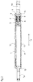
Fig. 2 is a cross-sectional structural view of the aforementioned first example. -
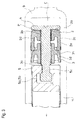
Fig. 3 is an enlarged cross-sectional structural view of essential parts of the first example, and shows a state when a piston moves forward. -
Fig. 4 is an enlarged cross-sectional structural view of the essential parts of the first example, and shows a state when the piston moves forward. -
Fig. 5 is an enlarged cross-sectional structural view of the essential parts of the first example, and shows a state when the piston moves backward. -
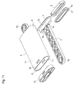
Fig. 6 is an exploded perspective view of the first example. -
Fig. 7 is a perspective view of a head part forming the piston of the first example. -
Fig. 8 is a perspective view of the piston of the first example. -
Fig. 9 is a perspective view of the piston of the first example, and shows such piston viewed from a right side inFig. 8 . -
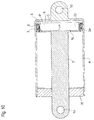
Fig. 10 is a cross-sectional view of the damper (a second example) according to another embodiment of the present invention. -
Fig. 11 is an exploded perspective view of the aforementioned second example. -
Fig. 12 is a perspective view of parts forming the piston of the second example. -
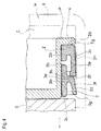
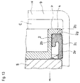
Fig. 13 is an enlarged cross-sectional structural view of the essential parts of the damper (a third example) according to another embodiment of the present invention, and shows a state when the piston moves forward. -
Fig. 14 is an enlarged cross-sectional structural view of the essential parts of the third example, and shows a state when the piston moves backward. - Hereinafter, based on
Fig. 1 to Fig. 14 , typical embodiments of the present invention will be explained. A damper according to the embodiments generates a braking force for an operation of a piston P forming the damper, i.e. a movement or a relative movement of such piston P. Typically, the damper is combined with an article provided with a movable portion or the like (omitted in the drawings) which becomes an object to be braked, and used for applying the braking force relative to a movement of such object so as to move such object slowly and properly, with a feeling of a high quality, or prevent such braking object from moving extraordinarily. - Such damper comprises the piston P provided with a
rod 1; and a housing H storing the piston P. Typically, such damper directly or indirectly links either one of therod 1 or the housing H on the aforementioned braking object side, and directly or indirectly links the other of therod 1 or the housing H on a side movably supporting such braking object so as to be combined with the article provided with such braking object. - The aforementioned housing H has a cylindrical shape opening one end and closing the other end. In illustrated examples, such housing H has a flat cylindrical shape wherein a thickness thereof is made notably small. More specifically, in the illustrated examples, in such housing H, a cross section orthogonal to a cylinder shaft thereof has substantially a rectangular shape.
Side walls 8 forming a thickness side of the housing H have a shape with a curvature wherein the outside of the housing H becomes the outside of the curvature. Outside a blockingend 9 of the housing H, there is formed abracket portion 10 for the aforementioned linking. - The
aforementioned rod 1 has a long rod shape in a moving direction of the piston P. On one end positioned outside the housing H in therod 1, there is formed abracket portion 1a for the aforementioned linking. - The aforementioned piston P is provided with a
seal member 2 relative to an inner wall of the housing H; and aslider 3 provided slidably relative to the piston P, and contacting the inner wall of the housing H with a predetermined frictional force. - In the illustrated examples, the piston P is provided with a
first flange 4 facing the blockingend 9 of the housing H; and asecond flange 5 retaining theseal member 2 and theslider 3 between thesecond flange 5 and thefirst flange 4. Thesecond flange 5 is positioned at a back side of thefirst flange 4, i.e. on anopen end 12 side of the housing H. In both thefirst flange 4 and thesecond flange 5, an outer frame shape in a cross section in a moving direction x (seeFig. 2 ) of the piston P, i.e. in a direction orthogonally in a direction along the cylinder shaft of the housing H, has a shape which becomes a complementary shape to an inner frame shape in the cross section of the housing H in the same direction. Thereby, the piston P is guided by the inner wall of the housing H so as to reciprocate in the direction along the cylinder shaft of the housing H. - In the first example shown in
Fig. 1 to Fig. 9 , thesecond flange 5 is formed in the other end of therod 1. Thefirst flange 4 is formed in ahead part 6 which is a separate member from the rod 1 (seeFigs. 6 and7 ) . Thehead part 6 includes a plate-like trunk portion 6a facing a plate face to the side walls on a width side of the housing H. On a side facing the blockingend 9 of the housing H in the trunk portion 6a, there is integrally formed thefirst flange 4 positioning a flange end outwardly more than an outer face of the trunk portion 6a at each position around the trunk portion 6a. Also, in a portion which is an end portion facing theopen end 12 of the housing H in the trunk portion 6a, and positioned on the cylinder shaft of such housing H, there is formed amale joint portion 6b formed by ahead portion 6c and aneck portion 6d, and integrated with the trunk portion 6a through theneck portion 6d. In a portion positioned on the cylinder shaft of the housing H in thesecond flange 5, there are formed afemale joint portion 5a formed by a firstconcave portion 5b receiving and retaining thehead portion 6c of themale joint portion 6b; and a secondconcave portion 5c receiving and retaining theneck portion 6c of themale joint portion 6b, and opening outwardly at an end portion facing the blockingend 9 of the housing H in the second flange 5 (seeFig. 6 ). In the first example, from a state wherein theseal member 2 and theslider 3 respectively having a flat ring shape are combined with thehead part 6 in such a way as to surround the trunk portion 6a of thehead part 6, themale joint portion 6b of thehead part 6 is fitted into thefemale joint portion 5a of thesecond flange 5 so as to form the piston P formed by retaining theseal member 2 and theslider 3 between suchfirst flange 4 andsecond flange 5. Incidentally, thereference symbol 6e shown inFig. 5 represents a cut-out portion inside thehead part 6. - Typically, the
seal member 2 is formed by rubber or plastic having a rubber-like elasticity, and has the flat ring shape. The truck portion 6a of thehead part 6 is inserted to pass through the inside of theseal member 2 from a side of the malejoint portion 6b so thatsuch head part 6 and sealmember 2 are combined. In the illustrated examples, theseal member 2 includes afront end face 2a relative to thefirst flange 4; aninner face 2b relative to an outer face of thehead part 6; and anouter face 2c relative to the inner wall of the housing H (seeFig. 3 ). Also, on a side facing theopen end 12 side of the housing H in theseal member 2, there is formed acircumferential groove 2d between theinner face 2b and theouter face 2c. An outer face side sandwiching thecircumferential groove 2d extends toward theopen end 12 side of the housing H throughout all circumferential directions of theseal member 2, so that theseal member 2 is provided with a skirt-shapedportion 2e, and theouter face 2c of theseal member 2 increases a size more than theinner face 2b in the moving direction x of the piston P. Theouter face 2c of theseal member 2 inclines in a direction of gradually increasing a thickness of theseal member 2 as moving from thefront end face 2a to a terminal 2f of the skirt-shapedportion 2e (seeFig. 4 ). Also, on thefront end face 2a of theseal member 2, there is formed acircumferential projection piece 2g. - Typically, the
slider 3 is formed by the plastic, and has the flat ring shape. As mentioned above, from a state wherein thehead part 6 and theseal member 2 are combined, the trunk portion 6a of thehead part 6 is inserted to pass through the inside of theslider 3 from the side of the malejoint portion 6b, so thatsuch head part 6 andslider 3 are combined. In the illustrated examples, theslider 3 is provided with a shortcylindrical base 3a wherein an inner frame shape in a cross section orthogonally in the moving direction x of the piston P has a shape which becomes complementary to an outer frame shape in a cross section of the trunk portion 6a of thehead part 6 in the same direction; and alip 3d integrally formed outside thebase 3a (seeFig. 3 ). In the illustrated examples, thelip 3d has a circumferential fin-like member formed in such a way as to surround thebase 3a. Thelip 3d has abase portion 3e integrated with an outer face portion of thebase 3a between afront end 3b positioned on aseal member 2 side and a back end 3c positioned on theopen end 12 side of the housing H in thebase 3a, and is provided with anextension portion 3f extending toward theopen end 12 side of the housing H from thebase portion 3e (seeFig. 4 ). Ashoulder portion 3h is formed between thebase portion 3e and theextension portion 3f. Theextension portion 3f has inclination gradually increasing a distance between theextension portion 3f and thebase 3a as moving to a terminal 3g thereof from theshoulder portion 3h. - The
seal member 2 and theslider 3 are held between thefirst flange 4 and thesecond flange 5 in a state allowing a slight movement along the moving direction x of the piston P. Theouter face 2c of theseal member 2 contacts the inner wall of the housing H throughout a whole circumference thereof, and theextension portion 3f of theslider 3 contacts the inner wall of the housing H on a terminal 3g side thereof throughout a whole circumference thereof as well. Also, a portion located between thefront end 3b of thebase 3a of theslider 3 and thebase portion 3e of thelip 3d is positioned inside the skirt-shapedportion 2e of theseal member 2, and theshoulder portion 3h of thelip 3d of theslider 3 faces the terminal 2f of the skirt-shapedportion 2e of the seal member 2 (Fig. 2 to Fig. 5 ). - Then, in the present embodiments, when the braking force is generated, the
slider 3 presses theseal member 2, and a portion contacting the inner wall of the housing H in theseal member 2 deforms outwardly toward the housing H. - In the illustrated examples, when the piston P moves forward in a direction of separating from the blocking
end 9 of the housing H, a chamber C formed between the piston P and the blockingend 9 comes to have a negative pressure, thereby generating a resistance due to a pressure change which becomes one portion of the braking force (Fig. 3 andFig. 4 ). Also, at that time, theslider 3 deforms theseal member 2 as mentioned above to increase a frictional force between theseal member 2 and the housing H, thereby generating a frictional resistance which becomes one portion of the braking force (Fig. 3 andFig. 4 ). - In the illustrated examples, when the piston P moves forward, the
slider 3 becomes difficult to move in the forward-moving direction due to a shape of thelip 3d, so that theshoulder portion 3h of theslider 3 is pressed against the terminal 2f of the skirt-shapedportion 2e of theseal member 2, and thecircumferential projection piece 2g formed in thefront end face 2a of theseal member 2 is firmly attached to thefirst flange 4 so as to seal between thefront end face 2a and thefirst flange 4, and the skirt-shapedportion 2e deforms outwardly so as to seal between theouter face 2c of theseal member 2 and the inner wall of the housing H (Fig. 3 andFig. 4 ). Thereby, in the illustrated examples, when the piston P moves forward, ventilation relative to the chamber C is limited to a vent passage formed by a groove 7 (seeFig. 6 to Fig. 8 ) formed throughout the end portion facing theopen end 12 of the housing H in the trunk portion 6a from an edge portion of thefirst flange 4 in a portion positioned on the cylinder shaft of the housing H in thehead part 6 forming the piston P so as to generate the resistance due to the aforementioned pressure change. Also, the skirt-shapedportion 2e of theseal member 2 deforms outwardly as described above so as to generate the aforementioned frictional resistance. Namely, theslider 3 is provided with a pressure contact portion pressed against theseal member 2 from therod 1 side, and in the illustrated examples, theshoulder portion 3h functions as the pressure contact portion. - In the present embodiments, in accordance with an operation speed of the piston P, a deformation amount of the
seal member 2 increases. From another point of view, in accordance with the operation speed of the piston P, a sliding amount of theslider 3 increases. Therefore, the damper according to the embodiments is a damper with a speed response type changing the braking force in accordance with a moving speed of the braking object which becomes the braking object, or a load response type. - When all or most of the braking force is covered by the resistance due to the aforementioned pressure change, the braking force is small at the time of starting the piston operation, and when the operation of the piston advances, the braking force rapidly increases. Consequently, in such a method, in some cases, there may be caused situations wherein the braking object halts in a moving process, and moreover, starts to unexpectedly move backward toward a position before the movement from a middle of the movement so as to be difficult to properly control the movement of the aforementioned braking object in a whole process thereof.
- On the other hand, in the damper according to the embodiments, the braking force is covered by the resistance due to the pressure change and the frictional resistance so as to properly control the movement of the braking object in the whole process thereof. Namely, the damper according to the embodiments can prevent the situations wherein the braking object halts in a forward moving process, and moreover, starts to unexpectedly move backward toward the position before the forward movement from a middle of the forward movement as much as possible. Also, the damper according to the embodiments can easily generate an intended braking force even if a cross-sectional area of the housing H is made small so as to have a characteristic which can easily reduce a size and thickness.
- On the other hand, in the illustrated examples, when the piston P moves backward in a direction of approaching the blocking
end 9 of the housing H, the chamber C is difficult to have a positive pressure, and at that time, the aforementioned frictional resistance becomes small as well (Fig. 5 ). In the illustrated examples, when the piston P moves backward, theseal member 2 and theslider 3 move to asecond flange 5 side to form a gap y between thefirst flange 4 and thefront end face 2a of theseal member 2, and due to the shape of thelip 3d, theslider 3 can easily move in a backward-moving direction of the piston P, so that theslider 3 is not pressed against theseal member 2, and the frictional resistance between theseal member 2 and the inner wall of the housing H does not increase as well. In addition to the vent passage formed by thegroove 7, the chamber C is communicated through the gap y between thefirst flange 4 and thefront end face 2a of theseal member 2 as well. Also, in the illustrated examples, on the outer face of theseal member 2, there is formed agroove 2h along the moving direction x of the piston P, and thegroove 2h opens a groove end on a chamber C side, and closes a groove end on theopen end 12 side of the housing H; however, when the piston P moves backward, due to a pressure increase on the chamber C side, at a position forming thegroove 2h, one portion of theseal member 2 deforms inwardly, and exhaust ventilation can be carried out from the chamber C through thegroove 2h as well. Thereby, in the illustrated examples, when the piston P moves backward, the damper is made so as not to generate a special braking force. Also, since the vent passage of the chamber C is expanded simultaneously when the piston P starts to move backward so as to prevent a situation wherein the braking object moves backward toward the position before the forward movement from the middle of the forward movement. - In the damper of a second example shown in
Fig. 10 to Fig. 12 , thicknesses of the housing H and piston P are increased compared to the damper of the first example. Thereference numeral 13 in the drawings represents a head corresponding to thehead part 6 of the first example, and the head is integrated with therod 1. The reference numeral 14 in the drawings represents claw portions functioning in the same manner as in thesecond flange 5 of the first example, and thereference numeral 15 represents a cap closing theopen end 12 of the housing H. Also, in the damper of the second example, the vent passage always communicating the chamber C with the outside becomes anorifice 16 penetrating the head. The rest of the structural parts of the damper of the second example are substantially the same as those of the damper of the first example, so that regarding the same structural parts, symbols same as those used inFig. 1 to Fig. 9 showing the damper of the first example are assigned toFig. 10 to Fig. 12 showing the damper of the second example, and their explanations are omitted. - The damper of a third example shown in
Fig. 13 andFig. 14 has a structure that the piston P is not provided with theslider 3. The rest of the structures of the damper of the third example are substantially the same as those of the damper of the first example so as to omit their explanations. Then, in the damper of the third example, the portion contacting the inner wall of the housing H in theseal member 2 deforms outwardly toward the housing H when the chamber C formed between the piston P and the blockingend 9 of the housing H has the negative pressure (Fig. 13 ). Namely, in the third example, when the piston P moves forward, thecircumferential projection piece 2g formed on thefront end face 2a of theseal member 2 is firmly attached to thefirst flange 4 so as to seal between thefront end face 2a and thefirst flange 4, and since the inside of the chamber C has the negative pressure, due to a force applied to the skirt-shapedportion 2e and shown with the reference alphabet F inFig. 13 , the skirt-shapedportion 2e deforms outwardly to seal between theouter face 2c of theseal member 2 and the inner wall of the housing H (Fig. 13 ). Thereby, in the third example, when the piston P moves forward, the resistance due to the pressure change is generated. Also, the skirt-shapedportion 2e of theseal member 2 deforms outwardly so as to generate the frictional resistance. Even in the damper of the third example, in accordance with the operation speed of the piston P, the deformation amount of theseal member 2 increases. - All of each damper device explained above can easily generate the intended braking force even if the cross-sectional area of the housing H is made small as described above so as to have the flat and thin outer frame shape in the cross section of the housing in the direction orthogonally in the moving direction of the piston.
- Incidentally, obviously, the present invention is not limited to the embodiments explained above, and the embodiments include all embodiments which can obtain the object of the present invention.
- All contents of the specification, claims, drawings, and abstract of Japanese Patent Application No.
2013-262149 filed on December 19, 2013
Claims (8)
- A damper comprising a piston provided with a rod, and a housing storing the piston, and generating a braking force by an operation of the piston,
wherein the piston includes a seal member relative to an inner wall of the housing, and a slider provided slidably relative to the piston, and contacting the inner wall of the housing with a predetermined frictional force, and
when the braking force is generated, the slider presses against the seal member, so that a portion contacting the inner wall of the housing in the seal member deforms outwardly toward the housing. - A damper according to claim 1, wherein the slider contacts the inner wall of the housing with a lip.
- A damper according to claim 1 or 2, wherein the slider includes a pressure contact portion pressed against the seal member from a rod side.
- A damper according to any one of claims 1 to 3, wherein in accordance with an operation speed of the piston, a deformation amount of the seal member increases.
- A damper according to any one of claims 1 to 3, wherein in accordance with an operation speed of the piston, a sliding amount of the slider increases.
- A damper, comprising a piston provided with a rod, and a housing storing the piston, and generating a braking force by an operation force of the piston,
wherein the piston includes a seal member relative to an inner wall of the housing, and
a portion contacting the inner wall of the housing in the seal member deforms outwardly toward the housing when a chamber formed between the piston and a blocking end of the housing has a negative pressure. - A damper according to claim 6, wherein in accordance with an operation speed of the piston, a deformation amount of the seal member increases.
- A damper according to any one of claims 1 to 7, wherein an outer frame shape in a cross section of the housing in a direction orthogonal to a moving direction of the piston is made flat.
Applications Claiming Priority (2)
| Application Number | Priority Date | Filing Date | Title |
|---|---|---|---|
| JP2013262149 | 2013-12-19 | ||
| PCT/JP2014/083468 WO2015093548A1 (en) | 2013-12-19 | 2014-12-17 | Damper |
Publications (3)
| Publication Number | Publication Date |
|---|---|
| EP3085987A1 true EP3085987A1 (en) | 2016-10-26 |
| EP3085987A4 EP3085987A4 (en) | 2017-10-11 |
| EP3085987B1 EP3085987B1 (en) | 2019-11-20 |
Family
ID=53402892
Family Applications (1)
| Application Number | Title | Priority Date | Filing Date |
|---|---|---|---|
| EP14870932.2A Active EP3085987B1 (en) | 2013-12-19 | 2014-12-17 | Damper |
Country Status (6)
| Country | Link |
|---|---|
| US (1) | US9850975B2 (en) |
| EP (1) | EP3085987B1 (en) |
| JP (1) | JP6138278B2 (en) |
| KR (1) | KR101647562B1 (en) |
| CN (1) | CN105829758B (en) |
| WO (1) | WO2015093548A1 (en) |
Families Citing this family (10)
| Publication number | Priority date | Publication date | Assignee | Title |
|---|---|---|---|---|
| JP6393234B2 (en) * | 2015-05-15 | 2018-09-19 | 株式会社ニフコ | Damper |
| KR101867172B1 (en) * | 2015-09-18 | 2018-06-12 | 가부시키가이샤 니프코 | Damper |
| DK179577B1 (en) | 2016-10-10 | 2019-02-20 | Widex A/S | Binaural hearing aid system and a method of operating a binaural hearing aid system |
| JP6576321B2 (en) * | 2016-10-26 | 2019-09-18 | 株式会社ニフコ | Damper |
| WO2018190256A1 (en) * | 2017-04-12 | 2018-10-18 | 株式会社パイオラックス | Damper |
| CN108223661B (en) * | 2018-01-16 | 2018-12-11 | 罗茜 | A kind of deformation damper |
| CN108374859B (en) * | 2018-02-08 | 2020-11-17 | 江苏三尔汽车部件有限公司 | Shock absorber |
| JP6992165B2 (en) * | 2018-03-28 | 2022-01-17 | 株式会社パイオラックス | Damper |
| JP7449885B2 (en) * | 2021-02-15 | 2024-03-14 | 株式会社ニフコ | damper device |
| DE102022202661A1 (en) * | 2022-03-17 | 2023-09-21 | Suspa Gmbh | Dampers, especially friction dampers |
Family Cites Families (19)
| Publication number | Priority date | Publication date | Assignee | Title |
|---|---|---|---|---|
| US4110868A (en) * | 1976-02-23 | 1978-09-05 | Yasutaka Imazaike | Air damper |
| US5070971A (en) * | 1990-04-23 | 1991-12-10 | General Motors Corporation | Molded piston for a hydraulic damper |
| JP3397923B2 (en) * | 1995-01-25 | 2003-04-21 | エヌオーケー株式会社 | Sealing device |
| DE19717937A1 (en) * | 1996-11-08 | 1998-05-20 | Grass Ag | Braking and damping element for moving furniture parts |
| US6062352A (en) * | 1998-08-24 | 2000-05-16 | Piolax, Inc. | Air damper |
| JP3298002B2 (en) | 1998-09-10 | 2002-07-02 | 株式会社パイオラックス | Air damper |
| DE20122569U1 (en) | 2001-01-09 | 2006-04-27 | Julius Blum Gmbh | Pneumatic braking and damping device for movable parts of furniture e.g. drawer, includes elastically deformable sealing ring between linearly displaceable pistons |
| AT414033B (en) | 2001-01-09 | 2006-08-15 | Blum Gmbh Julius | DAMPERS, ESPECIALLY FOR FURNITURE |
| JP4517858B2 (en) * | 2003-01-30 | 2010-08-04 | ジュリウス ブルム ゲゼルシャフト エム.ビー.エイチ. | Damper for movable furniture parts |
| DE10313659B3 (en) * | 2003-03-26 | 2004-09-30 | Zimmer, Günther Stephan | Pneumatic retarding device for braking movable furniture parts |
| DE202004009535U1 (en) * | 2004-06-16 | 2005-11-10 | Alfit Ag | Device for damping or deceleration of moving furniture parts of furniture |
| EP1662170B1 (en) * | 2004-11-26 | 2008-06-25 | Christian Krischke-Lengersdorf | Pneumatic damper |
| DE102004057561A1 (en) | 2004-11-30 | 2007-04-19 | Bruno Meier | Pneumatic deceleration device for braking movable furniture parts, in particular drawers |
| JP4778819B2 (en) * | 2006-03-27 | 2011-09-21 | 株式会社ニフコ | Speed response type air damper |
| DE102006040085A1 (en) * | 2006-08-28 | 2008-03-20 | Zimmer, Günther | Cost-effective to produce pneumatic retarding device |
| JP4929495B2 (en) * | 2006-12-06 | 2012-05-09 | Smc株式会社 | Damper fixing structure |
| DE102008010908B4 (en) * | 2008-02-25 | 2015-05-28 | Günther Zimmer | Piston sealing element and retarding device with piston sealing element |
| US20120091641A1 (en) * | 2010-10-19 | 2012-04-19 | Ching-Chuan Yang | Air pressure buffer |
| US20120175830A1 (en) * | 2011-01-07 | 2012-07-12 | Ching-Chuan Yang | Buffer |
-
2014
- 2014-12-03 KR KR1020140172266A patent/KR101647562B1/en active Active
- 2014-12-17 US US15/105,989 patent/US9850975B2/en active Active
- 2014-12-17 WO PCT/JP2014/083468 patent/WO2015093548A1/en not_active Ceased
- 2014-12-17 CN CN201480068816.6A patent/CN105829758B/en active Active
- 2014-12-17 JP JP2015553593A patent/JP6138278B2/en active Active
- 2014-12-17 EP EP14870932.2A patent/EP3085987B1/en active Active
Also Published As
| Publication number | Publication date |
|---|---|
| JPWO2015093548A1 (en) | 2017-03-23 |
| KR101647562B1 (en) | 2016-08-10 |
| CN105829758B (en) | 2017-10-31 |
| EP3085987A4 (en) | 2017-10-11 |
| WO2015093548A1 (en) | 2015-06-25 |
| CN105829758A (en) | 2016-08-03 |
| KR20150072335A (en) | 2015-06-29 |
| US9850975B2 (en) | 2017-12-26 |
| JP6138278B2 (en) | 2017-05-31 |
| EP3085987B1 (en) | 2019-11-20 |
| US20170002886A1 (en) | 2017-01-05 |
Similar Documents
| Publication | Publication Date | Title |
|---|---|---|
| EP3085987B1 (en) | Damper | |
| US10883557B2 (en) | Damper | |
| US8453810B2 (en) | Damper device | |
| EP3296588B1 (en) | Damper | |
| EP3351820B1 (en) | Damper | |
| KR101698735B1 (en) | Valve stem seal | |
| JP5959164B2 (en) | Damper device | |
| JP6479234B2 (en) | Damper | |
| CN116848335A (en) | damping device | |
| US10173656B2 (en) | Negative pressure type booster device | |
| KR20140059664A (en) | Brake booster | |
| JP2017171234A (en) | Cylinder device |
Legal Events
| Date | Code | Title | Description |
|---|---|---|---|
| PUAI | Public reference made under article 153(3) epc to a published international application that has entered the european phase |
Free format text: ORIGINAL CODE: 0009012 |
|
| 17P | Request for examination filed |
Effective date: 20160623 |
|
| AK | Designated contracting states |
Kind code of ref document: A1 Designated state(s): AL AT BE BG CH CY CZ DE DK EE ES FI FR GB GR HR HU IE IS IT LI LT LU LV MC MK MT NL NO PL PT RO RS SE SI SK SM TR |
|
| AX | Request for extension of the european patent |
Extension state: BA ME |
|
| DAX | Request for extension of the european patent (deleted) | ||
| REG | Reference to a national code |
Ref country code: DE Ref legal event code: R079 Ref document number: 602014057299 Country of ref document: DE Free format text: PREVIOUS MAIN CLASS: F16F0009020000 Ipc: F16F0009512000 |
|
| A4 | Supplementary search report drawn up and despatched |
Effective date: 20170908 |
|
| RIC1 | Information provided on ipc code assigned before grant |
Ipc: F16F 7/09 20060101ALI20170904BHEP Ipc: F16F 9/02 20060101ALI20170904BHEP Ipc: F16F 9/36 20060101ALI20170904BHEP Ipc: F16F 9/32 20060101ALI20170904BHEP Ipc: F16F 9/512 20060101AFI20170904BHEP |
|
| STAA | Information on the status of an ep patent application or granted ep patent |
Free format text: STATUS: EXAMINATION IS IN PROGRESS |
|
| 17Q | First examination report despatched |
Effective date: 20180503 |
|
| GRAP | Despatch of communication of intention to grant a patent |
Free format text: ORIGINAL CODE: EPIDOSNIGR1 |
|
| STAA | Information on the status of an ep patent application or granted ep patent |
Free format text: STATUS: GRANT OF PATENT IS INTENDED |
|
| INTG | Intention to grant announced |
Effective date: 20190808 |
|
| GRAS | Grant fee paid |
Free format text: ORIGINAL CODE: EPIDOSNIGR3 |
|
| GRAA | (expected) grant |
Free format text: ORIGINAL CODE: 0009210 |
|
| STAA | Information on the status of an ep patent application or granted ep patent |
Free format text: STATUS: THE PATENT HAS BEEN GRANTED |
|
| AK | Designated contracting states |
Kind code of ref document: B1 Designated state(s): AL AT BE BG CH CY CZ DE DK EE ES FI FR GB GR HR HU IE IS IT LI LT LU LV MC MK MT NL NO PL PT RO RS SE SI SK SM TR |
|
| REG | Reference to a national code |
Ref country code: GB Ref legal event code: FG4D |
|
| REG | Reference to a national code |
Ref country code: CH Ref legal event code: EP |
|
| REG | Reference to a national code |
Ref country code: IE Ref legal event code: FG4D |
|
| REG | Reference to a national code |
Ref country code: DE Ref legal event code: R096 Ref document number: 602014057299 Country of ref document: DE |
|
| REG | Reference to a national code |
Ref country code: AT Ref legal event code: REF Ref document number: 1204534 Country of ref document: AT Kind code of ref document: T Effective date: 20191215 |
|
| REG | Reference to a national code |
Ref country code: NL Ref legal event code: MP Effective date: 20191120 |
|
| REG | Reference to a national code |
Ref country code: LT Ref legal event code: MG4D |
|
| PG25 | Lapsed in a contracting state [announced via postgrant information from national office to epo] |
Ref country code: LT Free format text: LAPSE BECAUSE OF FAILURE TO SUBMIT A TRANSLATION OF THE DESCRIPTION OR TO PAY THE FEE WITHIN THE PRESCRIBED TIME-LIMIT Effective date: 20191120 Ref country code: NO Free format text: LAPSE BECAUSE OF FAILURE TO SUBMIT A TRANSLATION OF THE DESCRIPTION OR TO PAY THE FEE WITHIN THE PRESCRIBED TIME-LIMIT Effective date: 20200220 Ref country code: GR Free format text: LAPSE BECAUSE OF FAILURE TO SUBMIT A TRANSLATION OF THE DESCRIPTION OR TO PAY THE FEE WITHIN THE PRESCRIBED TIME-LIMIT Effective date: 20200221 Ref country code: FI Free format text: LAPSE BECAUSE OF FAILURE TO SUBMIT A TRANSLATION OF THE DESCRIPTION OR TO PAY THE FEE WITHIN THE PRESCRIBED TIME-LIMIT Effective date: 20191120 Ref country code: BG Free format text: LAPSE BECAUSE OF FAILURE TO SUBMIT A TRANSLATION OF THE DESCRIPTION OR TO PAY THE FEE WITHIN THE PRESCRIBED TIME-LIMIT Effective date: 20200220 Ref country code: LV Free format text: LAPSE BECAUSE OF FAILURE TO SUBMIT A TRANSLATION OF THE DESCRIPTION OR TO PAY THE FEE WITHIN THE PRESCRIBED TIME-LIMIT Effective date: 20191120 Ref country code: SE Free format text: LAPSE BECAUSE OF FAILURE TO SUBMIT A TRANSLATION OF THE DESCRIPTION OR TO PAY THE FEE WITHIN THE PRESCRIBED TIME-LIMIT Effective date: 20191120 Ref country code: NL Free format text: LAPSE BECAUSE OF FAILURE TO SUBMIT A TRANSLATION OF THE DESCRIPTION OR TO PAY THE FEE WITHIN THE PRESCRIBED TIME-LIMIT Effective date: 20191120 |
|
| PG25 | Lapsed in a contracting state [announced via postgrant information from national office to epo] |
Ref country code: HR Free format text: LAPSE BECAUSE OF FAILURE TO SUBMIT A TRANSLATION OF THE DESCRIPTION OR TO PAY THE FEE WITHIN THE PRESCRIBED TIME-LIMIT Effective date: 20191120 Ref country code: IS Free format text: LAPSE BECAUSE OF FAILURE TO SUBMIT A TRANSLATION OF THE DESCRIPTION OR TO PAY THE FEE WITHIN THE PRESCRIBED TIME-LIMIT Effective date: 20200320 Ref country code: RS Free format text: LAPSE BECAUSE OF FAILURE TO SUBMIT A TRANSLATION OF THE DESCRIPTION OR TO PAY THE FEE WITHIN THE PRESCRIBED TIME-LIMIT Effective date: 20191120 |
|
| PG25 | Lapsed in a contracting state [announced via postgrant information from national office to epo] |
Ref country code: AL Free format text: LAPSE BECAUSE OF FAILURE TO SUBMIT A TRANSLATION OF THE DESCRIPTION OR TO PAY THE FEE WITHIN THE PRESCRIBED TIME-LIMIT Effective date: 20191120 |
|
| PG25 | Lapsed in a contracting state [announced via postgrant information from national office to epo] |
Ref country code: ES Free format text: LAPSE BECAUSE OF FAILURE TO SUBMIT A TRANSLATION OF THE DESCRIPTION OR TO PAY THE FEE WITHIN THE PRESCRIBED TIME-LIMIT Effective date: 20191120 Ref country code: CZ Free format text: LAPSE BECAUSE OF FAILURE TO SUBMIT A TRANSLATION OF THE DESCRIPTION OR TO PAY THE FEE WITHIN THE PRESCRIBED TIME-LIMIT Effective date: 20191120 Ref country code: RO Free format text: LAPSE BECAUSE OF FAILURE TO SUBMIT A TRANSLATION OF THE DESCRIPTION OR TO PAY THE FEE WITHIN THE PRESCRIBED TIME-LIMIT Effective date: 20191120 Ref country code: DK Free format text: LAPSE BECAUSE OF FAILURE TO SUBMIT A TRANSLATION OF THE DESCRIPTION OR TO PAY THE FEE WITHIN THE PRESCRIBED TIME-LIMIT Effective date: 20191120 Ref country code: EE Free format text: LAPSE BECAUSE OF FAILURE TO SUBMIT A TRANSLATION OF THE DESCRIPTION OR TO PAY THE FEE WITHIN THE PRESCRIBED TIME-LIMIT Effective date: 20191120 Ref country code: PT Free format text: LAPSE BECAUSE OF FAILURE TO SUBMIT A TRANSLATION OF THE DESCRIPTION OR TO PAY THE FEE WITHIN THE PRESCRIBED TIME-LIMIT Effective date: 20200412 |
|
| REG | Reference to a national code |
Ref country code: CH Ref legal event code: PL |
|
| REG | Reference to a national code |
Ref country code: AT Ref legal event code: MK05 Ref document number: 1204534 Country of ref document: AT Kind code of ref document: T Effective date: 20191120 |
|
| REG | Reference to a national code |
Ref country code: DE Ref legal event code: R097 Ref document number: 602014057299 Country of ref document: DE |
|
| REG | Reference to a national code |
Ref country code: BE Ref legal event code: MM Effective date: 20191231 |
|
| PG25 | Lapsed in a contracting state [announced via postgrant information from national office to epo] |
Ref country code: SM Free format text: LAPSE BECAUSE OF FAILURE TO SUBMIT A TRANSLATION OF THE DESCRIPTION OR TO PAY THE FEE WITHIN THE PRESCRIBED TIME-LIMIT Effective date: 20191120 Ref country code: SK Free format text: LAPSE BECAUSE OF FAILURE TO SUBMIT A TRANSLATION OF THE DESCRIPTION OR TO PAY THE FEE WITHIN THE PRESCRIBED TIME-LIMIT Effective date: 20191120 Ref country code: MC Free format text: LAPSE BECAUSE OF FAILURE TO SUBMIT A TRANSLATION OF THE DESCRIPTION OR TO PAY THE FEE WITHIN THE PRESCRIBED TIME-LIMIT Effective date: 20191120 |
|
| PLBE | No opposition filed within time limit |
Free format text: ORIGINAL CODE: 0009261 |
|
| STAA | Information on the status of an ep patent application or granted ep patent |
Free format text: STATUS: NO OPPOSITION FILED WITHIN TIME LIMIT |
|
| 26N | No opposition filed |
Effective date: 20200821 |
|
| PG25 | Lapsed in a contracting state [announced via postgrant information from national office to epo] |
Ref country code: IE Free format text: LAPSE BECAUSE OF NON-PAYMENT OF DUE FEES Effective date: 20191217 Ref country code: LU Free format text: LAPSE BECAUSE OF NON-PAYMENT OF DUE FEES Effective date: 20191217 |
|
| PG25 | Lapsed in a contracting state [announced via postgrant information from national office to epo] |
Ref country code: AT Free format text: LAPSE BECAUSE OF FAILURE TO SUBMIT A TRANSLATION OF THE DESCRIPTION OR TO PAY THE FEE WITHIN THE PRESCRIBED TIME-LIMIT Effective date: 20191120 Ref country code: LI Free format text: LAPSE BECAUSE OF NON-PAYMENT OF DUE FEES Effective date: 20191231 Ref country code: BE Free format text: LAPSE BECAUSE OF NON-PAYMENT OF DUE FEES Effective date: 20191231 Ref country code: CH Free format text: LAPSE BECAUSE OF NON-PAYMENT OF DUE FEES Effective date: 20191231 Ref country code: PL Free format text: LAPSE BECAUSE OF FAILURE TO SUBMIT A TRANSLATION OF THE DESCRIPTION OR TO PAY THE FEE WITHIN THE PRESCRIBED TIME-LIMIT Effective date: 20191120 Ref country code: SI Free format text: LAPSE BECAUSE OF FAILURE TO SUBMIT A TRANSLATION OF THE DESCRIPTION OR TO PAY THE FEE WITHIN THE PRESCRIBED TIME-LIMIT Effective date: 20191120 |
|
| PG25 | Lapsed in a contracting state [announced via postgrant information from national office to epo] |
Ref country code: IT Free format text: LAPSE BECAUSE OF FAILURE TO SUBMIT A TRANSLATION OF THE DESCRIPTION OR TO PAY THE FEE WITHIN THE PRESCRIBED TIME-LIMIT Effective date: 20191120 |
|
| PGFP | Annual fee paid to national office [announced via postgrant information from national office to epo] |
Ref country code: DE Payment date: 20201201 Year of fee payment: 7 |
|
| PG25 | Lapsed in a contracting state [announced via postgrant information from national office to epo] |
Ref country code: CY Free format text: LAPSE BECAUSE OF FAILURE TO SUBMIT A TRANSLATION OF THE DESCRIPTION OR TO PAY THE FEE WITHIN THE PRESCRIBED TIME-LIMIT Effective date: 20191120 |
|
| PG25 | Lapsed in a contracting state [announced via postgrant information from national office to epo] |
Ref country code: MT Free format text: LAPSE BECAUSE OF FAILURE TO SUBMIT A TRANSLATION OF THE DESCRIPTION OR TO PAY THE FEE WITHIN THE PRESCRIBED TIME-LIMIT Effective date: 20191120 Ref country code: HU Free format text: LAPSE BECAUSE OF FAILURE TO SUBMIT A TRANSLATION OF THE DESCRIPTION OR TO PAY THE FEE WITHIN THE PRESCRIBED TIME-LIMIT; INVALID AB INITIO Effective date: 20141217 |
|
| PG25 | Lapsed in a contracting state [announced via postgrant information from national office to epo] |
Ref country code: TR Free format text: LAPSE BECAUSE OF FAILURE TO SUBMIT A TRANSLATION OF THE DESCRIPTION OR TO PAY THE FEE WITHIN THE PRESCRIBED TIME-LIMIT Effective date: 20191120 |
|
| PG25 | Lapsed in a contracting state [announced via postgrant information from national office to epo] |
Ref country code: MK Free format text: LAPSE BECAUSE OF FAILURE TO SUBMIT A TRANSLATION OF THE DESCRIPTION OR TO PAY THE FEE WITHIN THE PRESCRIBED TIME-LIMIT Effective date: 20191120 |
|
| REG | Reference to a national code |
Ref country code: DE Ref legal event code: R119 Ref document number: 602014057299 Country of ref document: DE |
|
| PG25 | Lapsed in a contracting state [announced via postgrant information from national office to epo] |
Ref country code: DE Free format text: LAPSE BECAUSE OF NON-PAYMENT OF DUE FEES Effective date: 20220701 |
|
| PGFP | Annual fee paid to national office [announced via postgrant information from national office to epo] |
Ref country code: GB Payment date: 20251030 Year of fee payment: 12 |
|
| PGFP | Annual fee paid to national office [announced via postgrant information from national office to epo] |
Ref country code: FR Payment date: 20251110 Year of fee payment: 12 |