EP3085975A1 - Member drive mechanism - Google Patents
Member drive mechanism Download PDFInfo
- Publication number
- EP3085975A1 EP3085975A1 EP14872534.4A EP14872534A EP3085975A1 EP 3085975 A1 EP3085975 A1 EP 3085975A1 EP 14872534 A EP14872534 A EP 14872534A EP 3085975 A1 EP3085975 A1 EP 3085975A1
- Authority
- EP
- European Patent Office
- Prior art keywords
- section
- screw
- abutting
- urging
- component
- Prior art date
- Legal status (The legal status is an assumption and is not a legal conclusion. Google has not performed a legal analysis and makes no representation as to the accuracy of the status listed.)
- Granted
Links
- 230000007246 mechanism Effects 0.000 title claims abstract description 66
- 230000008859 change Effects 0.000 claims abstract description 9
- 230000008878 coupling Effects 0.000 claims description 10
- 238000010168 coupling process Methods 0.000 claims description 10
- 238000005859 coupling reaction Methods 0.000 claims description 10
- 238000009825 accumulation Methods 0.000 abstract description 13
- 238000012423 maintenance Methods 0.000 abstract 1
- 238000013016 damping Methods 0.000 description 47
- 230000004048 modification Effects 0.000 description 27
- 238000012986 modification Methods 0.000 description 27
- 238000003780 insertion Methods 0.000 description 10
- 230000037431 insertion Effects 0.000 description 10
- 239000011347 resin Substances 0.000 description 10
- 229920005989 resin Polymers 0.000 description 10
- 238000010586 diagram Methods 0.000 description 8
- 210000000078 claw Anatomy 0.000 description 6
- 238000000034 method Methods 0.000 description 5
- 238000003825 pressing Methods 0.000 description 5
- 230000008569 process Effects 0.000 description 5
- 238000013459 approach Methods 0.000 description 3
- 238000006073 displacement reaction Methods 0.000 description 3
- 230000005489 elastic deformation Effects 0.000 description 3
- 230000009471 action Effects 0.000 description 2
- 230000001154 acute effect Effects 0.000 description 2
- 238000005422 blasting Methods 0.000 description 2
- 230000007423 decrease Effects 0.000 description 2
- 230000002401 inhibitory effect Effects 0.000 description 2
- 239000000463 material Substances 0.000 description 2
- 230000007704 transition Effects 0.000 description 2
- 241001076388 Fimbria Species 0.000 description 1
- 239000004677 Nylon Substances 0.000 description 1
- 238000005520 cutting process Methods 0.000 description 1
- 238000005034 decoration Methods 0.000 description 1
- 230000000694 effects Effects 0.000 description 1
- 239000012530 fluid Substances 0.000 description 1
- 230000001788 irregular Effects 0.000 description 1
- 238000005304 joining Methods 0.000 description 1
- 239000002184 metal Substances 0.000 description 1
- 238000000465 moulding Methods 0.000 description 1
- 229920001778 nylon Polymers 0.000 description 1
- 230000002441 reversible effect Effects 0.000 description 1
- 230000000630 rising effect Effects 0.000 description 1
- 238000007493 shaping process Methods 0.000 description 1
- 238000009423 ventilation Methods 0.000 description 1
- 238000005406 washing Methods 0.000 description 1
Images


Classifications
-
- F—MECHANICAL ENGINEERING; LIGHTING; HEATING; WEAPONS; BLASTING
- F16—ENGINEERING ELEMENTS AND UNITS; GENERAL MEASURES FOR PRODUCING AND MAINTAINING EFFECTIVE FUNCTIONING OF MACHINES OR INSTALLATIONS; THERMAL INSULATION IN GENERAL
- F16B—DEVICES FOR FASTENING OR SECURING CONSTRUCTIONAL ELEMENTS OR MACHINE PARTS TOGETHER, e.g. NAILS, BOLTS, CIRCLIPS, CLAMPS, CLIPS OR WEDGES; JOINTS OR JOINTING
- F16B5/00—Joining sheets or plates, e.g. panels, to one another or to strips or bars parallel to them
- F16B5/02—Joining sheets or plates, e.g. panels, to one another or to strips or bars parallel to them by means of fastening members using screw-thread
- F16B5/0241—Joining sheets or plates, e.g. panels, to one another or to strips or bars parallel to them by means of fastening members using screw-thread with the possibility for the connection to absorb deformation, e.g. thermal or vibrational
-
- F—MECHANICAL ENGINEERING; LIGHTING; HEATING; WEAPONS; BLASTING
- F02—COMBUSTION ENGINES; HOT-GAS OR COMBUSTION-PRODUCT ENGINE PLANTS
- F02F—CYLINDERS, PISTONS OR CASINGS, FOR COMBUSTION ENGINES; ARRANGEMENTS OF SEALINGS IN COMBUSTION ENGINES
- F02F7/00—Casings, e.g. crankcases or frames
-
- F—MECHANICAL ENGINEERING; LIGHTING; HEATING; WEAPONS; BLASTING
- F16—ENGINEERING ELEMENTS AND UNITS; GENERAL MEASURES FOR PRODUCING AND MAINTAINING EFFECTIVE FUNCTIONING OF MACHINES OR INSTALLATIONS; THERMAL INSULATION IN GENERAL
- F16B—DEVICES FOR FASTENING OR SECURING CONSTRUCTIONAL ELEMENTS OR MACHINE PARTS TOGETHER, e.g. NAILS, BOLTS, CIRCLIPS, CLAMPS, CLIPS OR WEDGES; JOINTS OR JOINTING
- F16B19/00—Bolts without screw-thread; Pins, including deformable elements; Rivets
-
- F—MECHANICAL ENGINEERING; LIGHTING; HEATING; WEAPONS; BLASTING
- F16—ENGINEERING ELEMENTS AND UNITS; GENERAL MEASURES FOR PRODUCING AND MAINTAINING EFFECTIVE FUNCTIONING OF MACHINES OR INSTALLATIONS; THERMAL INSULATION IN GENERAL
- F16B—DEVICES FOR FASTENING OR SECURING CONSTRUCTIONAL ELEMENTS OR MACHINE PARTS TOGETHER, e.g. NAILS, BOLTS, CIRCLIPS, CLAMPS, CLIPS OR WEDGES; JOINTS OR JOINTING
- F16B21/00—Means for preventing relative axial movement of a pin, spigot, shaft or the like and a member surrounding it; Stud-and-socket releasable fastenings
- F16B21/06—Releasable fastening devices with snap-action
- F16B21/07—Releasable fastening devices with snap-action in which the socket has a resilient part
- F16B21/073—Releasable fastening devices with snap-action in which the socket has a resilient part the socket having a resilient part on its inside
-
- F—MECHANICAL ENGINEERING; LIGHTING; HEATING; WEAPONS; BLASTING
- F16—ENGINEERING ELEMENTS AND UNITS; GENERAL MEASURES FOR PRODUCING AND MAINTAINING EFFECTIVE FUNCTIONING OF MACHINES OR INSTALLATIONS; THERMAL INSULATION IN GENERAL
- F16B—DEVICES FOR FASTENING OR SECURING CONSTRUCTIONAL ELEMENTS OR MACHINE PARTS TOGETHER, e.g. NAILS, BOLTS, CIRCLIPS, CLAMPS, CLIPS OR WEDGES; JOINTS OR JOINTING
- F16B35/00—Screw-bolts; Stay-bolts; Screw-threaded studs; Screws; Set screws
- F16B35/04—Screw-bolts; Stay-bolts; Screw-threaded studs; Screws; Set screws with specially-shaped head or shaft in order to fix the bolt on or in an object
-
- F—MECHANICAL ENGINEERING; LIGHTING; HEATING; WEAPONS; BLASTING
- F16—ENGINEERING ELEMENTS AND UNITS; GENERAL MEASURES FOR PRODUCING AND MAINTAINING EFFECTIVE FUNCTIONING OF MACHINES OR INSTALLATIONS; THERMAL INSULATION IN GENERAL
- F16B—DEVICES FOR FASTENING OR SECURING CONSTRUCTIONAL ELEMENTS OR MACHINE PARTS TOGETHER, e.g. NAILS, BOLTS, CIRCLIPS, CLAMPS, CLIPS OR WEDGES; JOINTS OR JOINTING
- F16B37/00—Nuts or like thread-engaging members
- F16B37/08—Quickly-detachable or mountable nuts, e.g. consisting of two or more parts; Nuts movable along the bolt after tilting the nut
-
- F—MECHANICAL ENGINEERING; LIGHTING; HEATING; WEAPONS; BLASTING
- F16—ENGINEERING ELEMENTS AND UNITS; GENERAL MEASURES FOR PRODUCING AND MAINTAINING EFFECTIVE FUNCTIONING OF MACHINES OR INSTALLATIONS; THERMAL INSULATION IN GENERAL
- F16B—DEVICES FOR FASTENING OR SECURING CONSTRUCTIONAL ELEMENTS OR MACHINE PARTS TOGETHER, e.g. NAILS, BOLTS, CIRCLIPS, CLAMPS, CLIPS OR WEDGES; JOINTS OR JOINTING
- F16B39/00—Locking of screws, bolts or nuts
- F16B39/02—Locking of screws, bolts or nuts in which the locking takes place after screwing down
-
- F—MECHANICAL ENGINEERING; LIGHTING; HEATING; WEAPONS; BLASTING
- F16—ENGINEERING ELEMENTS AND UNITS; GENERAL MEASURES FOR PRODUCING AND MAINTAINING EFFECTIVE FUNCTIONING OF MACHINES OR INSTALLATIONS; THERMAL INSULATION IN GENERAL
- F16B—DEVICES FOR FASTENING OR SECURING CONSTRUCTIONAL ELEMENTS OR MACHINE PARTS TOGETHER, e.g. NAILS, BOLTS, CIRCLIPS, CLAMPS, CLIPS OR WEDGES; JOINTS OR JOINTING
- F16B5/00—Joining sheets or plates, e.g. panels, to one another or to strips or bars parallel to them
- F16B5/02—Joining sheets or plates, e.g. panels, to one another or to strips or bars parallel to them by means of fastening members using screw-thread
- F16B5/0258—Joining sheets or plates, e.g. panels, to one another or to strips or bars parallel to them by means of fastening members using screw-thread using resiliently deformable sleeves, grommets or inserts
-
- F—MECHANICAL ENGINEERING; LIGHTING; HEATING; WEAPONS; BLASTING
- F16—ENGINEERING ELEMENTS AND UNITS; GENERAL MEASURES FOR PRODUCING AND MAINTAINING EFFECTIVE FUNCTIONING OF MACHINES OR INSTALLATIONS; THERMAL INSULATION IN GENERAL
- F16F—SPRINGS; SHOCK-ABSORBERS; MEANS FOR DAMPING VIBRATION
- F16F7/00—Vibration-dampers; Shock-absorbers
-
- Y—GENERAL TAGGING OF NEW TECHNOLOGICAL DEVELOPMENTS; GENERAL TAGGING OF CROSS-SECTIONAL TECHNOLOGIES SPANNING OVER SEVERAL SECTIONS OF THE IPC; TECHNICAL SUBJECTS COVERED BY FORMER USPC CROSS-REFERENCE ART COLLECTIONS [XRACs] AND DIGESTS
- Y10—TECHNICAL SUBJECTS COVERED BY FORMER USPC
- Y10S—TECHNICAL SUBJECTS COVERED BY FORMER USPC CROSS-REFERENCE ART COLLECTIONS [XRACs] AND DIGESTS
- Y10S411/00—Expanded, threaded, driven, headed, tool-deformed, or locked-threaded fastener
- Y10S411/924—Coupled nut and bolt
- Y10S411/929—Thread lock
Definitions
- the present disclosure is related to a component-part driving mechanism that drives a component part.
- a known configuration of a supporting structure that supports a cylinder head cover with a cylinder head makes use of joining between a fastening member attached to the cylinder head and a damping member attached to the cylinder head cover.
- the fastening member may be, for example, a male screw member that engages, via a screw thread, with a female screw section formed in the cylinder head
- the damping member may be, for example, an elastic ring fitted into a fitting groove formed in the cylinder head cover.
- fastening members that can be attached to a cylinder head
- a fastener that is made of resin and has locking pieces obtained by cutting out some portions of a male screw section of a male screw member along the axial direction, for the purpose of reducing the labor required by the fastening process.
- the locking pieces formed on the fastener made of resin are able to warp along the axial direction. Accordingly, the operation of fastening the resin fastener is sufficiently accomplished by inserting the resin fastener into a hole having a female screw section, instead of rotating the resin fastener (see Patent Document 2, for example).
- An object of the present disclosure is to provide a component-part driving mechanism that prevents the situation where the position of a component part changes in an undesirable direction.
- the component-part driving mechanism that changes a relative position of a second component part relative to a position of a first component part includes: an abutting section provided for the first component part; an urging section provided for the second component part and accumulates an urging force as a result of changes in a distance between the abutting section and the urging section, said urging force serving to change the relative position in a predetermined direction; and a state maintaining section that maintains a state in which the urging section is abutting against the abutting section. Further, the abutting section and the urging section displace the relative position in the predetermined direction as a result of a repetition of accumulating and releasing of the urging force due to vibration of the urging section relative to the abutting section.
- the urging section vibrates relative to the abutting section so that the accumulation of the urging force in the urging section and the release of the urging force in the urging section are repeated. Further, the position of the second component part relative to that of the first component part changes in the predetermined direction every time the urging force is released. As a result, it is possible to inhibit the position of the second component part relative to that of the first component part from changing in an undesirable direction.
- the abutting section is configured to receive the urging force in a direction in which the urging force acts.
- the displacement of the position of the second component part relative to that of the first component part is developed smoothly when the urging force is released.
- one of the first and the second component parts is a fastening member that rotates and fastens onto a coupling target
- the other of the first and the second component parts that is not the fastening member is a coupled member that is fastened onto the coupling target via the fastening member.
- one of the coupling target and the coupled member includes a screw-thread engaged section that is either a female screw section or a male screw section and that the fastening member includes a screw-thread engaging section that engages with the screw-thread engaged section.
- the urging force exerted by the urging section is able to inhibit the thread-screw engagement between the one of the coupling target and the coupled member and the fastening member from becoming loose.
- the urging section is provided for one of the fastening member and the coupled member and that the state maintaining section is provided for another one of the fastening and the coupled members that is not provided with the urging section.
- the member provided with the urging section is able to have a structure that specializes in the accumulation and the release of the urging force which the urging section is required to realize. Further, the member provided with the engagement section is able to have a structure that specializes in maintaining the abutment state between the urging section and the abutting section.
- the fastening member has a shaft-like shape and that the coupled member is in a shape of a cylinder positioned on an outer circumference of the fastening member.
- the fastening member has an outer circumference enlarged section that is positioned adjacent to the abutting section.
- the outer circumference enlarged section that is positioned adjacent to the abutting section is able to prevent the urging section from coming out of contact with the abutting section, the abutment state between the urging section and the abutting section is easily maintained.
- the component-part driving mechanism includes a plurality of the urging sections and that the plurality of urging sections are arranged in a row along a direction in which the fastening member rotates.
- the urging force applied from the second component part to the first component part is enhanced, it is possible to better inhibit the position of the second component part relative to that of the first component part from changing in an undesirable direction.
- the screw-thread engaging section has an elastic force that enables the screw-thread engaging section to go over a screw section of the screw-thread engaged section.
- the thread-screw engaged section and the thread-screw engaging section engage with each other via the screw thread, as a result of the screw-thread engaging section being inserted into the screw-thread engaged section. Consequently, it is possible to save the labor required by achieving the screw-thread engagement, compared to the situation where the screw-thread engagement therebetween is achieved by rotating the screw-thread engaging section.
- a component-part driving mechanism of the present disclosure is embodied as a fastening-member driving mechanism
- a fastening-member driving mechanism First, an overall configuration of the fastening-member driving mechanism will be explained with reference to Fig. 1 , together with a cylinder head and a cylinder head cover to which the fastening-member driving mechanism is applied.
- a fastening-member driving mechanism 10 includes a fastening screw 20 that serves as an example of the first component part and also serves as an example of the fastening member; and a damping member 30 made of resin that serves as an example of the second component part and also serves as an example of the coupled member.
- the fastening screw 20 includes: a fitting screw section 20A that is made of resin and that serves as an example of the screw-thread engaging section; and a fitted pin 20B that is made of resin.
- the fitting screw section 20A includes: an insertion bottom section 21 having a disc shape; and two fitting leg sections 22 extending in the shape of a V from the circumferential edge of the insertion bottom section 21 toward the above of the insertion bottom section 21.
- the two fitting leg sections 22 are integrally formed with the insertion bottom section 21.
- a cylinder head 41 serving as an example of the coupling target has formed therein an attachment hole 42 into which the fastening screw 20 can be attached.
- the attachment hole 42 has formed therewith a female screw section serving as an example of the screw-thread engaged section.
- the insertion bottom section 21 is sized so as to be able to go into the attachment hole 42.
- the two fitting leg sections 22 are connected to the circumferential edge of the insertion bottom section 21 in such positions that oppose each other.
- each of the two fitting leg sections 22 the face opposing the other fitting leg section 22 will be referred to as an inner face of the fitting leg section 22.
- the face positioned on the opposite side from the inner face will be referred to as an outer face of the fitting leg section 22.
- the section connected to the insertion bottom section 21 will be referred to as a basal-end section of the fitting leg section 22.
- the end positioned on the opposite side from the basal-end section will be referred to as a distal-end section of the fitting leg section 22.
- each of the two fitting leg sections 22 From the inner face of each of the two fitting leg sections 22, one basal-end-side fitting projection 23a and one distal-end-side fitting projection 23b protrude toward the other fitting leg section 22.
- the basal-end-side fitting projection 23a and the distal-end-side fitting projection 23b are arranged along the extending direction of the fitting leg section 22 while having a space therebetween.
- each of the two fitting leg sections 22 From the outer face of each of the two fitting leg sections 22, a plurality of locking pieces 24 protrude outward in the radial direction of the insertion bottom section 21.
- the plurality of locking pieces 24 are arranged in a row along the extending direction of the fitting leg section 22 while being positioned at regular intervals.
- the space formed between any two of the locking pieces 24 that are positioned adjacent to each other in one of the fitting leg sections 22 is arranged to oppose a corresponding one of the locking pieces 24 in the other fitting leg section 22.
- the plurality of locking pieces 24 provided in the two fitting leg sections 22 function as a male screw section that is capable of engaging, in the manner of a screw thread, with the female screw section formed in the attachment hole 42.
- the fitted pin 20B includes a shaft section 25 extending along the central axis of the insertion bottom section 21 and an abutting section 26 that is cone-shaped and extends upward from the shaft section 25.
- the shaft section 25 and the abutting section 26 are integrally formed.
- the shaft section 25 is in the shape of a circular pillar of which the outside diameter is substantially equal to that of the insertion bottom section 21.
- the shaft section 25 is sized so as to be able to go into the attachment hole 42 formed in the cylinder head 41.
- two basal-end-side fitting holes 25a and one distal-end-side fitting hole 25b are formed in the manner of recesses receding toward the inner side in the radial direction of the shaft section 25.
- the two basal-end-side fitting holes 25a oppose each other in the radial direction of the shaft section 25.
- the one distal-end-side fitting hole 25b penetrates through the shaft section 25 along the radial direction of the shaft section 25.
- the position of the fitting screw section 20A relative to that of the fitted pin 20B is determined when each of the two basal-end-side fitting holes 25a has a corresponding one of the two basal-end-side fitting projections 23a fitted therein, and at the same time, the two distal-end-side fitting projections 23b are fitted into the one distal-end-side fitting hole 25b.
- the fitting screw section 20A As long as it is possible to determine the position of the fitting screw section 20A relative to that of the fitted pin 20B, it is acceptable to omit, for example, the basal-end-side fitting projections 23a and the basal-end-side fitting holes 25a. Alternatively, the distal-end-side fitting projections 23b and the distal-end-side fitting hole 25b may be omitted. Further, the quantity of the fitting leg sections 22 of the fitting screw section 20A, the quantity of the basal-end-side fitting holes 25a of the shaft section 25, and the quantity of the distal-end-side fitting hole 25b of the shaft section 25 may be modified as necessary, on the premise that it is possible to determine the position of the fitting screw section 20A relative to that of the fitted pin 20B.
- the fastening screw 20 may be configured so that the fitting screw section 20A and the fitted pin 20B are integrally formed.
- the outer circumferential surface of the abutting section 26 has an abutting surface 26a that is curved in the manner of a recess receding toward the inner side in the radial direction of the abutting section 26.
- the abutting surface 26a is a circular-arc surface that structures a continuous recess along the circumferential direction of the abutting section 26 and is formed along the entire circumference of the abutting section 26.
- the abutting surface 26a is positioned substantially at the center of the abutting section 26 in the axial direction of the abutting section 26.
- the abutting surface 26a divides the one abutting section 26 into a basal-end-side abutting section 27 serving as an example of the outer circumference enlarged section and a distal-end-side abutting section 28.
- the outer circumferential surface of the abutting section 26 has a plurality of hollowed sections 29 that are arranged along the circumferential direction of the abutting section 26. However, it is possible to select, as appropriate, whether the hollowed sections 29 should be provided or not, depending on the amount of resin required by the shaping of the abutting section 26 and the level of rigidity required of the abutting section 26.
- the damping member 30 is in the shape of three-tiered circular cylinders and includes: a large diameter cylinder section 30A positioned closest to the fitting screw section 20A; a medium diameter cylinder section 30B positioned most distant from the fitting screw section 20A; and a small diameter cylinder section 30C positioned between the large diameter cylinder section 30A and the medium diameter cylinder section 30B.
- a cylinder head cover 43 has a fitting section 44 that is in the shape of a circular cylinder of which the opening is reduced in diameter.
- the opening of the fitting section 44 is a circular hole having an opening radius R1.
- the interior of the fitting section 44 has an inside radius R2 that is larger than the opening radius R1.
- the outside diameter of the large diameter cylinder section 30A is sufficiently larger than double the inside radius R2.
- the outside diameter of the medium diameter cylinder section 30B is larger than double the opening radius R1 and is substantially equal to double the inside radius R2.
- the outside diameter of the small diameter cylinder section 30C is substantially equal to double the opening radius R1.
- the damping member 30 is fixed to the cylinder head cover 43, when the medium diameter cylinder section 30B is fitted to the inside of the fitting section 44 while, at the same time, the small diameter cylinder section 30C is fitted into the opening section of the fitting section 44.
- a plurality of elastic lips 31 structuring an urging section protrude toward the inside of the small diameter cylinder section 30C.
- the fastening screw 20 is inserted into the attachment hole 42, while the basal-end-side fitting projections 23a are fitted into the basal-end-side fitting holes 25a, and also, the distal-end-side fitting projections 23b are fitted into the distal-end-side fitting hole 25b.
- the plurality of locking pieces 24 formed on the fitting leg sections 22 are able to warp along the axial direction of the attachment hole 42.
- the plurality of locking pieces 24 are formed only on the two fitting leg sections 22 in the inner circumferential direction of the attachment hole 42. In other words, the locking pieces 24 are positioned only in parts along the inner circumferential direction of the attachment hole 42. Accordingly, the attachment of the fastening screw 20 to the female screw section of the attachment hole 42 is smoothly accomplished by inserting the fastening screw 20, without the need to rotate the fastening screw 20.
- the medium diameter cylinder section 30B of the damping member 30 is fitted to the inside of the fitting section 44, and also, the small diameter cylinder section 30C of the damping member 30 is fitted to the opening section of the fitting section 44. Further, as indicated with the arrow in Fig. 2 , starting with the state in which the large diameter cylinder section 30A and the distal-end-side abutting section 28 oppose each other, the cylinder head cover 43 is pressed against the cylinder head 41. As a result, the inner circumferential surface of the large diameter cylinder section 30A abuts against the outer circumferential surface of the abutting section 26, so that the abutting surface 26a is fitted to the inside of the small diameter cylinder section 30C. Further, the fastening screw 20 and the damping member 30 are assembled with each other, so that the cylinder head 41 and the cylinder head cover 43 are indirectly coupled with each other, via the fastening screw 20 and the damping member 30.
- one lip supporting section 32 protrudes toward the inside of the small diameter cylinder section 30C on the inner circumferential surface of the small diameter cylinder section 30C of the damping member 30.
- the lip supporting section 32 has an annular shape extending entirely along the circumferential direction of the small diameter cylinder section 30C and also has a semi-circular shape as viewed on a cross-sectional plane that includes the central axis of the small diameter cylinder section 30C.
- the lip supporting section 32 forms, on the inner circumferential surface of the small diameter cylinder section 30C, a semi-circular arc surface extending entirely along the circumferential direction of the small diameter cylinder section 30C.
- the plurality of elastic lips 31 that are integrally formed therewith are arranged in a row along the circumferential direction of the small diameter cylinder section 30C.
- the circumferential direction of the small diameter cylinder section 30C can go in two directions.
- One of the two circumferential directions will be referred to as a forward direction D1 and is the direction in which the fastening screw 20 is fastened onto the cylinder head 41.
- Each of the plurality of elastic lips 31 is in the shape of a bowl opening toward the forward direction D1.
- Each of the plurality of elastic lips 31 is in the shape of the cylindrical surface of a conical frustum that is substantially concentric with the central axis of the annular-shaped lip supporting section 32.
- the upper side section of the cylindrical surface of the conical frustum will be referred to as a lip basal-end section 31 A, whereas the bottom side section of the cylindrical surface of the conical frustum will be referred to as a lip distal-end section 31 B.
- Each of the plurality of elastic lips 31 is connected to the lip supporting section 32 by the entirety of the lip basal-end section 31 A and is positioned apart from the lip supporting section 32 at the lip distal-end section 31 B.
- Each of the plurality of elastic lips 31 tolerates an elastic deformation that changes the distance between the lip distal-end section 31 B and the lip supporting section 32.
- the plurality of elastic lips 31 are arranged at regular intervals along the inner circumferential surface of the small diameter cylinder section 30C.
- the lip distal-end section 31 B is positioned in the forward direction D1 from the lip basal-end section 31A.
- the lip distal-end section 31B is in contact with the abutting surface 26a of the abutting section 26.
- the cylinder section of the small diameter cylinder section 30C functions as a state maintaining section that maintains the state where the lip distal-end sections 31 B and the abutting surface 26a abut against each other, by pressing the lip distal-end section 31 B against the abutting surface 26a while using an elastic force exerted by the cylinder section.
- the angle ⁇ formed by the direction in which each of the lip distal-end sections 31 B protrudes from the lip basal-end section 31A and the direction of the tangent line of the abutting surface 26a is an acute angle.
- the elastic force of the elastic lips 31 acting from the lip basal-end sections 31 A toward the lip distal-end sections 31 B is received by the abutting surface 26a, as an urging force that urges the abutting surface 26a along the forward direction D1.
- the abutting surface 26a of the abutting section 26 is in the shape of a semi-circular arc, while the two ends of the semi-circular arc are substantially aligned along the central axis C1.
- each of the lip distal-end sections 31 B of the elastic lips 31 is also in the shape of a semi-circular arc, while the two ends of the semi-circular arc are also aligned along the central axis C1.
- each of the lip distal-end sections 31 B is substantially analogous to the shape of the abutting surface 26a.
- the curvature of each of the lip distal-end sections 31 B is slightly larger than the curvature of the abutting surface 26a. While the abutting surface 26a is positioned on the inside of the small diameter cylinder section 30C, substantially the entirety of each of the lip distal-end sections 31 B having the semi-circular arc shape abuts against the abutting surface 26a.
- any change in the position of the small diameter cylinder section 30C with respect to the abutting section 26 is transformed into an elastic deformation of one or more of the elastic lips 31, regardless of whether the change is a change along the radial direction of the small diameter cylinder section 30C or the change is a change along the axial direction of the small diameter cylinder section 30C.
- the elastic lip 31 makes a transition from the state indicated by the two-dot chain line in Fig. 6 into the state indicated by the solid line in Fig. 6 .
- the lip distal-end section 31 B of the elastic lip 31 moves along the locus of the arc indicated by the two-dot chain line in Fig. 6 so as to approach an inner circumferential surface 30S of the small diameter cylinder section 30C, and the elastic lip 31 therefore falls down.
- the distance between the lip basal-end section 31A and the lip distal-end section 31 B in the forward direction D1 is a release distance L1
- the resistance pressing the abutting surface 26a against the lip distal-end section 31 B is a release resistance F1 working as a vertical resistance.
- the distance between the inner circumferential surface 30S of the small diameter cylinder section 30C and the abutting surface 26a becomes shorter, so that the distance between the lip basal-end section 31 A and the lip distal-end section 31 B in the forward direction D1 becomes longer so as to be an accumulation distance L2, and also, the resistance pressing the abutting surface 26a against the lip distal-end section 31 B becomes larger so as to be an accumulation resistance F2 working as a vertical resistance.
- the friction force acting between the lip distal-end section 31 B and the abutting surface 26a becomes larger. Due to the increase in the friction force, the abutting surface 26a is displaced in the forward direction D1, together with the lip distal-end section 31 B. In other words, an urging force that urges the lip basal-end section 31 A to displace the abutting surface 26a in the forward direction D1 is accumulated in the elastic lip 31 so as to act on the abutting section 26.
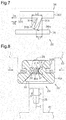
- the elastic lip 31 makes a transition from the state indicated by the two-dot chain line in Fig. 7 into the state indicated by the solid line in Fig. 7 .
- the lip distal-end section 31 B of the elastic lip 31 moves along the locus of the arc indicated by the two-dot chain line in Fig. 7 so as to move away from the inner circumferential surface 30S of the small diameter cylinder section 30C, and the elastic lip 31 therefore rises up.
- the friction force acting between the lip distal-end section 31 B and the abutting surface 26a becomes smaller. Due to the decrease in the friction force, the displacement of the abutting surface 26a in a reverse direction D2 together with the lip distal-end section 31 B is inhibited. In other words, the urging force that urges the lip basal-end section 31 A to displace the abutting surface 26a in the forward direction D1 is released at the elastic lip 31, so that the abutting surface 26a maintains being displaced along the forward direction D1, with respect to the lip basal-end section 31A serving as a fixed end.
- part of the vibration occurring in the cylinder head 41 is transmitted, to no small extent, also to the cylinder head cover 43 via the fastening screw 20 and the damping member 30.
- the vibration of the cylinder head cover 43 and the vibration of the cylinder head 41 are different from each other in the directions of the vibrations and the cycles of the vibrations.
- the vibration acts as an acting force that presses the lip distal-end sections 31 B of the elastic lips 31 against the abutting surface 26a, regardless of whether the vibration of the small diameter cylinder section 30C with respect to the abutting section 26 is in the direction along the radial direction of the small diameter cylinder section 30C or the vibration is in the direction along the axial direction of the small diameter cylinder section 30C.
- the application and the release of the stress F are repeated with timing that is different therebetween, the stress F pressing the lip distal-end section 31 B of the elastic lip 31 against the abutting surface 26a.
- the fastening screw 20 is displaced along the forward direction D1 with respect to the damping member 30, i.e., the cylinder head cover. Accordingly, the fastening screw 20 either rotates along the direction in which the fastening screw 20 is fastened onto the cylinder head 41 or receives a rotating force in the same direction.
- the fastening screw 20 is described as an example of the first component part and the fastening member, while the damping member 30 is described as an example of the second component part and the coupled member.
- the abutting surface 26a, the elastic lips 31, and the small diameter cylinder section 30C are described as examples of the abutting section, the urging section, and the state maintaining section, respectively.
- the cylinder head 41 is described as an example of the coupled target, whereas the fitting screw section 20A is described as an example of the screw-thread engaging section.
- the elastic lips 31 are omitted from the damping member 30.
- the outer circumferential surface of the abutting section 26 of the fastening screw 20 has elastic lips 26P serving as an example of the urging section.
- the inner circumferential surface of the damping member 30 has an abutting surface 30T serving as an example of the abutting section.
- the cylinder section of the small diameter cylinder section 30C functions as a state maintaining section that maintains the abutment between the elastic lips 26P and the abutting surface 30T.
- the position of the fastening screw 20 relative to the position of the damping member 30 changes along the direction in which the fastening screw 20 is fastened onto the cylinder head 41, every time the urging force is accumulated. As a result, it is possible to inhibit the fastening of the fastening screw 20 from becoming loose.
- the urging section is provided for one of the fastening member and the coupled member, while the abutting section is provided for the other of the fastening and the coupled members that is different from the member with which the urging section is provided.
- the abutting section 26 of the fastening screw 20 is provided with a recess having an opening toward the damping member 30.
- the inner surface of the recess functions as the abutting surface 26a serving as an example of the abutting section.
- the damping member 30 has the plurality of elastic lips 31 that protrude toward the abutting surface 26a and that serve as an example of the urging section. Each of the plurality of elastic lips 31 abuts against the abutting surface 26a.
- the circumferential wall of the abutting section 26 functions as a state maintaining section that maintains the abutment between the elastic lips 31 and the abutting surface 26a.
- the position of the fastening screw 20 relative to the position of the damping member 30 changes along the direction in which the fastening screw 20 is fastened onto the cylinder head 41, every time the urging force is accumulated. As a result, it is possible to inhibit the fastening of the fastening screw 20 from becoming loose.
- the urging section and the state maintaining section are provided for the mutually-different members, the member provided with the urging section is able to have a structure or to use a material that specializes in the accumulation and the release of the urging force which the urging section is required to realize.
- the member provided with the engagement section is able to have a structure or to use a material that specializes in maintaining the abutment state between the urging section and the abutting section.
- the state maintaining section may be provided for the fastening member or may be provided for the coupled member.
- the state maintaining member may be provided for at least one of the first component part and the second component part.
- the state maintaining member may be structured as another member that is different from the first component part or the second component part.
- the fastening screw 20 includes, on the outer circumferential surface of the abutting section 26, a screw-thread engaging section 20C that is either a male screw section or a female screw section that engages, via a screw thread, with the damping member 30.
- the inner circumferential surface of the damping member 30 is provided with a screw-thread engaged section 30K capable of engaging, via the screw thread, with the screw-thread engaging section 20C as a result of the fastening screw 20 rotating in the forward direction D1.
- the position of the fastening screw 20 relative to the position of the damping member 30 changes along the direction in which the fastening screw 20 is fastened onto the cylinder head 41 every time the urging force is accumulated. Further, the position of the fastening screw 20 relative to the position of the damping member 30 changes along the direction in which the fastening screw 20 is fastened onto the damping member 30, every time the urging force is accumulated.
- the screw-thread engaging section is provided for the fastening member, whereas the screw-thread engaged section that engages with the screw-thread engaging section may be provided for the coupling target or the coupled member.
- the fastening screw 20 includes, on the outer circumferential surface of the abutting section 26, the screw-thread engaging section 20C that is either a male screw section or a female screw section that engages, via a screw thread, with the damping member 30.
- the inner circumferential surface of the damping member 30 is provided with a screw-thread engaged section 30K capable of engaging, via the screw thread, with the screw-thread engaging section 20C as a result of the fastening screw 20 rotating in the forward direction D1.
- the female screw section of the cylinder head 41 and the fitting screw section 20A of the fastening screw 20 are omitted, while the cylinder head 41 and the fastening screw 20 are integrally formed.
- the fastening screw 20 and the cylinder head 41 are examples of the first component part having the abutting section, whereas the damping member 30 is an example of the second component part having the urging section. Further, because the fastening target of the fastening screw 20 is the damping member 30, it is possible to inhibit the fastening of the fastening screw 20 onto the damping member 30 from becoming loose.
- the fastening screw 20 includes a fitting screw section 20A that is either a male screw section or a female screw section that engages, via a screw thread, with the cylinder head 41.
- the fastening screw 20 further includes elastic lips 45 to be housed on the inside of the attachment hole 42 formed in the cylinder head 41.
- the inner circumferential surface of the attachment hole 42 functions as an abutting surface that abuts against the elastic lips 45. Further, the damping member 30 is omitted.
- the cylinder head 41 is an example of the first component part having the abutting section, whereas the fastening screw 20 is an example of the second component part having the urging section. Further, because the fastening target of the fastening screw 20 is the cylinder head 41, it is possible to inhibit the fastening of the fastening screw 20 onto the cylinder head 41 from becoming loose.
- a component-part driving member may be configured so that the outer circumferential surface of the fastening screw 20 is provided with a stopped member, while the inner circumferential surface of the damping member 30 is provided with a stopping member and so that, when the movement of the fastening screw 20 relative to the damping member 30 is developed excessively, the stopping member abuts against the stopped member so as to inhibit the relative movement with the abutment.
- the outer circumferential surface of the fastening screw 20 is provided with a basal-end receiving section 29F that serves as an example of a first stopped member and a distal-end receiving section 28G that serves as an example of a second stopped member.
- the basal-end receiving section 29F and the distal-end receiving section 28G sandwich the elastic lips 31 in the axial direction of the fastening screw 20.
- the basal-end receiving section 29F is in the shape of a frustum which has a sloped face 29T and of which the diameter is gradually reduced from the basal end of the fastening screw 20 toward the distal end thereof.
- the distal-end receiving section 28G is a recess receding toward the inner side in the radial direction of the fastening screw 20 and is formed along the entire circumference of the fastening screw 20.
- the inner circumferential surface of the damping member 30 is provided with an abutting opening 30G that serves as an example of a first stopping member positioned opposite to the basal-end receiving section 29F and is also provided with an abutting claw 30T that serves as an example of a second stopping member positioned opposite to the distal-end receiving section 28.
- the abutting opening 30G is in the shape of the cylindrical surface of a frustum which has a sloped face and of which the diameter is gradually enlarged from the distal end of the fastening screw 20 toward the basal end thereof.
- the abutting claw 30T is a projection protruding toward the inner side in the radial direction of the damping member 30 and is formed along the entire circumference of the damping member 30.
- a predetermined clearance CL is provided between the abutting opening 30G and the basal-end receiving section 29F. Further, a predetermined clearance CL is also provided between the abutting claw 30T and the distal-end receiving section 28G.
- the dimension of the clearance CL is arranged to be smaller than the maximum value tolerated by the elastic lips 31 among variable values of the distance between the lip distal-end sections 31 B and the lip supporting section 32. Further, the dimension of the clearance CL is arranged to be larger than a value sufficient for inhibiting the screw-thread engagement between the fastening screw 20 and the cylinder head 41 from becoming loose, among variable values of the distance between the lip distal-end sections 31 B and the lip supporting section 32.
- both the first stopped member and the second stopped member are recesses receding toward the inner side in the radial direction of the fastening screw 20, whereas both the first stopping member and the second stopping member are projections protruding toward the inner side in the radial direction of the damping member 30.
- both the first stopped member and the second stopped member are projections protruding toward the outer side in the radial direction of the fastening screw 20, whereas both the first stopping member and the second stopping member are recesses receding toward the outer side in the radial direction of the damping member 30.
- the first stopped member and the first stopping member may be omitted from the configuration described above.
- the second stopped member and the second stopping member may be omitted.
- this configuration also, it is acceptable to structure a single component-part driving mechanism by combining the abutment structure between the urging section and the abutting section described in at least one selected from the group consisting of the embodiment above, the first modification example, the second modification example, the third modification example, and the fourth modification example, with the abutment structure between the urging section and the abutting section described in the fifth modification example.
- each of the elastic lips 31 is not limited to the shape of the cylindrical surface of a conical frustum and may be, for example, a plate-like shape extending from the inner circumferential surface of the small diameter cylinder section 30C toward the inner side in the radial direction thereof. In that situation, it is sufficient if, when the stress F is applied to the elastic lips, the lip distal-end sections 31 B move in the forward direction D1 with respect to the lip basal-end sections 31 A.
- the urging section is shaped so that the accumulation of the urging force and the release of the urging force can be repeated due to the vibration of the urging section relative to the abutting section.
- the shape of the urging section may be modified, as appropriate, in accordance with the shape of the abutting section against which the urging section abuts.
- the quantity of the elastic lips 31 may be one or more.
- the positions of the plurality of elastic lips 31 may be mutually the same in the axial direction of the small diameter cylinder section 30C or may be different from one another in the axial direction of the small diameter cylinder section 30C.
- the distance between any two elastic lips 31 positioned adjacent to each other may be regular in the circumferential direction of the small diameter cylinder section 30C or may be irregular among the pairs of elastic lips 31 positioned adjacent to each other.
- each of the elastic lips 31 may be a smooth surface having no unevenness or may be an uneven surface obtained by applying a knurling process or a blasting process thereto.
- the abutting surface 26a of the abutting section 26 may be a smooth surface having no unevenness or may be an uneven surface obtained by applying a knurling process or a blasting process thereto.
- the surface of the abutting section and the surface of the urging section have such a surface structure where the accumulation of the urging force and the release of the urging force are repeated due to the vibration of the urging section relative to the abutting section, so that the positions thereof relative to each other are displaced in a predetermined direction due to the friction.
- the abutting surface 26a of the abutting section 26 may have, along the circumferential direction of the small diameter cylinder section 30C, a latch structure configured with a plurality of engagement sections capable of engaging with the elastic lips 31.
- the abutment structure between the abutting section and the urging section to be such a structure where the accumulation of the urging force and the release of the urging force are repeated due to the vibration of the urging section relative to the abutting section, so that the positions thereof relative to each other are displaced in a predetermined direction due to the engagement and the disengagement therebetween.
- the urging section included in the second component part does not necessarily have to be embodied as the elastic lips.
- the urging section may be structured so that the urging section itself exerts an elastic deformation by using, for example, fimbria, nylon brush, a plate spring made of resin, an elastically deformable metal plate, an elastic member having a bellow-like shape, or the like.
- the urging section may be structured so as to exert a mechanical deformation by using, for example, a link mechanism urged by a coil spring. In other words, it is sufficient if the urging section has a structure where the accumulation of the urging force and the release of the urging force are repeated due to the vibration of the urging section relative to the abutting section.
- the vibration of the urging section relative to the abutting section may be vibration caused by an engine installed in a vehicle, a watercraft, an airplane, or the like, or may be vibration caused by, for example, a motor installed in a vehicle, an air conditioner, a washing machine, a refrigerator, or the like, or pulsating motion caused by a pipe through which fluid flows.
- the component part driven by the component-part driving mechanism is not limited to a fastening screw attached to a cylinder head and may be, for example, a fastening member used for any of various types of interior decorations of a vehicle, a cap attached as a molding end cap, or a fastening member used in a driving mechanism for a louver of an air conditioner.
- the component part driven by the component-part driving mechanism may be, for example, an anchor bolt used for a tunnel, a bolt used for a beam of a bridge, or the like.
- the component part driven by the component-part driving mechanism may be, for example, a banner turning-and-rising inhibiting member that inhibits a banner from turning and rising, a fastening member used for attaching a cover of a ventilation fan to a wall surface, a cord locking mechanism used for preventing a shoelace from becoming loose, or the like.
- the component part driven by the component-part driving mechanism may be a fastening member used for any of various temporary fixing purposes. In other words, the component part may be any member that can be displaced by vibration in an undesirable direction.
Landscapes
- Engineering & Computer Science (AREA)
- General Engineering & Computer Science (AREA)
- Mechanical Engineering (AREA)
- Chemical & Material Sciences (AREA)
- Combustion & Propulsion (AREA)
- Vibration Prevention Devices (AREA)
- Cylinder Crankcases Of Internal Combustion Engines (AREA)
- Springs (AREA)
Abstract
Description
- The present disclosure is related to a component-part driving mechanism that drives a component part.
- A known configuration of a supporting structure that supports a cylinder head cover with a cylinder head makes use of joining between a fastening member attached to the cylinder head and a damping member attached to the cylinder head cover. The fastening member may be, for example, a male screw member that engages, via a screw thread, with a female screw section formed in the cylinder head, whereas the damping member may be, for example, an elastic ring fitted into a fitting groove formed in the cylinder head cover. Further, as a result of the head of the male screw member being fitted into a fitting hole formed in the elastic ring, the cylinder head and the cylinder head cover are indirectly joined with each other (see Patent Document 1, for example).
- Among fastening members that can be attached to a cylinder head, attention is paid to a fastener that is made of resin and has locking pieces obtained by cutting out some portions of a male screw section of a male screw member along the axial direction, for the purpose of reducing the labor required by the fastening process. Unlike the male screw section, the locking pieces formed on the fastener made of resin are able to warp along the axial direction. Accordingly, the operation of fastening the resin fastener is sufficiently accomplished by inserting the resin fastener into a hole having a female screw section, instead of rotating the resin fastener (see
Patent Document 2, for example). -
- Patent Document 1
Japanese Laid-open Patent Publication No.2005-331067 -
Patent Document 2
Japanese Laid-open Patent Publication No.2012-57778 - Part of the vibration occurring in the cylinder head is usually transmitted, to no small extent, also to the cylinder head cover via the damping member. In that situation, because the vibration of the cylinder head cover and the vibration of the cylinder head are different from each other in the directions of the vibrations and the cycles of the vibrations, the difference between the vibrations acts in such a direction that loosens the fastening between the cylinder head and the fastening member.
- The problem where the position of a component part unexpectedly changes in an undesirable direction not only can be observed in a structure where the position of a fastening member used for a fastening purpose changes in such a direction that releases the fastening, but also is common to all structures including a component part that receives vibration, such as a structure in which, for example, the position of a temporary fastening member, which is used on the premise that the fastening is to be released, changes in such a direction that promotes the fastening.
- An object of the present disclosure is to provide a component-part driving mechanism that prevents the situation where the position of a component part changes in an undesirable direction.
- In one aspect of a component-part driving mechanism of the present disclosure, the component-part driving mechanism that changes a relative position of a second component part relative to a position of a first component part includes: an abutting section provided for the first component part; an urging section provided for the second component part and accumulates an urging force as a result of changes in a distance between the abutting section and the urging section, said urging force serving to change the relative position in a predetermined direction; and a state maintaining section that maintains a state in which the urging section is abutting against the abutting section. Further, the abutting section and the urging section displace the relative position in the predetermined direction as a result of a repetition of accumulating and releasing of the urging force due to vibration of the urging section relative to the abutting section.
- According to the one aspect of the component-part driving mechanism of the present disclosure described above, when the second component part vibrates relative to the first component part, the urging section vibrates relative to the abutting section so that the accumulation of the urging force in the urging section and the release of the urging force in the urging section are repeated. Further, the position of the second component part relative to that of the first component part changes in the predetermined direction every time the urging force is released. As a result, it is possible to inhibit the position of the second component part relative to that of the first component part from changing in an undesirable direction.
- In another aspect of the component-part driving mechanism of the present disclosure, it is desirable that the abutting section is configured to receive the urging force in a direction in which the urging force acts.
- According to the one aspect of the component-part driving mechanism of the present disclosure described above, because the urging force exerted by the urging section is received by the abutting section, the displacement of the position of the second component part relative to that of the first component part is developed smoothly when the urging force is released.
- In yet another aspect of the component-part driving mechanism of the present disclosure, one of the first and the second component parts is a fastening member that rotates and fastens onto a coupling target, while the other of the first and the second component parts that is not the fastening member is a coupled member that is fastened onto the coupling target via the fastening member. Further, it is desirable that one of the coupling target and the coupled member includes a screw-thread engaged section that is either a female screw section or a male screw section and that the fastening member includes a screw-thread engaging section that engages with the screw-thread engaged section.
- According to the one aspect of the component-part driving mechanism of the present disclosure described above, the urging force exerted by the urging section is able to inhibit the thread-screw engagement between the one of the coupling target and the coupled member and the fastening member from becoming loose.
- In yet another aspect of the component-part driving mechanism of the present disclosure, it is desirable that the urging section is provided for one of the fastening member and the coupled member and that the state maintaining section is provided for another one of the fastening and the coupled members that is not provided with the urging section.
- According to the one aspect of the component-part driving mechanism of the present disclosure described above, because the urging section and the state maintaining section are provided for the mutually-different members, the member provided with the urging section is able to have a structure that specializes in the accumulation and the release of the urging force which the urging section is required to realize. Further, the member provided with the engagement section is able to have a structure that specializes in maintaining the abutment state between the urging section and the abutting section.
- In yet another aspect of the component-part driving mechanism of the present disclosure, it is desirable that the fastening member has a shaft-like shape and that the coupled member is in a shape of a cylinder positioned on an outer circumference of the fastening member.
- According to the one aspect of the component-part driving mechanism of the present disclosure described above, it is possible to inhibit the position of the coupled member relative to that of the fastening member from changing in an undesirable direction by using the simple shapes of the fastening member that has the shaft-like shape and the coupled member that is in the shape of the cylinder positioned on the outer circumference of the fastening member.
- In yet another aspect of the component-part driving member of the present disclosure, it is desirable that the fastening member has an outer circumference enlarged section that is positioned adjacent to the abutting section.
- According to the one aspect of the component-part driving mechanism of the present disclosure described above, because the outer circumference enlarged section that is positioned adjacent to the abutting section is able to prevent the urging section from coming out of contact with the abutting section, the abutment state between the urging section and the abutting section is easily maintained.
- In yet another aspect of the component-part driving mechanism of the present disclosure, it is desirable that the component-part driving mechanism includes a plurality of the urging sections and that the plurality of urging sections are arranged in a row along a direction in which the fastening member rotates.
- According to the one aspect of the component-part driving mechanism of the present disclosure described above, because the urging force applied from the second component part to the first component part is enhanced, it is possible to better inhibit the position of the second component part relative to that of the first component part from changing in an undesirable direction.
- In yet another aspect of the component-part driving mechanism of the present disclosure, it is desirable that the screw-thread engaging section has an elastic force that enables the screw-thread engaging section to go over a screw section of the screw-thread engaged section.
- According to the one aspect of the component-part driving mechanism of the present disclosure described above, because the thread-screw engaged section and the thread-screw engaging section engage with each other via the screw thread, as a result of the screw-thread engaging section being inserted into the screw-thread engaged section. Consequently, it is possible to save the labor required by achieving the screw-thread engagement, compared to the situation where the screw-thread engagement therebetween is achieved by rotating the screw-thread engaging section.
-
-
Fig. 1 is an exploded perspective view illustrating an exploded perspective structure of a fastening-member driving mechanism according to an embodiment together with a part of a cylinder head and a part of a cylinder head cover, wherein a component-part driving mechanism of the present disclosure is embodied as the fastening-member driving mechanism. -
Fig. 2 is a cross-sectional view illustrating a cross-sectional structure of the fastening-member driving mechanism according to the embodiment, together with a part of a cross-sectional structure of the cylinder head and a part of a cross-sectional structure of the cylinder head cover. -
Fig. 3 is a perspective view of a perspective structure of a damping member included in the fastening-member driving mechanism according to the embodiment. -
Fig. 4 is a cross-sectional view illustrating a cross-sectional structure of the damping member included in the fastening-member driving mechanism according to the embodiment, the cross-sectional structure being taken along line 4-4 inFig. 2 . -
Fig. 5 is a cross-sectional view illustrating a cross-sectional structure of the damping member included in the fastening-member driving mechanism according to the embodiment, the cross-sectional structure being taken along line 5-5 inFig. 2 . -
Fig. 6 is a conceptual drawing illustrating a function of elastic lips included in the fastening-member driving mechanism according to the embodiment and illustrating a relationship between stress and an urging force acting on an elastic lip. -
Fig. 7 is a conceptual drawing illustrating the function of the elastic lips included in the fastening-member driving mechanism according to the embodiment and illustrating the relationship between the stress and the urging force acting on the elastic lip. -
Fig. 8 is an action diagram illustrating an action of the fastening-member driving mechanism according to the embodiment and illustrating a relationship between vibration acting on the elastic lips and rotation of the fastening member. -
Fig. 9 is a configuration diagram that conceptually illustrates elements included in the fastening-member driving mechanism according to the embodiment and connections among the elements. -
Fig. 10 is a configuration diagram illustrating a configuration of a component-part driving mechanism according to a first modification example. -
Fig. 11 is a configuration diagram illustrating a configuration of a component-part driving mechanism according to a second modification example. -
Fig. 12 is a configuration diagram illustrating a configuration of a component-part driving mechanism according to a third modification example. -
Fig. 13 is a configuration diagram illustrating a configuration of a component-part driving mechanism according to a fourth modification example. -
Fig. 14 is a configuration diagram illustrating another configuration of the component-part driving mechanism according to the fourth modification example. -
Fig. 15 is a configuration diagram illustrating another configuration of a component-part driving mechanism according to a fifth modification example. - An embodiment in which a component-part driving mechanism of the present disclosure is embodied as a fastening-member driving mechanism will be explained, with reference to
Figs. 1 to 8 . First, an overall configuration of the fastening-member driving mechanism will be explained with reference toFig. 1 , together with a cylinder head and a cylinder head cover to which the fastening-member driving mechanism is applied. - As illustrated in
Fig. 1 , a fastening-member driving mechanism 10 includes afastening screw 20 that serves as an example of the first component part and also serves as an example of the fastening member; and adamping member 30 made of resin that serves as an example of the second component part and also serves as an example of the coupled member. Thefastening screw 20 includes: afitting screw section 20A that is made of resin and that serves as an example of the screw-thread engaging section; and a fittedpin 20B that is made of resin. - The
fitting screw section 20A includes: aninsertion bottom section 21 having a disc shape; and twofitting leg sections 22 extending in the shape of a V from the circumferential edge of theinsertion bottom section 21 toward the above of theinsertion bottom section 21. The twofitting leg sections 22 are integrally formed with theinsertion bottom section 21. - A
cylinder head 41 serving as an example of the coupling target has formed therein anattachment hole 42 into which thefastening screw 20 can be attached. Theattachment hole 42 has formed therewith a female screw section serving as an example of the screw-thread engaged section. Theinsertion bottom section 21 is sized so as to be able to go into theattachment hole 42. The twofitting leg sections 22 are connected to the circumferential edge of theinsertion bottom section 21 in such positions that oppose each other. - Of the faces of each of the two
fitting leg sections 22, the face opposing the otherfitting leg section 22 will be referred to as an inner face of thefitting leg section 22. Of the faces of each of thefitting leg sections 22, the face positioned on the opposite side from the inner face will be referred to as an outer face of thefitting leg section 22. In each of the twofitting leg sections 22, the section connected to theinsertion bottom section 21 will be referred to as a basal-end section of thefitting leg section 22. Of the two ends of each of thefitting leg sections 22, the end positioned on the opposite side from the basal-end section will be referred to as a distal-end section of thefitting leg section 22. - From the inner face of each of the two
fitting leg sections 22, one basal-end-sidefitting projection 23a and one distal-end-sidefitting projection 23b protrude toward the otherfitting leg section 22. In each of thefitting leg sections 22, the basal-end-sidefitting projection 23a and the distal-end-sidefitting projection 23b are arranged along the extending direction of thefitting leg section 22 while having a space therebetween. - From the outer face of each of the two
fitting leg sections 22, a plurality of lockingpieces 24 protrude outward in the radial direction of theinsertion bottom section 21. In each of the twofitting leg sections 22, the plurality of lockingpieces 24 are arranged in a row along the extending direction of thefitting leg section 22 while being positioned at regular intervals. The space formed between any two of the lockingpieces 24 that are positioned adjacent to each other in one of thefitting leg sections 22 is arranged to oppose a corresponding one of the lockingpieces 24 in the otherfitting leg section 22. The plurality of lockingpieces 24 provided in the twofitting leg sections 22 function as a male screw section that is capable of engaging, in the manner of a screw thread, with the female screw section formed in theattachment hole 42. - The fitted
pin 20B includes ashaft section 25 extending along the central axis of theinsertion bottom section 21 and an abuttingsection 26 that is cone-shaped and extends upward from theshaft section 25. Theshaft section 25 and the abuttingsection 26 are integrally formed. - The
shaft section 25 is in the shape of a circular pillar of which the outside diameter is substantially equal to that of theinsertion bottom section 21. Theshaft section 25 is sized so as to be able to go into theattachment hole 42 formed in thecylinder head 41. On the outer circumferential surface of theshaft section 25, two basal-end-sidefitting holes 25a and one distal-end-sidefitting hole 25b are formed in the manner of recesses receding toward the inner side in the radial direction of theshaft section 25. The two basal-end-sidefitting holes 25a oppose each other in the radial direction of theshaft section 25. The one distal-end-sidefitting hole 25b penetrates through theshaft section 25 along the radial direction of theshaft section 25. The position of thefitting screw section 20A relative to that of the fittedpin 20B is determined when each of the two basal-end-sidefitting holes 25a has a corresponding one of the two basal-end-sidefitting projections 23a fitted therein, and at the same time, the two distal-end-sidefitting projections 23b are fitted into the one distal-end-sidefitting hole 25b. - As long as it is possible to determine the position of the
fitting screw section 20A relative to that of the fittedpin 20B, it is acceptable to omit, for example, the basal-end-sidefitting projections 23a and the basal-end-sidefitting holes 25a. Alternatively, the distal-end-sidefitting projections 23b and the distal-end-sidefitting hole 25b may be omitted. Further, the quantity of thefitting leg sections 22 of thefitting screw section 20A, the quantity of the basal-end-sidefitting holes 25a of theshaft section 25, and the quantity of the distal-end-sidefitting hole 25b of theshaft section 25 may be modified as necessary, on the premise that it is possible to determine the position of thefitting screw section 20A relative to that of the fittedpin 20B. Further, as long as thefastening screw 20 has a screw section capable of engaging, via a screw thread, with the screw section formed in theattachment hole 42 and the abuttingsection 26, thefastening screw 20 may be configured so that thefitting screw section 20A and the fittedpin 20B are integrally formed. - The outer circumferential surface of the abutting
section 26 has anabutting surface 26a that is curved in the manner of a recess receding toward the inner side in the radial direction of the abuttingsection 26. Theabutting surface 26a is a circular-arc surface that structures a continuous recess along the circumferential direction of the abuttingsection 26 and is formed along the entire circumference of the abuttingsection 26. Theabutting surface 26a is positioned substantially at the center of the abuttingsection 26 in the axial direction of the abuttingsection 26. Along the axial direction of the abuttingsection 26, the abuttingsurface 26a divides theone abutting section 26 into a basal-end-side abutting section 27 serving as an example of the outer circumference enlarged section and a distal-end-side abutting section 28. - The outer circumferential surface of the abutting
section 26 has a plurality of hollowedsections 29 that are arranged along the circumferential direction of the abuttingsection 26. However, it is possible to select, as appropriate, whether the hollowedsections 29 should be provided or not, depending on the amount of resin required by the shaping of the abuttingsection 26 and the level of rigidity required of the abuttingsection 26. - The damping
member 30 is in the shape of three-tiered circular cylinders and includes: a largediameter cylinder section 30A positioned closest to thefitting screw section 20A; a mediumdiameter cylinder section 30B positioned most distant from thefitting screw section 20A; and a smalldiameter cylinder section 30C positioned between the largediameter cylinder section 30A and the mediumdiameter cylinder section 30B. - A
cylinder head cover 43 has afitting section 44 that is in the shape of a circular cylinder of which the opening is reduced in diameter. The opening of thefitting section 44 is a circular hole having an opening radius R1. The interior of thefitting section 44 has an inside radius R2 that is larger than the opening radius R1. The outside diameter of the largediameter cylinder section 30A is sufficiently larger than double the inside radius R2. The outside diameter of the mediumdiameter cylinder section 30B is larger than double the opening radius R1 and is substantially equal to double the inside radius R2. The outside diameter of the smalldiameter cylinder section 30C is substantially equal to double the opening radius R1. The dampingmember 30 is fixed to thecylinder head cover 43, when the mediumdiameter cylinder section 30B is fitted to the inside of thefitting section 44 while, at the same time, the smalldiameter cylinder section 30C is fitted into the opening section of thefitting section 44. On the inner circumferential surface of the smalldiameter cylinder section 30C, a plurality ofelastic lips 31 structuring an urging section protrude toward the inside of the smalldiameter cylinder section 30C. - A mode of assembling the
fastening screw 20 and the dampingmember 30 together will be explained, with reference toFig. 2 . - As illustrated in
Fig. 2 , thefastening screw 20 is inserted into theattachment hole 42, while the basal-end-sidefitting projections 23a are fitted into the basal-end-sidefitting holes 25a, and also, the distal-end-sidefitting projections 23b are fitted into the distal-end-sidefitting hole 25b. In that situation, the plurality of lockingpieces 24 formed on thefitting leg sections 22 are able to warp along the axial direction of theattachment hole 42. Further, the plurality of lockingpieces 24 are formed only on the twofitting leg sections 22 in the inner circumferential direction of theattachment hole 42. In other words, the lockingpieces 24 are positioned only in parts along the inner circumferential direction of theattachment hole 42. Accordingly, the attachment of thefastening screw 20 to the female screw section of theattachment hole 42 is smoothly accomplished by inserting thefastening screw 20, without the need to rotate thefastening screw 20. - The medium
diameter cylinder section 30B of the dampingmember 30 is fitted to the inside of thefitting section 44, and also, the smalldiameter cylinder section 30C of the dampingmember 30 is fitted to the opening section of thefitting section 44. Further, as indicated with the arrow inFig. 2 , starting with the state in which the largediameter cylinder section 30A and the distal-end-side abutting section 28 oppose each other, thecylinder head cover 43 is pressed against thecylinder head 41. As a result, the inner circumferential surface of the largediameter cylinder section 30A abuts against the outer circumferential surface of the abuttingsection 26, so that theabutting surface 26a is fitted to the inside of the smalldiameter cylinder section 30C. Further, thefastening screw 20 and the dampingmember 30 are assembled with each other, so that thecylinder head 41 and thecylinder head cover 43 are indirectly coupled with each other, via thefastening screw 20 and the dampingmember 30. - Detailed structures of the
fastening screw 20 and the dampingmember 30 will be explained, with reference toFigs. 3 to 6 . - As illustrated in
Fig. 3 , onelip supporting section 32 protrudes toward the inside of the smalldiameter cylinder section 30C on the inner circumferential surface of the smalldiameter cylinder section 30C of the dampingmember 30. Thelip supporting section 32 has an annular shape extending entirely along the circumferential direction of the smalldiameter cylinder section 30C and also has a semi-circular shape as viewed on a cross-sectional plane that includes the central axis of the smalldiameter cylinder section 30C. Thelip supporting section 32 forms, on the inner circumferential surface of the smalldiameter cylinder section 30C, a semi-circular arc surface extending entirely along the circumferential direction of the smalldiameter cylinder section 30C. On the semi-circular arc surface of thelip supporting section 32 and the inner circumferential surface of the smalldiameter cylinder section 30C, the plurality ofelastic lips 31 that are integrally formed therewith are arranged in a row along the circumferential direction of the smalldiameter cylinder section 30C. - The circumferential direction of the small
diameter cylinder section 30C can go in two directions. One of the two circumferential directions will be referred to as a forward direction D1 and is the direction in which thefastening screw 20 is fastened onto thecylinder head 41. Each of the plurality ofelastic lips 31 is in the shape of a bowl opening toward the forward direction D1. Each of the plurality ofelastic lips 31 is in the shape of the cylindrical surface of a conical frustum that is substantially concentric with the central axis of the annular-shapedlip supporting section 32. The upper side section of the cylindrical surface of the conical frustum will be referred to as a lip basal-end section 31 A, whereas the bottom side section of the cylindrical surface of the conical frustum will be referred to as a lip distal-end section 31 B. Each of the plurality ofelastic lips 31 is connected to thelip supporting section 32 by the entirety of the lip basal-end section 31 A and is positioned apart from thelip supporting section 32 at the lip distal-end section 31 B. Each of the plurality ofelastic lips 31 tolerates an elastic deformation that changes the distance between the lip distal-end section 31 B and thelip supporting section 32. - As illustrated in
Fig. 4 , the plurality ofelastic lips 31 are arranged at regular intervals along the inner circumferential surface of the smalldiameter cylinder section 30C. In each of all theelastic lips 31, the lip distal-end section 31 B is positioned in the forward direction D1 from the lip basal-end section 31A. In each of all theelastic lips 31, the lip distal-end section 31B is in contact with theabutting surface 26a of the abuttingsection 26. The cylinder section of the smalldiameter cylinder section 30C functions as a state maintaining section that maintains the state where the lip distal-end sections 31 B and theabutting surface 26a abut against each other, by pressing the lip distal-end section 31 B against the abuttingsurface 26a while using an elastic force exerted by the cylinder section. - The angle θ formed by the direction in which each of the lip distal-
end sections 31 B protrudes from the lip basal-end section 31A and the direction of the tangent line of theabutting surface 26a is an acute angle. The elastic force of theelastic lips 31 acting from the lip basal-end sections 31 A toward the lip distal-end sections 31 B is received by the abuttingsurface 26a, as an urging force that urges theabutting surface 26a along the forward direction D1. - As indicated by the two-dot chain line in
Fig. 5 , on a cross-sectional plane including the central axis C1 of the abuttingsection 26, the abuttingsurface 26a of the abuttingsection 26 is in the shape of a semi-circular arc, while the two ends of the semi-circular arc are substantially aligned along the central axis C1. Further, as indicated by the solid line inFig. 5 , on a cross-sectional plane including the central axis C1 of the abuttingsection 26, each of the lip distal-end sections 31 B of theelastic lips 31 is also in the shape of a semi-circular arc, while the two ends of the semi-circular arc are also aligned along the central axis C1. As viewed on a cross-sectional plane that includes the central axis C1 of the abuttingsection 26, the outline of each of the lip distal-end sections 31 B is substantially analogous to the shape of theabutting surface 26a. The curvature of each of the lip distal-end sections 31 B is slightly larger than the curvature of theabutting surface 26a. While theabutting surface 26a is positioned on the inside of the smalldiameter cylinder section 30C, substantially the entirety of each of the lip distal-end sections 31 B having the semi-circular arc shape abuts against the abuttingsurface 26a. Thus, any change in the position of the smalldiameter cylinder section 30C with respect to the abuttingsection 26 is transformed into an elastic deformation of one or more of theelastic lips 31, regardless of whether the change is a change along the radial direction of the smalldiameter cylinder section 30C or the change is a change along the axial direction of the smalldiameter cylinder section 30C. - Operations of the fastening-member driving mechanism will be explained while a focus is placed on operations of the
elastic lips 31, with reference toFigs. 6 to 8 . - As illustrated in
Fig. 6 , when the smalldiameter cylinder section 30C receives stress F along the direction in which the smalldiameter cylinder section 30C approaches the abuttingsection 26, theelastic lip 31 makes a transition from the state indicated by the two-dot chain line inFig. 6 into the state indicated by the solid line inFig. 6 . In other words, the lip distal-end section 31 B of theelastic lip 31 moves along the locus of the arc indicated by the two-dot chain line inFig. 6 so as to approach an innercircumferential surface 30S of the smalldiameter cylinder section 30C, and theelastic lip 31 therefore falls down. - In that situation, before the stress F (see the bold white arrow) acts on the small
diameter cylinder section 30C, the distance between the lip basal-end section 31A and the lip distal-end section 31 B in the forward direction D1 is a release distance L1, while the resistance pressing theabutting surface 26a against the lip distal-end section 31 B is a release resistance F1 working as a vertical resistance. In contrast, when the stress F is acting on the smalldiameter cylinder section 30C, the distance between the innercircumferential surface 30S of the smalldiameter cylinder section 30C and theabutting surface 26a becomes shorter, so that the distance between the lip basal-end section 31 A and the lip distal-end section 31 B in the forward direction D1 becomes longer so as to be an accumulation distance L2, and also, the resistance pressing theabutting surface 26a against the lip distal-end section 31 B becomes larger so as to be an accumulation resistance F2 working as a vertical resistance. - As a result, the friction force acting between the lip distal-
end section 31 B and theabutting surface 26a becomes larger. Due to the increase in the friction force, the abuttingsurface 26a is displaced in the forward direction D1, together with the lip distal-end section 31 B. In other words, an urging force that urges the lip basal-end section 31 A to displace theabutting surface 26a in the forward direction D1 is accumulated in theelastic lip 31 so as to act on the abuttingsection 26. - As illustrated in
Fig. 7 , when the stress F that caused the smalldiameter cylinder section 30C to approach the abuttingsection 26 is released, theelastic lip 31 makes a transition from the state indicated by the two-dot chain line inFig. 7 into the state indicated by the solid line inFig. 7 . In other words, the lip distal-end section 31 B of theelastic lip 31 moves along the locus of the arc indicated by the two-dot chain line inFig. 7 so as to move away from the innercircumferential surface 30S of the smalldiameter cylinder section 30C, and theelastic lip 31 therefore rises up. - In that situation, as a result of the stress F being released, the distance between the inner
circumferential surface 30S of the smalldiameter cylinder section 30C and theabutting surface 26a becomes longer, and the distance between the lip basal-end section 31A and the lip distal-end section 31 B in the forward direction D1 returns from the accumulation distance L2 to the release distance L1. Further, the resistance pressing theabutting surface 26a against the lip distal-end section 31 B also decreases from the accumulation resistance F2 to the release resistance F1. - As a result, the friction force acting between the lip distal-
end section 31 B and theabutting surface 26a becomes smaller. Due to the decrease in the friction force, the displacement of theabutting surface 26a in a reverse direction D2 together with the lip distal-end section 31 B is inhibited. In other words, the urging force that urges the lip basal-end section 31 A to displace theabutting surface 26a in the forward direction D1 is released at theelastic lip 31, so that theabutting surface 26a maintains being displaced along the forward direction D1, with respect to the lip basal-end section 31A serving as a fixed end. - As illustrated in
Fig. 8 , part of the vibration occurring in thecylinder head 41 is transmitted, to no small extent, also to thecylinder head cover 43 via thefastening screw 20 and the dampingmember 30. In that situation, the vibration of thecylinder head cover 43 and the vibration of thecylinder head 41 are different from each other in the directions of the vibrations and the cycles of the vibrations. In addition, because substantially the entirety of the lip distal-end sections 31 B each having the semi-circular arc shape abuts against the abuttingsurface 26a, the vibration acts as an acting force that presses the lip distal-end sections 31 B of theelastic lips 31 against the abuttingsurface 26a, regardless of whether the vibration of the smalldiameter cylinder section 30C with respect to the abuttingsection 26 is in the direction along the radial direction of the smalldiameter cylinder section 30C or the vibration is in the direction along the axial direction of the smalldiameter cylinder section 30C. - As a result, in each of the plurality of
elastic lips 31, the application and the release of the stress F are repeated with timing that is different therebetween, the stress F pressing the lip distal-end section 31 B of theelastic lip 31 against the abuttingsurface 26a. Further, every time the application and the release of the stress F are repeated in each of the plurality ofelastic lips 31, thefastening screw 20 is displaced along the forward direction D1 with respect to the dampingmember 30, i.e., the cylinder head cover. Accordingly, thefastening screw 20 either rotates along the direction in which thefastening screw 20 is fastened onto thecylinder head 41 or receives a rotating force in the same direction. Consequently, even if the screw-thread engagement between thefastening screw 20 and thecylinder head 41 is loosened, it is possible to re-tighten the screw-thread engagement. In addition, when the screw-thread engagement between thefastening screw 20 and thecylinder head 41 has not yet become loose, it is also possible to inhibit the screw-thread engagement between thefastening screw 20 and thecylinder head 41 from starting to become loose. - According to the embodiment described above, it is possible to achieve advantageous effects listed below:
- (1) When the
cylinder head cover 43 vibrates relative to thecylinder head 41, theelastic lips 31 vibrate relative to theabutting surface 26a, so that the accumulation and the release of the urging force are repeated in theelastic lips 31. Further, the position of thefastening screw 20 relative to the position of the dampingmember 30 changes along the direction in which thefastening screw 20 is fastened onto thecylinder head 41 every time the urging force is accumulated. As a result, it is possible to inhibit the fastening of thefastening screw 20 from becoming loose. - (2) Each of the plurality of lip distal-
end sections 31 B individually abuts against the abuttingsurface 26a entirely along the circumferential direction of theabutting surface 26a, while the direction in which each of theelastic lips 31 extends and the direction of the tangent line of theabutting surface 26a forms an acute angle. In addition, the urging force released by theelastic lips 31 is received by the abuttingsurface 26a. Consequently, the displacement of theabutting surface 26a along the forward direction D1 is smoothly developed when the urging force is accumulated. - (3) The cylinder section of the small
diameter cylinder section 30C has the function of maintaining the abutment between theelastic lips 31 and theabutting surface 26a. The cylinder section of the smalldiameter cylinder section 30C and theelastic lips 31 are integrally formed. Consequently, it is easier to maintain the abutment between theelastic lips 31 and theabutting surface 26a, compared to the situation where the plurality ofelastic lips 31 and the state maintaining section that maintains the abutment thereof are structured as separate members. - (4) It is possible to realize the structure that inhibits the fastening of the
fastening screw 20 from becoming loose by using the simple shapes of thefastening screw 20 that has a shaft-like shape and the dampingmember 30 that is in the shape of a cylinder positioned on the outer circumference of thefastening screw 20. - (5) Because each of the plurality of lip distal-
end sections 31 B applies the urging force to theabutting surface 26a, the urging force applied from the dampingmember 30 to thefastening screw 20 is enhanced by as much as the quantity of theelastic lips 31, compared to the situation where only a singleelastic lip 31 applies an urging force to theabutting surface 26a. Consequently, it is possible to inhibit the fastening of thefastening screw 20 from becoming loose, with higher certainty. - (6) The
cylinder head 41 and thefastening screw 20 engage with each other via the screw thread, as a result of thefastening screw 20 being inserted into theattachment hole 42. Consequently, it is possible to save the labor required by achieving the screw-thread engagement, compared to the situation where the screw-thread engagement therebetween is achieved by rotating thefastening screw 20. - The embodiment described above may be modified as described below.
- As illustrated in
Fig. 9 , in the embodiment described above, thefastening screw 20 is described as an example of the first component part and the fastening member, while the dampingmember 30 is described as an example of the second component part and the coupled member. Further, the abuttingsurface 26a, theelastic lips 31, and the smalldiameter cylinder section 30C are described as examples of the abutting section, the urging section, and the state maintaining section, respectively. Also, thecylinder head 41 is described as an example of the coupled target, whereas thefitting screw section 20A is described as an example of the screw-thread engaging section. These elements may be modified as described below. - As illustrated in
Fig. 10 , theelastic lips 31 are omitted from the dampingmember 30. The outer circumferential surface of the abuttingsection 26 of thefastening screw 20 haselastic lips 26P serving as an example of the urging section. The inner circumferential surface of the dampingmember 30 has anabutting surface 30T serving as an example of the abutting section. The cylinder section of the smalldiameter cylinder section 30C functions as a state maintaining section that maintains the abutment between theelastic lips 26P and theabutting surface 30T. - In this configuration also, the position of the
fastening screw 20 relative to the position of the dampingmember 30 changes along the direction in which thefastening screw 20 is fastened onto thecylinder head 41, every time the urging force is accumulated. As a result, it is possible to inhibit the fastening of thefastening screw 20 from becoming loose. - It is also acceptable to structure a single component-part driving mechanism by combining the abutment structure between the urging section and the abutting section described in the embodiment above, with the abutment structure between the urging section and the abutting section described in the first modification example.
- In other words, it is sufficient when the urging section is provided for one of the fastening member and the coupled member, while the abutting section is provided for the other of the fastening and the coupled members that is different from the member with which the urging section is provided.
- As illustrated in
Fig. 11 , the abuttingsection 26 of thefastening screw 20 is provided with a recess having an opening toward the dampingmember 30. The inner surface of the recess functions as the abuttingsurface 26a serving as an example of the abutting section. The dampingmember 30 has the plurality ofelastic lips 31 that protrude toward theabutting surface 26a and that serve as an example of the urging section. Each of the plurality ofelastic lips 31 abuts against the abuttingsurface 26a. The circumferential wall of the abuttingsection 26 functions as a state maintaining section that maintains the abutment between theelastic lips 31 and theabutting surface 26a. - In this configuration also, the position of the
fastening screw 20 relative to the position of the dampingmember 30 changes along the direction in which thefastening screw 20 is fastened onto thecylinder head 41, every time the urging force is accumulated. As a result, it is possible to inhibit the fastening of thefastening screw 20 from becoming loose. Further, because the urging section and the state maintaining section are provided for the mutually-different members, the member provided with the urging section is able to have a structure or to use a material that specializes in the accumulation and the release of the urging force which the urging section is required to realize. Further, the member provided with the engagement section is able to have a structure or to use a material that specializes in maintaining the abutment state between the urging section and the abutting section. - In this configuration also, it is acceptable to structure a single component-part driving mechanism by combining the abutment structure between the urging section and the abutting section described in at least one of the embodiment above and the first modification example, with the abutment structure between the urging section and the abutting section described in the second modification example.
- In other words, the state maintaining section may be provided for the fastening member or may be provided for the coupled member. The state maintaining member may be provided for at least one of the first component part and the second component part. Alternatively, the state maintaining member may be structured as another member that is different from the first component part or the second component part.
- As illustrated in
Fig. 12 , thefastening screw 20 includes, on the outer circumferential surface of the abuttingsection 26, a screw-thread engaging section 20C that is either a male screw section or a female screw section that engages, via a screw thread, with the dampingmember 30. The inner circumferential surface of the dampingmember 30 is provided with a screw-thread engagedsection 30K capable of engaging, via the screw thread, with the screw-thread engaging section 20C as a result of thefastening screw 20 rotating in the forward direction D1. - In this configuration also, the position of the
fastening screw 20 relative to the position of the dampingmember 30 changes along the direction in which thefastening screw 20 is fastened onto thecylinder head 41 every time the urging force is accumulated. Further, the position of thefastening screw 20 relative to the position of the dampingmember 30 changes along the direction in which thefastening screw 20 is fastened onto the dampingmember 30, every time the urging force is accumulated. - As a result, it is possible to inhibit the fastening of the
fastening screw 20 onto thecylinder head 41 from becoming loose. In addition, even in the situation where the fastening of thefastening screw 20 onto the dampingmember 30 becomes loose, it is possible to tighten the fastening. - In this configuration also, it is acceptable to structure a single component-part driving mechanism by combining the abutment structure between the urging section and the abutting section described in at least one selected from the group consisting of the embodiment above, the first modification example, and the second modification example, with the abutment structure between the urging section and the abutting section described in the third modification example.
- In other words, the screw-thread engaging section is provided for the fastening member, whereas the screw-thread engaged section that engages with the screw-thread engaging section may be provided for the coupling target or the coupled member.
- As illustrated in
Fig. 13 , thefastening screw 20 includes, on the outer circumferential surface of the abuttingsection 26, the screw-thread engaging section 20C that is either a male screw section or a female screw section that engages, via a screw thread, with the dampingmember 30. The inner circumferential surface of the dampingmember 30 is provided with a screw-thread engagedsection 30K capable of engaging, via the screw thread, with the screw-thread engaging section 20C as a result of thefastening screw 20 rotating in the forward direction D1. Further, the female screw section of thecylinder head 41 and thefitting screw section 20A of thefastening screw 20 are omitted, while thecylinder head 41 and thefastening screw 20 are integrally formed. - In this configuration, the
fastening screw 20 and thecylinder head 41 are examples of the first component part having the abutting section, whereas the dampingmember 30 is an example of the second component part having the urging section. Further, because the fastening target of thefastening screw 20 is the dampingmember 30, it is possible to inhibit the fastening of thefastening screw 20 onto the dampingmember 30 from becoming loose. - As illustrated in
Fig. 14 , thefastening screw 20 includes afitting screw section 20A that is either a male screw section or a female screw section that engages, via a screw thread, with thecylinder head 41. Thefastening screw 20 further includeselastic lips 45 to be housed on the inside of theattachment hole 42 formed in thecylinder head 41. The inner circumferential surface of theattachment hole 42 functions as an abutting surface that abuts against theelastic lips 45. Further, the dampingmember 30 is omitted. - In this configuration, the
cylinder head 41 is an example of the first component part having the abutting section, whereas thefastening screw 20 is an example of the second component part having the urging section. Further, because the fastening target of thefastening screw 20 is thecylinder head 41, it is possible to inhibit the fastening of thefastening screw 20 onto thecylinder head 41 from becoming loose. - In this configuration also, it is acceptable to structure a single component-part driving mechanism by combining the abutment structure between the urging section and the abutting section described in at least one selected from the group consisting of the embodiment above, the first modification example, the second modification example, and the third modification example, with the abutment structure between the urging section and the abutting section described in the fourth modification example.
- When strong vibration keeps occurring in the
cylinder head 41 described above, the application and the release of the stress F are repeated with a large magnitude that causes theelastic lips 31 to fall down excessively and thus shortens the life of theelastic lips 31. To cope with this situation, for the purpose of extending the life of theelastic lips 31, a component-part driving member may be configured so that the outer circumferential surface of thefastening screw 20 is provided with a stopped member, while the inner circumferential surface of the dampingmember 30 is provided with a stopping member and so that, when the movement of thefastening screw 20 relative to the dampingmember 30 is developed excessively, the stopping member abuts against the stopped member so as to inhibit the relative movement with the abutment. - For example, as illustrated in
Fig. 15 , the outer circumferential surface of thefastening screw 20 is provided with a basal-end receiving section 29F that serves as an example of a first stopped member and a distal-end receiving section 28G that serves as an example of a second stopped member. The basal-end receiving section 29F and the distal-end receiving section 28G sandwich theelastic lips 31 in the axial direction of thefastening screw 20. The basal-end receiving section 29F is in the shape of a frustum which has a slopedface 29T and of which the diameter is gradually reduced from the basal end of thefastening screw 20 toward the distal end thereof. The distal-end receiving section 28G is a recess receding toward the inner side in the radial direction of thefastening screw 20 and is formed along the entire circumference of thefastening screw 20. - Further, the inner circumferential surface of the damping
member 30 is provided with anabutting opening 30G that serves as an example of a first stopping member positioned opposite to the basal-end receiving section 29F and is also provided with anabutting claw 30T that serves as an example of a second stopping member positioned opposite to the distal-end receiving section 28. Theabutting opening 30G is in the shape of the cylindrical surface of a frustum which has a sloped face and of which the diameter is gradually enlarged from the distal end of thefastening screw 20 toward the basal end thereof. Theabutting claw 30T is a projection protruding toward the inner side in the radial direction of the dampingmember 30 and is formed along the entire circumference of the dampingmember 30. - A predetermined clearance CL is provided between the
abutting opening 30G and the basal-end receiving section 29F. Further, a predetermined clearance CL is also provided between theabutting claw 30T and the distal-end receiving section 28G. The dimension of the clearance CL is arranged to be smaller than the maximum value tolerated by theelastic lips 31 among variable values of the distance between the lip distal-end sections 31 B and thelip supporting section 32. Further, the dimension of the clearance CL is arranged to be larger than a value sufficient for inhibiting the screw-thread engagement between thefastening screw 20 and thecylinder head 41 from becoming loose, among variable values of the distance between the lip distal-end sections 31 B and thelip supporting section 32. - With the structure described above, even when the
fastening screw 20 moves upward excessively, for example, it is possible to suppress the upward movement of thefastening screw 20 within a range where the excessive fall-down of theelastic lips 31 can be avoided, due to the abutment between theabutting opening 30G and the basal-end receiving section 29F and the abutment between theabutting claw 30T and the distal-end receiving section 28G. Further, for example, even when thefastening screw 20 moves downward excessively, it is possible to suppress the downward movement of thefastening screw 20 within a range where the excessive fall-down of theelastic lips 31 can be avoided, due to the abutment between theabutting claw 30T and the distal-end receiving section 28G. Further, even when thefastening screw 20 moves in the left-and-right directions excessively, it is possible to suppress the movement of thefastening screw 20 within a range where the excessive fall-down of theelastic lips 31 can be avoided, due to the abutment between theabutting opening 30G and the basal-end receiving section 29F and the abutment between theabutting claw 30T and the distal-end receiving section 28G. Consequently, it is possible to extend the life of theelastic lips 31. - Alternatively, another arrangement is acceptable in which both the first stopped member and the second stopped member are recesses receding toward the inner side in the radial direction of the
fastening screw 20, whereas both the first stopping member and the second stopping member are projections protruding toward the inner side in the radial direction of the dampingmember 30. Conversely, yet another arrangement is also acceptable in which both the first stopped member and the second stopped member are projections protruding toward the outer side in the radial direction of thefastening screw 20, whereas both the first stopping member and the second stopping member are recesses receding toward the outer side in the radial direction of the dampingmember 30. Further, the first stopped member and the first stopping member may be omitted from the configuration described above. Alternatively, the second stopped member and the second stopping member may be omitted. - Furthermore, in this configuration also, it is acceptable to structure a single component-part driving mechanism by combining the abutment structure between the urging section and the abutting section described in at least one selected from the group consisting of the embodiment above, the first modification example, the second modification example, the third modification example, and the fourth modification example, with the abutment structure between the urging section and the abutting section described in the fifth modification example.
- The shape of each of the
elastic lips 31 is not limited to the shape of the cylindrical surface of a conical frustum and may be, for example, a plate-like shape extending from the inner circumferential surface of the smalldiameter cylinder section 30C toward the inner side in the radial direction thereof. In that situation, it is sufficient if, when the stress F is applied to the elastic lips, the lip distal-end sections 31 B move in the forward direction D1 with respect to the lip basal-end sections 31 A. - In other words, it is sufficient if the urging section is shaped so that the accumulation of the urging force and the release of the urging force can be repeated due to the vibration of the urging section relative to the abutting section. The shape of the urging section may be modified, as appropriate, in accordance with the shape of the abutting section against which the urging section abuts.
- The quantity of the
elastic lips 31 may be one or more. - For example, the positions of the plurality of
elastic lips 31 may be mutually the same in the axial direction of the smalldiameter cylinder section 30C or may be different from one another in the axial direction of the smalldiameter cylinder section 30C. The distance between any twoelastic lips 31 positioned adjacent to each other may be regular in the circumferential direction of the smalldiameter cylinder section 30C or may be irregular among the pairs ofelastic lips 31 positioned adjacent to each other. - The surface of each of the
elastic lips 31 may be a smooth surface having no unevenness or may be an uneven surface obtained by applying a knurling process or a blasting process thereto. Further, the abuttingsurface 26a of the abuttingsection 26 may be a smooth surface having no unevenness or may be an uneven surface obtained by applying a knurling process or a blasting process thereto. - In other words, it is sufficient if the surface of the abutting section and the surface of the urging section have such a surface structure where the accumulation of the urging force and the release of the urging force are repeated due to the vibration of the urging section relative to the abutting section, so that the positions thereof relative to each other are displaced in a predetermined direction due to the friction.
- For example, the abutting
surface 26a of the abuttingsection 26 may have, along the circumferential direction of the smalldiameter cylinder section 30C, a latch structure configured with a plurality of engagement sections capable of engaging with theelastic lips 31. In other words, it is acceptable to arrange the abutment structure between the abutting section and the urging section to be such a structure where the accumulation of the urging force and the release of the urging force are repeated due to the vibration of the urging section relative to the abutting section, so that the positions thereof relative to each other are displaced in a predetermined direction due to the engagement and the disengagement therebetween. - The urging section included in the second component part does not necessarily have to be embodied as the elastic lips. The urging section may be structured so that the urging section itself exerts an elastic deformation by using, for example, fimbria, nylon brush, a plate spring made of resin, an elastically deformable metal plate, an elastic member having a bellow-like shape, or the like. Alternatively, the urging section may be structured so as to exert a mechanical deformation by using, for example, a link mechanism urged by a coil spring. In other words, it is sufficient if the urging section has a structure where the accumulation of the urging force and the release of the urging force are repeated due to the vibration of the urging section relative to the abutting section.
- The vibration of the urging section relative to the abutting section may be vibration caused by an engine installed in a vehicle, a watercraft, an airplane, or the like, or may be vibration caused by, for example, a motor installed in a vehicle, an air conditioner, a washing machine, a refrigerator, or the like, or pulsating motion caused by a pipe through which fluid flows.
- The component part driven by the component-part driving mechanism is not limited to a fastening screw attached to a cylinder head and may be, for example, a fastening member used for any of various types of interior decorations of a vehicle, a cap attached as a molding end cap, or a fastening member used in a driving mechanism for a louver of an air conditioner. Further, in architectural structures, the component part driven by the component-part driving mechanism may be, for example, an anchor bolt used for a tunnel, a bolt used for a beam of a bridge, or the like. Further, in housing facilities and clothing items, the component part driven by the component-part driving mechanism may be, for example, a banner turning-and-rising inhibiting member that inhibits a banner from turning and rising, a fastening member used for attaching a cover of a ventilation fan to a wall surface, a cord locking mechanism used for preventing a shoelace from becoming loose, or the like. Further, the component part driven by the component-part driving mechanism may be a fastening member used for any of various temporary fixing purposes. In other words, the component part may be any member that can be displaced by vibration in an undesirable direction.
- The description, the claims, the drawings, and the abstract of Japanese Patent Application No.
2013-261137 filed on December 18, 2013
Claims (8)
- A component-part driving mechanism that changes a relative position of a second component part relative to a position of a first component part, comprising:an abutting section provided for the first component part;an urging section provided for the second component part and accumulates an urging force as a result of changes in a distance between the abutting section and the urging section, said urging force serving to change the relative position in a predetermined direction; anda state maintaining section that maintains a state in which the urging section is abutting against the abutting section, characterized in thatthe abutting section and the urging section displace the relative position in the predetermined direction as a result of a repetition of accumulating and releasing of the urging force due to vibration of the urging section relative to the abutting section.
- The component-part driving mechanism according to claim 1, wherein
the abutting section is configured to receive the urging force in a direction in which the urging force acts. - The component-part driving mechanism according to claim 1 or 2, wherein
one of the first and the second component parts is a fastening member that rotates and fastens onto a coupling target,
the other of the first and the second component parts that is not the fastening member is a coupled member that is fastened onto the coupling target via the fastening member,
one of the coupling target and the coupled member includes a screw-thread engaged section that is either a female screw section or a male screw section, and
the fastening member includes a screw-thread engaging section that engages with the screw-thread engaged section. - The component-part driving mechanism according to claim 3, wherein
the urging section is provided for one of the fastening member and the coupled member, and
the state maintaining section is provided for another one of the fastening and the coupled members that is not provided with the urging section. - The component-part driving mechanism according to claim 4, wherein
the fastening member has a shaft-like shape, and
the coupled member is in a shape of a cylinder positioned on an outer circumference of the fastening member. - The component-part driving mechanism according to any one of claims 3 to 5, wherein
the fastening member has an outer circumference enlarged section that is positioned adjacent to the abutting section. - The component-part driving mechanism according to any one of claims 3 to 6, comprising a plurality of the urging sections, wherein
the plurality of urging sections are arranged along a direction in which the fastening member rotates. - The component-part driving mechanism according to any one of claims 3 to 7, wherein
the screw-thread engaging section has an elastic force that enables the screw-thread engaging section to go over a screw section of the screw-thread engaged section.
Applications Claiming Priority (2)
| Application Number | Priority Date | Filing Date | Title |
|---|---|---|---|
| JP2013261137 | 2013-12-18 | ||
| PCT/JP2014/083136 WO2015093437A1 (en) | 2013-12-18 | 2014-12-15 | Member drive mechanism |
Publications (3)
| Publication Number | Publication Date |
|---|---|
| EP3085975A1 true EP3085975A1 (en) | 2016-10-26 |
| EP3085975A4 EP3085975A4 (en) | 2017-07-12 |
| EP3085975B1 EP3085975B1 (en) | 2022-03-30 |
Family
ID=53402783
Family Applications (1)
| Application Number | Title | Priority Date | Filing Date |
|---|---|---|---|
| EP14872534.4A Not-in-force EP3085975B1 (en) | 2013-12-18 | 2014-12-15 | Member drive mechanism |
Country Status (6)
| Country | Link |
|---|---|
| US (1) | US9879707B2 (en) |
| EP (1) | EP3085975B1 (en) |
| JP (1) | JP6211629B2 (en) |
| KR (2) | KR20150071644A (en) |
| CN (1) | CN105874226B (en) |
| WO (1) | WO2015093437A1 (en) |
Cited By (1)
| Publication number | Priority date | Publication date | Assignee | Title |
|---|---|---|---|---|
| DE102016120650A1 (en) * | 2016-10-28 | 2018-05-03 | Böllhoff Verbindungstechnik GmbH | Ring-shaped plug-in coupling and method for establishing a connection between components by means of the annular plug-in coupling |
Families Citing this family (16)
| Publication number | Priority date | Publication date | Assignee | Title |
|---|---|---|---|---|
| US10835947B2 (en) | 2014-07-09 | 2020-11-17 | The Boeing Company | Method for building an assembly fixture for supporting a fuselage assembly |
| CN108591087B (en) * | 2017-10-24 | 2019-12-06 | 赛而乐电器有限公司 | A back net subassembly assembly hasp structure for fan |
| DE102017124887A1 (en) * | 2017-10-24 | 2019-04-25 | Lisi Automotive Kkp Gmbh & Co. Kg | connection system |
| US11519446B2 (en) | 2018-11-05 | 2022-12-06 | Illinois Tool Works Inc. | Fastener feedback feature |
| CN109667820A (en) * | 2018-12-14 | 2019-04-23 | 中国航空工业集团公司西安航空计算技术研究所 | A kind of elastic locking mechanism |
| US11608849B2 (en) | 2019-01-04 | 2023-03-21 | Illinois Tool Works Inc. | Grommet removal assemblies and methods |
| USD905546S1 (en) | 2019-01-04 | 2020-12-22 | Illinois Tool Works Inc. | Fastener |
| USD889221S1 (en) * | 2019-01-04 | 2020-07-07 | Illinois Tool Works Inc. | Fastener removal tool |
| DE202019105135U1 (en) * | 2019-09-17 | 2020-12-18 | Montaplast Gmbh | Fastening element and component arrangement with fastening element |
| US11346385B2 (en) | 2020-04-06 | 2022-05-31 | Illinois Tool Works Inc. | Grommet |
| US20220013257A1 (en) | 2020-07-10 | 2022-01-13 | Illinois Tool Works Inc. | Grommet |
| CN113931911A (en) * | 2020-06-29 | 2022-01-14 | 酷码科技股份有限公司 | Combined assembly |
| TWI748583B (en) | 2020-07-30 | 2021-12-01 | 和碩聯合科技股份有限公司 | Latch and housing device comprising the same |
| CN116097009A (en) * | 2020-09-11 | 2023-05-09 | 阿尔卑斯阿尔派株式会社 | Connection structure |
| USD990300S1 (en) | 2021-12-15 | 2023-06-27 | Illinois Tool Works Inc. | Fastener |
| USD991024S1 (en) | 2021-12-15 | 2023-07-04 | Illinois Tool Works Inc. | Fastener |
Family Cites Families (20)
| Publication number | Priority date | Publication date | Assignee | Title |
|---|---|---|---|---|
| US2727407A (en) | 1950-09-12 | 1955-12-20 | Syntron Co | Flexible elastomer |
| JPS49123476U (en) * | 1973-02-24 | 1974-10-23 | ||
| US4318208A (en) * | 1979-10-05 | 1982-03-09 | Illinois Tool Works Inc. | Fastening system |
| US5562375A (en) * | 1994-11-09 | 1996-10-08 | The United States Of America As Represented By The Administrator Of The National Aeronautics And Space Administration | Push type fastener |
| US5580204A (en) * | 1995-03-07 | 1996-12-03 | Textron Inc. | Panel attachment system |
| US5647713A (en) * | 1996-05-22 | 1997-07-15 | Trw Inc. | Plastic panel fastener and method of forming the same |
| US5868537A (en) * | 1998-05-29 | 1999-02-09 | Illinois Tool Works Inc. | Sponge head retainer pin |
| GB9816478D0 (en) * | 1998-07-30 | 1998-09-23 | Ford Motor Co | Instrument panel retention fixing device |
| US6077011A (en) * | 1999-08-02 | 2000-06-20 | Walker; Philip Marvin | Push button panel fastener |
| JP2002122118A (en) | 2000-06-06 | 2002-04-26 | Satoshi Takagi | Metal fitting for automatically adjusting space |
| US6431585B1 (en) * | 2000-10-05 | 2002-08-13 | Lear Corporation | Dual stage fastener |
| US7029221B2 (en) | 2002-08-01 | 2006-04-18 | Newfrey Llc | Sleeve device with internal fins for holding a piece such as a bolt in a bore |
| DE20216836U1 (en) * | 2002-10-31 | 2003-02-06 | Böllhoff GmbH, 33649 Bielefeld | Plug-in coupling with three-dimensional compensation movement |
| US7017239B2 (en) * | 2002-12-17 | 2006-03-28 | Illinois Tool Works Inc. | Component connection system |
| US7082919B2 (en) * | 2003-03-28 | 2006-08-01 | Toyoda Gosei Co., Ltd. | Mounting structure for engine cover |
| JP2005331067A (en) | 2004-05-21 | 2005-12-02 | Daiwa Kasei Ind Co Ltd | Design cover mounting structure for engine |
| JP2006082969A (en) | 2004-09-17 | 2006-03-30 | Micro Products:Kk | Article carrying device and article carrying method |
| JP4719132B2 (en) | 2006-11-21 | 2011-07-06 | ダイキョーニシカワ株式会社 | Cover member mounting structure |
| JP2008129350A (en) | 2006-11-21 | 2008-06-05 | Ricoh Co Ltd | Image forming apparatus, developer for image formation and process cartridge |
| JP2012057778A (en) | 2010-09-13 | 2012-03-22 | Nifco Inc | Fastener |
-
2014
- 2014-12-09 KR KR1020140176190A patent/KR20150071644A/en active Application Filing
- 2014-12-15 CN CN201480068040.8A patent/CN105874226B/en not_active Expired - Fee Related
- 2014-12-15 EP EP14872534.4A patent/EP3085975B1/en not_active Not-in-force
- 2014-12-15 US US15/104,578 patent/US9879707B2/en active Active
- 2014-12-15 WO PCT/JP2014/083136 patent/WO2015093437A1/en active Application Filing
- 2014-12-15 JP JP2015553527A patent/JP6211629B2/en active Active
-
2017
- 2017-02-09 KR KR1020170018285A patent/KR20170018869A/en not_active Application Discontinuation
Cited By (1)
| Publication number | Priority date | Publication date | Assignee | Title |
|---|---|---|---|---|
| DE102016120650A1 (en) * | 2016-10-28 | 2018-05-03 | Böllhoff Verbindungstechnik GmbH | Ring-shaped plug-in coupling and method for establishing a connection between components by means of the annular plug-in coupling |
Also Published As
| Publication number | Publication date |
|---|---|
| CN105874226A (en) | 2016-08-17 |
| EP3085975B1 (en) | 2022-03-30 |
| KR20170018869A (en) | 2017-02-20 |
| EP3085975A4 (en) | 2017-07-12 |
| JPWO2015093437A1 (en) | 2017-03-16 |
| US9879707B2 (en) | 2018-01-30 |
| US20160319855A1 (en) | 2016-11-03 |
| WO2015093437A1 (en) | 2015-06-25 |
| KR20150071644A (en) | 2015-06-26 |
| CN105874226B (en) | 2017-10-20 |
| JP6211629B2 (en) | 2017-10-11 |
Similar Documents
| Publication | Publication Date | Title |
|---|---|---|
| US9879707B2 (en) | Component-part driving mechanism | |
| US5885022A (en) | Ball joint with polymer housing | |
| US9140294B2 (en) | High extraction force ball socket | |
| US6379093B1 (en) | Captive fastener member and system for joining two work pieces | |
| CN106122399B (en) | Pulley device for tension wheel or idle wheel | |
| US9046176B2 (en) | Hydraulic auto-tensioner | |
| JP2007138944A (en) | Holding system and method | |
| US8794860B1 (en) | Rotational connector device | |
| US6789656B2 (en) | Clutch cover assembly | |
| JP7448811B2 (en) | chain guide | |
| JP6678556B2 (en) | Split seal ring press-fitting jig | |
| KR20110005702A (en) | Rescue unit | |
| KR101877063B1 (en) | Clutch disc and friction lining comprising a reduced-inertia friction material adhered to a foil | |
| JP6035661B2 (en) | Transmission chain | |
| JP4303848B2 (en) | Sealing device for linear drive mechanism | |
| JP2005500495A (en) | Drum brake assembly | |
| CN211821045U (en) | Installing support, water pump assembly and vehicle | |
| JP2008232249A (en) | Dust cover fixing structure | |
| JP2018004067A (en) | Falling-off prevention device for fastening nut | |
| TWI828553B (en) | Spinning reel for fishing | |
| CN212838903U (en) | Inner and outer sleeve type one-way fastener | |
| JP5716176B2 (en) | Chain transmission wheel | |
| JPH0241370Y2 (en) | ||
| JP6267345B2 (en) | Fastener | |
| CN214533939U (en) | Tolerance adjusting part capable of automatically compensating spacing |
Legal Events
| Date | Code | Title | Description |
|---|---|---|---|
| PUAI | Public reference made under article 153(3) epc to a published international application that has entered the european phase |
Free format text: ORIGINAL CODE: 0009012 |
|
| 17P | Request for examination filed |
Effective date: 20160704 |
|
| AK | Designated contracting states |
Kind code of ref document: A1 Designated state(s): AL AT BE BG CH CY CZ DE DK EE ES FI FR GB GR HR HU IE IS IT LI LT LU LV MC MK MT NL NO PL PT RO RS SE SI SK SM TR |
|
| AX | Request for extension of the european patent |
Extension state: BA ME |
|
| RIN1 | Information on inventor provided before grant (corrected) |
Inventor name: WATANABE, YASUHIRO |
|
| DAX | Request for extension of the european patent (deleted) | ||
| A4 | Supplementary search report drawn up and despatched |
Effective date: 20170613 |
|
| RIC1 | Information provided on ipc code assigned before grant |
Ipc: F16B 39/02 20060101AFI20170607BHEP Ipc: F16B 31/04 20060101ALI20170607BHEP |
|
| STAA | Information on the status of an ep patent application or granted ep patent |
Free format text: STATUS: EXAMINATION IS IN PROGRESS |
|
| 17Q | First examination report despatched |
Effective date: 20190410 |
|
| STAA | Information on the status of an ep patent application or granted ep patent |
Free format text: STATUS: EXAMINATION IS IN PROGRESS |
|
| GRAP | Despatch of communication of intention to grant a patent |
Free format text: ORIGINAL CODE: EPIDOSNIGR1 |
|
| STAA | Information on the status of an ep patent application or granted ep patent |
Free format text: STATUS: GRANT OF PATENT IS INTENDED |
|
| INTG | Intention to grant announced |
Effective date: 20211029 |
|
| GRAS | Grant fee paid |
Free format text: ORIGINAL CODE: EPIDOSNIGR3 |
|
| GRAA | (expected) grant |
Free format text: ORIGINAL CODE: 0009210 |
|
| STAA | Information on the status of an ep patent application or granted ep patent |
Free format text: STATUS: THE PATENT HAS BEEN GRANTED |
|
| AK | Designated contracting states |
Kind code of ref document: B1 Designated state(s): AL AT BE BG CH CY CZ DE DK EE ES FI FR GB GR HR HU IE IS IT LI LT LU LV MC MK MT NL NO PL PT RO RS SE SI SK SM TR |
|
| REG | Reference to a national code |
Ref country code: GB Ref legal event code: FG4D |
|
| REG | Reference to a national code |
Ref country code: CH Ref legal event code: EP |
|
| REG | Reference to a national code |
Ref country code: AT Ref legal event code: REF Ref document number: 1479447 Country of ref document: AT Kind code of ref document: T Effective date: 20220415 |
|
| REG | Reference to a national code |
Ref country code: DE Ref legal event code: R096 Ref document number: 602014083049 Country of ref document: DE |
|
| REG | Reference to a national code |
Ref country code: IE Ref legal event code: FG4D |
|
| REG | Reference to a national code |
Ref country code: LT Ref legal event code: MG9D |
|
| PG25 | Lapsed in a contracting state [announced via postgrant information from national office to epo] |
Ref country code: SE Free format text: LAPSE BECAUSE OF FAILURE TO SUBMIT A TRANSLATION OF THE DESCRIPTION OR TO PAY THE FEE WITHIN THE PRESCRIBED TIME-LIMIT Effective date: 20220330 Ref country code: RS Free format text: LAPSE BECAUSE OF FAILURE TO SUBMIT A TRANSLATION OF THE DESCRIPTION OR TO PAY THE FEE WITHIN THE PRESCRIBED TIME-LIMIT Effective date: 20220330 Ref country code: NO Free format text: LAPSE BECAUSE OF FAILURE TO SUBMIT A TRANSLATION OF THE DESCRIPTION OR TO PAY THE FEE WITHIN THE PRESCRIBED TIME-LIMIT Effective date: 20220630 Ref country code: LT Free format text: LAPSE BECAUSE OF FAILURE TO SUBMIT A TRANSLATION OF THE DESCRIPTION OR TO PAY THE FEE WITHIN THE PRESCRIBED TIME-LIMIT Effective date: 20220330 Ref country code: HR Free format text: LAPSE BECAUSE OF FAILURE TO SUBMIT A TRANSLATION OF THE DESCRIPTION OR TO PAY THE FEE WITHIN THE PRESCRIBED TIME-LIMIT Effective date: 20220330 Ref country code: BG Free format text: LAPSE BECAUSE OF FAILURE TO SUBMIT A TRANSLATION OF THE DESCRIPTION OR TO PAY THE FEE WITHIN THE PRESCRIBED TIME-LIMIT Effective date: 20220630 |
|
| REG | Reference to a national code |
Ref country code: NL Ref legal event code: MP Effective date: 20220330 |
|
| REG | Reference to a national code |
Ref country code: AT Ref legal event code: MK05 Ref document number: 1479447 Country of ref document: AT Kind code of ref document: T Effective date: 20220330 |
|
| PG25 | Lapsed in a contracting state [announced via postgrant information from national office to epo] |
Ref country code: LV Free format text: LAPSE BECAUSE OF FAILURE TO SUBMIT A TRANSLATION OF THE DESCRIPTION OR TO PAY THE FEE WITHIN THE PRESCRIBED TIME-LIMIT Effective date: 20220330 Ref country code: GR Free format text: LAPSE BECAUSE OF FAILURE TO SUBMIT A TRANSLATION OF THE DESCRIPTION OR TO PAY THE FEE WITHIN THE PRESCRIBED TIME-LIMIT Effective date: 20220701 Ref country code: FI Free format text: LAPSE BECAUSE OF FAILURE TO SUBMIT A TRANSLATION OF THE DESCRIPTION OR TO PAY THE FEE WITHIN THE PRESCRIBED TIME-LIMIT Effective date: 20220330 |
|
| PG25 | Lapsed in a contracting state [announced via postgrant information from national office to epo] |
Ref country code: NL Free format text: LAPSE BECAUSE OF FAILURE TO SUBMIT A TRANSLATION OF THE DESCRIPTION OR TO PAY THE FEE WITHIN THE PRESCRIBED TIME-LIMIT Effective date: 20220330 |
|
| PG25 | Lapsed in a contracting state [announced via postgrant information from national office to epo] |
Ref country code: SM Free format text: LAPSE BECAUSE OF FAILURE TO SUBMIT A TRANSLATION OF THE DESCRIPTION OR TO PAY THE FEE WITHIN THE PRESCRIBED TIME-LIMIT Effective date: 20220330 Ref country code: SK Free format text: LAPSE BECAUSE OF FAILURE TO SUBMIT A TRANSLATION OF THE DESCRIPTION OR TO PAY THE FEE WITHIN THE PRESCRIBED TIME-LIMIT Effective date: 20220330 Ref country code: RO Free format text: LAPSE BECAUSE OF FAILURE TO SUBMIT A TRANSLATION OF THE DESCRIPTION OR TO PAY THE FEE WITHIN THE PRESCRIBED TIME-LIMIT Effective date: 20220330 Ref country code: PT Free format text: LAPSE BECAUSE OF FAILURE TO SUBMIT A TRANSLATION OF THE DESCRIPTION OR TO PAY THE FEE WITHIN THE PRESCRIBED TIME-LIMIT Effective date: 20220801 Ref country code: ES Free format text: LAPSE BECAUSE OF FAILURE TO SUBMIT A TRANSLATION OF THE DESCRIPTION OR TO PAY THE FEE WITHIN THE PRESCRIBED TIME-LIMIT Effective date: 20220330 Ref country code: EE Free format text: LAPSE BECAUSE OF FAILURE TO SUBMIT A TRANSLATION OF THE DESCRIPTION OR TO PAY THE FEE WITHIN THE PRESCRIBED TIME-LIMIT Effective date: 20220330 Ref country code: CZ Free format text: LAPSE BECAUSE OF FAILURE TO SUBMIT A TRANSLATION OF THE DESCRIPTION OR TO PAY THE FEE WITHIN THE PRESCRIBED TIME-LIMIT Effective date: 20220330 Ref country code: AT Free format text: LAPSE BECAUSE OF FAILURE TO SUBMIT A TRANSLATION OF THE DESCRIPTION OR TO PAY THE FEE WITHIN THE PRESCRIBED TIME-LIMIT Effective date: 20220330 |
|
| PG25 | Lapsed in a contracting state [announced via postgrant information from national office to epo] |
Ref country code: PL Free format text: LAPSE BECAUSE OF FAILURE TO SUBMIT A TRANSLATION OF THE DESCRIPTION OR TO PAY THE FEE WITHIN THE PRESCRIBED TIME-LIMIT Effective date: 20220330 Ref country code: IS Free format text: LAPSE BECAUSE OF FAILURE TO SUBMIT A TRANSLATION OF THE DESCRIPTION OR TO PAY THE FEE WITHIN THE PRESCRIBED TIME-LIMIT Effective date: 20220730 Ref country code: AL Free format text: LAPSE BECAUSE OF FAILURE TO SUBMIT A TRANSLATION OF THE DESCRIPTION OR TO PAY THE FEE WITHIN THE PRESCRIBED TIME-LIMIT Effective date: 20220330 |
|
| REG | Reference to a national code |
Ref country code: DE Ref legal event code: R097 Ref document number: 602014083049 Country of ref document: DE |
|
| PG25 | Lapsed in a contracting state [announced via postgrant information from national office to epo] |
Ref country code: DK Free format text: LAPSE BECAUSE OF FAILURE TO SUBMIT A TRANSLATION OF THE DESCRIPTION OR TO PAY THE FEE WITHIN THE PRESCRIBED TIME-LIMIT Effective date: 20220330 |
|
| PLBE | No opposition filed within time limit |
Free format text: ORIGINAL CODE: 0009261 |
|
| STAA | Information on the status of an ep patent application or granted ep patent |
Free format text: STATUS: NO OPPOSITION FILED WITHIN TIME LIMIT |
|
| 26N | No opposition filed |
Effective date: 20230103 |
|
| PG25 | Lapsed in a contracting state [announced via postgrant information from national office to epo] |
Ref country code: SI Free format text: LAPSE BECAUSE OF FAILURE TO SUBMIT A TRANSLATION OF THE DESCRIPTION OR TO PAY THE FEE WITHIN THE PRESCRIBED TIME-LIMIT Effective date: 20220330 |
|
| REG | Reference to a national code |
Ref country code: DE Ref legal event code: R119 Ref document number: 602014083049 Country of ref document: DE |
|
| PG25 | Lapsed in a contracting state [announced via postgrant information from national office to epo] |
Ref country code: IT Free format text: LAPSE BECAUSE OF FAILURE TO SUBMIT A TRANSLATION OF THE DESCRIPTION OR TO PAY THE FEE WITHIN THE PRESCRIBED TIME-LIMIT Effective date: 20220330 |
|
| REG | Reference to a national code |
Ref country code: CH Ref legal event code: PL |
|
| GBPC | Gb: european patent ceased through non-payment of renewal fee |
Effective date: 20221215 |
|
| REG | Reference to a national code |
Ref country code: BE Ref legal event code: MM Effective date: 20221231 |
|
| PG25 | Lapsed in a contracting state [announced via postgrant information from national office to epo] |
Ref country code: LU Free format text: LAPSE BECAUSE OF NON-PAYMENT OF DUE FEES Effective date: 20221215 |
|
| PG25 | Lapsed in a contracting state [announced via postgrant information from national office to epo] |
Ref country code: LI Free format text: LAPSE BECAUSE OF NON-PAYMENT OF DUE FEES Effective date: 20221231 Ref country code: IE Free format text: LAPSE BECAUSE OF NON-PAYMENT OF DUE FEES Effective date: 20221215 Ref country code: GB Free format text: LAPSE BECAUSE OF NON-PAYMENT OF DUE FEES Effective date: 20221215 Ref country code: DE Free format text: LAPSE BECAUSE OF NON-PAYMENT OF DUE FEES Effective date: 20230701 Ref country code: CH Free format text: LAPSE BECAUSE OF NON-PAYMENT OF DUE FEES Effective date: 20221231 |
|
| PG25 | Lapsed in a contracting state [announced via postgrant information from national office to epo] |
Ref country code: FR Free format text: LAPSE BECAUSE OF NON-PAYMENT OF DUE FEES Effective date: 20221231 Ref country code: BE Free format text: LAPSE BECAUSE OF NON-PAYMENT OF DUE FEES Effective date: 20221231 |
|
| PG25 | Lapsed in a contracting state [announced via postgrant information from national office to epo] |
Ref country code: HU Free format text: LAPSE BECAUSE OF FAILURE TO SUBMIT A TRANSLATION OF THE DESCRIPTION OR TO PAY THE FEE WITHIN THE PRESCRIBED TIME-LIMIT; INVALID AB INITIO Effective date: 20141215 |
|
| PG25 | Lapsed in a contracting state [announced via postgrant information from national office to epo] |
Ref country code: CY Free format text: LAPSE BECAUSE OF FAILURE TO SUBMIT A TRANSLATION OF THE DESCRIPTION OR TO PAY THE FEE WITHIN THE PRESCRIBED TIME-LIMIT Effective date: 20220330 |
|
| PG25 | Lapsed in a contracting state [announced via postgrant information from national office to epo] |
Ref country code: MK Free format text: LAPSE BECAUSE OF FAILURE TO SUBMIT A TRANSLATION OF THE DESCRIPTION OR TO PAY THE FEE WITHIN THE PRESCRIBED TIME-LIMIT Effective date: 20220330 |
|
| PG25 | Lapsed in a contracting state [announced via postgrant information from national office to epo] |
Ref country code: MC Free format text: LAPSE BECAUSE OF FAILURE TO SUBMIT A TRANSLATION OF THE DESCRIPTION OR TO PAY THE FEE WITHIN THE PRESCRIBED TIME-LIMIT Effective date: 20220330 |
|
| PG25 | Lapsed in a contracting state [announced via postgrant information from national office to epo] |
Ref country code: TR Free format text: LAPSE BECAUSE OF FAILURE TO SUBMIT A TRANSLATION OF THE DESCRIPTION OR TO PAY THE FEE WITHIN THE PRESCRIBED TIME-LIMIT Effective date: 20220330 Ref country code: MC Free format text: LAPSE BECAUSE OF FAILURE TO SUBMIT A TRANSLATION OF THE DESCRIPTION OR TO PAY THE FEE WITHIN THE PRESCRIBED TIME-LIMIT Effective date: 20220330 |
|
| PG25 | Lapsed in a contracting state [announced via postgrant information from national office to epo] |
Ref country code: MT Free format text: LAPSE BECAUSE OF FAILURE TO SUBMIT A TRANSLATION OF THE DESCRIPTION OR TO PAY THE FEE WITHIN THE PRESCRIBED TIME-LIMIT Effective date: 20220330 |