EP3085941A1 - Passive overspeed controlled turbo pump assembly and rocket thrust vector control system comprising such an assembly - Google Patents
Passive overspeed controlled turbo pump assembly and rocket thrust vector control system comprising such an assembly Download PDFInfo
- Publication number
- EP3085941A1 EP3085941A1 EP16165713.5A EP16165713A EP3085941A1 EP 3085941 A1 EP3085941 A1 EP 3085941A1 EP 16165713 A EP16165713 A EP 16165713A EP 3085941 A1 EP3085941 A1 EP 3085941A1
- Authority
- EP
- European Patent Office
- Prior art keywords
- turbine
- speed
- control system
- pump assembly
- valve
- Prior art date
- Legal status (The legal status is an assumption and is not a legal conclusion. Google has not performed a legal analysis and makes no representation as to the accuracy of the status listed.)
- Granted
Links
Images


Classifications
-
- F—MECHANICAL ENGINEERING; LIGHTING; HEATING; WEAPONS; BLASTING
- F01—MACHINES OR ENGINES IN GENERAL; ENGINE PLANTS IN GENERAL; STEAM ENGINES
- F01D—NON-POSITIVE DISPLACEMENT MACHINES OR ENGINES, e.g. STEAM TURBINES
- F01D21/00—Shutting-down of machines or engines, e.g. in emergency; Regulating, controlling, or safety means not otherwise provided for
- F01D21/02—Shutting-down responsive to overspeed
-
- F—MECHANICAL ENGINEERING; LIGHTING; HEATING; WEAPONS; BLASTING
- F01—MACHINES OR ENGINES IN GENERAL; ENGINE PLANTS IN GENERAL; STEAM ENGINES
- F01D—NON-POSITIVE DISPLACEMENT MACHINES OR ENGINES, e.g. STEAM TURBINES
- F01D17/00—Regulating or controlling by varying flow
- F01D17/20—Devices dealing with sensing elements or final actuators or transmitting means between them, e.g. power-assisted
- F01D17/205—Centrifugal governers directly linked to valves
-
- F—MECHANICAL ENGINEERING; LIGHTING; HEATING; WEAPONS; BLASTING
- F01—MACHINES OR ENGINES IN GENERAL; ENGINE PLANTS IN GENERAL; STEAM ENGINES
- F01D—NON-POSITIVE DISPLACEMENT MACHINES OR ENGINES, e.g. STEAM TURBINES
- F01D15/00—Adaptations of machines or engines for special use; Combinations of engines with devices driven thereby
- F01D15/08—Adaptations for driving, or combinations with, pumps
-
- F—MECHANICAL ENGINEERING; LIGHTING; HEATING; WEAPONS; BLASTING
- F01—MACHINES OR ENGINES IN GENERAL; ENGINE PLANTS IN GENERAL; STEAM ENGINES
- F01D—NON-POSITIVE DISPLACEMENT MACHINES OR ENGINES, e.g. STEAM TURBINES
- F01D15/00—Adaptations of machines or engines for special use; Combinations of engines with devices driven thereby
- F01D15/10—Adaptations for driving, or combinations with, electric generators
-
- F—MECHANICAL ENGINEERING; LIGHTING; HEATING; WEAPONS; BLASTING
- F01—MACHINES OR ENGINES IN GENERAL; ENGINE PLANTS IN GENERAL; STEAM ENGINES
- F01D—NON-POSITIVE DISPLACEMENT MACHINES OR ENGINES, e.g. STEAM TURBINES
- F01D17/00—Regulating or controlling by varying flow
- F01D17/20—Devices dealing with sensing elements or final actuators or transmitting means between them, e.g. power-assisted
-
- F—MECHANICAL ENGINEERING; LIGHTING; HEATING; WEAPONS; BLASTING
- F01—MACHINES OR ENGINES IN GENERAL; ENGINE PLANTS IN GENERAL; STEAM ENGINES
- F01D—NON-POSITIVE DISPLACEMENT MACHINES OR ENGINES, e.g. STEAM TURBINES
- F01D5/00—Blades; Blade-carrying members; Heating, heat-insulating, cooling or antivibration means on the blades or the members
- F01D5/02—Blade-carrying members, e.g. rotors
-
- F—MECHANICAL ENGINEERING; LIGHTING; HEATING; WEAPONS; BLASTING
- F01—MACHINES OR ENGINES IN GENERAL; ENGINE PLANTS IN GENERAL; STEAM ENGINES
- F01D—NON-POSITIVE DISPLACEMENT MACHINES OR ENGINES, e.g. STEAM TURBINES
- F01D9/00—Stators
- F01D9/02—Nozzles; Nozzle boxes; Stator blades; Guide conduits, e.g. individual nozzles
-
- F—MECHANICAL ENGINEERING; LIGHTING; HEATING; WEAPONS; BLASTING
- F02—COMBUSTION ENGINES; HOT-GAS OR COMBUSTION-PRODUCT ENGINE PLANTS
- F02K—JET-PROPULSION PLANTS
- F02K9/00—Rocket-engine plants, i.e. plants carrying both fuel and oxidant therefor; Control thereof
- F02K9/42—Rocket-engine plants, i.e. plants carrying both fuel and oxidant therefor; Control thereof using liquid or gaseous propellants
- F02K9/44—Feeding propellants
- F02K9/46—Feeding propellants using pumps
- F02K9/48—Feeding propellants using pumps driven by a gas turbine fed by propellant combustion gases or fed by vaporized propellants or other gases
-
- F—MECHANICAL ENGINEERING; LIGHTING; HEATING; WEAPONS; BLASTING
- F02—COMBUSTION ENGINES; HOT-GAS OR COMBUSTION-PRODUCT ENGINE PLANTS
- F02K—JET-PROPULSION PLANTS
- F02K9/00—Rocket-engine plants, i.e. plants carrying both fuel and oxidant therefor; Control thereof
- F02K9/42—Rocket-engine plants, i.e. plants carrying both fuel and oxidant therefor; Control thereof using liquid or gaseous propellants
- F02K9/44—Feeding propellants
- F02K9/56—Control
- F02K9/563—Control of propellant feed pumps
-
- F—MECHANICAL ENGINEERING; LIGHTING; HEATING; WEAPONS; BLASTING
- F02—COMBUSTION ENGINES; HOT-GAS OR COMBUSTION-PRODUCT ENGINE PLANTS
- F02K—JET-PROPULSION PLANTS
- F02K9/00—Rocket-engine plants, i.e. plants carrying both fuel and oxidant therefor; Control thereof
- F02K9/80—Rocket-engine plants, i.e. plants carrying both fuel and oxidant therefor; Control thereof characterised by thrust or thrust vector control
- F02K9/805—Rocket-engine plants, i.e. plants carrying both fuel and oxidant therefor; Control thereof characterised by thrust or thrust vector control servo-mechanisms or control devices therefor
-
- F—MECHANICAL ENGINEERING; LIGHTING; HEATING; WEAPONS; BLASTING
- F02—COMBUSTION ENGINES; HOT-GAS OR COMBUSTION-PRODUCT ENGINE PLANTS
- F02K—JET-PROPULSION PLANTS
- F02K9/00—Rocket-engine plants, i.e. plants carrying both fuel and oxidant therefor; Control thereof
- F02K9/80—Rocket-engine plants, i.e. plants carrying both fuel and oxidant therefor; Control thereof characterised by thrust or thrust vector control
- F02K9/84—Rocket-engine plants, i.e. plants carrying both fuel and oxidant therefor; Control thereof characterised by thrust or thrust vector control using movable nozzles
-
- F—MECHANICAL ENGINEERING; LIGHTING; HEATING; WEAPONS; BLASTING
- F04—POSITIVE - DISPLACEMENT MACHINES FOR LIQUIDS; PUMPS FOR LIQUIDS OR ELASTIC FLUIDS
- F04D—NON-POSITIVE-DISPLACEMENT PUMPS
- F04D17/00—Radial-flow pumps, e.g. centrifugal pumps; Helico-centrifugal pumps
- F04D17/08—Centrifugal pumps
-
- F—MECHANICAL ENGINEERING; LIGHTING; HEATING; WEAPONS; BLASTING
- F04—POSITIVE - DISPLACEMENT MACHINES FOR LIQUIDS; PUMPS FOR LIQUIDS OR ELASTIC FLUIDS
- F04D—NON-POSITIVE-DISPLACEMENT PUMPS
- F04D27/00—Control, e.g. regulation, of pumps, pumping installations or pumping systems specially adapted for elastic fluids
- F04D27/02—Surge control
- F04D27/0261—Surge control by varying driving speed
-
- F—MECHANICAL ENGINEERING; LIGHTING; HEATING; WEAPONS; BLASTING
- F05—INDEXING SCHEMES RELATING TO ENGINES OR PUMPS IN VARIOUS SUBCLASSES OF CLASSES F01-F04
- F05D—INDEXING SCHEME FOR ASPECTS RELATING TO NON-POSITIVE-DISPLACEMENT MACHINES OR ENGINES, GAS-TURBINES OR JET-PROPULSION PLANTS
- F05D2210/00—Working fluids
- F05D2210/10—Kind or type
- F05D2210/12—Kind or type gaseous, i.e. compressible
-
- F—MECHANICAL ENGINEERING; LIGHTING; HEATING; WEAPONS; BLASTING
- F05—INDEXING SCHEMES RELATING TO ENGINES OR PUMPS IN VARIOUS SUBCLASSES OF CLASSES F01-F04
- F05D—INDEXING SCHEME FOR ASPECTS RELATING TO NON-POSITIVE-DISPLACEMENT MACHINES OR ENGINES, GAS-TURBINES OR JET-PROPULSION PLANTS
- F05D2220/00—Application
- F05D2220/30—Application in turbines
-
- F—MECHANICAL ENGINEERING; LIGHTING; HEATING; WEAPONS; BLASTING
- F05—INDEXING SCHEMES RELATING TO ENGINES OR PUMPS IN VARIOUS SUBCLASSES OF CLASSES F01-F04
- F05D—INDEXING SCHEME FOR ASPECTS RELATING TO NON-POSITIVE-DISPLACEMENT MACHINES OR ENGINES, GAS-TURBINES OR JET-PROPULSION PLANTS
- F05D2220/00—Application
- F05D2220/70—Application in combination with
- F05D2220/76—Application in combination with an electrical generator
- F05D2220/768—Application in combination with an electrical generator equipped with permanent magnets
-
- F—MECHANICAL ENGINEERING; LIGHTING; HEATING; WEAPONS; BLASTING
- F05—INDEXING SCHEMES RELATING TO ENGINES OR PUMPS IN VARIOUS SUBCLASSES OF CLASSES F01-F04
- F05D—INDEXING SCHEME FOR ASPECTS RELATING TO NON-POSITIVE-DISPLACEMENT MACHINES OR ENGINES, GAS-TURBINES OR JET-PROPULSION PLANTS
- F05D2240/00—Components
- F05D2240/10—Stators
- F05D2240/12—Fluid guiding means, e.g. vanes
- F05D2240/128—Nozzles
-
- F—MECHANICAL ENGINEERING; LIGHTING; HEATING; WEAPONS; BLASTING
- F05—INDEXING SCHEMES RELATING TO ENGINES OR PUMPS IN VARIOUS SUBCLASSES OF CLASSES F01-F04
- F05D—INDEXING SCHEME FOR ASPECTS RELATING TO NON-POSITIVE-DISPLACEMENT MACHINES OR ENGINES, GAS-TURBINES OR JET-PROPULSION PLANTS
- F05D2240/00—Components
- F05D2240/20—Rotors
- F05D2240/24—Rotors for turbines
-
- F—MECHANICAL ENGINEERING; LIGHTING; HEATING; WEAPONS; BLASTING
- F05—INDEXING SCHEMES RELATING TO ENGINES OR PUMPS IN VARIOUS SUBCLASSES OF CLASSES F01-F04
- F05D—INDEXING SCHEME FOR ASPECTS RELATING TO NON-POSITIVE-DISPLACEMENT MACHINES OR ENGINES, GAS-TURBINES OR JET-PROPULSION PLANTS
- F05D2260/00—Function
- F05D2260/40—Transmission of power
- F05D2260/406—Transmission of power through hydraulic systems
-
- F—MECHANICAL ENGINEERING; LIGHTING; HEATING; WEAPONS; BLASTING
- F05—INDEXING SCHEMES RELATING TO ENGINES OR PUMPS IN VARIOUS SUBCLASSES OF CLASSES F01-F04
- F05D—INDEXING SCHEME FOR ASPECTS RELATING TO NON-POSITIVE-DISPLACEMENT MACHINES OR ENGINES, GAS-TURBINES OR JET-PROPULSION PLANTS
- F05D2270/00—Control
- F05D2270/01—Purpose of the control system
- F05D2270/02—Purpose of the control system to control rotational speed (n)
- F05D2270/021—Purpose of the control system to control rotational speed (n) to prevent overspeed
-
- F—MECHANICAL ENGINEERING; LIGHTING; HEATING; WEAPONS; BLASTING
- F05—INDEXING SCHEMES RELATING TO ENGINES OR PUMPS IN VARIOUS SUBCLASSES OF CLASSES F01-F04
- F05D—INDEXING SCHEME FOR ASPECTS RELATING TO NON-POSITIVE-DISPLACEMENT MACHINES OR ENGINES, GAS-TURBINES OR JET-PROPULSION PLANTS
- F05D2270/00—Control
- F05D2270/40—Type of control system
- F05D2270/42—Type of control system passive or reactive, e.g. using large wind vanes
-
- F—MECHANICAL ENGINEERING; LIGHTING; HEATING; WEAPONS; BLASTING
- F05—INDEXING SCHEMES RELATING TO ENGINES OR PUMPS IN VARIOUS SUBCLASSES OF CLASSES F01-F04
- F05D—INDEXING SCHEME FOR ASPECTS RELATING TO NON-POSITIVE-DISPLACEMENT MACHINES OR ENGINES, GAS-TURBINES OR JET-PROPULSION PLANTS
- F05D2270/00—Control
- F05D2270/60—Control system actuates means
- F05D2270/64—Hydraulic actuators
Definitions
- This application relates to a turbine pump assembly, and more particularly to a passive overspeed controlled turbine pump assembly.
- Rockets are maneuvered by vectoring the rocket engine thrust direction.
- a thrust vector control system often relies on hydraulic rams to displace the engine nozzle angle.
- Such hydraulic rams require high pressure hydraulic fluid pumping systems, capable of providing very high flow rates.
- This hydraulic flow is typically generated by a Turbine Pump Assembly (TPA), which may be powered by a fluid propellant provided by the main engine turbo-pump assembly.
- TPA Turbine Pump Assembly
- a traditional TPA comprises a turbine and a hydraulic pump.
- the turbine operates at very high rotational speeds, such as 115,000 rpm, while the hydraulic pump operates at lower speeds, such as 6100 rpm.
- a gear reduction system is incorporated between the hydraulic pump and the turbine to accommodate the different operating speeds.
- a traditional TPA further includes a Turbine Speed Control Valve Assembly to control the fluid flowing to the turbine, and thus the turbine rotational speed.
- the output power of the turbine is proportional to the mass flow rate of the propellant through the valve.
- this valve assembly comprises a spring and a fly weight governor assembly.
- the fly weight governor assembly also rotates.
- a centripetal force is applied to arms of the fly weight governor, proportional to the rotational speed of the turbine.
- the fly weight governor arms push against the spring, causing the valve to partially close.
- the valve is pushed further closed.
- the fly weight governor forces are balanced against the spring force, with the valve open just far enough to maintain the turbine speed.
- a turbine pump assembly has a turbine, a centrifugal pump, and a passive electrical speed control system.
- the turbine has a peak efficiency at a first speed that is lower than a second speed at which the centrifugal pump is operating at a peak power requirement.
- a rocket thrust vector control system is also disclosed.
- a turbine pump assembly (TPA) system 20 includes a turbine 22 and a centrifugal pump 24.
- the TPA 20 may be powered by a propellant, such as hydrogen gas, provided by the main engine turbo-pump assembly 29 (shown in Figure 2 ).
- propellants such as oxygen, methane, helium, or nitrogen, for example.
- the centrifugal pump 24 allows the TPA 20 to be much smaller than the traditional system that utilizes a hydraulic pump.
- Both the turbine 22 and centrifugal pump 24 are capable of operating at very high speeds, and thus are configured to rotate on a single shaft 26, as shown in Figure 2 .
- the operating speed of the turbine 22 and centrifugal pump 24 is between 90,000 rpm and 140,000 rpm.
- the turbine 22 drives the centrifugal pump 24 through the shaft 26.
- Hydraulic fluid from the centrifugal pump 24 is communicated to an engine nozzle 27 (shown schematically) to displace a rocket engine nozzle angle relative to a rocket core axis. The operation of the engine nozzle 27 and how the angle is adjusted are known.
- a speed control valve 28 controls the amount of propellant that goes to the turbine 22 from a main engine turbo-pump assembly 29 (shown schematically) through a turbine gas inlet port 30.
- propellant When propellant is supplied to the turbine gas inlet port 30, propellant flows through the speed control valve 28 and to the turbine 22, causing the turbine 22 to rotate.
- the speed control valve 28 controls the speed of the turbine 22 by varying the mass flow rate of the propellant.
- FIG 3 shows the rotating components of the TPA 20.
- a generator 32 is arranged along the shaft 26 between the turbine 22 and the centrifugal pump 24.
- the generator 32 is a high speed permanent magnet generator.
- the generator 32 comprises permanent magnets 31 that rotate with the shaft 26, and generate a current in a stationary coil 33.
- the permanent magnet generator 32 generates alternating current power proportional to the rotational speed of the turbine 22. This alternating current power is passively rectified by a passive rectifier 34 (shown in Figure 1 ) into direct current power proportional to the rotational speed of the turbine 22, which is then used to control the speed of the turbine 22.
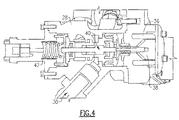
- FIG. 4 shows the turbine speed control valve assembly 28, which provides passive electrical proportional turbine speed control.
- the direct current power from the passive rectifier 34 is sent to a valve control solenoid 36.
- the solenoid 36 produces an electromagnetic force applied to a valve control solenoid plunger 38, which exerts an axial force that is proportional to the direct current power that is flowing in the windings of solenoid 36.
- the axial force produced by solenoid 36 is also proportional to the speed of the turbine 22. This axial force exerted by the plunger 38 pushes against a valve spool 40, which pushes against a valve opening spring 42.
- a linear motor or electromechanical actuator may be used to displace the valve spool 40.
- the axial force exerted by plunger 38 causes the valve spool 40 to shift to the left, compressing the valve opening spring 42 and decreasing the mass flow rate of the propellant entering the turbine 22 through the turbine inlet port 30.
- the solenoid 36 may stop providing an axial force to the valve spool 40.
- the spring 42 will decompress, causing the valve 28 to fully open, which allows the turbine 22 to accelerate to undesirable speeds.
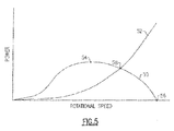
- Passive overspeed protection can be accomplished by designing the turbine 22 such that the peak efficiency of the turbine 22 occurs at a rotational speed that is below the peak power requirement of the centrifugal pump 24, as shown in Figure 5 .
- Curve 50 shows the power capability of turbine 22.
- Curve 52 shows the required power of the centrifugal pump 24.
- the peak efficiency point 54 of turbine power curve 50 shows the rotational speed at which the turbine 22 will produce the most power.
- efficiency of the turbine 22 is reduced due to incidence losses, blockage, and leakage. Incidence losses occur because the fluid incidence angle at an inlet of the turbine 22 causes an aerodynamic blockage in turbine blade passages, decreasing the efficiency of the turbine 22, and thus the output power of the turbine 22.
- At point 56 where the turbine efficiency drops to zero, the blades of the turbine 22 are completely stalled.
- the rotating group comprising turbine 22, centrifugal pump 24, shaft 26 and permanent magnet generator 32, will reach its maximum aerodynamic rotational speed 58.
- the peak efficiency 54 of the turbine 22 occurs at a lower rotational speed than the intersection 58.
- the peak efficiency 54 of the turbine 22 occurs at about 80,000 rpm, and the maximum aerodynamic rotational speed 58 of the rotating group is about 110,000 rpm.
- the design of the turbine 22 such that its peak efficiency 54 at a speed lower than a speed of the peak power requirement of the centrifugal pump 24 protects the TPA 20 from becoming damaged in the event of damage to the passive electrical proportional turbine speed control system.
- this design is accomplished by incorporating a feature into a disk of the turbine 22 that causes the turbine efficiency to decrease beyond a predetermined speed.
- an angle of attack in the turbine 22 is designed such that the turbine efficiency decreases beyond a predetermined speed.
- a chord length of a disk of turbine 22 is designed such that the turbine efficiency decreases beyond a predetermined speed.
- a disk of the turbine 22 is designed such that the blades deform (twist) at high speeds, thereby negatively altering the blade incidence angles.
- the turbine disk will deform due to a higher radial load, which decreases the efficiency of the turbine 22.
- centrifugal pump 24, permanent magnet generator 32 and shaft 26 are designed such that the rotating group operates at the maximum aerodynamic rotational speed 58.
Landscapes
- Engineering & Computer Science (AREA)
- Mechanical Engineering (AREA)
- General Engineering & Computer Science (AREA)
- Chemical & Material Sciences (AREA)
- Combustion & Propulsion (AREA)
- Control Of Turbines (AREA)
Abstract
Description
- This application relates to a turbine pump assembly, and more particularly to a passive overspeed controlled turbine pump assembly.
- Rockets are maneuvered by vectoring the rocket engine thrust direction. A thrust vector control system often relies on hydraulic rams to displace the engine nozzle angle. Such hydraulic rams require high pressure hydraulic fluid pumping systems, capable of providing very high flow rates. This hydraulic flow is typically generated by a Turbine Pump Assembly (TPA), which may be powered by a fluid propellant provided by the main engine turbo-pump assembly.
- A traditional TPA comprises a turbine and a hydraulic pump. Typically, the turbine operates at very high rotational speeds, such as 115,000 rpm, while the hydraulic pump operates at lower speeds, such as 6100 rpm. A gear reduction system is incorporated between the hydraulic pump and the turbine to accommodate the different operating speeds.
- A traditional TPA further includes a Turbine Speed Control Valve Assembly to control the fluid flowing to the turbine, and thus the turbine rotational speed. The output power of the turbine is proportional to the mass flow rate of the propellant through the valve. In traditional systems, this valve assembly comprises a spring and a fly weight governor assembly. As the turbine spins, the fly weight governor assembly also rotates. As the fly weight governor rotates, a centripetal force is applied to arms of the fly weight governor, proportional to the rotational speed of the turbine. When the turbine and fly weight governor reach a particular speed, the fly weight governor arms push against the spring, causing the valve to partially close. As the turbine spins faster, the valve is pushed further closed. When the turbine reaches a desired speed, the fly weight governor forces are balanced against the spring force, with the valve open just far enough to maintain the turbine speed.
- If additional load is applied to the TPA by the hydraulic system, the turbine will decelerate. When the turbine slows down, the centripetal force acting on the fly weight governor arms is reduced, allowing the spring to push the valve further open, allowing more propellant to flow into the turbine, causing the turbine to speed back up to the desired speed. This system is well developed, but also complex and expensive.
- A turbine pump assembly has a turbine, a centrifugal pump, and a passive electrical speed control system. The turbine has a peak efficiency at a first speed that is lower than a second speed at which the centrifugal pump is operating at a peak power requirement. A rocket thrust vector control system is also disclosed.
- The various features and advantages of this invention will become apparent to those skilled in the art from the following detailed description of an embodiment. The drawings that accompany the detailed description can be briefly described as follows.
-
-
Figure 1 shows a perspective view of a turbine pump assembly. -
Figure 2 shows a cross section of the turbine pump assembly ofFigure 1 . -
Figure 3 shows a partial view of a portion of the turbine pump assembly ofFigure 1 . -
Figure 4 shows a partial view of a portion of the turbine pump assembly ofFigure 1 . -
Figure 5 shows a graph of speed and power of the turbine pump assembly ofFigure 1 . - Referring to
Figure 1 , a turbine pump assembly (TPA)system 20 includes aturbine 22 and acentrifugal pump 24. The TPA 20 may be powered by a propellant, such as hydrogen gas, provided by the main engine turbo-pump assembly 29 (shown inFigure 2 ). Other propellants are contemplated, such as oxygen, methane, helium, or nitrogen, for example. Thecentrifugal pump 24 allows the TPA 20 to be much smaller than the traditional system that utilizes a hydraulic pump. - Both the
turbine 22 andcentrifugal pump 24 are capable of operating at very high speeds, and thus are configured to rotate on asingle shaft 26, as shown inFigure 2 . In one example, the operating speed of theturbine 22 andcentrifugal pump 24 is between 90,000 rpm and 140,000 rpm. Theturbine 22 drives thecentrifugal pump 24 through theshaft 26. Hydraulic fluid from thecentrifugal pump 24 is communicated to an engine nozzle 27 (shown schematically) to displace a rocket engine nozzle angle relative to a rocket core axis. The operation of theengine nozzle 27 and how the angle is adjusted are known. - Although disclosed as part of a rocket engine nozzle control, this disclosure may have application in other systems.
- Since the
turbine 22 andcentrifugal pump 24 both operate at high speeds, and thus can operate on thesame shaft 26, a gear reduction between theturbine 22 and thecentrifugal pump 24 is not required. This configuration results in fewer moving parts in the overall system than a traditional TPA. The higher speeds of thesingle shaft 26 also prohibit the use of the fly weight governor used in traditional systems. - A
speed control valve 28 controls the amount of propellant that goes to theturbine 22 from a main engine turbo-pump assembly 29 (shown schematically) through a turbinegas inlet port 30. When propellant is supplied to the turbinegas inlet port 30, propellant flows through thespeed control valve 28 and to theturbine 22, causing theturbine 22 to rotate. As the mass flow rate of the propellant increases, the speed of theturbine 22 will increase. Thespeed control valve 28 controls the speed of theturbine 22 by varying the mass flow rate of the propellant. -
Figure 3 shows the rotating components of theTPA 20. Agenerator 32 is arranged along theshaft 26 between theturbine 22 and thecentrifugal pump 24. In one embodiment, thegenerator 32 is a high speed permanent magnet generator. In the illustrated embodiment, thegenerator 32 comprisespermanent magnets 31 that rotate with theshaft 26, and generate a current in astationary coil 33. Thepermanent magnet generator 32 generates alternating current power proportional to the rotational speed of theturbine 22. This alternating current power is passively rectified by a passive rectifier 34 (shown inFigure 1 ) into direct current power proportional to the rotational speed of theturbine 22, which is then used to control the speed of theturbine 22. -
Figure 4 shows the turbine speedcontrol valve assembly 28, which provides passive electrical proportional turbine speed control. In the illustrated embodiment, the direct current power from thepassive rectifier 34 is sent to avalve control solenoid 36. Thesolenoid 36 produces an electromagnetic force applied to a valvecontrol solenoid plunger 38, which exerts an axial force that is proportional to the direct current power that is flowing in the windings ofsolenoid 36. Because the direct current power is proportional to the speed of theturbine 22, the axial force produced bysolenoid 36 is also proportional to the speed of theturbine 22. This axial force exerted by theplunger 38 pushes against avalve spool 40, which pushes against avalve opening spring 42. In another embodiment, a linear motor or electromechanical actuator may be used to displace thevalve spool 40. In the shown example, the axial force exerted byplunger 38 causes thevalve spool 40 to shift to the left, compressing thevalve opening spring 42 and decreasing the mass flow rate of the propellant entering theturbine 22 through theturbine inlet port 30. - As the
turbine 22 spins faster, more alternating current power is generated at thepermanent magnet generator 32, creating more direct current power rectified by thepassive rectifier 34. As direct current power in thevalve control solenoid 36 increases, the electromagnetic force applied to the valvecontrol solenoid plunger 38 increases. The increased electromagnetic force results in an increased axial force exerted by theplunger 38. The increased axial force exerted by theplunger 38 pushes thevalve spool 40, which pushes thespring 42 to push thevalve 28 further closed, which decreases the mass flow rate of propellant entering theturbine 22, thus decreasing the speed of theturbine 22. When theturbine 22 reaches a desired speed, the axial force generated by thevalve control solenoid 36 is balanced with the spring force ofspring 42, such that thevalve 28 is open just far enough to maintain a desired speed of theturbine 22. - As the speed of the
turbine 22 decreases, the electromagnetic force applied to the valvecontrol solenoid plunger 38 decreases, causing thevalve spool 40 to shift in the opposite direction, decompressing thevalve opening spring 42. When thevalve opening spring 42 is decompressed, the mass flow rate of propellant entering theturbine 22 through turbinegas inlet port 30 increases. The desired mass flow rate and turbine speed depend on the requirements of a particular system. Details of the passive electrical speed control system are found in co-pending United States Patent Application Serial No. __, entitled "Passive Electrical Proportional Turbine Speed Control System" filed on even date herewith. Details of a circuit breaker control valve are found in co-pending United States Patent Application Serial No. _, entitled "Pneumatic Circuit Breaker Based Self Resetting Passive Overspeed Control Valve for TPA" filed on even date herewith. - If the passive electrical proportional turbine speed control system becomes damaged, the
solenoid 36 may stop providing an axial force to thevalve spool 40. When no axial force is applied to thevalve spool 40, thespring 42 will decompress, causing thevalve 28 to fully open, which allows theturbine 22 to accelerate to undesirable speeds. - Passive overspeed protection can be accomplished by designing the
turbine 22 such that the peak efficiency of theturbine 22 occurs at a rotational speed that is below the peak power requirement of thecentrifugal pump 24, as shown inFigure 5 .Curve 50 shows the power capability ofturbine 22.Curve 52 shows the required power of thecentrifugal pump 24. The peak efficiency point 54 ofturbine power curve 50 shows the rotational speed at which theturbine 22 will produce the most power. As the rotational speed ofturbine 22 increases beyond the peak efficiency 54, efficiency of theturbine 22 is reduced due to incidence losses, blockage, and leakage. Incidence losses occur because the fluid incidence angle at an inlet of theturbine 22 causes an aerodynamic blockage in turbine blade passages, decreasing the efficiency of theturbine 22, and thus the output power of theturbine 22. Atpoint 56, where the turbine efficiency drops to zero, the blades of theturbine 22 are completely stalled. - As the speed of the
centrifugal pump 24 increases, its input power requirement increases. At the intersection ofcurves turbine 22,centrifugal pump 24,shaft 26 andpermanent magnet generator 32, will reach its maximum aerodynamicrotational speed 58. In one embodiment, the peak efficiency 54 of theturbine 22 occurs at a lower rotational speed than theintersection 58. In one embodiment, the peak efficiency 54 of theturbine 22 occurs at about 80,000 rpm, and the maximum aerodynamicrotational speed 58 of the rotating group is about 110,000 rpm. - The design of the
turbine 22 such that its peak efficiency 54 at a speed lower than a speed of the peak power requirement of thecentrifugal pump 24 protects theTPA 20 from becoming damaged in the event of damage to the passive electrical proportional turbine speed control system. In one embodiment, this design is accomplished by incorporating a feature into a disk of theturbine 22 that causes the turbine efficiency to decrease beyond a predetermined speed. In another embodiment, an angle of attack in theturbine 22 is designed such that the turbine efficiency decreases beyond a predetermined speed. In another embodiment, a chord length of a disk ofturbine 22 is designed such that the turbine efficiency decreases beyond a predetermined speed. In yet another embodiment, a disk of theturbine 22 is designed such that the blades deform (twist) at high speeds, thereby negatively altering the blade incidence angles. In this embodiment, as the speed of theturbine 22 increases beyond a predetermined speed, the turbine disk will deform due to a higher radial load, which decreases the efficiency of theturbine 22. - In further embodiments, the
centrifugal pump 24,permanent magnet generator 32 andshaft 26 are designed such that the rotating group operates at the maximum aerodynamicrotational speed 58. - Although the different examples have a specific component shown in the illustrations, embodiments of this disclosure are not limited to those particular combinations. It is possible to use some of the components or features from one of the examples in combination with features or components from another one of the examples.
- Furthermore, the foregoing description shall be interpreted as illustrative and not in any limiting sense. A worker of ordinary skill in the art would understand that certain modifications could come within the scope of this disclosure. For these reasons, the following claims should be studied to determine the true scope and content of this disclosure.
Claims (15)
- A turbine pump assembly (20), comprising:a turbine (22) having a peak efficiency at a first speed;a centrifugal pump (24);a passive electrical speed control system; andthe first speed is lower than a second speed at which the centrifugal pump (24) is operating at a peak power requirement.
- The turbine pump assembly of claims 1 or 2, wherein a disk of the turbine (22) is configured to deform when a rotational speed of the turbine exceeds the first speed.
- The turbine pump assembly of any preceding claim, wherein the turbine (22) drives the centrifugal pump (24).
- The turbine pump assembly of any preceding claim, wherein the turbine (22) and the centrifugal pump (24) rotate about a common shaft (26).
- The turbine pump assembly of claim 4, wherein the passive electrical speed control system comprises a generator (32) and a valve control solenoid (36).
- The turbine pump assembly of claim 5, wherein the generator (32) is arranged along the shaft (26) between the centrifugal pump (24) and the turbine (22).
- The turbine pump assembly of any preceding claim, wherein the turbine (22) is powered by a propellant provided by a main engine turbo-pump of a vehicle.
- The turbine pump assembly of claim 7, wherein the propellant is hydrogen gas.
- The turbine pump assembly of any preceding claim, wherein the passive electrical speed control system further comprises a valve (28) configured to meter a flow of propellant to the turbine.
- The turbine pump assembly of claim 9, wherein the passive electrical speed control system further comprises a valve control solenoid (36) configured to exert an axial force on the valve (28), such that the valve (28) meters the flow of propellant proportional to a speed of the turbine (22).
- A rocket thrust vector control system, comprising:an engine nozzle (27);the turbine pump assembly (20) of claim 1
- The rocket thrust vector control system as recited in claim 11, wherein a disk of the turbine (22) is configured to deform when a rotational speed of the turbine exceeds the first speed.
- The rocket thrust vector control system as recited in claims 11 or 12, wherein the turbine (22) drives the centrifugal pump (24).
- The rocket thrust vector control system as recited in any of claims 11-13, wherein the turbine (22) is powered by a propellant provided by a main engine turbo-pump of a vehicle.
- The rocket thrust vector control system as recited in any of claims 11-14, wherein the passive electrical speed control system, comprises a generator (32) and a valve control solenoid (36).
Applications Claiming Priority (1)
| Application Number | Priority Date | Filing Date | Title |
|---|---|---|---|
| US14/695,079 US10167732B2 (en) | 2015-04-24 | 2015-04-24 | Passive overspeed controlled turbo pump assembly |
Publications (2)
| Publication Number | Publication Date |
|---|---|
| EP3085941A1 true EP3085941A1 (en) | 2016-10-26 |
| EP3085941B1 EP3085941B1 (en) | 2018-02-28 |
Family
ID=55755500
Family Applications (1)
| Application Number | Title | Priority Date | Filing Date |
|---|---|---|---|
| EP16165713.5A Active EP3085941B1 (en) | 2015-04-24 | 2016-04-18 | Passive overspeed controlled turbo pump assembly and rocket thrust vector control system comprising such an assembly |
Country Status (2)
| Country | Link |
|---|---|
| US (1) | US10167732B2 (en) |
| EP (1) | EP3085941B1 (en) |
Cited By (2)
| Publication number | Priority date | Publication date | Assignee | Title |
|---|---|---|---|---|
| EP3672033A1 (en) * | 2018-12-21 | 2020-06-24 | ArianeGroup GmbH | Combination of an electric generator and a turbopump |
| EP3943739A1 (en) * | 2020-07-24 | 2022-01-26 | Hamilton Sundstrand Corporation | Turbine pump assembly with turbine exhaust cooled heat exchanger for active hydraulic oil |
Families Citing this family (6)
| Publication number | Priority date | Publication date | Assignee | Title |
|---|---|---|---|---|
| US20160312742A1 (en) * | 2015-04-24 | 2016-10-27 | Hamilton Sundstrand Corporation | Passive electrical proportional turbine speed control system |
| US10479525B2 (en) | 2018-04-03 | 2019-11-19 | Kidde Technologies, Inc. | Utilization of engine bleed air to provide extended duration emergency aircraft power |
| US11286886B2 (en) * | 2019-04-14 | 2022-03-29 | Hamilton Sundstrand Corporation | Distributed fuel modules with hydraulic flow circuit breakers and gaseous flow circuit breakers |
| US20220098995A1 (en) * | 2020-07-23 | 2022-03-31 | Williams International Co., L.L.C. | Gas-turbine-engine overspeed protection system |
| US11952944B1 (en) * | 2023-02-10 | 2024-04-09 | General Electric Company | Jet engine thermal transport bus pumps |
| CN117131710B (en) * | 2023-10-26 | 2024-03-19 | 江苏深蓝航天有限公司 | Vibration data processing method for liquid rocket engine test turbopump |
Citations (5)
| Publication number | Priority date | Publication date | Assignee | Title |
|---|---|---|---|---|
| GB191105990A (en) * | 1911-03-09 | 1911-08-31 | John Richardson | Improvements in Turbines. |
| US2707866A (en) * | 1949-04-27 | 1955-05-10 | Thompson Prod Inc | Jet engine fuel control system responsive to engine speed and tail pipe temperature |
| US5003772A (en) * | 1988-10-12 | 1991-04-02 | Sundstrand Corporation | Turbo hydraulic unitized actuator |
| US20080075595A1 (en) * | 2004-09-13 | 2008-03-27 | Gordon Proven | Cross Flow Twist Turbine |
| EP2682590A2 (en) * | 2012-07-03 | 2014-01-08 | Hamilton Sundstrand Corporation | Turbine generator assembly for thrust vector control |
Family Cites Families (16)
| Publication number | Priority date | Publication date | Assignee | Title |
|---|---|---|---|---|
| US3052252A (en) | 1956-01-30 | 1962-09-04 | Bendix Corp | Speed control system for turbine and liquid pressure supply device |
| US3078739A (en) | 1958-12-19 | 1963-02-26 | Voith Getriebe Kg | Transmission |
| US4073138A (en) * | 1974-05-28 | 1978-02-14 | Aerojet-General Corporation | Mixed mode rocket engine |
| US4309871A (en) * | 1977-11-01 | 1982-01-12 | Borg-Warner Corporation | Control apparatus for controlling surge in air compressor-driven system |
| US4165795A (en) | 1978-02-17 | 1979-08-28 | Gould Inc. | Hybrid automobile |
| US4334823A (en) * | 1980-12-16 | 1982-06-15 | Sharp Peter A | Wind or fluid current turbine |
| US4599044A (en) * | 1985-01-07 | 1986-07-08 | The United States Of America As Represented By The Secretary Of The Navy | Electronic feedback area control system for TVC gas generator |
| US4761187A (en) * | 1986-08-25 | 1988-08-02 | Rockwell International Corporation | Method of improving stress corrosion resistance of alloys |
| CN100335776C (en) * | 2002-02-25 | 2007-09-05 | 伊斯克拉风涡轮机有限公司 | Passive speed and power regulation for wind-driven turbine |
| FR2879720B1 (en) * | 2004-12-17 | 2007-04-06 | Snecma Moteurs Sa | COMPRESSION-EVAPORATION SYSTEM FOR LIQUEFIED GAS |
| US8418967B2 (en) | 2008-02-21 | 2013-04-16 | Cornerstone Research Group, Inc. | Passive adaptive structures |
| US8718831B2 (en) | 2008-05-09 | 2014-05-06 | General Electric Company | Methods and apparatus for sensing parameters of rotating blades |
| US8561403B2 (en) | 2008-08-05 | 2013-10-22 | Vandyne Super Turbo, Inc. | Super-turbocharger having a high speed traction drive and a continuously variable transmission |
| US8366057B2 (en) * | 2009-07-28 | 2013-02-05 | University Of Kansas | Method and apparatus for pressure adaptive morphing structure |
| US20130216378A1 (en) | 2012-02-16 | 2013-08-22 | Clipper Windpower, Llc | Passive Governor for Windpower Applications |
| GB201307610D0 (en) | 2013-04-26 | 2013-06-12 | Controlled Power Technologies Ltd | Exhaust Driven Turbine-Generator Integrated Gas Energy Recovery System |
-
2015
- 2015-04-24 US US14/695,079 patent/US10167732B2/en active Active
-
2016
- 2016-04-18 EP EP16165713.5A patent/EP3085941B1/en active Active
Patent Citations (5)
| Publication number | Priority date | Publication date | Assignee | Title |
|---|---|---|---|---|
| GB191105990A (en) * | 1911-03-09 | 1911-08-31 | John Richardson | Improvements in Turbines. |
| US2707866A (en) * | 1949-04-27 | 1955-05-10 | Thompson Prod Inc | Jet engine fuel control system responsive to engine speed and tail pipe temperature |
| US5003772A (en) * | 1988-10-12 | 1991-04-02 | Sundstrand Corporation | Turbo hydraulic unitized actuator |
| US20080075595A1 (en) * | 2004-09-13 | 2008-03-27 | Gordon Proven | Cross Flow Twist Turbine |
| EP2682590A2 (en) * | 2012-07-03 | 2014-01-08 | Hamilton Sundstrand Corporation | Turbine generator assembly for thrust vector control |
Cited By (3)
| Publication number | Priority date | Publication date | Assignee | Title |
|---|---|---|---|---|
| EP3672033A1 (en) * | 2018-12-21 | 2020-06-24 | ArianeGroup GmbH | Combination of an electric generator and a turbopump |
| EP3943739A1 (en) * | 2020-07-24 | 2022-01-26 | Hamilton Sundstrand Corporation | Turbine pump assembly with turbine exhaust cooled heat exchanger for active hydraulic oil |
| US11401892B2 (en) | 2020-07-24 | 2022-08-02 | Hamilton Sundstrand Corporation | Turbine pump assembly with turbine exhaust cooled heat exchanger for active hydraulic oil |
Also Published As
| Publication number | Publication date |
|---|---|
| EP3085941B1 (en) | 2018-02-28 |
| US10167732B2 (en) | 2019-01-01 |
| US20160312652A1 (en) | 2016-10-27 |
Similar Documents
| Publication | Publication Date | Title |
|---|---|---|
| EP3085941B1 (en) | Passive overspeed controlled turbo pump assembly and rocket thrust vector control system comprising such an assembly | |
| JP5681721B2 (en) | Adaptive core engine | |
| US10240613B2 (en) | Supersonic compressor with structural arrangement to increase pressure energy in a discharge process fluid received from a centrifugal impeller | |
| US20080175703A1 (en) | Electric turbine bypass fan and compressor for hybrid propulsion | |
| Xu et al. | Design of high specific speed mixed flow micro-compressor for co-flow jet actuators | |
| EP2484912B1 (en) | Wet gas compressor systems | |
| EP1900908A2 (en) | Variable geometry turbine | |
| EP3061975B1 (en) | Axial compressor with flow recirculation | |
| GB2541932A (en) | Gas turbine | |
| EP3569856A1 (en) | Electric ducted fan | |
| US20090232636A1 (en) | Multistage compressor for a gas turbine, comprising discharge ports and injection ports to stabilize the compressor flow | |
| US20160102679A1 (en) | Electromagnetic shaft-wheel coupling for arbitrary distribution of shaft torque in a turbine engine | |
| WO2016160393A1 (en) | Diffuser having multiple rows of diffuser vanes with different solidity | |
| US8800295B2 (en) | Device and a method for regulating a turbine engine, and an aircraft | |
| JP2012504210A (en) | In particular, a system for controlling a variable geometry device with a guide track connection, in particular for a gas turbine engine with a guide track connection | |
| US11286887B2 (en) | Pneumatic circuit breaker based self resetting passive overspeed control valve for turbine pump assembly | |
| JP5792387B2 (en) | Operation method of rotating machine | |
| US20160312742A1 (en) | Passive electrical proportional turbine speed control system | |
| JP2010526961A (en) | Control method of turbo compressor | |
| EP3757389B1 (en) | Motor cooling systems | |
| EP3808957B1 (en) | An electronic engine controller for a gas turbine engine configured to be connected to a solenoid valve | |
| EP1977082A2 (en) | Electric turbine bypass fan and compressor for hybrid propulsion | |
| JPS60178937A (en) | Improvement in acceleration of multi-axis gas turbine engine and gas turbine engine | |
| US9951683B2 (en) | Supplemental electromagnetic turbocharger actuator | |
| EP2636872B1 (en) | Turbomachine drive arrangement |
Legal Events
| Date | Code | Title | Description |
|---|---|---|---|
| PUAI | Public reference made under article 153(3) epc to a published international application that has entered the european phase |
Free format text: ORIGINAL CODE: 0009012 |
|
| AK | Designated contracting states |
Kind code of ref document: A1 Designated state(s): AL AT BE BG CH CY CZ DE DK EE ES FI FR GB GR HR HU IE IS IT LI LT LU LV MC MK MT NL NO PL PT RO RS SE SI SK SM TR |
|
| AX | Request for extension of the european patent |
Extension state: BA ME |
|
| STAA | Information on the status of an ep patent application or granted ep patent |
Free format text: STATUS: REQUEST FOR EXAMINATION WAS MADE |
|
| 17P | Request for examination filed |
Effective date: 20170425 |
|
| RBV | Designated contracting states (corrected) |
Designated state(s): AL AT BE BG CH CY CZ DE DK EE ES FI FR GB GR HR HU IE IS IT LI LT LU LV MC MK MT NL NO PL PT RO RS SE SI SK SM TR |
|
| GRAP | Despatch of communication of intention to grant a patent |
Free format text: ORIGINAL CODE: EPIDOSNIGR1 |
|
| STAA | Information on the status of an ep patent application or granted ep patent |
Free format text: STATUS: GRANT OF PATENT IS INTENDED |
|
| INTG | Intention to grant announced |
Effective date: 20170809 |
|
| GRAS | Grant fee paid |
Free format text: ORIGINAL CODE: EPIDOSNIGR3 |
|
| GRAJ | Information related to disapproval of communication of intention to grant by the applicant or resumption of examination proceedings by the epo deleted |
Free format text: ORIGINAL CODE: EPIDOSDIGR1 |
|
| GRAL | Information related to payment of fee for publishing/printing deleted |
Free format text: ORIGINAL CODE: EPIDOSDIGR3 |
|
| STAA | Information on the status of an ep patent application or granted ep patent |
Free format text: STATUS: REQUEST FOR EXAMINATION WAS MADE |
|
| GRAR | Information related to intention to grant a patent recorded |
Free format text: ORIGINAL CODE: EPIDOSNIGR71 |
|
| STAA | Information on the status of an ep patent application or granted ep patent |
Free format text: STATUS: GRANT OF PATENT IS INTENDED |
|
| GRAA | (expected) grant |
Free format text: ORIGINAL CODE: 0009210 |
|
| STAA | Information on the status of an ep patent application or granted ep patent |
Free format text: STATUS: THE PATENT HAS BEEN GRANTED |
|
| INTC | Intention to grant announced (deleted) | ||
| INTG | Intention to grant announced |
Effective date: 20180112 |
|
| AK | Designated contracting states |
Kind code of ref document: B1 Designated state(s): AL AT BE BG CH CY CZ DE DK EE ES FI FR GB GR HR HU IE IS IT LI LT LU LV MC MK MT NL NO PL PT RO RS SE SI SK SM TR |
|
| REG | Reference to a national code |
Ref country code: GB Ref legal event code: FG4D Ref country code: CH Ref legal event code: EP |
|
| REG | Reference to a national code |
Ref country code: AT Ref legal event code: REF Ref document number: 974422 Country of ref document: AT Kind code of ref document: T Effective date: 20180315 |
|
| REG | Reference to a national code |
Ref country code: IE Ref legal event code: FG4D |
|
| REG | Reference to a national code |
Ref country code: FR Ref legal event code: PLFP Year of fee payment: 3 |
|
| REG | Reference to a national code |
Ref country code: DE Ref legal event code: R096 Ref document number: 602016001689 Country of ref document: DE |
|
| REG | Reference to a national code |
Ref country code: NL Ref legal event code: MP Effective date: 20180228 |
|
| REG | Reference to a national code |
Ref country code: LT Ref legal event code: MG4D |
|
| REG | Reference to a national code |
Ref country code: AT Ref legal event code: MK05 Ref document number: 974422 Country of ref document: AT Kind code of ref document: T Effective date: 20180228 |
|
| PG25 | Lapsed in a contracting state [announced via postgrant information from national office to epo] |
Ref country code: FI Free format text: LAPSE BECAUSE OF FAILURE TO SUBMIT A TRANSLATION OF THE DESCRIPTION OR TO PAY THE FEE WITHIN THE PRESCRIBED TIME-LIMIT Effective date: 20180228 Ref country code: NO Free format text: LAPSE BECAUSE OF FAILURE TO SUBMIT A TRANSLATION OF THE DESCRIPTION OR TO PAY THE FEE WITHIN THE PRESCRIBED TIME-LIMIT Effective date: 20180528 Ref country code: HR Free format text: LAPSE BECAUSE OF FAILURE TO SUBMIT A TRANSLATION OF THE DESCRIPTION OR TO PAY THE FEE WITHIN THE PRESCRIBED TIME-LIMIT Effective date: 20180228 Ref country code: ES Free format text: LAPSE BECAUSE OF FAILURE TO SUBMIT A TRANSLATION OF THE DESCRIPTION OR TO PAY THE FEE WITHIN THE PRESCRIBED TIME-LIMIT Effective date: 20180228 Ref country code: LT Free format text: LAPSE BECAUSE OF FAILURE TO SUBMIT A TRANSLATION OF THE DESCRIPTION OR TO PAY THE FEE WITHIN THE PRESCRIBED TIME-LIMIT Effective date: 20180228 Ref country code: CY Free format text: LAPSE BECAUSE OF FAILURE TO SUBMIT A TRANSLATION OF THE DESCRIPTION OR TO PAY THE FEE WITHIN THE PRESCRIBED TIME-LIMIT Effective date: 20180228 Ref country code: NL Free format text: LAPSE BECAUSE OF FAILURE TO SUBMIT A TRANSLATION OF THE DESCRIPTION OR TO PAY THE FEE WITHIN THE PRESCRIBED TIME-LIMIT Effective date: 20180228 |
|
| PG25 | Lapsed in a contracting state [announced via postgrant information from national office to epo] |
Ref country code: GR Free format text: LAPSE BECAUSE OF FAILURE TO SUBMIT A TRANSLATION OF THE DESCRIPTION OR TO PAY THE FEE WITHIN THE PRESCRIBED TIME-LIMIT Effective date: 20180529 Ref country code: BG Free format text: LAPSE BECAUSE OF FAILURE TO SUBMIT A TRANSLATION OF THE DESCRIPTION OR TO PAY THE FEE WITHIN THE PRESCRIBED TIME-LIMIT Effective date: 20180528 Ref country code: SE Free format text: LAPSE BECAUSE OF FAILURE TO SUBMIT A TRANSLATION OF THE DESCRIPTION OR TO PAY THE FEE WITHIN THE PRESCRIBED TIME-LIMIT Effective date: 20180228 Ref country code: LV Free format text: LAPSE BECAUSE OF FAILURE TO SUBMIT A TRANSLATION OF THE DESCRIPTION OR TO PAY THE FEE WITHIN THE PRESCRIBED TIME-LIMIT Effective date: 20180228 Ref country code: RS Free format text: LAPSE BECAUSE OF FAILURE TO SUBMIT A TRANSLATION OF THE DESCRIPTION OR TO PAY THE FEE WITHIN THE PRESCRIBED TIME-LIMIT Effective date: 20180228 Ref country code: AT Free format text: LAPSE BECAUSE OF FAILURE TO SUBMIT A TRANSLATION OF THE DESCRIPTION OR TO PAY THE FEE WITHIN THE PRESCRIBED TIME-LIMIT Effective date: 20180228 |
|
| PG25 | Lapsed in a contracting state [announced via postgrant information from national office to epo] |
Ref country code: EE Free format text: LAPSE BECAUSE OF FAILURE TO SUBMIT A TRANSLATION OF THE DESCRIPTION OR TO PAY THE FEE WITHIN THE PRESCRIBED TIME-LIMIT Effective date: 20180228 Ref country code: IT Free format text: LAPSE BECAUSE OF FAILURE TO SUBMIT A TRANSLATION OF THE DESCRIPTION OR TO PAY THE FEE WITHIN THE PRESCRIBED TIME-LIMIT Effective date: 20180228 Ref country code: RO Free format text: LAPSE BECAUSE OF FAILURE TO SUBMIT A TRANSLATION OF THE DESCRIPTION OR TO PAY THE FEE WITHIN THE PRESCRIBED TIME-LIMIT Effective date: 20180228 Ref country code: AL Free format text: LAPSE BECAUSE OF FAILURE TO SUBMIT A TRANSLATION OF THE DESCRIPTION OR TO PAY THE FEE WITHIN THE PRESCRIBED TIME-LIMIT Effective date: 20180228 Ref country code: PL Free format text: LAPSE BECAUSE OF FAILURE TO SUBMIT A TRANSLATION OF THE DESCRIPTION OR TO PAY THE FEE WITHIN THE PRESCRIBED TIME-LIMIT Effective date: 20180228 |
|
| REG | Reference to a national code |
Ref country code: DE Ref legal event code: R097 Ref document number: 602016001689 Country of ref document: DE |
|
| PG25 | Lapsed in a contracting state [announced via postgrant information from national office to epo] |
Ref country code: CZ Free format text: LAPSE BECAUSE OF FAILURE TO SUBMIT A TRANSLATION OF THE DESCRIPTION OR TO PAY THE FEE WITHIN THE PRESCRIBED TIME-LIMIT Effective date: 20180228 Ref country code: SK Free format text: LAPSE BECAUSE OF FAILURE TO SUBMIT A TRANSLATION OF THE DESCRIPTION OR TO PAY THE FEE WITHIN THE PRESCRIBED TIME-LIMIT Effective date: 20180228 Ref country code: MC Free format text: LAPSE BECAUSE OF FAILURE TO SUBMIT A TRANSLATION OF THE DESCRIPTION OR TO PAY THE FEE WITHIN THE PRESCRIBED TIME-LIMIT Effective date: 20180228 Ref country code: DK Free format text: LAPSE BECAUSE OF FAILURE TO SUBMIT A TRANSLATION OF THE DESCRIPTION OR TO PAY THE FEE WITHIN THE PRESCRIBED TIME-LIMIT Effective date: 20180228 Ref country code: SM Free format text: LAPSE BECAUSE OF FAILURE TO SUBMIT A TRANSLATION OF THE DESCRIPTION OR TO PAY THE FEE WITHIN THE PRESCRIBED TIME-LIMIT Effective date: 20180228 |
|
| REG | Reference to a national code |
Ref country code: BE Ref legal event code: MM Effective date: 20180430 |
|
| PLBE | No opposition filed within time limit |
Free format text: ORIGINAL CODE: 0009261 |
|
| STAA | Information on the status of an ep patent application or granted ep patent |
Free format text: STATUS: NO OPPOSITION FILED WITHIN TIME LIMIT |
|
| REG | Reference to a national code |
Ref country code: IE Ref legal event code: MM4A |
|
| PG25 | Lapsed in a contracting state [announced via postgrant information from national office to epo] |
Ref country code: LU Free format text: LAPSE BECAUSE OF NON-PAYMENT OF DUE FEES Effective date: 20180418 |
|
| 26N | No opposition filed |
Effective date: 20181129 |
|
| PG25 | Lapsed in a contracting state [announced via postgrant information from national office to epo] |
Ref country code: SI Free format text: LAPSE BECAUSE OF FAILURE TO SUBMIT A TRANSLATION OF THE DESCRIPTION OR TO PAY THE FEE WITHIN THE PRESCRIBED TIME-LIMIT Effective date: 20180228 Ref country code: BE Free format text: LAPSE BECAUSE OF NON-PAYMENT OF DUE FEES Effective date: 20180430 |
|
| PG25 | Lapsed in a contracting state [announced via postgrant information from national office to epo] |
Ref country code: IE Free format text: LAPSE BECAUSE OF NON-PAYMENT OF DUE FEES Effective date: 20180418 |
|
| REG | Reference to a national code |
Ref country code: CH Ref legal event code: PL |
|
| PG25 | Lapsed in a contracting state [announced via postgrant information from national office to epo] |
Ref country code: MT Free format text: LAPSE BECAUSE OF NON-PAYMENT OF DUE FEES Effective date: 20180418 Ref country code: CH Free format text: LAPSE BECAUSE OF NON-PAYMENT OF DUE FEES Effective date: 20190430 Ref country code: LI Free format text: LAPSE BECAUSE OF NON-PAYMENT OF DUE FEES Effective date: 20190430 |
|
| PG25 | Lapsed in a contracting state [announced via postgrant information from national office to epo] |
Ref country code: TR Free format text: LAPSE BECAUSE OF FAILURE TO SUBMIT A TRANSLATION OF THE DESCRIPTION OR TO PAY THE FEE WITHIN THE PRESCRIBED TIME-LIMIT Effective date: 20180228 |
|
| PG25 | Lapsed in a contracting state [announced via postgrant information from national office to epo] |
Ref country code: PT Free format text: LAPSE BECAUSE OF FAILURE TO SUBMIT A TRANSLATION OF THE DESCRIPTION OR TO PAY THE FEE WITHIN THE PRESCRIBED TIME-LIMIT Effective date: 20180228 |
|
| PG25 | Lapsed in a contracting state [announced via postgrant information from national office to epo] |
Ref country code: MK Free format text: LAPSE BECAUSE OF NON-PAYMENT OF DUE FEES Effective date: 20180228 Ref country code: HU Free format text: LAPSE BECAUSE OF FAILURE TO SUBMIT A TRANSLATION OF THE DESCRIPTION OR TO PAY THE FEE WITHIN THE PRESCRIBED TIME-LIMIT; INVALID AB INITIO Effective date: 20160418 |
|
| PG25 | Lapsed in a contracting state [announced via postgrant information from national office to epo] |
Ref country code: IS Free format text: LAPSE BECAUSE OF FAILURE TO SUBMIT A TRANSLATION OF THE DESCRIPTION OR TO PAY THE FEE WITHIN THE PRESCRIBED TIME-LIMIT Effective date: 20180628 |
|
| P01 | Opt-out of the competence of the unified patent court (upc) registered |
Effective date: 20230522 |
|
| PGFP | Annual fee paid to national office [announced via postgrant information from national office to epo] |
Ref country code: DE Payment date: 20250319 Year of fee payment: 10 |
|
| PGFP | Annual fee paid to national office [announced via postgrant information from national office to epo] |
Ref country code: GB Payment date: 20260319 Year of fee payment: 11 |
|
| PGFP | Annual fee paid to national office [announced via postgrant information from national office to epo] |
Ref country code: FR Payment date: 20260319 Year of fee payment: 11 |