EP1900908A2 - Variable geometry turbine - Google Patents
Variable geometry turbine Download PDFInfo
- Publication number
- EP1900908A2 EP1900908A2 EP07116130A EP07116130A EP1900908A2 EP 1900908 A2 EP1900908 A2 EP 1900908A2 EP 07116130 A EP07116130 A EP 07116130A EP 07116130 A EP07116130 A EP 07116130A EP 1900908 A2 EP1900908 A2 EP 1900908A2
- Authority
- EP
- European Patent Office
- Prior art keywords
- turbine
- nozzle
- nozzle gap
- fluid
- turbine according
- Prior art date
- Legal status (The legal status is an assumption and is not a legal conclusion. Google has not performed a legal analysis and makes no representation as to the accuracy of the status listed.)
- Granted
Links
Images


Classifications
-
- F—MECHANICAL ENGINEERING; LIGHTING; HEATING; WEAPONS; BLASTING
- F01—MACHINES OR ENGINES IN GENERAL; ENGINE PLANTS IN GENERAL; STEAM ENGINES
- F01D—NON-POSITIVE DISPLACEMENT MACHINES OR ENGINES, e.g. STEAM TURBINES
- F01D17/00—Regulating or controlling by varying flow
- F01D17/10—Final actuators
- F01D17/12—Final actuators arranged in stator parts
- F01D17/14—Final actuators arranged in stator parts varying effective cross-sectional area of nozzles or guide conduits
- F01D17/141—Final actuators arranged in stator parts varying effective cross-sectional area of nozzles or guide conduits by means of shiftable members or valves obturating part of the flow path
- F01D17/143—Final actuators arranged in stator parts varying effective cross-sectional area of nozzles or guide conduits by means of shiftable members or valves obturating part of the flow path the shiftable member being a wall, or part thereof of a radial diffuser
-
- F—MECHANICAL ENGINEERING; LIGHTING; HEATING; WEAPONS; BLASTING
- F02—COMBUSTION ENGINES; HOT-GAS OR COMBUSTION-PRODUCT ENGINE PLANTS
- F02C—GAS-TURBINE PLANTS; AIR INTAKES FOR JET-PROPULSION PLANTS; CONTROLLING FUEL SUPPLY IN AIR-BREATHING JET-PROPULSION PLANTS
- F02C6/00—Plural gas-turbine plants; Combinations of gas-turbine plants with other apparatus; Adaptations of gas- turbine plants for special use
- F02C6/04—Gas-turbine plants providing heated or pressurised working fluid for other apparatus, e.g. without mechanical power output
- F02C6/10—Gas-turbine plants providing heated or pressurised working fluid for other apparatus, e.g. without mechanical power output supplying working fluid to a user, e.g. a chemical process, which returns working fluid to a turbine of the plant
- F02C6/12—Turbochargers, i.e. plants for augmenting mechanical power output of internal-combustion piston engines by increase of charge pressure
-
- F—MECHANICAL ENGINEERING; LIGHTING; HEATING; WEAPONS; BLASTING
- F05—INDEXING SCHEMES RELATING TO ENGINES OR PUMPS IN VARIOUS SUBCLASSES OF CLASSES F01-F04
- F05D—INDEXING SCHEME FOR ASPECTS RELATING TO NON-POSITIVE-DISPLACEMENT MACHINES OR ENGINES, GAS-TURBINES OR JET-PROPULSION PLANTS
- F05D2220/00—Application
- F05D2220/40—Application in turbochargers
-
- F—MECHANICAL ENGINEERING; LIGHTING; HEATING; WEAPONS; BLASTING
- F05—INDEXING SCHEMES RELATING TO ENGINES OR PUMPS IN VARIOUS SUBCLASSES OF CLASSES F01-F04
- F05D—INDEXING SCHEME FOR ASPECTS RELATING TO NON-POSITIVE-DISPLACEMENT MACHINES OR ENGINES, GAS-TURBINES OR JET-PROPULSION PLANTS
- F05D2250/00—Geometry
- F05D2250/10—Two-dimensional
- F05D2250/14—Two-dimensional elliptical
-
- F—MECHANICAL ENGINEERING; LIGHTING; HEATING; WEAPONS; BLASTING
- F05—INDEXING SCHEMES RELATING TO ENGINES OR PUMPS IN VARIOUS SUBCLASSES OF CLASSES F01-F04
- F05D—INDEXING SCHEME FOR ASPECTS RELATING TO NON-POSITIVE-DISPLACEMENT MACHINES OR ENGINES, GAS-TURBINES OR JET-PROPULSION PLANTS
- F05D2250/00—Geometry
- F05D2250/10—Two-dimensional
- F05D2250/16—Two-dimensional parabolic
-
- F—MECHANICAL ENGINEERING; LIGHTING; HEATING; WEAPONS; BLASTING
- F05—INDEXING SCHEMES RELATING TO ENGINES OR PUMPS IN VARIOUS SUBCLASSES OF CLASSES F01-F04
- F05D—INDEXING SCHEME FOR ASPECTS RELATING TO NON-POSITIVE-DISPLACEMENT MACHINES OR ENGINES, GAS-TURBINES OR JET-PROPULSION PLANTS
- F05D2250/00—Geometry
- F05D2250/10—Two-dimensional
- F05D2250/19—Two-dimensional machined; miscellaneous
- F05D2250/192—Two-dimensional machined; miscellaneous bevelled
-
- F—MECHANICAL ENGINEERING; LIGHTING; HEATING; WEAPONS; BLASTING
- F05—INDEXING SCHEMES RELATING TO ENGINES OR PUMPS IN VARIOUS SUBCLASSES OF CLASSES F01-F04
- F05D—INDEXING SCHEME FOR ASPECTS RELATING TO NON-POSITIVE-DISPLACEMENT MACHINES OR ENGINES, GAS-TURBINES OR JET-PROPULSION PLANTS
- F05D2250/00—Geometry
- F05D2250/10—Two-dimensional
- F05D2250/19—Two-dimensional machined; miscellaneous
- F05D2250/193—Two-dimensional machined; miscellaneous milled
-
- F—MECHANICAL ENGINEERING; LIGHTING; HEATING; WEAPONS; BLASTING
- F05—INDEXING SCHEMES RELATING TO ENGINES OR PUMPS IN VARIOUS SUBCLASSES OF CLASSES F01-F04
- F05D—INDEXING SCHEME FOR ASPECTS RELATING TO NON-POSITIVE-DISPLACEMENT MACHINES OR ENGINES, GAS-TURBINES OR JET-PROPULSION PLANTS
- F05D2250/00—Geometry
- F05D2250/60—Structure; Surface texture
- F05D2250/62—Structure; Surface texture smooth or fine
-
- F—MECHANICAL ENGINEERING; LIGHTING; HEATING; WEAPONS; BLASTING
- F05—INDEXING SCHEMES RELATING TO ENGINES OR PUMPS IN VARIOUS SUBCLASSES OF CLASSES F01-F04
- F05D—INDEXING SCHEME FOR ASPECTS RELATING TO NON-POSITIVE-DISPLACEMENT MACHINES OR ENGINES, GAS-TURBINES OR JET-PROPULSION PLANTS
- F05D2250/00—Geometry
- F05D2250/70—Shape
- F05D2250/71—Shape curved
-
- F—MECHANICAL ENGINEERING; LIGHTING; HEATING; WEAPONS; BLASTING
- F05—INDEXING SCHEMES RELATING TO ENGINES OR PUMPS IN VARIOUS SUBCLASSES OF CLASSES F01-F04
- F05D—INDEXING SCHEME FOR ASPECTS RELATING TO NON-POSITIVE-DISPLACEMENT MACHINES OR ENGINES, GAS-TURBINES OR JET-PROPULSION PLANTS
- F05D2260/00—Function
- F05D2260/96—Preventing, counteracting or reducing vibration or noise
Definitions
- the present invention concerns a variable geometry turbine, in particular for a turbocharger for a supercharged internal combustion engine, and said turbocharger and engine.
- VGT variable geometry turbines
- Known variable geometry turbines have a drive fluid inlet in form of a scroll surrounding the turbine rotor, and a vaned annular nozzle located between said inlet scroll and the turbine rotor.
- the nozzle gap is axially adjustable to control the power of the turbine and, in case of VGT turbochargers for supercharged internal combustion engines, the back pressure at the exhaust manifold of the engine (this is particularly useful when used as exhaust brake).
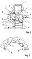
- Figure 1 shows a typical "moving wall” VGT.
- the figure represents a longitudinal section, according to a plane containing the axis 10 of the turbine rotor 4 (shown not sectioned).
- the fluid inlet scroll is designated by 1.
- the annular nozzle gap allowing the fluid flowing from the inlet scroll to the turbine rotor is designated by 3, a vane of the nozzle by 7.
- the vanes are fixed to the axially adjustable ring 5, apt to translate in the direction of the arrow A. The movement in one direction reduces the nozzle gap, the movement in the opposite direction increases it.
- a pierced shroud 8 with slots corresponding to the shape of the vane grid can be foreseen to prevent the fluid flow bypassing the nozzle gap.
- a configuration can be provided featuring a fixed vane grid on the wall opposite to the axially adjustable ring, and the axially adjustable ring featuring slots to accommodate the vanes.
- the adjustable ring can be configured as an annular piston, being housed inside an annular chamber 12, able to move out and to extend into the nozzle gap; sealing means 13, such as an outer and an inner sealing ring, are placed between the adjustable ring and the chamber walls.
- the actuator can be pneumatic, hydraulic, or electric, possibly comprising reset springs, and may be placed inside or external to the VGT housings. It can act, for example, through rods (not shown) extending along the direction of movement of the axially adjustable ring, said rods attached to the ring 5 on the side facing the annular chamber 12.
- the rods (or any similar guide system) may prevent rotation of the adjustable ring around axis 10, which would be caused by fluid forces against the inclined vanes.
- the actuator must hold the resetting force exerted by the fluid pressure onto the axially adjustable ring, which can be of considerable magnitude.
- balance holes 6 are commonly provided on the axial wall of the adjustable ring, normally one hole for each fluid passage between two consecutive vanes, as shown in figure 2, in order to balance the pressure between the nozzle gap 3 and the chamber 12.
- the size of the balance holes must be matched to allow proper transmission of the exhaust pressure waves generated by reciprocating engines, such as standard internal combustion engines.
- the pressure waves otherwise could generate vibration wear on the whole VGT actuating mechanism, and on other members such as seals and bushings.
- the pressure waves can provoke significant oscillation of the actuating mechanism, at least with certain types of actuators, in particular pneumatic and electric ones.
- the size of the balance holes has to be relatively large, their diameter may reach up to 90% of the fluid passage width. This includes the disadvantage that the balance holes cause considerable disturbance to the fluid flow through the nozzle gap. Reducing the nozzle gap, respectively narrowing the fluid passage between consecutive vanes, increases the interference of the holes with the fluid flow.
- the remaining flow area in the nozzle gap becomes less than the total area of the balance hole array.
- the balance holes represent significant sinks for the flow, leading to a expansion of the fluid flow into the holes, in turn the downstream edges of the balance holes become fluid-dynamical significant obstacles.
- the balance holes are machined or laser cut, and have (in fluid-dynamical view) relatively sharp edges, although a small countersink may be provided in order to remove burrs.
- the downstream portion of such balance hole edges therefore can provoke flow separation, leading to an undesirable pressure drop in the flow passage downstream the hole, and thus to a reduction in the resetting force exerted onto the adjustable ring.
- This effect becomes most obvious at small nozzle gaps and choke flow condition, where sonic speed is reached in the nozzle gap. In said condition, the resultant resetting force acting onto the axially adjustable ring can drop sharply, and can end up in reversed force direction.
- the problems exposed above have been solved by applying a generous rounding on the downstream edges of the balance holes, at the balance hole muzzles facing the fluid flow.
- the turbine is a gas turbine, and is in particular a turbine of a turbocharger for a supercharged internal combustion engine, said turbocharger and engine being further aspects of the invention.
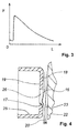
- FIG. 4 shows a detail section according to a plane parallel with the flow lines of the fluid through the nozzle gap (depending on the inclination of the vanes) of a VGT according to the present invention; the axially adjustable ring 25 is shown at minimum nozzle gap, and the flow from the inlet scroll to the turbine rotor is schematically indicated by the arrows 20.
- a balance hole 26 is provided in wall 19, whose surface 18 faces the nozzle gap 23. The edge 16, delimiting the hole 26 from the surface 18 presents a rounded portion, downstream the hole with respect to the fluid flow.
- not all of the edge is rounded off, nor is the rounding curvature deploying uniformly.
- the curvature radius of the edge can gradually vary from 0 (sharp edge) or from a minimum in the less concerned areas, to a maximum for example in the zone downstream with respect to the centre of the hole. This results in a shape of the rounded zone extended in the direction of the fluid flow.
- FIG 5 a partial view of the ring surface 18 facing the nozzle gap 23 is shown. There are shown the vanes 27 and the balance holes 26 with the rounded portion 17 and that the arrow 20 indicates the direction of the fluid. The vanes delimit a series of passages 14.
- a hole 26 is provided for each passage 14, centrally positioned with respect to the two vanes delimiting the passage.
- the rounded portion can form, with the surface 19, a border 15 whose shape can depend on how the rounding is performed along the edge (for example a parabolic or elliptic shape).
- the curvature radius R in the edge portion where it is at its maximum value, must be greater than 20% of the maximum width S of the hole (without taking the rounding off in account) in the mean fluid flow direction across the area of the hole, in order to achieve useful results.
- dimension S can substantially be the diameter of the hole, when it has circular section.
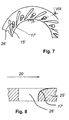
- Figures 7 and 8 show a preferred embodiment with a generous rounding 17', extending the border 15' downstream.
- the balance holes can have a circular section or another shape. Independently, they can have internal walls (without considering the rounded area) that are perpendicular or inclined with respect to the wall of the adjustable ring. According to a possible embodiment, the internal walls can be to some extent inclined in the direction and in the sense of the fluid flow. This further improves the resetting characteristics.
- Figure 9 and 10 show a nozzle ring with inclined holes having a non circular section.
- the holes can be produced by any suitable known technology, as well as the rounding off. They can be made, for example, by three axis milling, using radius or torus cutters having a diameter that is equal or slightly smaller than that of the balance hole.
- the adjustable ring can be vaned, or can have slots apt to receive the vanes of an opposed fixed vane grid. All the solutions commonly applied on VGT's of the "moving wall” type can be adopted, with the appropriate changes.
- the adjustable ring can be operated by various types of actuators, as discussed above.
- the position of the balance holes on the ring and their dimension can be chosen, as already happens for the prior art, according to the desired pressure in the chamber behind the ring, bearing in mind that, along the nozzle, the static pressure is higher towards the inlet scroll and lower towards the turbine rotor.
- the holes can have a diameter (for example) of 50 - 90% of the concerned vane passage width, or equivalent dimensions in case of a non-circular section.
- the VGT according to the present invention brings considerable advantages. The sharp pressure drop provoked by the interference of the holes at very small nozzle gaps, is avoided. In figure 11, the trend of the resetting force as a function of the nozzle gap in a VGT according to the present invention is schematically shown.
- a further advantage is the reduction in fluid pressure loss across the nozzle, resulting in higher efficiency of the turbine when recovering energy from fluid discharge.
Abstract
Description
- The present invention concerns a variable geometry turbine, in particular for a turbocharger for a supercharged internal combustion engine, and said turbocharger and engine.
- Known variable geometry turbines (VGT) have a drive fluid inlet in form of a scroll surrounding the turbine rotor, and a vaned annular nozzle located between said inlet scroll and the turbine rotor. On VGT's of the "moving wall" type, the nozzle gap is axially adjustable to control the power of the turbine and, in case of VGT turbochargers for supercharged internal combustion engines, the back pressure at the exhaust manifold of the engine (this is particularly useful when used as exhaust brake).
- Figure 1 shows a typical "moving wall" VGT. The figure represents a longitudinal section, according to a plane containing the
axis 10 of the turbine rotor 4 (shown not sectioned). The fluid inlet scroll is designated by 1. The annular nozzle gap allowing the fluid flowing from the inlet scroll to the turbine rotor is designated by 3, a vane of the nozzle by 7. The vanes are fixed to the axiallyadjustable ring 5, apt to translate in the direction of the arrow A. The movement in one direction reduces the nozzle gap, the movement in the opposite direction increases it. When the adjustable ring is moved in the closing direction, the vane grid is received into theannular hollow 11 provided in theturbine housing 2; apierced shroud 8 with slots corresponding to the shape of the vane grid can be foreseen to prevent the fluid flow bypassing the nozzle gap. Alternatively, a configuration can be provided featuring a fixed vane grid on the wall opposite to the axially adjustable ring, and the axially adjustable ring featuring slots to accommodate the vanes. The adjustable ring can be configured as an annular piston, being housed inside anannular chamber 12, able to move out and to extend into the nozzle gap; sealing means 13, such as an outer and an inner sealing ring, are placed between the adjustable ring and the chamber walls. An actuating system (not shown) is provided to control the axial position of the adjustable ring according to the requirements. The actuator can be pneumatic, hydraulic, or electric, possibly comprising reset springs, and may be placed inside or external to the VGT housings. It can act, for example, through rods (not shown) extending along the direction of movement of the axially adjustable ring, said rods attached to thering 5 on the side facing theannular chamber 12. The rods (or any similar guide system) may prevent rotation of the adjustable ring aroundaxis 10, which would be caused by fluid forces against the inclined vanes. The actuator must hold the resetting force exerted by the fluid pressure onto the axially adjustable ring, which can be of considerable magnitude. In order to reduce the resetting load onto actuator and actuating mechanism,balance holes 6 are commonly provided on the axial wall of the adjustable ring, normally one hole for each fluid passage between two consecutive vanes, as shown in figure 2, in order to balance the pressure between thenozzle gap 3 and thechamber 12. - On exhaust gas driven turbines, the size of the balance holes must be matched to allow proper transmission of the exhaust pressure waves generated by reciprocating engines, such as standard internal combustion engines. The pressure waves otherwise could generate vibration wear on the whole VGT actuating mechanism, and on other members such as seals and bushings. Moreover, the pressure waves can provoke significant oscillation of the actuating mechanism, at least with certain types of actuators, in particular pneumatic and electric ones. To keep vibration and oscillation on an acceptable level, the size of the balance holes has to be relatively large, their diameter may reach up to 90% of the fluid passage width. This includes the disadvantage that the balance holes cause considerable disturbance to the fluid flow through the nozzle gap. Reducing the nozzle gap, respectively narrowing the fluid passage between consecutive vanes, increases the interference of the holes with the fluid flow. At very narrow nozzle gaps, the remaining flow area in the nozzle gap becomes less than the total area of the balance hole array. In such condition, the balance holes represent significant sinks for the flow, leading to a expansion of the fluid flow into the holes, in turn the downstream edges of the balance holes become fluid-dynamical significant obstacles.
- On known pressure balance arrays, the balance holes are machined or laser cut, and have (in fluid-dynamical view) relatively sharp edges, although a small countersink may be provided in order to remove burrs. The downstream portion of such balance hole edges therefore can provoke flow separation, leading to an undesirable pressure drop in the flow passage downstream the hole, and thus to a reduction in the resetting force exerted onto the adjustable ring. This effect becomes most obvious at small nozzle gaps and choke flow condition, where sonic speed is reached in the nozzle gap. In said condition, the resultant resetting force acting onto the axially adjustable ring can drop sharply, and can end up in reversed force direction.
- In figure 3 the resetting force F (in ordinate) typically acting on the adjustable ring, and from there on the whole actuating mechanism, is qualitatively represented as a function of the nozzle gap L (in abscissa). As the nozzle gap decreases, a gradual increase of the resetting force is observed for almost the whole adjustable range, while at a narrow nozzle gap the force collapses due to the interference of the holes with the fluid flow. Safe control of the variable geometry nozzle at such small nozzle gaps thus becomes impossible, limiting the minimum admissible nozzle gap to values much higher than those that would be desirable under particular operation conditions. Generally speaking the control of known systems is unsatisfactory at small nozzle gaps. The turbo brake power (engine brake power) of VGT-supercharged vehicle engines is therefore limited, as well as engine response in transient operation conditions.
- According to the present invention, the problems exposed above have been solved by applying a generous rounding on the downstream edges of the balance holes, at the balance hole muzzles facing the fluid flow.
- According to a preferred embodiment of the invention, the turbine is a gas turbine, and is in particular a turbine of a turbocharger for a supercharged internal combustion engine, said turbocharger and engine being further aspects of the invention.
- The present invention will now be illustrated by a detailed description of preferred, but not limiting, embodiments, given for example purpose, with the help of the enclosed figures whereof :
- figure 1, already discussed above, shows a longitudinal section view of a VGT according to the prior art;
- figure 2, already discussed above, schematically shows a plane view from the nozzle gap onto the axially adjustable ring of the VGT of figure 1;
- figure 3, already discussed above, schematically shows the resetting force exerted onto the axially adjustable ring as a function of the nozzle gap in a VGT having an axially adjustable ring provided with balance holes according to prior art;
- figure 4 schematically shows a section view of an axially adjustable ring of a VGT according to the present invention;
- figure 5 schematically shows a plane view from the nozzle gap onto the axially adjustable ring of a VGT according to the present invention;
- figure 6 schematically shows the section view VI - VI of the adjustable ring of figure 5;
- figure 7 schematically shows a plane view from the nozzle gap onto an axially adjustable ring of a VGT according to another aspect of the present invention;
- figure 8 schematically shows the section view VIII-VIII of the adjustable ring of figure 7;
- figure 9 schematically shows a plane view from the nozzle gap onto an axially adjustable ring of a VGT according to a further aspect of the present invention;
- figure 10 schematically shows section view X - X view of the axially adjustable ring in figure 9;
- figure 11 schematically shows the resetting force exerted onto the axially adjustable ring as a function of the nozzle gap in a VGT according to the present invention.
- The VGT according to the present invention can be designed and manufactured in a similar way as the one of prior art described above, except for the shape of the balance hole muzzles. Figure 4 shows a detail section according to a plane parallel with the flow lines of the fluid through the nozzle gap (depending on the inclination of the vanes) of a VGT according to the present invention; the axially
adjustable ring 25 is shown at minimum nozzle gap, and the flow from the inlet scroll to the turbine rotor is schematically indicated by thearrows 20. Abalance hole 26 is provided inwall 19, whosesurface 18 faces thenozzle gap 23. Theedge 16, delimiting thehole 26 from thesurface 18 presents a rounded portion, downstream the hole with respect to the fluid flow. - According to a preferred embodiment not all of the edge is rounded off, nor is the rounding curvature deploying uniformly. The curvature radius of the edge can gradually vary from 0 (sharp edge) or from a minimum in the less concerned areas, to a maximum for example in the zone downstream with respect to the centre of the hole. This results in a shape of the rounded zone extended in the direction of the fluid flow. In figure 5 a partial view of the
ring surface 18 facing thenozzle gap 23 is shown. There are shown thevanes 27 and thebalance holes 26 with therounded portion 17 and that thearrow 20 indicates the direction of the fluid. The vanes delimit a series ofpassages 14. According to a preferred embodiment, ahole 26 is provided for eachpassage 14, centrally positioned with respect to the two vanes delimiting the passage. The rounded portion can form, with thesurface 19, aborder 15 whose shape can depend on how the rounding is performed along the edge (for example a parabolic or elliptic shape). - It has been discovered that the curvature radius R, in the edge portion where it is at its maximum value, must be greater than 20% of the maximum width S of the hole (without taking the rounding off in account) in the mean fluid flow direction across the area of the hole, in order to achieve useful results. With reference to figure 6, showing section VI - VI of fig 5, it can be appreciated that dimension S can substantially be the diameter of the hole, when it has circular section. Figures 7 and 8 show a preferred embodiment with a generous rounding 17', extending the border 15' downstream. The balance holes can have a circular section or another shape. Independently, they can have internal walls (without considering the rounded area) that are perpendicular or inclined with respect to the wall of the adjustable ring. According to a possible embodiment, the internal walls can be to some extent inclined in the direction and in the sense of the fluid flow. This further improves the resetting characteristics. Figure 9 and 10 show a nozzle ring with inclined holes having a non circular section.
- The holes can be produced by any suitable known technology, as well as the rounding off. They can be made, for example, by three axis milling, using radius or torus cutters having a diameter that is equal or slightly smaller than that of the balance hole.
- As in the prior art, the adjustable ring can be vaned, or can have slots apt to receive the vanes of an opposed fixed vane grid. All the solutions commonly applied on VGT's of the "moving wall" type can be adopted, with the appropriate changes. The adjustable ring can be operated by various types of actuators, as discussed above.
- The position of the balance holes on the ring and their dimension can be chosen, as already happens for the prior art, according to the desired pressure in the chamber behind the ring, bearing in mind that, along the nozzle, the static pressure is higher towards the inlet scroll and lower towards the turbine rotor. The holes can have a diameter (for example) of 50 - 90% of the concerned vane passage width, or equivalent dimensions in case of a non-circular section. The VGT according to the present invention brings considerable advantages. The sharp pressure drop provoked by the interference of the holes at very small nozzle gaps, is avoided. In figure 11, the trend of the resetting force as a function of the nozzle gap in a VGT according to the present invention is schematically shown. Since the force collapse does not occur (compare figure 3), narrowing of the nozzle gap can be allowed down to values much lower than according to the prior art, achieving, for example, in the case of turbochargers turbines for supercharged internal combustion engines, a higher engine braking power and a better performance in transient conditions, in combination with improved control stability .
- A further advantage is the reduction in fluid pressure loss across the nozzle, resulting in higher efficiency of the turbine when recovering energy from fluid discharge.
Claims (9)
- Variable geometry turbine comprising a housing (22), a turbine rotor (4), a fluid inlet (1) that surrounds said turbine rotor, a vaned nozzle interposed between said fluid inlet and said turbine rotor conceived to accelerate the flow of fluid, said nozzle comprising an axially adjustable ring (25) conceived to vary the nozzle gap (23) and having a wall (19) axially delimiting said nozzle gap, said wall having balance holes (26, 26') connecting said nozzle gap with a chamber (12) delimited by said housing and said ring, characterised in that the edges (16), formed by said holes with the surface (18) of said wall facing said nozzle gap, are generously rounded off in the portion (17, 17') located downstream the hole with respect to the fluid flow.
- Turbine according to claim 1, characterised in that the maximum round off curvature (17, 17') of said edge is exceeding a radius (R) representing 20% of the maximum width of the balance hole (S) in the average flow direction (20) in the area of the hole (see Fig 6).
- Turbine according to claim 1 and 2, characterised in that the round off curvature in flow direction (20) essentially has a parabolic or elliptic shape.
- Turbine according to any one of the previous claims, characterised in that the border (15, 15') of the rounded area is lengthened in the direction of the fluid flow.
- Turbine according to any one of the previous claims, characterised in that the rounding off has a geometry as achievable by three-axis milling with radius cutters.
- Gas turbine according to any of the previous claims.
- Turbine according to claim 6 for turbochargers of supercharged internal combustion engines.
- Turbocharger for a supercharged internal combustion engine including a turbine according to claim 7.
- Supercharged internal combustion engine for vehicles including a turbocharger according to claim 8.
Applications Claiming Priority (1)
| Application Number | Priority Date | Filing Date | Title |
|---|---|---|---|
| IT001738A ITMI20061738A1 (en) | 2006-09-12 | 2006-09-12 | VARIABLE GEOMETRY TURBINE |
Publications (4)
| Publication Number | Publication Date |
|---|---|
| EP1900908A2 true EP1900908A2 (en) | 2008-03-19 |
| EP1900908A3 EP1900908A3 (en) | 2011-09-28 |
| EP1900908B1 EP1900908B1 (en) | 2012-12-19 |
| EP1900908B8 EP1900908B8 (en) | 2013-01-23 |
Family
ID=37116136
Family Applications (1)
| Application Number | Title | Priority Date | Filing Date |
|---|---|---|---|
| EP07116130A Not-in-force EP1900908B8 (en) | 2006-09-12 | 2007-09-11 | Variable geometry turbine |
Country Status (7)
| Country | Link |
|---|---|
| US (1) | US7955047B2 (en) |
| EP (1) | EP1900908B8 (en) |
| JP (1) | JP4944717B2 (en) |
| CN (1) | CN101144394B (en) |
| BR (1) | BRPI0704032A (en) |
| ES (1) | ES2401455T3 (en) |
| IT (1) | ITMI20061738A1 (en) |
Cited By (6)
| Publication number | Priority date | Publication date | Assignee | Title |
|---|---|---|---|---|
| US8647056B2 (en) | 2009-12-05 | 2014-02-11 | Cummins Turbo Technologies Limited | Variable geometry turbomachine |
| WO2014167336A1 (en) * | 2013-04-10 | 2014-10-16 | Cummins Ltd | Variable geometry turbine |
| US9488065B2 (en) | 2011-12-21 | 2016-11-08 | Cummins Ltd. | Variable geometry turbine |
| WO2017060086A1 (en) * | 2015-10-07 | 2017-04-13 | Continental Automotive Gmbh | Method for introducing a balancing mark into the compressor wheel of a turbocharger, and turbocharger comprising a compressor wheel which has a balancing mark |
| CN113513373A (en) * | 2021-07-08 | 2021-10-19 | 哈尔滨工程大学 | Variable geometry turbine one-dimensional pneumatic design method |
| WO2022263823A1 (en) * | 2021-06-17 | 2022-12-22 | Cummins Ltd | Nozzle ring for a variable geometry turbine |
Families Citing this family (7)
| Publication number | Priority date | Publication date | Assignee | Title |
|---|---|---|---|---|
| GB0521354D0 (en) * | 2005-10-20 | 2005-11-30 | Holset Engineering Co | Variable geometry turbine |
| GB0615495D0 (en) * | 2006-08-04 | 2006-09-13 | Cummins Turbo Tech Ltd | Variable geometry turbine |
| GB0805519D0 (en) * | 2008-03-27 | 2008-04-30 | Cummins Turbo Tech Ltd | Variable geometry turbine |
| GB201015679D0 (en) * | 2010-09-20 | 2010-10-27 | Cummins Ltd | Variable geometry turbine |
| US9650911B1 (en) * | 2014-10-10 | 2017-05-16 | Cummins Ltd | Variable geometry turbine |
| DE102017123819A1 (en) * | 2017-10-12 | 2019-04-18 | Ihi Charging Systems International Germany Gmbh | Impeller for an exhaust gas turbocharger, exhaust gas turbocharger and method for balancing a running gear for an exhaust gas turbocharger |
| CN109505663B (en) * | 2018-11-29 | 2021-08-17 | 江西省萍乡市三善机电有限公司 | Nozzle ring used on turbocharger |
Citations (6)
| Publication number | Priority date | Publication date | Assignee | Title |
|---|---|---|---|---|
| JPS60175707A (en) * | 1984-02-22 | 1985-09-09 | Nissan Motor Co Ltd | Variable nozzle of radial turbine |
| EP0654587A1 (en) * | 1993-11-19 | 1995-05-24 | Holset Engineering Company Limited | Turbine with variable inlet geometry |
| WO1998014691A1 (en) * | 1996-10-03 | 1998-04-09 | Holset Engineering Company Limited | Variable geometry turbine |
| EP1375826A1 (en) * | 2002-06-17 | 2004-01-02 | Holset Engineering Company Limited | Radial turbine with guide vanes for reducing vibrations |
| US20040128997A1 (en) * | 2002-11-19 | 2004-07-08 | John Parker | Variable geometry turbine |
| US20050060999A1 (en) * | 2002-11-19 | 2005-03-24 | Mulloy John M. | Method of controlling the exhaust gas temperature for after-treatment systems on a diesel engine using a variable geometry turbine |
Family Cites Families (7)
| Publication number | Priority date | Publication date | Assignee | Title |
|---|---|---|---|---|
| US3044683A (en) * | 1960-01-18 | 1962-07-17 | Schwitzer Corp | Pressure control for turbochargers |
| US4499731A (en) * | 1981-12-09 | 1985-02-19 | Bbc Brown, Boveri & Company, Limited | Controllable exhaust gas turbocharger |
| JP3432674B2 (en) * | 1996-04-05 | 2003-08-04 | 株式会社日立製作所 | Multistage centrifugal compressor |
| DE19905637C1 (en) * | 1999-02-11 | 2000-08-31 | Daimler Chrysler Ag | Exhaust gas turbocharger for an internal combustion engine |
| ITTO20010505A1 (en) * | 2001-05-25 | 2002-11-25 | Iveco Motorenforschung Ag | VARIABLE GEOMETRY TURBINE. |
| GB0226943D0 (en) * | 2002-11-19 | 2002-12-24 | Holset Engineering Co | Variable geometry turbine |
| JP2006029228A (en) * | 2004-07-16 | 2006-02-02 | Toshiba Corp | Francis type hydraulic machine |
-
2006
- 2006-09-12 IT IT001738A patent/ITMI20061738A1/en unknown
-
2007
- 2007-08-24 US US11/895,429 patent/US7955047B2/en not_active Expired - Fee Related
- 2007-09-11 EP EP07116130A patent/EP1900908B8/en not_active Not-in-force
- 2007-09-11 ES ES07116130T patent/ES2401455T3/en active Active
- 2007-09-11 JP JP2007234878A patent/JP4944717B2/en not_active Expired - Fee Related
- 2007-09-12 CN CN200710147439.7A patent/CN101144394B/en not_active Expired - Fee Related
- 2007-09-12 BR BRPI0704032-6A patent/BRPI0704032A/en not_active IP Right Cessation
Patent Citations (6)
| Publication number | Priority date | Publication date | Assignee | Title |
|---|---|---|---|---|
| JPS60175707A (en) * | 1984-02-22 | 1985-09-09 | Nissan Motor Co Ltd | Variable nozzle of radial turbine |
| EP0654587A1 (en) * | 1993-11-19 | 1995-05-24 | Holset Engineering Company Limited | Turbine with variable inlet geometry |
| WO1998014691A1 (en) * | 1996-10-03 | 1998-04-09 | Holset Engineering Company Limited | Variable geometry turbine |
| EP1375826A1 (en) * | 2002-06-17 | 2004-01-02 | Holset Engineering Company Limited | Radial turbine with guide vanes for reducing vibrations |
| US20040128997A1 (en) * | 2002-11-19 | 2004-07-08 | John Parker | Variable geometry turbine |
| US20050060999A1 (en) * | 2002-11-19 | 2005-03-24 | Mulloy John M. | Method of controlling the exhaust gas temperature for after-treatment systems on a diesel engine using a variable geometry turbine |
Cited By (11)
| Publication number | Priority date | Publication date | Assignee | Title |
|---|---|---|---|---|
| US8647056B2 (en) | 2009-12-05 | 2014-02-11 | Cummins Turbo Technologies Limited | Variable geometry turbomachine |
| US9951653B2 (en) | 2009-12-05 | 2018-04-24 | Cummins Turbo Technologies Limited | Variable geometry turbomachine |
| US9488065B2 (en) | 2011-12-21 | 2016-11-08 | Cummins Ltd. | Variable geometry turbine |
| WO2014167336A1 (en) * | 2013-04-10 | 2014-10-16 | Cummins Ltd | Variable geometry turbine |
| CN104334836A (en) * | 2013-04-10 | 2015-02-04 | 康明斯有限公司 | Variable geometry turbine |
| KR101753198B1 (en) | 2013-04-10 | 2017-07-04 | 커민스 리미티드 | Variable geometry turbine |
| WO2017060086A1 (en) * | 2015-10-07 | 2017-04-13 | Continental Automotive Gmbh | Method for introducing a balancing mark into the compressor wheel of a turbocharger, and turbocharger comprising a compressor wheel which has a balancing mark |
| US11135661B2 (en) | 2015-10-07 | 2021-10-05 | Vitesco Technologies GmbH | Method for introducing a balancing mark into the compressor wheel of a turbocharger, and turbocharger comprising a compressor wheel which has a balancing mark |
| WO2022263823A1 (en) * | 2021-06-17 | 2022-12-22 | Cummins Ltd | Nozzle ring for a variable geometry turbine |
| CN113513373A (en) * | 2021-07-08 | 2021-10-19 | 哈尔滨工程大学 | Variable geometry turbine one-dimensional pneumatic design method |
| CN113513373B (en) * | 2021-07-08 | 2023-05-30 | 哈尔滨工程大学 | One-dimensional pneumatic design method for variable geometry turbine |
Also Published As
| Publication number | Publication date |
|---|---|
| ITMI20061738A1 (en) | 2008-03-13 |
| EP1900908B1 (en) | 2012-12-19 |
| JP4944717B2 (en) | 2012-06-06 |
| US20090097969A1 (en) | 2009-04-16 |
| CN101144394A (en) | 2008-03-19 |
| US7955047B2 (en) | 2011-06-07 |
| EP1900908A3 (en) | 2011-09-28 |
| BRPI0704032A (en) | 2008-04-29 |
| JP2008069779A (en) | 2008-03-27 |
| EP1900908B8 (en) | 2013-01-23 |
| CN101144394B (en) | 2012-06-27 |
| ES2401455T3 (en) | 2013-04-19 |
Similar Documents
| Publication | Publication Date | Title |
|---|---|---|
| US7955047B2 (en) | Variable geometry turbine | |
| EP1888881B1 (en) | Variable geometry turbine | |
| US6314736B1 (en) | Exhaust gas turbine of a turbocharger for an internal combustion engine | |
| KR101586821B1 (en) | Simplified variable geometry turbocharger with vane rings | |
| US8590305B2 (en) | Simplified variable geometry turbocharger with variable nozzle | |
| JP4991765B2 (en) | Adjustable guide device | |
| JP4354257B2 (en) | Variable form turbine | |
| US20130219885A1 (en) | Simplified variable geometry turbocharger with increased flow range | |
| JP2009512809A (en) | Variable form turbine | |
| JP2009545704A (en) | Variable shape turbine | |
| JP2005023935A (en) | Method and apparatus for assembling gas turbine engine | |
| EP3205819A1 (en) | Gas turbine engine with ring damper | |
| EP3406915A1 (en) | Variable diffuser with axially translating end wall for a centrifugal compressor | |
| CA2963498A1 (en) | Turbine engine airfoil bleed pumping | |
| EP3508685B1 (en) | Turbine wheel, turbine, and turbocharger | |
| JP2005535836A (en) | Exhaust gas turbocharger for internal combustion engine | |
| CN114526264A (en) | Variable guide vane assembly with bushing ring and biasing member | |
| JP4885949B2 (en) | Variable vane turbine | |
| EP2984299B1 (en) | Variable geometry turbine | |
| WO2011042694A2 (en) | Variable geometry turbine | |
| US6938404B2 (en) | Supercharged open cycle gas turbine engine | |
| CN113614330B (en) | Nozzle ring for radial turbine and exhaust gas turbocharger comprising same | |
| EP3530881B1 (en) | Variable geometry turbine | |
| WO2022023569A1 (en) | Turbine housing |
Legal Events
| Date | Code | Title | Description |
|---|---|---|---|
| PUAI | Public reference made under article 153(3) epc to a published international application that has entered the european phase |
Free format text: ORIGINAL CODE: 0009012 |
|
| AK | Designated contracting states |
Kind code of ref document: A2 Designated state(s): AT BE BG CH CY CZ DE DK EE ES FI FR GB GR HU IE IS IT LI LT LU LV MC MT NL PL PT RO SE SI SK TR |
|
| AX | Request for extension of the european patent |
Extension state: AL BA HR MK YU |
|
| PUAL | Search report despatched |
Free format text: ORIGINAL CODE: 0009013 |
|
| AK | Designated contracting states |
Kind code of ref document: A3 Designated state(s): AT BE BG CH CY CZ DE DK EE ES FI FR GB GR HU IE IS IT LI LT LU LV MC MT NL PL PT RO SE SI SK TR |
|
| AX | Request for extension of the european patent |
Extension state: AL BA HR MK RS |
|
| RIC1 | Information provided on ipc code assigned before grant |
Ipc: F02C 6/12 20060101ALI20110825BHEP Ipc: F01D 17/14 20060101AFI20110825BHEP Ipc: F01D 17/16 20060101ALI20110825BHEP |
|
| 17P | Request for examination filed |
Effective date: 20120327 |
|
| AKX | Designation fees paid |
Designated state(s): AT BE BG CH CY CZ LI |
|
| RBV | Designated contracting states (corrected) |
Designated state(s): AT BE BG CH CY CZ DE DK EE ES FI FR GB GR HU IE IS IT LI LT LU LV MC MT NL PL PT RO SE SI SK TR |
|
| GRAP | Despatch of communication of intention to grant a patent |
Free format text: ORIGINAL CODE: EPIDOSNIGR1 |
|
| RIC1 | Information provided on ipc code assigned before grant |
Ipc: F01D 17/14 20060101AFI20120604BHEP Ipc: F01D 17/16 20060101ALI20120604BHEP Ipc: F02C 6/12 20060101ALI20120604BHEP |
|
| REG | Reference to a national code |
Ref country code: DE Ref legal event code: R108 Ref document number: 602007027434 Country of ref document: DE Effective date: 20120606 |
|
| GRAS | Grant fee paid |
Free format text: ORIGINAL CODE: EPIDOSNIGR3 |
|
| GRAA | (expected) grant |
Free format text: ORIGINAL CODE: 0009210 |
|
| AK | Designated contracting states |
Kind code of ref document: B1 Designated state(s): AT BE BG CH CY CZ DE DK EE ES FI FR GB GR HU IE IS IT LI LT LU LV MC MT NL PL PT RO SE SI SK TR |
|
| REG | Reference to a national code |
Ref country code: GB Ref legal event code: FG4D |
|
| REG | Reference to a national code |
Ref country code: CH Ref legal event code: EP |
|
| REG | Reference to a national code |
Ref country code: AT Ref legal event code: REF Ref document number: 589537 Country of ref document: AT Kind code of ref document: T Effective date: 20130115 |
|
| RAP2 | Party data changed (patent owner data changed or rights of a patent transferred) |
Owner name: FPT MOTORENFORSCHUNG AG |
|
| REG | Reference to a national code |
Ref country code: DE Ref legal event code: R096 Ref document number: 602007027434 Country of ref document: DE Effective date: 20130207 |
|
| REG | Reference to a national code |
Ref country code: CH Ref legal event code: NV Representative=s name: N&G PATENT SERVICES SA, CH |
|
| REG | Reference to a national code |
Ref country code: SE Ref legal event code: TRGR |
|
| REG | Reference to a national code |
Ref country code: ES Ref legal event code: FG2A Ref document number: 2401455 Country of ref document: ES Kind code of ref document: T3 Effective date: 20130419 |
|
| REG | Reference to a national code |
Ref country code: NL Ref legal event code: T3 |
|
| PG25 | Lapsed in a contracting state [announced via postgrant information from national office to epo] |
Ref country code: FI Free format text: LAPSE BECAUSE OF FAILURE TO SUBMIT A TRANSLATION OF THE DESCRIPTION OR TO PAY THE FEE WITHIN THE PRESCRIBED TIME-LIMIT Effective date: 20121219 Ref country code: LT Free format text: LAPSE BECAUSE OF FAILURE TO SUBMIT A TRANSLATION OF THE DESCRIPTION OR TO PAY THE FEE WITHIN THE PRESCRIBED TIME-LIMIT Effective date: 20121219 |
|
| REG | Reference to a national code |
Ref country code: AT Ref legal event code: MK05 Ref document number: 589537 Country of ref document: AT Kind code of ref document: T Effective date: 20121219 |
|
| REG | Reference to a national code |
Ref country code: LT Ref legal event code: MG4D |
|
| PG25 | Lapsed in a contracting state [announced via postgrant information from national office to epo] |
Ref country code: SI Free format text: LAPSE BECAUSE OF FAILURE TO SUBMIT A TRANSLATION OF THE DESCRIPTION OR TO PAY THE FEE WITHIN THE PRESCRIBED TIME-LIMIT Effective date: 20121219 Ref country code: GR Free format text: LAPSE BECAUSE OF FAILURE TO SUBMIT A TRANSLATION OF THE DESCRIPTION OR TO PAY THE FEE WITHIN THE PRESCRIBED TIME-LIMIT Effective date: 20130320 Ref country code: LV Free format text: LAPSE BECAUSE OF FAILURE TO SUBMIT A TRANSLATION OF THE DESCRIPTION OR TO PAY THE FEE WITHIN THE PRESCRIBED TIME-LIMIT Effective date: 20121219 |
|
| PG25 | Lapsed in a contracting state [announced via postgrant information from national office to epo] |
Ref country code: CZ Free format text: LAPSE BECAUSE OF FAILURE TO SUBMIT A TRANSLATION OF THE DESCRIPTION OR TO PAY THE FEE WITHIN THE PRESCRIBED TIME-LIMIT Effective date: 20121219 Ref country code: AT Free format text: LAPSE BECAUSE OF FAILURE TO SUBMIT A TRANSLATION OF THE DESCRIPTION OR TO PAY THE FEE WITHIN THE PRESCRIBED TIME-LIMIT Effective date: 20121219 Ref country code: SK Free format text: LAPSE BECAUSE OF FAILURE TO SUBMIT A TRANSLATION OF THE DESCRIPTION OR TO PAY THE FEE WITHIN THE PRESCRIBED TIME-LIMIT Effective date: 20121219 Ref country code: EE Free format text: LAPSE BECAUSE OF FAILURE TO SUBMIT A TRANSLATION OF THE DESCRIPTION OR TO PAY THE FEE WITHIN THE PRESCRIBED TIME-LIMIT Effective date: 20121219 Ref country code: BE Free format text: LAPSE BECAUSE OF FAILURE TO SUBMIT A TRANSLATION OF THE DESCRIPTION OR TO PAY THE FEE WITHIN THE PRESCRIBED TIME-LIMIT Effective date: 20121219 Ref country code: BG Free format text: LAPSE BECAUSE OF FAILURE TO SUBMIT A TRANSLATION OF THE DESCRIPTION OR TO PAY THE FEE WITHIN THE PRESCRIBED TIME-LIMIT Effective date: 20130319 Ref country code: IS Free format text: LAPSE BECAUSE OF FAILURE TO SUBMIT A TRANSLATION OF THE DESCRIPTION OR TO PAY THE FEE WITHIN THE PRESCRIBED TIME-LIMIT Effective date: 20130419 |
|
| PG25 | Lapsed in a contracting state [announced via postgrant information from national office to epo] |
Ref country code: PT Free format text: LAPSE BECAUSE OF FAILURE TO SUBMIT A TRANSLATION OF THE DESCRIPTION OR TO PAY THE FEE WITHIN THE PRESCRIBED TIME-LIMIT Effective date: 20130419 Ref country code: RO Free format text: LAPSE BECAUSE OF FAILURE TO SUBMIT A TRANSLATION OF THE DESCRIPTION OR TO PAY THE FEE WITHIN THE PRESCRIBED TIME-LIMIT Effective date: 20121219 Ref country code: PL Free format text: LAPSE BECAUSE OF FAILURE TO SUBMIT A TRANSLATION OF THE DESCRIPTION OR TO PAY THE FEE WITHIN THE PRESCRIBED TIME-LIMIT Effective date: 20121219 |
|
| PLBE | No opposition filed within time limit |
Free format text: ORIGINAL CODE: 0009261 |
|
| STAA | Information on the status of an ep patent application or granted ep patent |
Free format text: STATUS: NO OPPOSITION FILED WITHIN TIME LIMIT |
|
| PG25 | Lapsed in a contracting state [announced via postgrant information from national office to epo] |
Ref country code: DK Free format text: LAPSE BECAUSE OF FAILURE TO SUBMIT A TRANSLATION OF THE DESCRIPTION OR TO PAY THE FEE WITHIN THE PRESCRIBED TIME-LIMIT Effective date: 20121219 |
|
| 26N | No opposition filed |
Effective date: 20130920 |
|
| PG25 | Lapsed in a contracting state [announced via postgrant information from national office to epo] |
Ref country code: CY Free format text: LAPSE BECAUSE OF FAILURE TO SUBMIT A TRANSLATION OF THE DESCRIPTION OR TO PAY THE FEE WITHIN THE PRESCRIBED TIME-LIMIT Effective date: 20121219 |
|
| REG | Reference to a national code |
Ref country code: DE Ref legal event code: R097 Ref document number: 602007027434 Country of ref document: DE Effective date: 20130920 |
|
| PG25 | Lapsed in a contracting state [announced via postgrant information from national office to epo] |
Ref country code: MC Free format text: LAPSE BECAUSE OF FAILURE TO SUBMIT A TRANSLATION OF THE DESCRIPTION OR TO PAY THE FEE WITHIN THE PRESCRIBED TIME-LIMIT Effective date: 20121219 |
|
| REG | Reference to a national code |
Ref country code: IE Ref legal event code: MM4A |
|
| PG25 | Lapsed in a contracting state [announced via postgrant information from national office to epo] |
Ref country code: IE Free format text: LAPSE BECAUSE OF NON-PAYMENT OF DUE FEES Effective date: 20130911 |
|
| PG25 | Lapsed in a contracting state [announced via postgrant information from national office to epo] |
Ref country code: MT Free format text: LAPSE BECAUSE OF FAILURE TO SUBMIT A TRANSLATION OF THE DESCRIPTION OR TO PAY THE FEE WITHIN THE PRESCRIBED TIME-LIMIT Effective date: 20121219 |
|
| PG25 | Lapsed in a contracting state [announced via postgrant information from national office to epo] |
Ref country code: HU Free format text: LAPSE BECAUSE OF FAILURE TO SUBMIT A TRANSLATION OF THE DESCRIPTION OR TO PAY THE FEE WITHIN THE PRESCRIBED TIME-LIMIT; INVALID AB INITIO Effective date: 20070911 Ref country code: LU Free format text: LAPSE BECAUSE OF NON-PAYMENT OF DUE FEES Effective date: 20130911 |
|
| REG | Reference to a national code |
Ref country code: FR Ref legal event code: PLFP Year of fee payment: 10 |
|
| PGFP | Annual fee paid to national office [announced via postgrant information from national office to epo] |
Ref country code: GB Payment date: 20160907 Year of fee payment: 10 Ref country code: CH Payment date: 20160914 Year of fee payment: 10 Ref country code: NL Payment date: 20160913 Year of fee payment: 10 Ref country code: DE Payment date: 20160907 Year of fee payment: 10 |
|
| PGFP | Annual fee paid to national office [announced via postgrant information from national office to epo] |
Ref country code: SE Payment date: 20160914 Year of fee payment: 10 Ref country code: FR Payment date: 20160816 Year of fee payment: 10 |
|
| PGFP | Annual fee paid to national office [announced via postgrant information from national office to epo] |
Ref country code: TR Payment date: 20160823 Year of fee payment: 10 Ref country code: ES Payment date: 20160810 Year of fee payment: 10 |
|
| PGFP | Annual fee paid to national office [announced via postgrant information from national office to epo] |
Ref country code: IT Payment date: 20170912 Year of fee payment: 11 |
|
| REG | Reference to a national code |
Ref country code: DE Ref legal event code: R119 Ref document number: 602007027434 Country of ref document: DE |
|
| REG | Reference to a national code |
Ref country code: CH Ref legal event code: PL |
|
| REG | Reference to a national code |
Ref country code: SE Ref legal event code: EUG |
|
| REG | Reference to a national code |
Ref country code: NL Ref legal event code: MM Effective date: 20171001 |
|
| GBPC | Gb: european patent ceased through non-payment of renewal fee |
Effective date: 20170911 |
|
| PG25 | Lapsed in a contracting state [announced via postgrant information from national office to epo] |
Ref country code: NL Free format text: LAPSE BECAUSE OF NON-PAYMENT OF DUE FEES Effective date: 20171001 |
|
| REG | Reference to a national code |
Ref country code: FR Ref legal event code: ST Effective date: 20180531 |
|
| PG25 | Lapsed in a contracting state [announced via postgrant information from national office to epo] |
Ref country code: CH Free format text: LAPSE BECAUSE OF NON-PAYMENT OF DUE FEES Effective date: 20170930 Ref country code: LI Free format text: LAPSE BECAUSE OF NON-PAYMENT OF DUE FEES Effective date: 20170930 Ref country code: GB Free format text: LAPSE BECAUSE OF NON-PAYMENT OF DUE FEES Effective date: 20170911 Ref country code: DE Free format text: LAPSE BECAUSE OF NON-PAYMENT OF DUE FEES Effective date: 20180404 |
|
| PG25 | Lapsed in a contracting state [announced via postgrant information from national office to epo] |
Ref country code: FR Free format text: LAPSE BECAUSE OF NON-PAYMENT OF DUE FEES Effective date: 20171002 |
|
| REG | Reference to a national code |
Ref country code: ES Ref legal event code: FD2A Effective date: 20181024 |
|
| PG25 | Lapsed in a contracting state [announced via postgrant information from national office to epo] |
Ref country code: ES Free format text: LAPSE BECAUSE OF NON-PAYMENT OF DUE FEES Effective date: 20170912 |
|
| PG25 | Lapsed in a contracting state [announced via postgrant information from national office to epo] |
Ref country code: IT Free format text: LAPSE BECAUSE OF NON-PAYMENT OF DUE FEES Effective date: 20180911 Ref country code: SE Free format text: LAPSE BECAUSE OF NON-PAYMENT OF DUE FEES Effective date: 20170912 |
|
| PG25 | Lapsed in a contracting state [announced via postgrant information from national office to epo] |
Ref country code: TR Free format text: LAPSE BECAUSE OF NON-PAYMENT OF DUE FEES Effective date: 20170911 |