EP3085920A1 - Structure and method for bonding nozzle vane and lever, and variable-capacity turbocharger - Google Patents
Structure and method for bonding nozzle vane and lever, and variable-capacity turbocharger Download PDFInfo
- Publication number
- EP3085920A1 EP3085920A1 EP13899660.8A EP13899660A EP3085920A1 EP 3085920 A1 EP3085920 A1 EP 3085920A1 EP 13899660 A EP13899660 A EP 13899660A EP 3085920 A1 EP3085920 A1 EP 3085920A1
- Authority
- EP
- European Patent Office
- Prior art keywords
- shaft portion
- lever
- nozzle vane
- weld metal
- radial direction
- Prior art date
- Legal status (The legal status is an assumption and is not a legal conclusion. Google has not performed a legal analysis and makes no representation as to the accuracy of the status listed.)
- Granted
Links
Images




Classifications
-
- F—MECHANICAL ENGINEERING; LIGHTING; HEATING; WEAPONS; BLASTING
- F02—COMBUSTION ENGINES; HOT-GAS OR COMBUSTION-PRODUCT ENGINE PLANTS
- F02B—INTERNAL-COMBUSTION PISTON ENGINES; COMBUSTION ENGINES IN GENERAL
- F02B37/00—Engines characterised by provision of pumps driven at least for part of the time by exhaust
- F02B37/12—Control of the pumps
- F02B37/24—Control of the pumps by using pumps or turbines with adjustable guide vanes
-
- B—PERFORMING OPERATIONS; TRANSPORTING
- B23—MACHINE TOOLS; METAL-WORKING NOT OTHERWISE PROVIDED FOR
- B23K—SOLDERING OR UNSOLDERING; WELDING; CLADDING OR PLATING BY SOLDERING OR WELDING; CUTTING BY APPLYING HEAT LOCALLY, e.g. FLAME CUTTING; WORKING BY LASER BEAM
- B23K15/00—Electron-beam welding or cutting
- B23K15/0046—Welding
- B23K15/0053—Seam welding
-
- B—PERFORMING OPERATIONS; TRANSPORTING
- B23—MACHINE TOOLS; METAL-WORKING NOT OTHERWISE PROVIDED FOR
- B23K—SOLDERING OR UNSOLDERING; WELDING; CLADDING OR PLATING BY SOLDERING OR WELDING; CUTTING BY APPLYING HEAT LOCALLY, e.g. FLAME CUTTING; WORKING BY LASER BEAM
- B23K15/00—Electron-beam welding or cutting
- B23K15/0046—Welding
- B23K15/0093—Welding characterised by the properties of the materials to be welded
-
- B—PERFORMING OPERATIONS; TRANSPORTING
- B23—MACHINE TOOLS; METAL-WORKING NOT OTHERWISE PROVIDED FOR
- B23K—SOLDERING OR UNSOLDERING; WELDING; CLADDING OR PLATING BY SOLDERING OR WELDING; CUTTING BY APPLYING HEAT LOCALLY, e.g. FLAME CUTTING; WORKING BY LASER BEAM
- B23K26/00—Working by laser beam, e.g. welding, cutting or boring
- B23K26/20—Bonding
- B23K26/21—Bonding by welding
- B23K26/24—Seam welding
- B23K26/28—Seam welding of curved planar seams
-
- B—PERFORMING OPERATIONS; TRANSPORTING
- B23—MACHINE TOOLS; METAL-WORKING NOT OTHERWISE PROVIDED FOR
- B23K—SOLDERING OR UNSOLDERING; WELDING; CLADDING OR PLATING BY SOLDERING OR WELDING; CUTTING BY APPLYING HEAT LOCALLY, e.g. FLAME CUTTING; WORKING BY LASER BEAM
- B23K26/00—Working by laser beam, e.g. welding, cutting or boring
- B23K26/20—Bonding
- B23K26/32—Bonding taking account of the properties of the material involved
- B23K26/323—Bonding taking account of the properties of the material involved involving parts made of dissimilar metallic material
-
- B—PERFORMING OPERATIONS; TRANSPORTING
- B23—MACHINE TOOLS; METAL-WORKING NOT OTHERWISE PROVIDED FOR
- B23K—SOLDERING OR UNSOLDERING; WELDING; CLADDING OR PLATING BY SOLDERING OR WELDING; CUTTING BY APPLYING HEAT LOCALLY, e.g. FLAME CUTTING; WORKING BY LASER BEAM
- B23K31/00—Processes relevant to this subclass, specially adapted for particular articles or purposes, but not covered by any single one of main groups B23K1/00 - B23K28/00
- B23K31/003—Processes relevant to this subclass, specially adapted for particular articles or purposes, but not covered by any single one of main groups B23K1/00 - B23K28/00 relating to controlling of welding distortion
-
- F—MECHANICAL ENGINEERING; LIGHTING; HEATING; WEAPONS; BLASTING
- F01—MACHINES OR ENGINES IN GENERAL; ENGINE PLANTS IN GENERAL; STEAM ENGINES
- F01D—NON-POSITIVE DISPLACEMENT MACHINES OR ENGINES, e.g. STEAM TURBINES
- F01D17/00—Regulating or controlling by varying flow
- F01D17/10—Final actuators
- F01D17/12—Final actuators arranged in stator parts
- F01D17/14—Final actuators arranged in stator parts varying effective cross-sectional area of nozzles or guide conduits
- F01D17/16—Final actuators arranged in stator parts varying effective cross-sectional area of nozzles or guide conduits by means of nozzle vanes
-
- F—MECHANICAL ENGINEERING; LIGHTING; HEATING; WEAPONS; BLASTING
- F01—MACHINES OR ENGINES IN GENERAL; ENGINE PLANTS IN GENERAL; STEAM ENGINES
- F01D—NON-POSITIVE DISPLACEMENT MACHINES OR ENGINES, e.g. STEAM TURBINES
- F01D5/00—Blades; Blade-carrying members; Heating, heat-insulating, cooling or antivibration means on the blades or the members
- F01D5/02—Blade-carrying members, e.g. rotors
- F01D5/04—Blade-carrying members, e.g. rotors for radial-flow machines or engines
-
- F—MECHANICAL ENGINEERING; LIGHTING; HEATING; WEAPONS; BLASTING
- F01—MACHINES OR ENGINES IN GENERAL; ENGINE PLANTS IN GENERAL; STEAM ENGINES
- F01D—NON-POSITIVE DISPLACEMENT MACHINES OR ENGINES, e.g. STEAM TURBINES
- F01D9/00—Stators
- F01D9/02—Nozzles; Nozzle boxes; Stator blades; Guide conduits, e.g. individual nozzles
-
- F—MECHANICAL ENGINEERING; LIGHTING; HEATING; WEAPONS; BLASTING
- F02—COMBUSTION ENGINES; HOT-GAS OR COMBUSTION-PRODUCT ENGINE PLANTS
- F02B—INTERNAL-COMBUSTION PISTON ENGINES; COMBUSTION ENGINES IN GENERAL
- F02B33/00—Engines characterised by provision of pumps for charging or scavenging
- F02B33/32—Engines with pumps other than of reciprocating-piston type
- F02B33/34—Engines with pumps other than of reciprocating-piston type with rotary pumps
- F02B33/40—Engines with pumps other than of reciprocating-piston type with rotary pumps of non-positive-displacement type
-
- F—MECHANICAL ENGINEERING; LIGHTING; HEATING; WEAPONS; BLASTING
- F02—COMBUSTION ENGINES; HOT-GAS OR COMBUSTION-PRODUCT ENGINE PLANTS
- F02B—INTERNAL-COMBUSTION PISTON ENGINES; COMBUSTION ENGINES IN GENERAL
- F02B39/00—Component parts, details, or accessories relating to, driven charging or scavenging pumps, not provided for in groups F02B33/00 - F02B37/00
-
- F—MECHANICAL ENGINEERING; LIGHTING; HEATING; WEAPONS; BLASTING
- F02—COMBUSTION ENGINES; HOT-GAS OR COMBUSTION-PRODUCT ENGINE PLANTS
- F02C—GAS-TURBINE PLANTS; AIR INTAKES FOR JET-PROPULSION PLANTS; CONTROLLING FUEL SUPPLY IN AIR-BREATHING JET-PROPULSION PLANTS
- F02C6/00—Plural gas-turbine plants; Combinations of gas-turbine plants with other apparatus; Adaptations of gas-turbine plants for special use
- F02C6/04—Gas-turbine plants providing heated or pressurised working fluid for other apparatus, e.g. without mechanical power output
- F02C6/10—Gas-turbine plants providing heated or pressurised working fluid for other apparatus, e.g. without mechanical power output supplying working fluid to a user, e.g. a chemical process, which returns working fluid to a turbine of the plant
- F02C6/12—Turbochargers, i.e. plants for augmenting mechanical power output of internal-combustion piston engines by increase of charge pressure
-
- B—PERFORMING OPERATIONS; TRANSPORTING
- B23—MACHINE TOOLS; METAL-WORKING NOT OTHERWISE PROVIDED FOR
- B23K—SOLDERING OR UNSOLDERING; WELDING; CLADDING OR PLATING BY SOLDERING OR WELDING; CUTTING BY APPLYING HEAT LOCALLY, e.g. FLAME CUTTING; WORKING BY LASER BEAM
- B23K2101/00—Articles made by soldering, welding or cutting
- B23K2101/001—Turbines
-
- B—PERFORMING OPERATIONS; TRANSPORTING
- B23—MACHINE TOOLS; METAL-WORKING NOT OTHERWISE PROVIDED FOR
- B23K—SOLDERING OR UNSOLDERING; WELDING; CLADDING OR PLATING BY SOLDERING OR WELDING; CUTTING BY APPLYING HEAT LOCALLY, e.g. FLAME CUTTING; WORKING BY LASER BEAM
- B23K2103/00—Materials to be soldered, welded or cut
- B23K2103/02—Iron or ferrous alloys
- B23K2103/04—Steel or steel alloys
- B23K2103/05—Stainless steel
-
- B—PERFORMING OPERATIONS; TRANSPORTING
- B23—MACHINE TOOLS; METAL-WORKING NOT OTHERWISE PROVIDED FOR
- B23K—SOLDERING OR UNSOLDERING; WELDING; CLADDING OR PLATING BY SOLDERING OR WELDING; CUTTING BY APPLYING HEAT LOCALLY, e.g. FLAME CUTTING; WORKING BY LASER BEAM
- B23K2103/00—Materials to be soldered, welded or cut
- B23K2103/18—Dissimilar materials
-
- B—PERFORMING OPERATIONS; TRANSPORTING
- B23—MACHINE TOOLS; METAL-WORKING NOT OTHERWISE PROVIDED FOR
- B23K—SOLDERING OR UNSOLDERING; WELDING; CLADDING OR PLATING BY SOLDERING OR WELDING; CUTTING BY APPLYING HEAT LOCALLY, e.g. FLAME CUTTING; WORKING BY LASER BEAM
- B23K2103/00—Materials to be soldered, welded or cut
- B23K2103/18—Dissimilar materials
- B23K2103/26—Alloys of Nickel and Cobalt and Chromium
-
- F—MECHANICAL ENGINEERING; LIGHTING; HEATING; WEAPONS; BLASTING
- F01—MACHINES OR ENGINES IN GENERAL; ENGINE PLANTS IN GENERAL; STEAM ENGINES
- F01D—NON-POSITIVE DISPLACEMENT MACHINES OR ENGINES, e.g. STEAM TURBINES
- F01D17/00—Regulating or controlling by varying flow
- F01D17/10—Final actuators
- F01D17/12—Final actuators arranged in stator parts
- F01D17/14—Final actuators arranged in stator parts varying effective cross-sectional area of nozzles or guide conduits
- F01D17/16—Final actuators arranged in stator parts varying effective cross-sectional area of nozzles or guide conduits by means of nozzle vanes
- F01D17/165—Final actuators arranged in stator parts varying effective cross-sectional area of nozzles or guide conduits by means of nozzle vanes for radial flow, i.e. the vanes turning around axes which are essentially parallel to the rotor centre line
-
- F—MECHANICAL ENGINEERING; LIGHTING; HEATING; WEAPONS; BLASTING
- F05—INDEXING SCHEMES RELATING TO ENGINES OR PUMPS IN VARIOUS SUBCLASSES OF CLASSES F01-F04
- F05D—INDEXING SCHEME FOR ASPECTS RELATING TO NON-POSITIVE-DISPLACEMENT MACHINES OR ENGINES, GAS-TURBINES OR JET-PROPULSION PLANTS
- F05D2220/00—Application
- F05D2220/40—Application in turbochargers
-
- F—MECHANICAL ENGINEERING; LIGHTING; HEATING; WEAPONS; BLASTING
- F05—INDEXING SCHEMES RELATING TO ENGINES OR PUMPS IN VARIOUS SUBCLASSES OF CLASSES F01-F04
- F05D—INDEXING SCHEME FOR ASPECTS RELATING TO NON-POSITIVE-DISPLACEMENT MACHINES OR ENGINES, GAS-TURBINES OR JET-PROPULSION PLANTS
- F05D2230/00—Manufacture
- F05D2230/20—Manufacture essentially without removing material
- F05D2230/23—Manufacture essentially without removing material by permanently joining parts together
- F05D2230/232—Manufacture essentially without removing material by permanently joining parts together by welding
-
- F—MECHANICAL ENGINEERING; LIGHTING; HEATING; WEAPONS; BLASTING
- F05—INDEXING SCHEMES RELATING TO ENGINES OR PUMPS IN VARIOUS SUBCLASSES OF CLASSES F01-F04
- F05D—INDEXING SCHEME FOR ASPECTS RELATING TO NON-POSITIVE-DISPLACEMENT MACHINES OR ENGINES, GAS-TURBINES OR JET-PROPULSION PLANTS
- F05D2300/00—Materials; Properties thereof
- F05D2300/10—Metals, alloys or intermetallic compounds
- F05D2300/17—Alloys
- F05D2300/177—Ni - Si alloys
-
- Y—GENERAL TAGGING OF NEW TECHNOLOGICAL DEVELOPMENTS; GENERAL TAGGING OF CROSS-SECTIONAL TECHNOLOGIES SPANNING OVER SEVERAL SECTIONS OF THE IPC; TECHNICAL SUBJECTS COVERED BY FORMER USPC CROSS-REFERENCE ART COLLECTIONS [XRACs] AND DIGESTS
- Y02—TECHNOLOGIES OR APPLICATIONS FOR MITIGATION OR ADAPTATION AGAINST CLIMATE CHANGE
- Y02T—CLIMATE CHANGE MITIGATION TECHNOLOGIES RELATED TO TRANSPORTATION
- Y02T10/00—Road transport of goods or passengers
- Y02T10/10—Internal combustion engine [ICE] based vehicles
- Y02T10/12—Improving ICE efficiencies
Definitions
- the present disclosure relates to a structure and a method for joining a nozzle vane and a lever, and a variable geometry turbocharger.
- a known variable geometry turbocharger to be applied to an internal combustion engine includes a nozzle vane disposed in an exhaust channel for guiding exhaust gas to a turbine wheel, the nozzle vane including a shaft portion, and a lever (arm) to be fitted to one end of the shaft portion to transmit torque to the shaft portion to adjust a vane angle of the nozzle vane (Patent Document 1, for instance).
- Patent Document 1 JP2007-187015A
- a crack due to deformation accompanying solidification of weld metal (hereinafter, referred to as "a hot crack") may be generated in the weld metal in welding, and the hot crack may expand during usage of the nozzle vane and the lever to bring about breakage of a welded part.
- An object of some embodiments of the present invention is to provide a structure and a method of joining a nozzle vane and a lever, and a variable geometry turbocharger, capable of reducing breakage of a welded part between a shaft portion of the nozzle vane and the lever during usage of the nozzle vane and the lever by reducing generation of a hot crack in weld metal at the welded part.
- the proportion of nickel-based alloy in the weld metal is sufficiently reduced, and thus the proportion of e.g. titanium and niobium in the weld metal is sufficiently reduced.
- generation of a crack in the weld metal at the time of welding is reduced effectively, which makes it possible to reduce breakage of the welded part between the nozzle vane and the lever during usage of the nozzle vane and the lever.
- a structure and a method of joining a nozzle vane and a lever, and a variable geometry turbocharger capable of reducing breakage of a welded part between a shaft portion of the nozzle vane and the lever during usage of the nozzle vane and the lever by reducing generation of a hot crack in weld metal at the welded part.
- FIG. 1 is a vertical cross-sectional view of a variable geometry turbocharger 500 for a gasoline engine according to some embodiments.
- FIG. 1 30 is a turbine casing and 38 is a scroll part formed in a spiral shape on an outer peripheral part of the turbine casing 30.
- 34 is a turbine wheel of a radial-flow type
- 35 is a compressor
- 32 is a turbine shaft coupling the turbine wheel 34 and the compressor 35
- 31 is a compressor housing
- 36 is a bearing housing.
- the turbine shaft 32 coupling the turbine wheel 34 and the compressor 35 is supported rotatably to the bearing housing 36 via two bearings 37, 37. 8 is an exhaust-gas outlet, and CL is a rotational axis of the variable geometry turbocharger 500.
- nozzle vane 2 is a nozzle vane, and a plurality of nozzle vanes 2 is disposed at regular intervals in a circumferential direction on a radially inner side of the scroll 38.
- a shaft portion 2a is formed on a blade end portion of each nozzle vane 2 and supported revolvably to a nozzle mount 5 fixed to the turbine casing 30.
- the nozzle vanes 2 are disposed in an exhaust channel for guiding exhaust gas to the turbine wheel 34.
- a lever (lever plate) 1 is coupled to an opposite side of the shaft portion 2a from the blade end portion.
- the lever 1 transmits torque received from a drive ring 3 to the shaft portion 2a to revolve the shaft portion 2a, thereby changing a vane angle of the nozzle vane 2.
- a single-dotted chain circle in the drawing indicates a variable nozzle mechanism 100 for changing vane angles of the nozzle vanes 2.
- variable geometry turbocharger 500 During operation of the variable geometry turbocharger 500 with the configuration illustrated in FIG. 1 , exhaust gas from an internal combustion engine (not illustrated) enters the scroll part 38, flows around along the spiral shape of the scroll part 38, and then flows into the nozzle vanes 2 while going around. Then, the exhaust gas flows through vane gaps (openings) between the nozzle vanes 2 to flow into the turbine wheel 34 inward, flows in the radial direction toward the center to perform expansion work on the turbine wheel 34, and then is guided along the axial direction to an exhaust-gas outlet 8 to be discharged outside.
- an internal combustion engine not illustrated
- a vane angle of the nozzle vanes 2 is set for the above actuator by a vane-angle control unit (not illustrated), the vane angle being such that a flow rate of exhaust gas flowing through the nozzle vanes 2 becomes a required flow rate.
- a reciprocation displacement of the actuator corresponding to such a vane angle is transmitted to the drive ring 3 via the link 15 to drive the drive ring 3 to rotate.
- the lever 1 coupled to the drive ring 3 via a coupling-pin portion 10 revolves the shaft portions 2a of the nozzle vanes 2.
- Revolution of the shaft portion 2a causes the nozzle vanes 2 to revolve to achieve the vane angle set by the actuator, and thereby the size of the vane gaps (opening) changes.
- FIGs. 2A and 2B illustrate a variable nozzle mechanism 100.
- FIG. 2A is a front view as seen from a lever 1 side.
- FIG. 2B is a cross-sectional view taken along line A-A in FIG. 2A .
- variable nozzle mechanism 100 is configured as follows to change the vane angle of the nozzle vanes 2.
- 3 is a drive ring formed in a disc shape, fitted onto a guide portion 5a of a circular shape (annular shape) projecting in the direction of the axis CL of the nozzle mount 5 (which is the same as the rotational axis of the variable geometry turbocharger 500) to be supported revolvably.
- groove portions 3y to be engaged with the coupling pin portions 10 of the levers 1 are formed at regular intervals in the circumferential direction.
- 3z is a drive groove to be engaged with an actuator rod 33.
- the same number of levers 1 as the number of the groove portions 3y of the drive ring 3 are provided at regular intervals in the circumferential direction.
- the outer peripheral side (one end side) of each lever 1 is fitted into corresponding one of the groove portions 3y disposed on the drive ring 3 via corresponding one of the coupling pin portions 10, and the inner peripheral side (the other end side) of each lever 1 is joined to corresponding one of the shaft portions 2a of the nozzle vanes 2.
- the shaft portions 2a are each supported via an axis revolvably to the nozzle mount 5.
- 6 is a nozzle plate formed in an annular shape, and 61 is a plurality of nozzle supports coupling the nozzle plate 6 and the nozzle mount 5.
- a stopper pin 7 is a stopper pin.
- a plurality of stopper pins 7 is disposed at regular intervals in the circumferential direction on an outer peripheral edge portion of an end surface of the guide portion 5a of a cylindrical shape (annular shape) projecting in the direction of the axis CL at the center part of the nozzle mount 5, and fitted into fit-in holes (not illustrated) disposed to extend along the direction of the axis CL (at four positions in the present embodiment).
- the stopper pins 7 are so-called opening-degree restricting members which restrict pivoting of the levers 1 at closed positions at the vane gaps (opening) of the nozzle vanes 2, each of the levers 1 pivoting about the shaft portion 2a of the nozzle vane 2 accompanying revolution of the drive ring 3.
- the lock pin 9 is a lock pin.
- the lock pin 9 is a position-determining pin for improving mounting accuracy of the bearing housing 36 and the nozzle mount 5.
- the lock pin 9 restricts an assembly angle of the bearing housing 36 and the nozzle mount 5 (assembly accuracy), so that a drive amount of the drive ring 3 transmits accurately in accordance with a drive amount of the actuator, and the opening degree of the nozzle vanes 2 is accurately controlled, thereby causing the turbocharger to operate with a sufficient performance.
- the drive ring 3 is disposed between a side surface of the lever 1 and a side surface of the nozzle mount 5, as illustrated in FIG. 2B .
- the lever 1, the drive ring 3, and the nozzle mount 5 are disposed in parallel in the axial direction.
- the coupling pin portion 10 is formed integrally with the lever 1.
- FIG. 3 is a schematic perspective view for describing a configuration of the above described nozzle vane 2 and the lever 1.
- a through hole 42 is formed on an end side of the lever 1, and the through hole 42 fits onto an end side of the shaft portion 2a of the nozzle vane 2. Further, the above described coupling pin portion 10 is formed on the other end side of the lever 1.
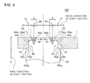
- FIG. 4 is a schematic cross-sectional view for describing a joint structure 200 of the nozzle vane 2 and the lever 1 described above, according to some embodiments.
- the through hole 42 of the lever 1 includes a fitting surface 42a to be fitted with a peripheral surface 72 of one end side of the shaft portion 2a of the nozzle vane 2.
- the one end side of the shaft portion 2a and the lever 1 are joined to each other by welding.
- Weld metal 50 at a welded part 40 between the one end side of the shaft portion 2a and the lever 1 is formed such that a center position 64 of the weld metal 50 is inside a position 17 of the fitting surface 42a in the radial direction of the shaft portion 2a.
- the center position 64 of the weld metal 50 in the radial direction of the shaft portion 2a refers to a center position of a range S formed by the weld metal 50 in the radial direction of the shaft portion 2a, the center position being a midpoint between the first end 50a and the second end 50b of the weld metal 50 in the radial direction of the shaft portion 2a.
- FIG. 5 is a schematic cross-sectional view for describing a joint structure 300 of the nozzle vane 2 and the lever 1 described above, according to a comparative example.
- the weld metal 50 is formed such that the center position 64 of the weld metal 50 coincides with the position 17 of the fitting surface 42a of the lever 1 in the radial direction of the shaft portion 2a (in a common welding method, these positions coincide).
- the weld metal 50 is cooled by a base member to solidify from periphery to center.
- deformation due to solidification of the weld metal 50 causes the peripheral surface 72 of the shaft portion 2a and the fitting surface 42a of the lever 1 to move away from each other, as illustrated in FIG. 6A .
- a crack may be produced in a non-solidified region of the weld metal 50 (a center region M of the weld metal 50 being the final solidification region), as illustrated in FIG. 6B .
- the crack may expand during usage of the nozzle vane 2 and the lever 1, and the welded part 40 between the nozzle vane 2 and the lever 1 may break apart.
- the weld metal 50 is formed such that the center position 64 of the weld metal 50 is inside the position 17 of the fitting surface 42a in the radial direction of the shaft portion 2a, as described above.
- stress applied to the non-solidified region of the weld metal 50 (the center region M of the weld metal 50 being the final solidification region) is effectively reduced, which reduces generation of a crack in the weld metal 50.
- the weld metal 50 is formed inside the fitting surface 42a in the radial direction of the shaft portion 2a.
- the range S of formation of the weld metal 50 in the radial direction of the shaft portion 2a is positioned inside, with respect to the radial direction of the shaft portion 2a, the position 17 of the fitting surface 42a in the radial direction of the shaft 2a.
- the lever 1 includes the first contact surface 42b and the second contact surface 42c.
- the first contact surface 42b is formed so as to extend inward in the radial direction of the shaft portion 2a from the first end 42a 1 of the fitting surface 42a with respect to the axial direction of the shaft portion 2a, and contact the shaft portion 2a from the axial direction of the shaft portion 2a.
- the second contact surface 42c is formed to extend outward in the radial direction of the shaft portion 2a from the second end 42a 2 of the fitting surface 42a with respect to the axial direction of the shaft portion 2a, and contact the shaft portion 2a from the axial direction of the shaft portion 2a.
- the nozzle vane 2 is composed of nickel-based alloy and the lever 1 is composed of stainless steel.
- variable geometry turbocharger is widely used for diesel engines, and the nozzle vane 2 is normally made of stainless steel (typically, austenite stainless steel).
- stainless steel typically, austenite stainless steel
- nickel-based alloy as a constituent material of the nozzle vane 2 in the variable geometry turbocharger 500 for a gasoline engine. While usable nickel-based alloy includes, for instance, Inconel, Hastelloy, Nimonic, and Waspaloy (all of which are registered trademarks), Inconel is especially suitable in terms of a strength against heat and an erosion-resistant property, and Inconel 713C is the most suitable.
- nickel-based alloy since nickel-based alloy has a high strength against heat and a high oxidization-resistant property, it is difficult to perform cold pressing such as fine blanking pressing, which could be used to join two stainless objects, to join the nozzle vane 2 and the lever 1. Thus, it is desirable to join the nozzle vane 2 to the lever 1 by welding.
- nickel-based alloy contains many types of elements such as titanium and niobium, which increases the risk of generation of the above described hot crack during welding (titanium and niobium may be a cause that increases sensitivity to hot cracking). Further, a hot crack is likely to be generated also because of a solidification crack due to concentration of impurity elements such as phosphorus and sulfur in the final solidification region.
- the nozzle vane 2 is made of nickel-based alloy to resist high-temperature exhaust gas of a gasoline engine, and the center position 64 of the weld metal 50 is disposed inside the position 17 of the fitting surface 42a in the radial direction of the shaft portion 2a to suppress generation of a hot crack in welding, which makes it possible to suitably apply the joint structure 200 to the variable geometry turbocharger 500 for a gasoline engine.
- welding may be performed either by adding weld metal, or by melting base members directly by heat radiation.
- FIG. 7 is a schematic cross-sectional view for describing a joining method and a joint structure 400 of the nozzle vane 2 and the lever 1 according to another embodiment.
- FIG. 7A is a schematic cross-sectional view for describing a method of joining the nozzle vane 2 and the lever 1 according to another embodiment
- FIG. 7B is a schematic cross-sectional view for describing a state (joint structure 400) after joining (welding) the nozzle vane 2 and the lever 1 by the joining method illustrated in FIG. 7A .
- the lever 1 is made of stainless steel and the nozzle vane 2 is made of nickel-based alloy.
- the lever 1 includes the fitting surface 42a to be fitted with the peripheral surface 72 of one end side of the shaft portion 2a.
- heat 90 is radiated to base members without adding weld metal. At this time, heat is radiated so that a radiation-center position 80 is at a position 80 outside the position 17 of the fitting surface 42a in the radial direction of the shaft portion 2a.
- various heat sources can be used, such as an electron beam and a laser.
- nickel-based alloy used in the nozzle vane 2 excels in strength against heat and oxidization resistance, but contains many types of elements such as titanium and niobium, which increases the risk of generation of a hot crack in the weld metal 50 during welding (titanium and niobium may be a cause that increases sensitivity to hot cracking).
- the lever 1 and the one end side of the shaft portion 2a are welded by radiating heat so that the radiation-center position 80 is at the position 80 outside the position 17 of the fitting surface 42a in the radial direction of the shaft portion 2a.
- the proportion of nickel-based alloy in the weld metal is reduced, and thus the proportion of e.g. titanium and niobium in the weld metal is reduced.
- generation of a crack in the weld metal 50 is reduced, which makes it possible to reduce breakage of the welded part 40 between the nozzle vane 2 and the lever 1 during usage of the nozzle vane 2 and the lever 1.
Landscapes
- Engineering & Computer Science (AREA)
- Mechanical Engineering (AREA)
- Chemical & Material Sciences (AREA)
- General Engineering & Computer Science (AREA)
- Combustion & Propulsion (AREA)
- Physics & Mathematics (AREA)
- Optics & Photonics (AREA)
- Plasma & Fusion (AREA)
- Materials Engineering (AREA)
- Chemical Kinetics & Catalysis (AREA)
- General Chemical & Material Sciences (AREA)
- Supercharger (AREA)
Description
- The present disclosure relates to a structure and a method for joining a nozzle vane and a lever, and a variable geometry turbocharger.
- A known variable geometry turbocharger to be applied to an internal combustion engine includes a nozzle vane disposed in an exhaust channel for guiding exhaust gas to a turbine wheel, the nozzle vane including a shaft portion, and a lever (arm) to be fitted to one end of the shaft portion to transmit torque to the shaft portion to adjust a vane angle of the nozzle vane (
Patent Document 1, for instance). - Patent Document 1:
JP2007-187015A - If the shaft portion of the nozzle vane and the lever used in the above described variable geometry turbocharger are to be joined by welding, a crack due to deformation accompanying solidification of weld metal (hereinafter, referred to as "a hot crack") may be generated in the weld metal in welding, and the hot crack may expand during usage of the nozzle vane and the lever to bring about breakage of a welded part.
- An object of some embodiments of the present invention is to provide a structure and a method of joining a nozzle vane and a lever, and a variable geometry turbocharger, capable of reducing breakage of a welded part between a shaft portion of the nozzle vane and the lever during usage of the nozzle vane and the lever by reducing generation of a hot crack in weld metal at the welded part.
-
- (1) A joint structure of a nozzle vane and a lever according to some embodiments of the present invention comprises: a nozzle vane to be disposed in an exhaust passage for guiding exhaust gas to a turbine wheel of a variable geometry turbocharger, the nozzle vane including a shaft portion; and a lever including a fitting surface to be fitted with a peripheral surface on one end side of the shaft portion, for transmitting torque to the shaft portion to adjust a vane angle of the nozzle vane. The lever and the one end side of the shaft portion are joined to each other by welding. Weld metal at a welded part between the lever and the one end side of the shaft portion is formed so that a center position of the weld metal is disposed inside a position of the fitting surface with respect to a radial direction of the shaft portion.
In a joint structure of a nozzle vane and a lever, if one end side of a shaft portion and the lever are to be joined by welding, weld metal is cooled by a base member to solidify from periphery to center. In response to great stress applied to the weld metal due to deformation accompanying solidification, a crack (so-called hot crack) may be produced in a non-solidified region of the weld metal, which is a center region of the weld metal being a final solidification region. If such a hot crack is produced in the weld metal, the crack may expand during usage of the nozzle vane and the lever, and the welded part between the nozzle vane and the lever may break apart.
As a result of intensive researches conducted by the present inventors on this issue, it was found that, if a position of a fitting surface of a lever to be fitted with a peripheral surface of a shaft portion coincides with the center position of weld metal in the radial direction of the shaft portion (the positions generally coincide in a normal welding method), great stress may be applied to the above region when the peripheral surface of the shaft portion and the fitting surface try to move away from each other due to deformation accompanying solidification of weld metal, thereby producing a hot crack.
Thus, the joint structure described in the above (1) employs a configuration in which, in the radial direction of the shaft portion, the center position of the weld metal is disposed inside the position of the fitting surface. In this way, even if the peripheral surface of the shaft portion and the fitting surface of the lever try to move away from each other due to deformation accompanying solidification of the weld metal, stress generated in the above region is effectively reduced, which reduces generation of a crack in the weld metal. As a result, it is possible to reduce breakage of the welded part between the nozzle vane and the lever during usage of the nozzle vane and the lever. - (2) In some embodiments, in the joint structure of a nozzle vane and a lever described in the above (1), the weld metal is formed inside the fitting surface with respect to the radial direction of the shaft portion.
With the above joint structure (3), even if the peripheral surface of the shaft portion and the fitting surface of the lever try to move away from each other due to deformation accompanying solidification of the weld metal, stress applied to the weld metal is effectively reduced, which reduces generation of a crack in the weld metal. As a result, it is possible to reduce breakage of the welded part between the nozzle vane and the lever during usage of the nozzle vane and the lever. - (3) In some embodiments, in the joint structure of a nozzle vane and a lever described in the above (1) or (2), the lever includes: a first contact surface formed to extend inward in the radial direction of the shaft portion from a first end of the fitting surface with respect to the axial direction of the shaft portion, and to contact the shaft portion from the axial direction of the shaft portion; and a second contact surface formed to extend outward in the radial direction of the shaft portion from a second end of the fitting surface with respect to the axial direction of the shaft portion, and to contact the shaft portion from the axial direction of the shaft portion.
In the above joint structure (2), with the first contact surface and the second contact surface, it is possible to suppress the motion of the peripheral surface of the shaft portion and the fitting surface of the lever to move away from each other due to deformation accompanying solidification of the weld metal. As a result, stress applied to the weld metal is effectively reduced and generation of a crack in the weld metal is reduced, which makes it possible to reduce breakage of the welded part between the nozzle vane and the lever during usage of the nozzle vane and the lever. - (4) In some embodiments, in the joint structure of a nozzle vane and a lever described in any one of the above (1) to (3), the variable geometry turbocharger is for a gasoline engine, and the nozzle vane is composed of nickel-based alloy, and the lever is composed of stainless steel.
Conventionally, a variable geometry turbocharger is widely used for diesel engines, and a nozzle component is normally made of stainless steel (typically, austenite stainless steel). In contrast, if a variable geometry turbocharger is to be used in a gasoline engine, it is difficult to use stainless steel as a material of the nozzle vane for the following reason. That is, the nozzle vane is exposed to high-temperature exhaust gas due to its function, and an exhaust-gas temperature of a gasoline engine is higher than that of a diesel engine (in an example, an exhaust-gas temperature of a diesel engine is approximately 850 degrees and that of a gasoline engine is approximately 1000 degrees). Thus, it is difficult to use stainless steel in view of thermal stress, thermal expansion, and oxidization generated at the exhaust-gas temperature of a gasoline engine. In this context, it is desirable to use nickel-based alloy as a constituent material of a nozzle vane in a variable geometry turbocharger for a gasoline engine.
On the other hand, since nickel-based alloy has a high strength against heat and a high oxidization-resistant property, it is difficult to perform cold pressing such as fine blanking pressing, which could be used to join two stainless objects, to join the nozzle vane and the lever. Thus, it is desirable to join the nozzle vane to the lever by welding.
However, nickel-based alloy contains many types of elements such as titanium and niobium, which increases the risk of generation of the above described hot crack during welding (titanium and niobium may be a cause that increases sensitivity to hot cracking).
In this regard, in the above joint structure (4), the nozzle vane is made of nickel-based alloy to resist high-temperature exhaust gas of a gasoline engine, and the joint structure described in the above (1) is employed to reduce generation of a hot crack in welding, which makes it possible to suitably apply the joint structure to a variable geometry turbocharger for a gasoline engine. - (5) A variable geometry turbocharger according to some embodiments comprises: the joint structure according to any one of the above (1) to (4); the turbine wheel; and a compressor driven by the turbine wheel.
With the above variable geometry turbocharger (5), at least the above joint structure (1) is provided. Thus, even if the peripheral surface of the shaft portion and the fitting surface of the lever try to move away from each other due to deformation accompanying solidification of the weld metal, stress generated in the above region is effectively reduced, which reduces generation of a crack in the weld metal. In this way, it is possible to achieve stable operation of the turbocharger. - (6) A joint structure of a nozzle vane and a lever according to some embodiments comprises: a nozzle vane to be disposed in an exhaust passage for guiding exhaust gas to a turbine wheel of a variable geometry turbocharger, the nozzle vane including a shaft portion; and a lever including a fitting surface to be fitted with a peripheral surface on one end side of the shaft portion, for transmitting torque to the shaft portion to adjust a vane angle of the nozzle vane. The nozzle vane is composed of nickel-based alloy, the lever is composed of stainless steel, and the lever and the one end side of the shaft portion are welded to each other, and a radiation-center position radiated by heat for welding is disposed outside a position of the fitting surface with respect to a radial direction of the shaft portion.
Since a nozzle vane made of nickel-based alloy has a high strength against heat and a high oxidization-resistant property, it is difficult to perform cold pressing such as fine blanking pressing, which could be used to join two stainless objects, to join the nozzle vane and the lever. Thus, it is desirable to join the nozzle vane to the lever by welding.
However, nickel-based alloy contains many types of elements such as titanium and niobium, which increases the risk of generation of a hot crack in weld metal during welding (titanium and niobium may be a cause that increases sensitivity to hot cracking).
In this regard, with the above joint structure (6), the lever and the one end side of the shaft portion are welded by radiating heat so that the radiation-center position is at the position outside the position of the fitting surface with respect to the radial direction of the shaft portion. In this way, in welding, the proportion of nickel-based alloy in the weld metal is reduced, and thus the proportion of e.g. titanium and niobium in the weld metal is reduced. As a result, generation of a hot crack in the weld metal at the time of welding is reduced, which makes it possible to reduce breakage of the welded part between the nozzle vane and the lever during usage of the nozzle vane and the lever. - (7) In some embodiments, in the joint structure of a nozzle vane and a lever described in the above (6), an expression of D/S ≥ 0.25 is satisfied, where D is a distance between the radiation-center position and the position of the fitting surface with respect to the radial direction of the shaft portion and S is a width of weld metal with respect to the radial direction of the shaft portion.
With the above joint structure (7) of a nozzle vane and a lever, the proportion of nickel-based alloy in the weld metal is sufficiently reduced, and thus the proportion of e.g. titanium and niobium in the weld metal is sufficiently reduced. As a result, generation of a hot crack in the weld metal at the time of welding is reduced effectively, which makes it possible to reduce breakage of the welded part between the nozzle vane and the lever during usage of the nozzle vane and the lever. - (8) A variable geometry turbocharger according to some embodiments comprises: the joint structure of a nozzle vane and a lever according to the above (6) or (7); the turbine wheel; and a compressor driven by the turbine wheel.
With the above variable geometry turbocharger (8), since at least the above joint structure (6) is provided, at the time of welding the lever and one end side of the shaft portion of the nozzle vane, the proportion of nickel-based alloy in the weld metal is reduced, and thus the proportion of e.g. titanium and niobium in the weld metal is reduced. Accordingly, generation of a hot crack in weld metal at the time of welding is reduced. As a result, it is possible to reduce breakage of the welded part between the nozzle vane and the lever in operation of the turbocharger. - (9) A method of joining a nozzle vane and a lever by welding according to some embodiments comprises: providing a nozzle vane to be disposed in an exhaust passage for guiding exhaust gas to a turbine wheel of a variable geometry turbocharger, the nozzle vane including a shaft portion and being composed of nickel-based alloy, and a lever including a fitting surface to be fitted with a peripheral surface on one end side of the shaft portion, for transmitting torque to the shaft portion to adjust a vane angle of the nozzle vane, the lever being composed of stainless steel; and welding the lever and the one end side of the shaft portion by radiating heat to the lever and the one end side of the shaft portion so that a radiation-center position is disposed outside a position of the fitting surface with respect to a radial direction of the shaft portion.
Since a nozzle vane made of nickel-based alloy has a high strength against heat and a high oxidization-resistant property, it is difficult to perform cold pressing such as fine blanking pressing, which could be used to join two stainless objects, to join the nozzle vane and the lever. Thus, it is desirable to join the nozzle vane to the lever by welding.
However, nickel-based alloy contains many types of elements such as titanium and niobium, which increases the risk of generation of a hot crack in weld metal during welding (titanium and niobium may be a cause that increases sensitivity to hot cracking).
In this regard, with the above joining method (9), the lever and the one end side of the shaft portion are welded by radiating heat so that the radiation-center position is at the position outside the position of the fitting surface in the radial direction of the shaft portion. In this way, in welding, the proportion of nickel-based alloy in the weld metal is reduced, and thus the proportion of e.g. titanium and niobium in the weld metal is reduced. As a result, generation of a hot crack in the weld metal at the time of welding is reduced, which makes it possible to reduce breakage of the welded part between the nozzle vane and the lever during usage of the nozzle vane and the lever. - (10) In some embodiments, in the method of joining a nozzle vane and a lever according to the above (9), heat is radiated so that an expression of D/S ≥ 0.25 is satisfied, where D is a distance between the radiation-center position and the position of the fitting surface with respect to the radial direction of the shaft portion and S is a width of weld metal with respect to the radial direction of the shaft portion.
- According to the above method (10) of joining a nozzle vane and a lever, the proportion of nickel-based alloy in the weld metal is sufficiently reduced, and thus the proportion of e.g. titanium and niobium in the weld metal is sufficiently reduced. As a result, generation of a crack in the weld metal at the time of welding is reduced effectively, which makes it possible to reduce breakage of the welded part between the nozzle vane and the lever during usage of the nozzle vane and the lever.
- According to some embodiments of the present invention, it is possible to provide a structure and a method of joining a nozzle vane and a lever, and a variable geometry turbocharger, capable of reducing breakage of a welded part between a shaft portion of the nozzle vane and the lever during usage of the nozzle vane and the lever by reducing generation of a hot crack in weld metal at the welded part.
-
-
FIG. 1 is a vertical cross-sectional view of a variable-displacement type turbocharger for a gasoline engine according to some embodiments. -
FIG. 2A is a front view of a variable nozzle mechanism as seen from a lever side, according to some embodiments.FIG. 2B is a cross-sectional view taken along line A-A inFIG. 2A . -
FIG. 3 is a schematic perspective view for describing a configuration of a nozzle vane and a lever according to some embodiments. -
FIG. 4 is a schematic cross-sectional view for describing a joint structure of a nozzle vane and a lever according to some embodiments. -
FIG. 5 is a schematic cross-sectional view for describing a joint structure of a nozzle vane and a lever according to a comparative example. -
FIG. 6A is a schematic cross-sectional view for describing a manner of deformation accompanying solidification of weld metal in a joint structure of a nozzle vane and a lever according to a comparative example.FIG. 6B is a schematic cross-sectional view for describing a state in which a hot crack is formed in weld metal in a joint structure of a nozzle vane and a lever according to a comparative example. -
FIG. 7A is a schematic cross-sectional view for describing a method of joining a nozzle vane and a lever according to another embodiment, andFIG. 7B is a schematic cross-sectional view for describing a state after joining (welding) a nozzle vane and a lever by the method illustrated inFIG. 7A . - Embodiments of the present invention will now be described in detail with reference to the accompanying drawings.
- It is intended, however, that unless particularly specified, dimensions, materials, shapes, relative positions and the like of components described in the embodiments shall be interpreted as illustrative only and not intended to limit the scope of the present invention.
-
FIG. 1 is a vertical cross-sectional view of avariable geometry turbocharger 500 for a gasoline engine according to some embodiments. - In
FIG. 1 ,30 is a turbine casing and 38 is a scroll part formed in a spiral shape on an outer peripheral part of theturbine casing 30. 34 is a turbine wheel of a radial-flow type, 35 is a compressor, 32 is a turbine shaft coupling theturbine wheel 34 and thecompressor - The
turbine shaft 32 coupling theturbine wheel 34 and thecompressor 35 is supported rotatably to the bearinghousing 36 via twobearings variable geometry turbocharger 500. - 2 is a nozzle vane, and a plurality of
nozzle vanes 2 is disposed at regular intervals in a circumferential direction on a radially inner side of thescroll 38. Ashaft portion 2a is formed on a blade end portion of eachnozzle vane 2 and supported revolvably to anozzle mount 5 fixed to theturbine casing 30. Thenozzle vanes 2 are disposed in an exhaust channel for guiding exhaust gas to theturbine wheel 34. - A lever (lever plate) 1 is coupled to an opposite side of the
shaft portion 2a from the blade end portion. Thelever 1 transmits torque received from adrive ring 3 to theshaft portion 2a to revolve theshaft portion 2a, thereby changing a vane angle of thenozzle vane 2. - 33 is an actuator rod which transmits reciprocating motion from an actuator (not illustrated). Reciprocating motion of the
actuator rod 33 is converted into rotational motion via alink 15 fixed to arotational shaft 15a. Anarm 15b is fixed to therotation shaft 15a, and adrive pin 15c is disposed on the other end portion of thearm 15b. Thedrive pin 15c engages with anengagement groove 3z (seeFIG. 2 ) formed on an outer peripheral part of thedrive ring 3, and thelink 15 transmits rotational motion converted from the reciprocating motion to thedrive ring 3 to drive thedrive ring 3. A single-dotted chain circle in the drawing indicates avariable nozzle mechanism 100 for changing vane angles of thenozzle vanes 2. - During operation of the
variable geometry turbocharger 500 with the configuration illustrated inFIG. 1 , exhaust gas from an internal combustion engine (not illustrated) enters thescroll part 38, flows around along the spiral shape of thescroll part 38, and then flows into thenozzle vanes 2 while going around. Then, the exhaust gas flows through vane gaps (openings) between thenozzle vanes 2 to flow into theturbine wheel 34 inward, flows in the radial direction toward the center to perform expansion work on theturbine wheel 34, and then is guided along the axial direction to an exhaust-gas outlet 8 to be discharged outside. - To control a displacement of the above variable geometry turbine, a vane angle of the
nozzle vanes 2 is set for the above actuator by a vane-angle control unit (not illustrated), the vane angle being such that a flow rate of exhaust gas flowing through thenozzle vanes 2 becomes a required flow rate. A reciprocation displacement of the actuator corresponding to such a vane angle is transmitted to thedrive ring 3 via thelink 15 to drive thedrive ring 3 to rotate. - In response to revolution of the
drive ring 3, thelever 1 coupled to thedrive ring 3 via a coupling-pin portion 10 revolves theshaft portions 2a of thenozzle vanes 2. Revolution of theshaft portion 2a causes thenozzle vanes 2 to revolve to achieve the vane angle set by the actuator, and thereby the size of the vane gaps (opening) changes. -
FIGs. 2A and 2B illustrate avariable nozzle mechanism 100.FIG. 2A is a front view as seen from alever 1 side.FIG. 2B is a cross-sectional view taken along line A-A inFIG. 2A . - The
variable nozzle mechanism 100 is configured as follows to change the vane angle of thenozzle vanes 2. - 3 is a drive ring formed in a disc shape, fitted onto a
guide portion 5a of a circular shape (annular shape) projecting in the direction of the axis CL of the nozzle mount 5 (which is the same as the rotational axis of the variable geometry turbocharger 500) to be supported revolvably. On the outer peripheral side of thedrive ring 3,groove portions 3y to be engaged with thecoupling pin portions 10 of thelevers 1 are formed at regular intervals in the circumferential direction. 3z is a drive groove to be engaged with anactuator rod 33. - The same number of
levers 1 as the number of thegroove portions 3y of thedrive ring 3 are provided at regular intervals in the circumferential direction. The outer peripheral side (one end side) of eachlever 1 is fitted into corresponding one of thegroove portions 3y disposed on thedrive ring 3 via corresponding one of thecoupling pin portions 10, and the inner peripheral side (the other end side) of eachlever 1 is joined to corresponding one of theshaft portions 2a of thenozzle vanes 2. - The
shaft portions 2a are each supported via an axis revolvably to thenozzle mount 5. 6 is a nozzle plate formed in an annular shape, and 61 is a plurality of nozzle supports coupling thenozzle plate 6 and thenozzle mount 5. - 7 is a stopper pin. A plurality of
stopper pins 7 is disposed at regular intervals in the circumferential direction on an outer peripheral edge portion of an end surface of theguide portion 5a of a cylindrical shape (annular shape) projecting in the direction of the axis CL at the center part of thenozzle mount 5, and fitted into fit-in holes (not illustrated) disposed to extend along the direction of the axis CL (at four positions in the present embodiment). - The stopper pins 7 are so-called opening-degree restricting members which restrict pivoting of the
levers 1 at closed positions at the vane gaps (opening) of thenozzle vanes 2, each of thelevers 1 pivoting about theshaft portion 2a of thenozzle vane 2 accompanying revolution of thedrive ring 3. - 9 is a lock pin. The
lock pin 9 is a position-determining pin for improving mounting accuracy of the bearinghousing 36 and thenozzle mount 5. Thelock pin 9 restricts an assembly angle of the bearinghousing 36 and the nozzle mount 5 (assembly accuracy), so that a drive amount of thedrive ring 3 transmits accurately in accordance with a drive amount of the actuator, and the opening degree of thenozzle vanes 2 is accurately controlled, thereby causing the turbocharger to operate with a sufficient performance. - In the
variable nozzle mechanism 100, thedrive ring 3 is disposed between a side surface of thelever 1 and a side surface of thenozzle mount 5, as illustrated inFIG. 2B . Thelever 1, thedrive ring 3, and thenozzle mount 5 are disposed in parallel in the axial direction. In some embodiments, thecoupling pin portion 10 is formed integrally with thelever 1. -
FIG. 3 is a schematic perspective view for describing a configuration of the above describednozzle vane 2 and thelever 1. - As illustrated in
FIG. 3 , a throughhole 42 is formed on an end side of thelever 1, and the throughhole 42 fits onto an end side of theshaft portion 2a of thenozzle vane 2. Further, the above describedcoupling pin portion 10 is formed on the other end side of thelever 1. -
FIG. 4 is a schematic cross-sectional view for describing ajoint structure 200 of thenozzle vane 2 and thelever 1 described above, according to some embodiments. - In the
joint structure 200 illustrated inFIG. 4 , the throughhole 42 of thelever 1 includes afitting surface 42a to be fitted with aperipheral surface 72 of one end side of theshaft portion 2a of thenozzle vane 2. The one end side of theshaft portion 2a and thelever 1 are joined to each other by welding.Weld metal 50 at a weldedpart 40 between the one end side of theshaft portion 2a and thelever 1 is formed such that acenter position 64 of theweld metal 50 is inside aposition 17 of thefitting surface 42a in the radial direction of theshaft portion 2a. Thecenter position 64 of theweld metal 50 in the radial direction of theshaft portion 2a refers to a center position of a range S formed by theweld metal 50 in the radial direction of theshaft portion 2a, the center position being a midpoint between thefirst end 50a and thesecond end 50b of theweld metal 50 in the radial direction of theshaft portion 2a. -
FIG. 5 is a schematic cross-sectional view for describing ajoint structure 300 of thenozzle vane 2 and thelever 1 described above, according to a comparative example. In thejoint structure 300 illustrated inFIG. 5 , theweld metal 50 is formed such that thecenter position 64 of theweld metal 50 coincides with theposition 17 of thefitting surface 42a of thelever 1 in the radial direction of theshaft portion 2a (in a common welding method, these positions coincide). - In the
joint structure 300, when thenozzle vane 2 and thelever 1 are welded, theweld metal 50 is cooled by a base member to solidify from periphery to center. At this time, deformation due to solidification of theweld metal 50 causes theperipheral surface 72 of theshaft portion 2a and thefitting surface 42a of thelever 1 to move away from each other, as illustrated inFIG. 6A . If large stress is applied to theweld metal 50 due to deformation accompanying solidification in welding, a crack (so-called hot crack) may be produced in a non-solidified region of the weld metal 50 (a center region M of theweld metal 50 being the final solidification region), as illustrated inFIG. 6B . - If such a hot crack is produced in the
weld metal 50, the crack may expand during usage of thenozzle vane 2 and thelever 1, and the weldedpart 40 between thenozzle vane 2 and thelever 1 may break apart. - In contrast, in the
joint structure 200 of thenozzle vane 2 and thelever 1 according to some embodiments illustrated inFIG. 4 , theweld metal 50 is formed such that thecenter position 64 of theweld metal 50 is inside theposition 17 of thefitting surface 42a in the radial direction of theshaft portion 2a, as described above. In this way, even if theperipheral surface 72 of theshaft portion 2a and thefitting surface 42a of thelever 1 try to move away from each other due to deformation accompanying solidification of theweld metal 50 during welding, stress applied to the non-solidified region of the weld metal 50 (the center region M of theweld metal 50 being the final solidification region) is effectively reduced, which reduces generation of a crack in theweld metal 50. As a result, it is possible to reduce breakage of the weldedpart 40 between thenozzle vane 2 and thelever 1 during usage of thenozzle vane 2 and thelever 1. Further, it is possible to achieve stable operation of thevariable geometry turbocharger 500. - In the
joint structure 200 of thenozzle vane 2 and thelever 1 illustrated inFIG. 4 , theweld metal 50 is formed inside thefitting surface 42a in the radial direction of theshaft portion 2a. Specifically, the range S of formation of theweld metal 50 in the radial direction of theshaft portion 2a is positioned inside, with respect to the radial direction of theshaft portion 2a, theposition 17 of thefitting surface 42a in the radial direction of theshaft 2a. In this way, if a peripheral surface of theshaft portion 2a and thefitting surface 42a of thelever 1 try to move away from each other due to deformation accompanying solidification of theweld metal 50, stress applied to theweld metal 50 is effectively reduced, which reduces generation of a crack in theweld metal 50. As a result, it is possible to reduce breakage of the weldedpart 40 between thenozzle vane 2 and thelever 1 during usage of thenozzle vane 2 and thelever 1. - In the
joint structure 200 of thenozzle vane 2 and thelever 1 illustrated inFIG. 4 , thelever 1 includes thefirst contact surface 42b and thesecond contact surface 42c. Thefirst contact surface 42b is formed so as to extend inward in the radial direction of theshaft portion 2a from thefirst end 42a1 of thefitting surface 42a with respect to the axial direction of theshaft portion 2a, and contact theshaft portion 2a from the axial direction of theshaft portion 2a. Thesecond contact surface 42c is formed to extend outward in the radial direction of theshaft portion 2a from thesecond end 42a2 of thefitting surface 42a with respect to the axial direction of theshaft portion 2a, and contact theshaft portion 2a from the axial direction of theshaft portion 2a. In this way, with thefirst contact surface 42b and thesecond contact surface 42c, it is possible to suppress the motion of theperipheral surface 72 of one end side of theshaft portion 2a and thefitting surface 42a of thelever 1 to move away from each other due to deformation accompanying solidification of theweld metal 50. As a result, stress applied to theweld metal 50 is effectively reduced and generation of a crack in theweld metal 50 is reduced, which makes it possible to reduce breakage of the weldedpart 40 between thenozzle vane 2 and thelever 1 during usage of thenozzle vane 2 and thelever 1. - In the
joint structure 200 between thenozzle vane 2 and thelever 1 illustrated inFIG. 4 , thenozzle vane 2 is composed of nickel-based alloy and thelever 1 is composed of stainless steel. - Conventionally, a variable geometry turbocharger is widely used for diesel engines, and the
nozzle vane 2 is normally made of stainless steel (typically, austenite stainless steel). In contrast, if a variable geometry turbocharger is to be used in a gasoline engine, it is difficult to use stainless steel as a material of thenozzle vane 2 for the following reason. That is, thenozzle vane 2 is exposed to high-temperature exhaust gas due to its function, and an exhaust-gas temperature of a gasoline engine is higher than that of a diesel engine (in an example, an exhaust-gas temperature of a diesel engine is approximately 850 degrees and that of a gasoline engine is approximately 1000 degrees). Thus, it is difficult to use stainless steel in view of thermal stress, thermal expansion, and high-temperature oxidization generated at the exhaust-gas temperature of a gasoline engine. In this context, it is desirable to use nickel-based alloy as a constituent material of thenozzle vane 2 in thevariable geometry turbocharger 500 for a gasoline engine. While usable nickel-based alloy includes, for instance, Inconel, Hastelloy, Nimonic, and Waspaloy (all of which are registered trademarks), Inconel is especially suitable in terms of a strength against heat and an erosion-resistant property, and Inconel 713C is the most suitable. - On the other hand, since nickel-based alloy has a high strength against heat and a high oxidization-resistant property, it is difficult to perform cold pressing such as fine blanking pressing, which could be used to join two stainless objects, to join the
nozzle vane 2 and thelever 1. Thus, it is desirable to join thenozzle vane 2 to thelever 1 by welding. However, nickel-based alloy contains many types of elements such as titanium and niobium, which increases the risk of generation of the above described hot crack during welding (titanium and niobium may be a cause that increases sensitivity to hot cracking). Further, a hot crack is likely to be generated also because of a solidification crack due to concentration of impurity elements such as phosphorus and sulfur in the final solidification region. - In this regard, with the
joint structure 200 illustrated inFIG. 4 , thenozzle vane 2 is made of nickel-based alloy to resist high-temperature exhaust gas of a gasoline engine, and thecenter position 64 of theweld metal 50 is disposed inside theposition 17 of thefitting surface 42a in the radial direction of theshaft portion 2a to suppress generation of a hot crack in welding, which makes it possible to suitably apply thejoint structure 200 to thevariable geometry turbocharger 500 for a gasoline engine. - Further, to join the
nozzle vane 2 and thelever 1 to form thejoint structure 200 described inFIG. 4 , welding may be performed either by adding weld metal, or by melting base members directly by heat radiation. -
FIG. 7 is a schematic cross-sectional view for describing a joining method and ajoint structure 400 of thenozzle vane 2 and thelever 1 according to another embodiment.FIG. 7A is a schematic cross-sectional view for describing a method of joining thenozzle vane 2 and thelever 1 according to another embodiment, andFIG. 7B is a schematic cross-sectional view for describing a state (joint structure 400) after joining (welding) thenozzle vane 2 and thelever 1 by the joining method illustrated inFIG. 7A . - In
FIG. 7A , thelever 1 is made of stainless steel and thenozzle vane 2 is made of nickel-based alloy. Thelever 1 includes thefitting surface 42a to be fitted with theperipheral surface 72 of one end side of theshaft portion 2a. - In the method of joining the
nozzle vane 2 and thelever 1 illustrated inFIG. 7A , to join thenozzle vane 2 and thelever 1 by welding,heat 90 is radiated to base members without adding weld metal. At this time, heat is radiated so that a radiation-center position 80 is at aposition 80 outside theposition 17 of thefitting surface 42a in the radial direction of theshaft portion 2a. As a heat source herein, various heat sources can be used, such as an electron beam and a laser. - As described above, nickel-based alloy used in the
nozzle vane 2 excels in strength against heat and oxidization resistance, but contains many types of elements such as titanium and niobium, which increases the risk of generation of a hot crack in theweld metal 50 during welding (titanium and niobium may be a cause that increases sensitivity to hot cracking). - In this regard, according to the above joining method illustrated in
FIG. 7A , thelever 1 and the one end side of theshaft portion 2a are welded by radiating heat so that the radiation-center position 80 is at theposition 80 outside theposition 17 of thefitting surface 42a in the radial direction of theshaft portion 2a. In this way, in welding, the proportion of nickel-based alloy in the weld metal is reduced, and thus the proportion of e.g. titanium and niobium in the weld metal is reduced. As a result, generation of a crack in theweld metal 50 is reduced, which makes it possible to reduce breakage of the weldedpart 40 between thenozzle vane 2 and thelever 1 during usage of thenozzle vane 2 and thelever 1. Further, it is possible to achieve stable operation of thevariable geometry turbocharger 500. - Further, in the joining method illustrated in
FIG. 7A , it is desirable to radiate heat so as to satisfy an expression of D/S ≥ 0.25, where D is a distance between the radiation-center position 80 and the position 17 (groove-center position) of thefitting surface 42a of thelever 1 in the radial direction of theshaft portion 2a, and S is a width of theweld metal 50 in the radial direction of theshaft portion 2a (seeFIG. 7B ). In this way, the proportion of nickel-based alloy in the weld metal is sufficiently reduced, and thus the proportion of e.g. titanium and niobium in the weld metal is sufficiently reduced. As a result, generation of a hot crack in theweld metal 50 is effectively reduced, which makes it possible to reduce breakage of the weldedpart 40 between thenozzle vane 2 and thelever 1 during usage of thenozzle vane 2 and thelever 1. -
- 1
- Lever
- 2
- Nozzle vane
2a Shaft portion
3 Drive ring
3y Groove portion
3z Engagement groove
5Nozzle mount 5a Guide portion
6 Nozzle plate
7 Stopper pin
8 Exhaust-gas outlet
9 Lock pin
10 Coupling pin portion
15 Link
15a Rotational shaft
15b Arm
15c Drive pin
17 Position of fitting surface in radial direction of shaft portion
30 Turbine casing
32 Turbine shaft
33 Actuator Rod
34 Turbine wheel
35 Compressor
36 Bearing housing
37 Bearing
38 Scroll
40 Welded part
42 Throughhole 42a Fitting surface
42a1 First end of fitting surface in axial direction of shaft portion
42a2 Second end of fitting surface in axial direction of shaft portion
42b First contact surface
42c Second contact surface
50 Welded part
50a First end of weld metal in radial direction of shaft portion
50b Second end of weld metal in radial direction of shaft portion
64 Center position of weld metal in radial direction of shaft portion
72 Peripheral surface of one end side of shaft portion
80 Radiation center position
90 Heat source
100 Variable nozzle mechanism
200,300,400 Joint structure
500 Variable geometry turbocharger
Claims (10)
- A joint structure of a nozzle vane and a lever, comprising:a nozzle vane to be disposed in an exhaust passage for guiding exhaust gas to a turbine wheel of a variable geometry turbocharger, the nozzle vane including a shaft portion; anda lever including a fitting surface to be fitted with a peripheral surface on one end side of the shaft portion, for transmitting torque to the shaft portion to adjust a vane angle of the nozzle vane,wherein the lever and the one end side of the shaft portion are joined to each other by welding, andwherein weld metal at a welded part between the lever and the one end side of the shaft portion is formed so that a center position of the weld metal is disposed inside a position of the fitting surface with respect to a radial direction of the shaft portion.
- The joint structure of a nozzle vane and a lever, according to claim 1,
wherein the weld metal is formed inside the fitting surface with respect to the radial direction of the shaft portion. - The joint structure of a nozzle vane and a lever, according to claim 1 or 2,
wherein the lever includesa first contact surface formed to extend inward in the radial direction of the shaft portion from a first end of the fitting surface with respect to the axial direction of the shaft portion, and to contact the shaft portion from the axial direction of the shaft portion, anda second contact surface formed to extend outward in the radial direction of the shaft portion from a second end of the fitting surface with respect to the axial direction of the shaft portion, and to contact the shaft portion from the axial direction of the shaft portion. - The joint structure of a nozzle vane and a lever, according to any one of claims 1 to 3,
wherein the variable geometry turbocharger is for a gasoline engine, and
wherein the nozzle vane is composed of nickel-based alloy, and the lever is composed of stainless steel. - A variable geometry turbocharger, comprising:the joint structure of a nozzle vane and a lever according to any one of claims 1 to 4;the turbine wheel; anda compressor driven by the turbine wheel.
- A joint structure of a nozzle vane and a lever, comprising:a nozzle vane to be disposed in an exhaust passage for guiding exhaust gas to a turbine wheel of a variable geometry turbocharger, the nozzle vane including a shaft portion; anda lever including a fitting surface to be fitted with a peripheral surface on one end side of the shaft portion, for transmitting torque to the shaft portion to adjust a vane angle of the nozzle vane,wherein the nozzle vane is composed of nickel-based alloy,wherein the lever is composed of stainless steel, andwherein the lever and the one end side of the shaft portion are welded to each other, and a radiation-center position radiated by heat for welding is disposed outside a position of the fitting surface with respect to a radial direction of the shaft portion.
- The joint structure of a nozzle vane and a lever according to claim 6,
wherein an expression of D/S ≥ 0.25 is satisfied, where D is a distance between the radiation-center position and the position of the fitting surface with respect to the radial direction of the shaft portion and S is a width of weld metal with respect to the radial direction of the shaft portion. - A variable geometry turbocharger, comprising:the joint structure of a nozzle vane and a lever according to claim 6 or 7;the turbine wheel; anda compressor driven by the turbine wheel.
- A method of joining a nozzle vane and a lever by welding, comprising:providinga nozzle vane to be disposed in an exhaust passage for guiding exhaust gas to a turbine wheel of a variable geometry turbocharger, the nozzle vane including a shaft portion and being composed of nickel-based alloy, anda lever including a fitting surface to be fitted with a peripheral surface on one end side of the shaft portion, for transmitting torque to the shaft portion to adjust a vane angle of the nozzle vane, the lever being composed of stainless steel; andwelding the lever and the one end side of the shaft portion by radiating heat to the lever and the one end side of the shaft portion so that a radiation-center position is disposed outside a position of the fitting surface with respect to a radial direction of the shaft portion.
- The method of joining a nozzle vane and a lever according to claim 9,
wherein heat is radiated so that an expression of D/S ≥ 0.25 is satisfied, where D is a distance between the radiation-center position and the position of the fitting surface with respect to the radial direction of the shaft portion and S is a width of weld metal with respect to the radial direction of the shaft portion.
Applications Claiming Priority (1)
| Application Number | Priority Date | Filing Date | Title |
|---|---|---|---|
| PCT/JP2013/083552 WO2015092843A1 (en) | 2013-12-16 | 2013-12-16 | Structure and method for bonding nozzle vane and lever, and variable-capacity turbocharger |
Publications (3)
| Publication Number | Publication Date |
|---|---|
| EP3085920A1 true EP3085920A1 (en) | 2016-10-26 |
| EP3085920A4 EP3085920A4 (en) | 2017-01-04 |
| EP3085920B1 EP3085920B1 (en) | 2019-11-20 |
Family
ID=53402239
Family Applications (1)
| Application Number | Title | Priority Date | Filing Date |
|---|---|---|---|
| EP13899660.8A Not-in-force EP3085920B1 (en) | 2013-12-16 | 2013-12-16 | Structure and method for bonding nozzle vane and lever, and variable-capacity turbocharger |
Country Status (5)
| Country | Link |
|---|---|
| US (1) | US10480399B2 (en) |
| EP (1) | EP3085920B1 (en) |
| JP (1) | JP6234478B2 (en) |
| CN (1) | CN105723068B (en) |
| WO (1) | WO2015092843A1 (en) |
Cited By (3)
| Publication number | Priority date | Publication date | Assignee | Title |
|---|---|---|---|---|
| US9874106B2 (en) * | 2015-10-21 | 2018-01-23 | Borgwarner Inc. | VTG lever positive displacement press joint |
| US10641125B2 (en) | 2016-03-03 | 2020-05-05 | Ihi Corporation | Nozzle drive mechanism, turbocharger, and variable-capacity turbocharger |
| CN117961200A (en) * | 2024-04-02 | 2024-05-03 | 成都晨发泰达航空科技股份有限公司 | PSP solder segment-changing welding device for superalloy guide blade |
Families Citing this family (7)
| Publication number | Priority date | Publication date | Assignee | Title |
|---|---|---|---|---|
| US10302011B2 (en) * | 2015-11-23 | 2019-05-28 | Garrett Transportation I Inc. | Exhaust gas variable turbine assembly |
| US10393009B2 (en) * | 2016-04-19 | 2019-08-27 | Garrett Transportation I Inc. | Adjustable-trim centrifugal compressor for a turbocharger |
| CA3101061A1 (en) | 2018-06-20 | 2019-12-26 | Digital Alloys Incorporated | Multi-diameter wire feeder |
| WO2020075370A1 (en) * | 2018-10-09 | 2020-04-16 | 株式会社Ihi | Variable geometry mechanism and supercharger |
| CN109356671A (en) * | 2018-12-16 | 2019-02-19 | 中国航发沈阳发动机研究所 | A kind of adjustable stator blade angle adjusting mechanism |
| JP7155429B2 (en) * | 2019-06-26 | 2022-10-18 | 三菱重工エンジン&ターボチャージャ株式会社 | Variable nozzle device and variable capacity exhaust turbocharger |
| DE102022102421A1 (en) * | 2022-02-02 | 2023-08-03 | MTU Aero Engines AG | BLADE ASSEMBLY FOR A FLUID MACHINE |
Family Cites Families (17)
| Publication number | Priority date | Publication date | Assignee | Title |
|---|---|---|---|---|
| JPH03239935A (en) * | 1990-02-19 | 1991-10-25 | Delphi Co Ltd | Constitution of pressure sensor and its assembling method |
| FR2732630B1 (en) * | 1995-04-04 | 1997-06-20 | Lorraine Laminage | EDGE-TO-EDGE WELDING METHOD OF TWO METAL BLANKS |
| JP3735262B2 (en) * | 2001-02-27 | 2006-01-18 | 三菱重工業株式会社 | Variable nozzle mechanism for variable capacity turbine and manufacturing method thereof |
| FR2850138A1 (en) * | 2003-01-16 | 2004-07-23 | Snecma Moteurs | ANTI-WEAR DEVICE FOR A VARIABLE CALIBRATION SYSTEM OF A TURBOMACHINE BLADE |
| JP4661598B2 (en) * | 2006-01-11 | 2011-03-30 | トヨタ自動車株式会社 | Variable capacity turbocharger |
| JP4885118B2 (en) | 2007-12-21 | 2012-02-29 | 三菱重工業株式会社 | Variable displacement exhaust turbocharger with variable nozzle mechanism |
| JP5100487B2 (en) * | 2008-04-25 | 2012-12-19 | 日立粉末冶金株式会社 | Manufacturing method of sintered machine parts |
| JP2010151008A (en) * | 2008-12-25 | 2010-07-08 | Toyota Industries Corp | Variable nozzle turbocharger |
| JP2012000618A (en) * | 2010-06-14 | 2012-01-05 | Toshiba Corp | Welding method |
| JP2012061498A (en) * | 2010-09-16 | 2012-03-29 | Ihi Corp | Welding method and welded joint of steel material to ni-based superalloy |
| JP2012061499A (en) * | 2010-09-16 | 2012-03-29 | Ihi Corp | WELDING METHOD AND WELDED JOINT OF STEEL MATERIAL TO Ni-BASED SUPERALLOY |
| JP5644534B2 (en) | 2011-01-20 | 2014-12-24 | いすゞ自動車株式会社 | Variable capacity turbocharger and manufacturing method thereof |
| JP5963187B2 (en) * | 2011-11-24 | 2016-08-03 | 三菱重工業株式会社 | Anti-corrosion repair method for nozzle welds |
| US10364697B2 (en) * | 2013-09-30 | 2019-07-30 | Borgwarner Inc. | Actuating mechanism and gear driven adjustment ring for a variable geometry turbocharger |
| US10047607B2 (en) * | 2013-12-05 | 2018-08-14 | Honeywell International Inc. | Welded shaft and turbine wheel assembly |
| US10041351B2 (en) * | 2014-09-16 | 2018-08-07 | Honeywell International Inc. | Turbocharger shaft and wheel assembly |
| JP6768287B2 (en) * | 2014-11-21 | 2020-10-14 | ボーグワーナー インコーポレーテッド | Variable turbine geometry vane with uniaxial self-centering pivot |
-
2013
- 2013-12-16 EP EP13899660.8A patent/EP3085920B1/en not_active Not-in-force
- 2013-12-16 US US15/039,278 patent/US10480399B2/en active Active
- 2013-12-16 WO PCT/JP2013/083552 patent/WO2015092843A1/en not_active Ceased
- 2013-12-16 CN CN201380080887.3A patent/CN105723068B/en not_active Expired - Fee Related
- 2013-12-16 JP JP2015553243A patent/JP6234478B2/en not_active Expired - Fee Related
Cited By (3)
| Publication number | Priority date | Publication date | Assignee | Title |
|---|---|---|---|---|
| US9874106B2 (en) * | 2015-10-21 | 2018-01-23 | Borgwarner Inc. | VTG lever positive displacement press joint |
| US10641125B2 (en) | 2016-03-03 | 2020-05-05 | Ihi Corporation | Nozzle drive mechanism, turbocharger, and variable-capacity turbocharger |
| CN117961200A (en) * | 2024-04-02 | 2024-05-03 | 成都晨发泰达航空科技股份有限公司 | PSP solder segment-changing welding device for superalloy guide blade |
Also Published As
| Publication number | Publication date |
|---|---|
| CN105723068B (en) | 2019-04-09 |
| JPWO2015092843A1 (en) | 2017-03-16 |
| US20170022891A1 (en) | 2017-01-26 |
| WO2015092843A1 (en) | 2015-06-25 |
| US10480399B2 (en) | 2019-11-19 |
| JP6234478B2 (en) | 2017-11-22 |
| CN105723068A (en) | 2016-06-29 |
| EP3085920B1 (en) | 2019-11-20 |
| EP3085920A4 (en) | 2017-01-04 |
Similar Documents
| Publication | Publication Date | Title |
|---|---|---|
| EP3085920B1 (en) | Structure and method for bonding nozzle vane and lever, and variable-capacity turbocharger | |
| CN102782283B (en) | A kind of variable geometry turbocharger and manufacture method thereof comprising regulating ring | |
| JP4275081B2 (en) | Scroll structure of variable displacement exhaust turbocharger and method of manufacturing the same | |
| US10364697B2 (en) | Actuating mechanism and gear driven adjustment ring for a variable geometry turbocharger | |
| CN103649494B (en) | The sealing ring assemble method of turbocharger and turbocharger | |
| KR101994511B1 (en) | Nozzle ring | |
| JP6542246B2 (en) | Variable displacement turbocharger | |
| EP2960461B1 (en) | Variable capacity exhaust turbine | |
| US8257027B2 (en) | Exhaust-driven turbocharger for a motor vehicle | |
| WO2013047154A1 (en) | Variable capacity-type turbocharger and assembly method for variable nozzle mechanism | |
| JP4807271B2 (en) | Variable capacity turbocharger | |
| JP2009150363A (en) | Variable capacity type exhaust gas turbocharger with variable nozzle mechanism | |
| JP2005538292A (en) | Turbocharger with variable nozzle device | |
| JP6639728B1 (en) | Turbocharger | |
| EP3287619B1 (en) | Variable nozzle mechanism and variable geometry turbocharger | |
| US20020119039A1 (en) | Adjustable nozzle mechanism for variable capacity turbine and its production method | |
| JP6442389B2 (en) | Turbocharger | |
| EP3617461B1 (en) | Variable vane actuating system | |
| WO2013022683A1 (en) | Exhaust-gas turbocharger | |
| US20140053563A1 (en) | Method for assembling a nozzle and an exhaust case of a turbomachine | |
| JP5039730B2 (en) | Variable displacement exhaust turbocharger | |
| EP3263865B1 (en) | Variable nozzle mechanism for a turbocharger and variable-geometry type exhaust turbocharger | |
| KR101031633B1 (en) | Nozzle assembly of variable geometry turbocharger and its manufacturing method | |
| EP3421753B1 (en) | Variable geometry turbocharger | |
| JP6325479B2 (en) | Turbocharger |
Legal Events
| Date | Code | Title | Description |
|---|---|---|---|
| PUAI | Public reference made under article 153(3) epc to a published international application that has entered the european phase |
Free format text: ORIGINAL CODE: 0009012 |
|
| 17P | Request for examination filed |
Effective date: 20160524 |
|
| AK | Designated contracting states |
Kind code of ref document: A1 Designated state(s): AL AT BE BG CH CY CZ DE DK EE ES FI FR GB GR HR HU IE IS IT LI LT LU LV MC MK MT NL NO PL PT RO RS SE SI SK SM TR |
|
| AX | Request for extension of the european patent |
Extension state: BA ME |
|
| A4 | Supplementary search report drawn up and despatched |
Effective date: 20161206 |
|
| RIC1 | Information provided on ipc code assigned before grant |
Ipc: B23K 31/00 20060101ALI20161130BHEP Ipc: B23K 101/00 20060101ALI20161130BHEP Ipc: F02B 37/24 20060101ALI20161130BHEP Ipc: F01D 17/16 20060101ALI20161130BHEP Ipc: B23K 103/18 20060101ALI20161130BHEP Ipc: F02C 6/12 20060101ALI20161130BHEP Ipc: F02B 39/00 20060101AFI20161130BHEP |
|
| DAX | Request for extension of the european patent (deleted) | ||
| RAP1 | Party data changed (applicant data changed or rights of an application transferred) |
Owner name: MITSUBISHI HEAVY INDUSTRIES ENGINE & TURBOCHARGER, |
|
| GRAP | Despatch of communication of intention to grant a patent |
Free format text: ORIGINAL CODE: EPIDOSNIGR1 |
|
| STAA | Information on the status of an ep patent application or granted ep patent |
Free format text: STATUS: GRANT OF PATENT IS INTENDED |
|
| INTG | Intention to grant announced |
Effective date: 20190613 |
|
| GRAS | Grant fee paid |
Free format text: ORIGINAL CODE: EPIDOSNIGR3 |
|
| GRAA | (expected) grant |
Free format text: ORIGINAL CODE: 0009210 |
|
| STAA | Information on the status of an ep patent application or granted ep patent |
Free format text: STATUS: THE PATENT HAS BEEN GRANTED |
|
| AK | Designated contracting states |
Kind code of ref document: B1 Designated state(s): AL AT BE BG CH CY CZ DE DK EE ES FI FR GB GR HR HU IE IS IT LI LT LU LV MC MK MT NL NO PL PT RO RS SE SI SK SM TR |
|
| REG | Reference to a national code |
Ref country code: GB Ref legal event code: FG4D |
|
| REG | Reference to a national code |
Ref country code: CH Ref legal event code: EP |
|
| REG | Reference to a national code |
Ref country code: IE Ref legal event code: FG4D |
|
| REG | Reference to a national code |
Ref country code: DE Ref legal event code: R096 Ref document number: 602013063255 Country of ref document: DE |
|
| REG | Reference to a national code |
Ref country code: AT Ref legal event code: REF Ref document number: 1204456 Country of ref document: AT Kind code of ref document: T Effective date: 20191215 |
|
| REG | Reference to a national code |
Ref country code: NL Ref legal event code: MP Effective date: 20191120 |
|
| REG | Reference to a national code |
Ref country code: LT Ref legal event code: MG4D |
|
| PG25 | Lapsed in a contracting state [announced via postgrant information from national office to epo] |
Ref country code: NO Free format text: LAPSE BECAUSE OF FAILURE TO SUBMIT A TRANSLATION OF THE DESCRIPTION OR TO PAY THE FEE WITHIN THE PRESCRIBED TIME-LIMIT Effective date: 20200220 Ref country code: GR Free format text: LAPSE BECAUSE OF FAILURE TO SUBMIT A TRANSLATION OF THE DESCRIPTION OR TO PAY THE FEE WITHIN THE PRESCRIBED TIME-LIMIT Effective date: 20200221 Ref country code: LT Free format text: LAPSE BECAUSE OF FAILURE TO SUBMIT A TRANSLATION OF THE DESCRIPTION OR TO PAY THE FEE WITHIN THE PRESCRIBED TIME-LIMIT Effective date: 20191120 Ref country code: LV Free format text: LAPSE BECAUSE OF FAILURE TO SUBMIT A TRANSLATION OF THE DESCRIPTION OR TO PAY THE FEE WITHIN THE PRESCRIBED TIME-LIMIT Effective date: 20191120 Ref country code: SE Free format text: LAPSE BECAUSE OF FAILURE TO SUBMIT A TRANSLATION OF THE DESCRIPTION OR TO PAY THE FEE WITHIN THE PRESCRIBED TIME-LIMIT Effective date: 20191120 Ref country code: NL Free format text: LAPSE BECAUSE OF FAILURE TO SUBMIT A TRANSLATION OF THE DESCRIPTION OR TO PAY THE FEE WITHIN THE PRESCRIBED TIME-LIMIT Effective date: 20191120 Ref country code: FI Free format text: LAPSE BECAUSE OF FAILURE TO SUBMIT A TRANSLATION OF THE DESCRIPTION OR TO PAY THE FEE WITHIN THE PRESCRIBED TIME-LIMIT Effective date: 20191120 Ref country code: BG Free format text: LAPSE BECAUSE OF FAILURE TO SUBMIT A TRANSLATION OF THE DESCRIPTION OR TO PAY THE FEE WITHIN THE PRESCRIBED TIME-LIMIT Effective date: 20200220 |
|
| PG25 | Lapsed in a contracting state [announced via postgrant information from national office to epo] |
Ref country code: RS Free format text: LAPSE BECAUSE OF FAILURE TO SUBMIT A TRANSLATION OF THE DESCRIPTION OR TO PAY THE FEE WITHIN THE PRESCRIBED TIME-LIMIT Effective date: 20191120 Ref country code: IS Free format text: LAPSE BECAUSE OF FAILURE TO SUBMIT A TRANSLATION OF THE DESCRIPTION OR TO PAY THE FEE WITHIN THE PRESCRIBED TIME-LIMIT Effective date: 20200320 Ref country code: HR Free format text: LAPSE BECAUSE OF FAILURE TO SUBMIT A TRANSLATION OF THE DESCRIPTION OR TO PAY THE FEE WITHIN THE PRESCRIBED TIME-LIMIT Effective date: 20191120 |
|
| PG25 | Lapsed in a contracting state [announced via postgrant information from national office to epo] |
Ref country code: AL Free format text: LAPSE BECAUSE OF FAILURE TO SUBMIT A TRANSLATION OF THE DESCRIPTION OR TO PAY THE FEE WITHIN THE PRESCRIBED TIME-LIMIT Effective date: 20191120 |
|
| PG25 | Lapsed in a contracting state [announced via postgrant information from national office to epo] |
Ref country code: DK Free format text: LAPSE BECAUSE OF FAILURE TO SUBMIT A TRANSLATION OF THE DESCRIPTION OR TO PAY THE FEE WITHIN THE PRESCRIBED TIME-LIMIT Effective date: 20191120 Ref country code: PT Free format text: LAPSE BECAUSE OF FAILURE TO SUBMIT A TRANSLATION OF THE DESCRIPTION OR TO PAY THE FEE WITHIN THE PRESCRIBED TIME-LIMIT Effective date: 20200412 Ref country code: EE Free format text: LAPSE BECAUSE OF FAILURE TO SUBMIT A TRANSLATION OF THE DESCRIPTION OR TO PAY THE FEE WITHIN THE PRESCRIBED TIME-LIMIT Effective date: 20191120 Ref country code: CZ Free format text: LAPSE BECAUSE OF FAILURE TO SUBMIT A TRANSLATION OF THE DESCRIPTION OR TO PAY THE FEE WITHIN THE PRESCRIBED TIME-LIMIT Effective date: 20191120 Ref country code: ES Free format text: LAPSE BECAUSE OF FAILURE TO SUBMIT A TRANSLATION OF THE DESCRIPTION OR TO PAY THE FEE WITHIN THE PRESCRIBED TIME-LIMIT Effective date: 20191120 Ref country code: RO Free format text: LAPSE BECAUSE OF FAILURE TO SUBMIT A TRANSLATION OF THE DESCRIPTION OR TO PAY THE FEE WITHIN THE PRESCRIBED TIME-LIMIT Effective date: 20191120 |
|
| REG | Reference to a national code |
Ref country code: CH Ref legal event code: PL |
|
| REG | Reference to a national code |
Ref country code: AT Ref legal event code: MK05 Ref document number: 1204456 Country of ref document: AT Kind code of ref document: T Effective date: 20191120 |
|
| REG | Reference to a national code |
Ref country code: DE Ref legal event code: R097 Ref document number: 602013063255 Country of ref document: DE |
|
| REG | Reference to a national code |
Ref country code: BE Ref legal event code: MM Effective date: 20191231 |
|
| PG25 | Lapsed in a contracting state [announced via postgrant information from national office to epo] |
Ref country code: MC Free format text: LAPSE BECAUSE OF FAILURE TO SUBMIT A TRANSLATION OF THE DESCRIPTION OR TO PAY THE FEE WITHIN THE PRESCRIBED TIME-LIMIT Effective date: 20191120 Ref country code: SK Free format text: LAPSE BECAUSE OF FAILURE TO SUBMIT A TRANSLATION OF THE DESCRIPTION OR TO PAY THE FEE WITHIN THE PRESCRIBED TIME-LIMIT Effective date: 20191120 Ref country code: SM Free format text: LAPSE BECAUSE OF FAILURE TO SUBMIT A TRANSLATION OF THE DESCRIPTION OR TO PAY THE FEE WITHIN THE PRESCRIBED TIME-LIMIT Effective date: 20191120 |
|
| PLBE | No opposition filed within time limit |
Free format text: ORIGINAL CODE: 0009261 |
|
| STAA | Information on the status of an ep patent application or granted ep patent |
Free format text: STATUS: NO OPPOSITION FILED WITHIN TIME LIMIT |
|
| 26N | No opposition filed |
Effective date: 20200821 |
|
| GBPC | Gb: european patent ceased through non-payment of renewal fee |
Effective date: 20200220 |
|
| PG25 | Lapsed in a contracting state [announced via postgrant information from national office to epo] |
Ref country code: FR Free format text: LAPSE BECAUSE OF NON-PAYMENT OF DUE FEES Effective date: 20200120 Ref country code: LU Free format text: LAPSE BECAUSE OF NON-PAYMENT OF DUE FEES Effective date: 20191216 Ref country code: IE Free format text: LAPSE BECAUSE OF NON-PAYMENT OF DUE FEES Effective date: 20191216 |
|
| PG25 | Lapsed in a contracting state [announced via postgrant information from national office to epo] |
Ref country code: SI Free format text: LAPSE BECAUSE OF FAILURE TO SUBMIT A TRANSLATION OF THE DESCRIPTION OR TO PAY THE FEE WITHIN THE PRESCRIBED TIME-LIMIT Effective date: 20191120 Ref country code: CH Free format text: LAPSE BECAUSE OF NON-PAYMENT OF DUE FEES Effective date: 20191231 Ref country code: PL Free format text: LAPSE BECAUSE OF FAILURE TO SUBMIT A TRANSLATION OF THE DESCRIPTION OR TO PAY THE FEE WITHIN THE PRESCRIBED TIME-LIMIT Effective date: 20191120 Ref country code: LI Free format text: LAPSE BECAUSE OF NON-PAYMENT OF DUE FEES Effective date: 20191231 Ref country code: BE Free format text: LAPSE BECAUSE OF NON-PAYMENT OF DUE FEES Effective date: 20191231 Ref country code: AT Free format text: LAPSE BECAUSE OF FAILURE TO SUBMIT A TRANSLATION OF THE DESCRIPTION OR TO PAY THE FEE WITHIN THE PRESCRIBED TIME-LIMIT Effective date: 20191120 |
|
| PG25 | Lapsed in a contracting state [announced via postgrant information from national office to epo] |
Ref country code: GB Free format text: LAPSE BECAUSE OF NON-PAYMENT OF DUE FEES Effective date: 20200220 Ref country code: IT Free format text: LAPSE BECAUSE OF FAILURE TO SUBMIT A TRANSLATION OF THE DESCRIPTION OR TO PAY THE FEE WITHIN THE PRESCRIBED TIME-LIMIT Effective date: 20191120 |
|
| PG25 | Lapsed in a contracting state [announced via postgrant information from national office to epo] |
Ref country code: CY Free format text: LAPSE BECAUSE OF FAILURE TO SUBMIT A TRANSLATION OF THE DESCRIPTION OR TO PAY THE FEE WITHIN THE PRESCRIBED TIME-LIMIT Effective date: 20191120 |
|
| PG25 | Lapsed in a contracting state [announced via postgrant information from national office to epo] |
Ref country code: HU Free format text: LAPSE BECAUSE OF FAILURE TO SUBMIT A TRANSLATION OF THE DESCRIPTION OR TO PAY THE FEE WITHIN THE PRESCRIBED TIME-LIMIT; INVALID AB INITIO Effective date: 20131216 Ref country code: MT Free format text: LAPSE BECAUSE OF FAILURE TO SUBMIT A TRANSLATION OF THE DESCRIPTION OR TO PAY THE FEE WITHIN THE PRESCRIBED TIME-LIMIT Effective date: 20191120 |
|
| PG25 | Lapsed in a contracting state [announced via postgrant information from national office to epo] |
Ref country code: TR Free format text: LAPSE BECAUSE OF FAILURE TO SUBMIT A TRANSLATION OF THE DESCRIPTION OR TO PAY THE FEE WITHIN THE PRESCRIBED TIME-LIMIT Effective date: 20191120 |
|
| PG25 | Lapsed in a contracting state [announced via postgrant information from national office to epo] |
Ref country code: MK Free format text: LAPSE BECAUSE OF FAILURE TO SUBMIT A TRANSLATION OF THE DESCRIPTION OR TO PAY THE FEE WITHIN THE PRESCRIBED TIME-LIMIT Effective date: 20191120 |
|
| PGFP | Annual fee paid to national office [announced via postgrant information from national office to epo] |
Ref country code: DE Payment date: 20231031 Year of fee payment: 11 |
|
| REG | Reference to a national code |
Ref country code: DE Ref legal event code: R119 Ref document number: 602013063255 Country of ref document: DE |
|
| PG25 | Lapsed in a contracting state [announced via postgrant information from national office to epo] |
Ref country code: DE Free format text: LAPSE BECAUSE OF NON-PAYMENT OF DUE FEES Effective date: 20250701 |