EP3085907A1 - Oil separator - Google Patents
Oil separator Download PDFInfo
- Publication number
- EP3085907A1 EP3085907A1 EP14870727.6A EP14870727A EP3085907A1 EP 3085907 A1 EP3085907 A1 EP 3085907A1 EP 14870727 A EP14870727 A EP 14870727A EP 3085907 A1 EP3085907 A1 EP 3085907A1
- Authority
- EP
- European Patent Office
- Prior art keywords
- straight line
- gas
- valve section
- oil separator
- flap
- Prior art date
- Legal status (The legal status is an assumption and is not a legal conclusion. Google has not performed a legal analysis and makes no representation as to the accuracy of the status listed.)
- Granted
Links
Images



Classifications
-
- F—MECHANICAL ENGINEERING; LIGHTING; HEATING; WEAPONS; BLASTING
- F01—MACHINES OR ENGINES IN GENERAL; ENGINE PLANTS IN GENERAL; STEAM ENGINES
- F01M—LUBRICATING OF MACHINES OR ENGINES IN GENERAL; LUBRICATING INTERNAL COMBUSTION ENGINES; CRANKCASE VENTILATING
- F01M13/00—Crankcase ventilating or breathing
- F01M13/04—Crankcase ventilating or breathing having means for purifying air before leaving crankcase, e.g. removing oil
-
- F—MECHANICAL ENGINEERING; LIGHTING; HEATING; WEAPONS; BLASTING
- F01—MACHINES OR ENGINES IN GENERAL; ENGINE PLANTS IN GENERAL; STEAM ENGINES
- F01M—LUBRICATING OF MACHINES OR ENGINES IN GENERAL; LUBRICATING INTERNAL COMBUSTION ENGINES; CRANKCASE VENTILATING
- F01M13/00—Crankcase ventilating or breathing
- F01M13/04—Crankcase ventilating or breathing having means for purifying air before leaving crankcase, e.g. removing oil
- F01M13/0416—Crankcase ventilating or breathing having means for purifying air before leaving crankcase, e.g. removing oil arranged in valve-covers
-
- F—MECHANICAL ENGINEERING; LIGHTING; HEATING; WEAPONS; BLASTING
- F01—MACHINES OR ENGINES IN GENERAL; ENGINE PLANTS IN GENERAL; STEAM ENGINES
- F01M—LUBRICATING OF MACHINES OR ENGINES IN GENERAL; LUBRICATING INTERNAL COMBUSTION ENGINES; CRANKCASE VENTILATING
- F01M13/00—Crankcase ventilating or breathing
- F01M13/04—Crankcase ventilating or breathing having means for purifying air before leaving crankcase, e.g. removing oil
- F01M2013/0433—Crankcase ventilating or breathing having means for purifying air before leaving crankcase, e.g. removing oil with a deflection device, e.g. screen
Definitions
- the present invention relates to an oil separator, and relates in particular to an oil separator that traps oil mist contained in blow-by gas generated inside an engine crankcase of an internal combustion engine such as an automobile engine.
- An oil separator described in the specification of European Patent (EP) No. 1062162 is known as this conventional type of oil separator.
- This oil separator includes a wall portion that is at a downstream side of a circular shaped elastic tongue piece (flap), attached to a flow path of the blow-by gas in a cantilevered state, and that runs along an outer periphery of the elastic tongue piece. Oil mist contained in the blow-by gas can be captured by a slight loss in pressure due to the blow-by gas that has pressed open and flowed past the elastic tongue piece striking the wall portion.
- an outer peripheral portion of the elastic tongue piece which the blow-by gas passes is configured in a circular arc shape, and the wall portion is also formed in a circular arc shape along the outer periphery of the elastic tongue piece.
- the blow-by gas that has passed the outer periphery of the elastic tongue piece is dispersed in a radiating shape in the peripheral direction of the circular arc, such that the flow speed of the blow-by gas prior to striking the wall portion is reduced. There is accordingly a reduction in efficiency in capturing oil mist.
- an object of the present invention is to obtain an oil separator capable of improving performance in capturing oil mist.
- An oil separator of a first aspect of the present invention includes: an oil separator main body that is formed with a gas flow path between a gas introduction port that introduces blow-by gas and a gas discharge port that discharges the blow-by gas; a flap that is provided extending along a direction orthogonal to the gas flow path, that opens and closes the gas flow path, and that includes a substantially circular shaped valve section including a straight line portion of a substantially straight line shape at a portion of an outer periphery of the valve section; and a first impact wall for capturing oil, that is provided along the outer periphery of the valve section at a downstream side of the valve section in the gas flow path, that includes a straight line portion of a substantially straight line shape along the straight line portion of the valve section, and that is impacted by the blow-by gas flowing out from a peripheral edge of the valve section.
- blow-by gas that has been introduced through the gas introduction port of the oil separator main body flows into the gas flow path formed between the gas introduction port and the gas discharge port.
- the blow-by gas (hereafter referred to as "flow of gas”) presses open and flows past the valve section of the flap provided extending along a direction orthogonal to the gas flow path, and hits the first impact wall provided at the outer periphery of the valve section at the downstream side of the valve section of the flap, such that oil (oil in mist form) is captured.
- An oil separator of a second aspect of the present invention is the oil separator of the first aspect, wherein a fixing section for fixing the flap to the gas flow path is formed at a location at an opposite side of the flap from the straight line portion.
- the location of the valve section at the opposite side of the flap from the fixing section opens wider than other locations, such that the flow of gas is greater than at other locations.
- efficiency in capturing oil mist is further improved by having the straight line portion of the valve section of the flap at the location at the opposite side to the fixing section of the flap.
- An oil separator of a third aspect of the present invention is the oil separator of the second aspect, wherein the valve section and the fixing section are coupled together by two coupling sections that project out from the valve section toward the fixing section and that are separated along an outer peripheral direction of the valve section, and a second impact wall is formed in a substantially straight line shape at a location corresponding to somewhere between the two coupling sections.
- the flow of gas flows out between the two coupling sections that couple the valve section and the fixing section together.
- the flow of gas impacts the second impact wall formed in a substantially straight line shape at a location corresponding to the separation between the two coupling sections, such that oil mist is captured.
- performance in capturing oil mist is further improved.
- An oil separator of a fourth aspect of the present invention is the oil separator of any one of the first aspect to the third aspect, wherein the valve section of the flap is disposed along a substantially vertical direction, the straight line portion of the first impact wall is disposed along a substantially horizontal direction, and an opening section for discharging captured oil is formed below the first impact wall.
- the flow of gas presses open and flows past the valve section of the flap disposed along the substantially vertical direction and hits the straight line portion of the first impact wall disposed along the substantially horizontal direction, such that oil is captured. Oil captured at the first impact wall drops under its own weight and is discharged through the opening section formed below the first impact wall. Recovery of oil is therefore easy.
- An oil separator of a fifth aspect of the present invention is the oil separator of any one of the first aspect to the fourth aspect, further including an attachment portion that is formed at an outer peripheral portion of the oil separator main body and that is fixed to an inner portion of an engine head cover.
- the oil separator can be fixed to the inner portion of the engine head cover by the attachment portion formed to the outer peripheral portion of the oil separator main body. This enables the oil separator to be easily disposed at an inner portion of the engine head cover.
- the oil separator of the first aspect of the present invention has the above configuration, thereby enabling performance in capturing oil mist to be improved.
- the oil separator of the second aspect of the present invention has the above configuration, thereby enabling performance in capturing oil mist to be further improved.
- the oil separator of the third aspect of the present invention has the above configuration, thereby enabling performance in capturing oil mist to be further improved.
- the oil separator of the fourth aspect of the present invention has the above configuration, thereby enabling oil to be easily recovered.
- the oil separator of the fifth aspect of the present invention has the above configuration, thereby enabling the oil separator to be easily disposed at an inner portion of the engine head cover.
- an oil separator 10 of the present exemplary embodiment includes an oil separator main body 12 and a flap 14.
- the flap 14 is configured by a thin metal plate, and includes a valve section 16, and a fixing section 18 for fixing the flap 14 to a gas flow path.
- the valve section 16 and the fixing section 18 are coupled together by coupling sections 20.
- the valve section 16 is capable of moving between a closed position illustrated by double-dotted dashed lines and an open position illustrated by solid lines in Fig. 5 .
- the valve section 16 of the flap 14 is configured in a substantially elliptical shape, this being an example of a substantially circular shape with its length direction along the left-right direction, and left and right outer peripheral portions respectively configure semicircular arc portions 16A.
- a location at an upper side outer peripheral portion between the semicircular arc portions 16A configures a straight line portion 16B in a straight line along the left-right direction, this being the peripheral direction, and L1 is a length of the straight line portion 16B along the left-right direction.
- An outer peripheral portion at the opposite side of the valve section 16 to the straight line portion 16B configures a straight line portion 16C in a straight line along the left-right direction.
- the left and right pair of coupling sections 20 are respectively formed projecting downward from the vicinity of both end portions at the left and right of the straight line portion 16C.
- the fixing section 18 of the flap 14 is formed at a location of an outer peripheral portion of the valve section 16 at the opposite side to the straight line portion 16B.
- the fixing section 18 of the flap 14 is configured in a rectangular shape with its length direction along the left-right direction, and lower ends of the left and right pair of coupling sections 20 are coupled to an upper side outer peripheral portion 18A of the fixing section 18.
- a rectangular shaped cutout 22 is thereby formed between the left and right pair of coupling sections 20.
- a pair of circular shaped attachment holes 24 are formed in the fixing section 18 with a specific separation in the left-right direction therebetween.
- the oil separator main body 12 includes a flap fixing section 25 to which the flap 14 is fixed, and a frame section 27 forming a gas flow path 28 through which blow-by gas (the arrow W1 in Fig. 5 ) flows.
- An engagement portion 27A serving as an attachment portion for fixing the oil separator 10 to an inner portion of an engine head cover 29, is formed at an outer peripheral portion of the frame section 27.
- the gas flow path 28 of the oil separator main body 12 is formed in a straight line between a gas introduction port 30 for introducing blow-by gas and a gas discharge port 32 for discharging blow-by gas, and an outer peripheral portion of the gas flow path 28 configures the frame section 27.
- the flap fixing section 25 of the oil separator main body 12 is formed projecting out at the lower side of the frame section 27 of the oil separator main body 12.
- a pair of attachment holes 39 are formed in the flap fixing section 25 with a specific separation in the left-right direction therebetween.
- the flap 14 is fixed to the oil separator main body 12 by passing fixing members such as screws 37 through the attachment holes 24 and the attachment holes 39 and fastening to female thread portions formed in the attachment holes 39 in a state in which the fixing section 18 of the flap 14 has abutted the flap fixing section 25.
- an impact wall 40 is formed projecting toward a downstream direction (the right direction in Fig. 5 ) at the downstream side of the flap 14 in the gas flow path 28 of the oil separator main body 12.
- downstream in the present exemplary embodiment refers to downstream in the direction in which the blow-by gas flows.
- the impact wall 40 of the oil separator main body 12 is provided along the outer periphery of the valve section 16 of the flap 14.
- the impact wall 40 is configured in a substantially elliptical shape with its length direction along the left-right direction, and left and right outer peripheral portions configure semicircular arc portions 40A.
- a location at an upper side outer peripheral portion between the semicircular arc portions 40A configures a straight line portion 40B in a straight line, and L1 is the length of the straight line portion 40B along the left-right direction.
- An impact wall 41 is formed at a left-right direction central portion at a location facing the straight line portion 40B of the impact wall 40.
- the impact wall 41 extends in a straight line in the left-right direction along the straight line portion 16C of the valve section 16, and passes through the cutout 22 of the flap 14.
- the impact wall 40 of the present exemplary embodiment is an example of a first impact wall of the present invention
- the impact wall 41 of the present exemplary embodiment is an example of a second impact wall of the present invention.
- the flow of gas presses open and flows, as illustrated by the solid lines in Fig. 5 , through the valve section 16 of the flap 14 provided extending along a direction orthogonal to the gas flow path 28.
- the flow of gas hits the impact wall 40 and the impact wall 41 provided along the outer peripheral portion of the valve section 16 at the downstream side of the valve section 16 of the flap 14, such that oil is captured.
- Blow-by gas that has passed the straight line portion 16B at the outer periphery of the valve section 16 of the flap 14 (the arrow W2 in Fig.
- valve section 16 of the flap 14 is disposed along the vertical direction, and the straight line portion 40B of the impact wall 40 and the impact wall 41 are disposed along the horizontal direction.
- opening sections 50 for discharging captured oil are formed below the impact wall 40 and the impact wall 41 in the oil separator main body 12.
- a left and right pair of the opening sections 50 for discharging captured oil from the oil separator main body 12 are respectively formed between both left-right direction ends 41A of the impact wall 41 and peripheral direction end portions 40C of the impact wall 40, the peripheral direction end portions 40C of the impact wall 40 being provided extending downward.
- the coupling sections 20 of the flap 14 pass through the opening sections 50.
- oil that has pooled at inner peripheral portions of the impact wall 40 and the impact wall 41 of the oil separator 10 passes through the opening sections 50 and is discharged from the oil separator main body 12, and is then recovered through a drain valve 54 as illustrated by the arrow S2.
- blow-by gas that has been introduced to an inner portion of the oil separator main body 12 through the gas introduction port 30 flows into the gas flow path 28 formed between the gas introduction port 30 and the gas discharge port 32.
- the flow of gas presses open and flows, as illustrated by the solid lines in Fig. 5 , through the valve section 16 of the flap 14 provided extending along a direction orthogonal to the gas flow path 28, and hits the impact wall 40 provided along the outer periphery of the valve section 16 at the downstream side of the valve section 16 of the flap 14, such that oil that has formed water droplets is captured.
- a portion of the outer periphery of the valve section 16 of the flap 14 includes the straight line portion 16B in a straight line, and the straight line portion 40B of the impact wall 40 is provided along the straight line portion 16B.
- blow-by gas that has passed the straight line portion 16B at the outer periphery of the valve section 16 of the flap 14 flows toward the opposing straight line portion 40B of the impact wall 40 without being dispersed in the peripheral direction of the semicircular arc portions 40A, unlike the flow of gas at the semicircular arc portions 40A (the arrow W3 in Fig.
- valve section 16 of the flap 14 in cases in which the surface area of the valve section 16 of the flap 14 is uniform, and the shape of the valve section 16 is rectangular with straight line portions about the entire outer periphery thereof, there is an increase in the pressure loss in the flow of gas when the valve section 16 is opened.
- the valve section 16 in a substantially elliptical shape including the straight line portion 40B in the oil separator 10 of the present exemplary embodiment, the pressure loss in the flow of gas is reduced, and performance in capturing oil mist can be improved.
- the configuration is not one in which respective distances between the valve section 16 of the flap 14, and the impact wall 40 and the impact wall 41 is decreased to improve performance in capturing oil mist, the pressure loss in the flow of gas is reduced and performance in capturing oil mist is improved, while securing tolerance (the difference between a maximum dimension and minimum dimension permitted while machining).
- valve section 16 of the flap 14 includes the straight line portion 16B at the upper side outer peripheral portion thereof, and the straight line portion 40B is formed at the upper side outer peripheral portion of the impact wall 40 of the frame section 27 in the oil separator main body 12. This enables an up-down direction dimension of the oil separator 10 to be made smaller. This also enables an up-down direction dimension of the engine head cover 29 in which the oil separator 10 is disposed to be made smaller.
- the fixing section 18 of the flap 14 is formed at a location of the outer peripheral portion of the valve section 16 at the opposite side to the straight line portion 16B.
- the straight line portion 16B of the valve section 16 that opposes the fixing section 18 opens wider than other locations at the outer peripheral portion, and the flow of gas (the arrow W2 in Fig. 5 ) is greater than the flow of gas at other locations at the outer peripheral portion (the arrows W3, W4 in Fig. 5 ).
- efficiency in capturing oil mist is further improved by having the straight line portion 16B of the valve section 16 at the location opposing the fixing section 18 of the flap 14.
- the left and right pair of the two coupling sections 20 project out from the valve section 16 of the flap 14 toward the fixing section 18 with a separation in the left-right direction therebetween, and the impact wall 41 is also formed at an inner portion of the cutout 22 formed between the coupling sections 20.
- the valve section 16 of the flap 14 has been pressed open by the flow of gas, the flow of gas that has flowed out between the two coupling sections 20 impacts the impact wall 41, such that oil mist is captured.
- performance in capturing oil mist is further improved.
- the flow of gas presses open and flows through the valve section 16 of the flap 14 disposed along the substantially vertical direction and hits the straight line portion 40B of the impact wall 40 disposed along the substantially horizontal direction, such that oil is captured.
- Oil captured at the impact wall 40 and the impact wall 41 drops under its own weight, and is discharged through the left and right pair of opening sections 50 formed at a lower portion of the impact wall 40 to be recovered from the drain valve 54. Recovery of oil is therefore easy.
- the oil separator 10 can be fixed to an inner portion of the engine head cover 29 by engaging the engagement portion 27A formed to an outer peripheral portion of the oil separator main body 12 with the engine head cover 29. This enables the oil separator 10 to be easily disposed inside the engine head cover 29.
- the straight line portion 16B of the flap 14, the straight line portion 40B of the impact wall 40, and the impact wall 41 are each configured in a straight line; however, the straight line portion 16B, the straight line portion 40B, and the impact wall 41 may each be configured in a substantially straight line shape that is close to a straight line, but curves slightly.
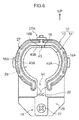
- valve section 16 of the flap 14 has a substantially elliptical shape as an example of a substantially circular shape; however, as in another exemplary embodiment illustrated in Fig. 6 , the shape of the valve section 16 of the flap 14 may instead be a shape including the straight line portion 16B at a portion of a circular shaped outer periphery as an example of a substantially circular shape. Three or more of the coupling sections 20 may also be provided.
- the oil separator of the present invention may be applied as a separator disposed in an inner portion of a head cover of an automobile engine in order to separate oil contained in blow-by gas generated in an inner portion of the automobile engine, or may be applied to an internal combustion engine other than an automobile engine.
- the oil separator of the present invention may be provided to a component, other than the head cover, partway along the flow path of the blow-by gas.
Landscapes
- Engineering & Computer Science (AREA)
- Mechanical Engineering (AREA)
- General Engineering & Computer Science (AREA)
- Lubrication Details And Ventilation Of Internal Combustion Engines (AREA)
Abstract
Description
- The present invention relates to an oil separator, and relates in particular to an oil separator that traps oil mist contained in blow-by gas generated inside an engine crankcase of an internal combustion engine such as an automobile engine.
- An oil separator described in the specification of European Patent
(EP) No. 1062162 , for example, is known as this conventional type of oil separator. This oil separator includes a wall portion that is at a downstream side of a circular shaped elastic tongue piece (flap), attached to a flow path of the blow-by gas in a cantilevered state, and that runs along an outer periphery of the elastic tongue piece. Oil mist contained in the blow-by gas can be captured by a slight loss in pressure due to the blow-by gas that has pressed open and flowed past the elastic tongue piece striking the wall portion. - However, in the oil separator described in the specification of
EP. No. 1062162 , an outer peripheral portion of the elastic tongue piece which the blow-by gas passes is configured in a circular arc shape, and the wall portion is also formed in a circular arc shape along the outer periphery of the elastic tongue piece. Thus, even if the wall portion is designed to secure a minimum flow path cross-sectional area required in order for the blow-by gas to pass through, and to be at the closest position to the outer periphery of the elastic tongue piece, the blow-by gas that has passed the outer periphery of the elastic tongue piece is dispersed in a radiating shape in the peripheral direction of the circular arc, such that the flow speed of the blow-by gas prior to striking the wall portion is reduced. There is accordingly a reduction in efficiency in capturing oil mist. - In consideration of the above circumstances, an object of the present invention is to obtain an oil separator capable of improving performance in capturing oil mist.
- An oil separator of a first aspect of the present invention includes: an oil separator main body that is formed with a gas flow path between a gas introduction port that introduces blow-by gas and a gas discharge port that discharges the blow-by gas; a flap that is provided extending along a direction orthogonal to the gas flow path, that opens and closes the gas flow path, and that includes a substantially circular shaped valve section including a straight line portion of a substantially straight line shape at a portion of an outer periphery of the valve section; and a first impact wall for capturing oil, that is provided along the outer periphery of the valve section at a downstream side of the valve section in the gas flow path, that includes a straight line portion of a substantially straight line shape along the straight line portion of the valve section, and that is impacted by the blow-by gas flowing out from a peripheral edge of the valve section.
- In the oil separator of the first aspect, blow-by gas that has been introduced through the gas introduction port of the oil separator main body flows into the gas flow path formed between the gas introduction port and the gas discharge port. The blow-by gas (hereafter referred to as "flow of gas") presses open and flows past the valve section of the flap provided extending along a direction orthogonal to the gas flow path, and hits the first impact wall provided at the outer periphery of the valve section at the downstream side of the valve section of the flap, such that oil (oil in mist form) is captured. The valve section of the flap has a substantially circular shape including the straight line portion of substantially straight line shape at a portion of the outer periphery of the valve section, and a portion of the first impact wall is the straight line portion that is of substantially straight line shape along the straight line portion of the valve section. Thus, the flow of gas that has passed the straight line portion at the outer periphery of the valve section of the flap flows toward the straight line portion of the opposing first impact wall without being dispersed in the peripheral direction of a circular arc portion, unlike the flow of gas at a circular arc portion, thereby enabling a reduction in the flow speed of the blow-by gas prior to striking the straight line portion of the first impact wall to be suppressed. Thus, the blow-by gas for which a reduction in flow speed has been suppressed strikes the location of the first impact wall that is of substantially straight line shape (the straight line portion), thereby improving performance in capturing oil mist.
- An oil separator of a second aspect of the present invention is the oil separator of the first aspect, wherein a fixing section for fixing the flap to the gas flow path is formed at a location at an opposite side of the flap from the straight line portion.
- In the oil separator of the second aspect, when the valve section of the flap has been pressed open by the flow of gas, the location of the valve section at the opposite side of the flap from the fixing section opens wider than other locations, such that the flow of gas is greater than at other locations. Thus, efficiency in capturing oil mist is further improved by having the straight line portion of the valve section of the flap at the location at the opposite side to the fixing section of the flap.
- An oil separator of a third aspect of the present invention is the oil separator of the second aspect, wherein the valve section and the fixing section are coupled together by two coupling sections that project out from the valve section toward the fixing section and that are separated along an outer peripheral direction of the valve section, and a second impact wall is formed in a substantially straight line shape at a location corresponding to somewhere between the two coupling sections.
- In the oil separator of the third aspect, when the valve section of the flap has been pressed open by the flow of gas, the flow of gas flows out between the two coupling sections that couple the valve section and the fixing section together. The flow of gas impacts the second impact wall formed in a substantially straight line shape at a location corresponding to the separation between the two coupling sections, such that oil mist is captured. Thus, performance in capturing oil mist is further improved.
- An oil separator of a fourth aspect of the present invention is the oil separator of any one of the first aspect to the third aspect, wherein the valve section of the flap is disposed along a substantially vertical direction, the straight line portion of the first impact wall is disposed along a substantially horizontal direction, and an opening section for discharging captured oil is formed below the first impact wall.
- In the oil separator of the fourth aspect, the flow of gas presses open and flows past the valve section of the flap disposed along the substantially vertical direction and hits the straight line portion of the first impact wall disposed along the substantially horizontal direction, such that oil is captured. Oil captured at the first impact wall drops under its own weight and is discharged through the opening section formed below the first impact wall. Recovery of oil is therefore easy.
- An oil separator of a fifth aspect of the present invention is the oil separator of any one of the first aspect to the fourth aspect, further including an attachment portion that is formed at an outer peripheral portion of the oil separator main body and that is fixed to an inner portion of an engine head cover.
- In the oil separator of the fifth aspect of the present invention, the oil separator can be fixed to the inner portion of the engine head cover by the attachment portion formed to the outer peripheral portion of the oil separator main body. This enables the oil separator to be easily disposed at an inner portion of the engine head cover.
- The oil separator of the first aspect of the present invention has the above configuration, thereby enabling performance in capturing oil mist to be improved.
- The oil separator of the second aspect of the present invention has the above configuration, thereby enabling performance in capturing oil mist to be further improved.
- The oil separator of the third aspect of the present invention has the above configuration, thereby enabling performance in capturing oil mist to be further improved.
- The oil separator of the fourth aspect of the present invention has the above configuration, thereby enabling oil to be easily recovered.
- The oil separator of the fifth aspect of the present invention has the above configuration, thereby enabling the oil separator to be easily disposed at an inner portion of the engine head cover.
-
-
Fig. 1 is a perspective view illustrating an external appearance of an oil separator according to an exemplary embodiment of the present invention. -
Fig. 2 is an exploded perspective view illustrating an oil separator according to an exemplary embodiment of the present invention. -
Fig. 3 is a face-on view illustrating an oil separator according to an exemplary embodiment of the present invention. -
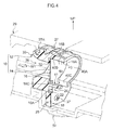
Fig. 4 is a perspective view illustrating part of an oil separator according to an exemplary embodiment of the present invention, sectioned along line 4-4 inFig. 3 . -
Fig. 5 is a cross-section illustrating an operating state of an oil separator according to an exemplary embodiment of the present invention, sectioned along line 5-5 inFig. 3 . -
Fig. 6 is a face-on view illustrating an oil separator according to another exemplary embodiment of the present invention. - Explanation follows regarding an oil separator according to an exemplary embodiment of the present invention, with reference to
Fig. 1 to Fig. 5 . Note that the arrow UP in the drawings indicates the upper direction in a vertical direction, this being the upper side of the oil separator. - As illustrated in
Fig. 1 , anoil separator 10 of the present exemplary embodiment includes an oil separatormain body 12 and aflap 14. - As illustrated in
Fig. 2 , as an example, theflap 14 is configured by a thin metal plate, and includes avalve section 16, and afixing section 18 for fixing theflap 14 to a gas flow path. Thevalve section 16 and thefixing section 18 are coupled together bycoupling sections 20. When theflap 14 undergoes elastic deformation under the pressure of a flow of gas, thevalve section 16 is capable of moving between a closed position illustrated by double-dotted dashed lines and an open position illustrated by solid lines inFig. 5 . - As illustrated in
Fig. 3 , thevalve section 16 of theflap 14 is configured in a substantially elliptical shape, this being an example of a substantially circular shape with its length direction along the left-right direction, and left and right outer peripheral portions respectively configuresemicircular arc portions 16A. A location at an upper side outer peripheral portion between thesemicircular arc portions 16A configures astraight line portion 16B in a straight line along the left-right direction, this being the peripheral direction, and L1 is a length of thestraight line portion 16B along the left-right direction. An outer peripheral portion at the opposite side of thevalve section 16 to thestraight line portion 16B configures astraight line portion 16C in a straight line along the left-right direction. The left and right pair ofcoupling sections 20 are respectively formed projecting downward from the vicinity of both end portions at the left and right of thestraight line portion 16C. - As illustrated in
Fig. 2 , thefixing section 18 of theflap 14 is formed at a location of an outer peripheral portion of thevalve section 16 at the opposite side to thestraight line portion 16B. Thefixing section 18 of theflap 14 is configured in a rectangular shape with its length direction along the left-right direction, and lower ends of the left and right pair ofcoupling sections 20 are coupled to an upper side outerperipheral portion 18A of thefixing section 18. A rectangular shapedcutout 22 is thereby formed between the left and right pair ofcoupling sections 20. A pair of circularshaped attachment holes 24 are formed in thefixing section 18 with a specific separation in the left-right direction therebetween. - As illustrated in
Fig. 4 , the oil separatormain body 12 includes aflap fixing section 25 to which theflap 14 is fixed, and aframe section 27 forming agas flow path 28 through which blow-by gas (the arrow W1 inFig. 5 ) flows. Anengagement portion 27A, serving as an attachment portion for fixing theoil separator 10 to an inner portion of anengine head cover 29, is formed at an outer peripheral portion of theframe section 27. - As illustrated in
Fig. 5 , thegas flow path 28 of the oil separatormain body 12 is formed in a straight line between agas introduction port 30 for introducing blow-by gas and agas discharge port 32 for discharging blow-by gas, and an outer peripheral portion of thegas flow path 28 configures theframe section 27. Theflap fixing section 25 of the oil separatormain body 12 is formed projecting out at the lower side of theframe section 27 of the oil separatormain body 12. - As illustrated in
Fig. 2 , a pair of attachment holes 39 are formed in theflap fixing section 25 with a specific separation in the left-right direction therebetween. Theflap 14 is fixed to the oil separatormain body 12 by passing fixing members such asscrews 37 through the attachment holes 24 and the attachment holes 39 and fastening to female thread portions formed in the attachment holes 39 in a state in which the fixingsection 18 of theflap 14 has abutted theflap fixing section 25. - As illustrated in
Fig. 4 , animpact wall 40 is formed projecting toward a downstream direction (the right direction inFig. 5 ) at the downstream side of theflap 14 in thegas flow path 28 of the oil separatormain body 12. Note that "downstream" in the present exemplary embodiment refers to downstream in the direction in which the blow-by gas flows. - As illustrated in
Fig. 3 , theimpact wall 40 of the oil separatormain body 12 is provided along the outer periphery of thevalve section 16 of theflap 14. To explain more specifically, theimpact wall 40 is configured in a substantially elliptical shape with its length direction along the left-right direction, and left and right outer peripheral portions configuresemicircular arc portions 40A. A location at an upper side outer peripheral portion between thesemicircular arc portions 40A configures astraight line portion 40B in a straight line, and L1 is the length of thestraight line portion 40B along the left-right direction. Animpact wall 41 is formed at a left-right direction central portion at a location facing thestraight line portion 40B of theimpact wall 40. Theimpact wall 41 extends in a straight line in the left-right direction along thestraight line portion 16C of thevalve section 16, and passes through thecutout 22 of theflap 14. Note that theimpact wall 40 of the present exemplary embodiment is an example of a first impact wall of the present invention, and theimpact wall 41 of the present exemplary embodiment is an example of a second impact wall of the present invention. - Thus, as illustrated in
Fig. 5 , the flow of gas (the arrow W1 inFig. 5 ) presses open and flows, as illustrated by the solid lines inFig. 5 , through thevalve section 16 of theflap 14 provided extending along a direction orthogonal to thegas flow path 28. When this occurs, the flow of gas (the arrows W2 to W4 inFig. 5 ) hits theimpact wall 40 and theimpact wall 41 provided along the outer peripheral portion of thevalve section 16 at the downstream side of thevalve section 16 of theflap 14, such that oil is captured. Blow-by gas that has passed thestraight line portion 16B at the outer periphery of thevalve section 16 of the flap 14 (the arrow W2 inFig. 5 ) flows toward the opposingstraight line portion 40B of theimpact wall 40, without being dispersed in the peripheral direction of thesemicircular arc portions 40A, unlike the flow of gas at thesemicircular arc portions 40A (the arrow W3 inFig. 5 ). - Note that in the present exemplary embodiment, the
valve section 16 of theflap 14 is disposed along the vertical direction, and thestraight line portion 40B of theimpact wall 40 and theimpact wall 41 are disposed along the horizontal direction. - As illustrated in
Fig. 3 , openingsections 50 for discharging captured oil are formed below theimpact wall 40 and theimpact wall 41 in the oil separatormain body 12. To explain more specifically, a left and right pair of the openingsections 50 for discharging captured oil from the oil separatormain body 12 are respectively formed between both left-right direction ends 41A of theimpact wall 41 and peripheraldirection end portions 40C of theimpact wall 40, the peripheraldirection end portions 40C of theimpact wall 40 being provided extending downward. Thecoupling sections 20 of theflap 14 pass through the openingsections 50. - Thus, as illustrated by the arrow S1 in
Fig. 5 , oil that has pooled at inner peripheral portions of theimpact wall 40 and theimpact wall 41 of theoil separator 10 passes through the openingsections 50 and is discharged from the oil separatormain body 12, and is then recovered through adrain valve 54 as illustrated by the arrow S2. - Explanation follows regarding operation and advantageous effects of the present exemplary embodiment.
- In the
oil separator 10 of the present exemplary embodiment, as illustrated inFig. 5 , blow-by gas that has been introduced to an inner portion of the oil separatormain body 12 through the gas introduction port 30 (the arrow W1 inFig. 5 ) flows into thegas flow path 28 formed between thegas introduction port 30 and thegas discharge port 32. The flow of gas presses open and flows, as illustrated by the solid lines inFig. 5 , through thevalve section 16 of theflap 14 provided extending along a direction orthogonal to thegas flow path 28, and hits theimpact wall 40 provided along the outer periphery of thevalve section 16 at the downstream side of thevalve section 16 of theflap 14, such that oil that has formed water droplets is captured. - In the present exemplary embodiment, a portion of the outer periphery of the
valve section 16 of theflap 14 includes thestraight line portion 16B in a straight line, and thestraight line portion 40B of theimpact wall 40 is provided along thestraight line portion 16B. Thus, blow-by gas that has passed thestraight line portion 16B at the outer periphery of thevalve section 16 of the flap 14 (the arrow W2 inFig. 5 ) flows toward the opposingstraight line portion 40B of theimpact wall 40 without being dispersed in the peripheral direction of thesemicircular arc portions 40A, unlike the flow of gas at thesemicircular arc portions 40A (the arrow W3 inFig. 5 ), thereby enabling a reduction in the flow speed of the blow-by gas prior to striking thestraight line portion 40B of theimpact wall 40 to be suppressed. Thus, the blow-by gas for which a reduction in flow speed has been suppressed strikes thestraight line portion 40B of theimpact wall 40, thereby improving performance in capturing oil mist. - Note that, in cases in which the surface area of the
valve section 16 of theflap 14 is uniform, and the shape of thevalve section 16 is rectangular with straight line portions about the entire outer periphery thereof, there is an increase in the pressure loss in the flow of gas when thevalve section 16 is opened. Thus, by configuring thevalve section 16 in a substantially elliptical shape including thestraight line portion 40B in theoil separator 10 of the present exemplary embodiment, the pressure loss in the flow of gas is reduced, and performance in capturing oil mist can be improved. Since the configuration is not one in which respective distances between thevalve section 16 of theflap 14, and theimpact wall 40 and theimpact wall 41 is decreased to improve performance in capturing oil mist, the pressure loss in the flow of gas is reduced and performance in capturing oil mist is improved, while securing tolerance (the difference between a maximum dimension and minimum dimension permitted while machining). - In the
oil separator 10 of the present exemplary embodiment, thevalve section 16 of theflap 14 includes thestraight line portion 16B at the upper side outer peripheral portion thereof, and thestraight line portion 40B is formed at the upper side outer peripheral portion of theimpact wall 40 of theframe section 27 in the oil separatormain body 12. This enables an up-down direction dimension of theoil separator 10 to be made smaller. This also enables an up-down direction dimension of the engine head cover 29 in which theoil separator 10 is disposed to be made smaller. - In the
oil separator 10 of the present exemplary embodiment, the fixingsection 18 of theflap 14 is formed at a location of the outer peripheral portion of thevalve section 16 at the opposite side to thestraight line portion 16B. Thus, when thevalve section 16 of theflap 14 has been pressed open by the flow of gas (the arrow W2 inFig. 5 ), thestraight line portion 16B of thevalve section 16 that opposes the fixingsection 18 opens wider than other locations at the outer peripheral portion, and the flow of gas (the arrow W2 inFig. 5 ) is greater than the flow of gas at other locations at the outer peripheral portion (the arrows W3, W4 inFig. 5 ). Thus, efficiency in capturing oil mist is further improved by having thestraight line portion 16B of thevalve section 16 at the location opposing the fixingsection 18 of theflap 14. - In the
oil separator 10 of the present exemplary embodiment, the left and right pair of the twocoupling sections 20 project out from thevalve section 16 of theflap 14 toward the fixingsection 18 with a separation in the left-right direction therebetween, and theimpact wall 41 is also formed at an inner portion of thecutout 22 formed between thecoupling sections 20. Thus, when thevalve section 16 of theflap 14 has been pressed open by the flow of gas, the flow of gas that has flowed out between the twocoupling sections 20 impacts theimpact wall 41, such that oil mist is captured. Thus, performance in capturing oil mist is further improved. - In the
oil separator 10 of the present exemplary embodiment, the flow of gas (the arrow W1 inFig. 5 ) presses open and flows through thevalve section 16 of theflap 14 disposed along the substantially vertical direction and hits thestraight line portion 40B of theimpact wall 40 disposed along the substantially horizontal direction, such that oil is captured. Oil captured at theimpact wall 40 and the impact wall 41 (the arrow S1 inFig. 5 ) drops under its own weight, and is discharged through the left and right pair of openingsections 50 formed at a lower portion of theimpact wall 40 to be recovered from thedrain valve 54. Recovery of oil is therefore easy. - In the present exemplary embodiment, the
oil separator 10 can be fixed to an inner portion of theengine head cover 29 by engaging theengagement portion 27A formed to an outer peripheral portion of the oil separatormain body 12 with theengine head cover 29. This enables theoil separator 10 to be easily disposed inside theengine head cover 29. - The present invention has been explained in detail above with reference to a particular exemplary embodiment; however, the present invention is not limited to the above exemplary embodiment, and it would be obvious to a skilled practitioner that various other exemplary embodiments may be implemented within a range of the present invention. For example, in the above exemplary embodiment, the
straight line portion 16B of theflap 14, thestraight line portion 40B of theimpact wall 40, and theimpact wall 41 are each configured in a straight line; however, thestraight line portion 16B, thestraight line portion 40B, and theimpact wall 41 may each be configured in a substantially straight line shape that is close to a straight line, but curves slightly. In the above exemplary embodiment, thevalve section 16 of theflap 14 has a substantially elliptical shape as an example of a substantially circular shape; however, as in another exemplary embodiment illustrated inFig. 6 , the shape of thevalve section 16 of theflap 14 may instead be a shape including thestraight line portion 16B at a portion of a circular shaped outer periphery as an example of a substantially circular shape. Three or more of thecoupling sections 20 may also be provided. - The oil separator of the present invention may be applied as a separator disposed in an inner portion of a head cover of an automobile engine in order to separate oil contained in blow-by gas generated in an inner portion of the automobile engine, or may be applied to an internal combustion engine other than an automobile engine. The oil separator of the present invention may be provided to a component, other than the head cover, partway along the flow path of the blow-by gas.
- The entire content of the disclosure of Japanese Patent Application No.
2013-264479 filed December 20, 2013 - All publications, patent applications and technical standards mentioned in the present specification are incorporated by reference in the present specification to the same extent as if the individual publication, patent application, or technical standard was specifically and individually indicated to be incorporated by reference.
Claims (5)
- An oil separator comprising:an oil separator main body that is formed with a gas flow path between a gas introduction port that introduces blow-by gas and a gas discharge port that discharges the blow-by gas;a flap that is provided extending along a direction orthogonal to the gas flow path, that opens and closes the gas flow path, and that includes a substantially circular shaped valve section including a straight line portion of a substantially straight line shape at a portion of an outer periphery of the valve section; anda first impact wall for capturing oil, that is provided along the outer periphery of the valve section at a downstream side of the valve section in the gas flow path, that includes a straight line portion of a substantially straight line shape along the straight line portion of the valve section, and that is impacted by the blow-by gas flowing out from a peripheral edge of the valve section.
- The oil separator of claim 1, wherein a fixing section for fixing the flap to the gas flow path is formed at a location at an opposite side of the flap from the straight line portion.
- The oil separator of claim 2, wherein:the valve section and the fixing section are coupled together by two coupling sections that project out from the valve section toward the fixing section and that are separated along an outer peripheral direction of the valve section; anda second impact wall is formed in a substantially straight line shape at a location corresponding to somewhere between the two coupling sections.
- The oil separator of any one of claims 1 to 3, wherein:the valve section of the flap is disposed along a substantially vertical direction;the straight line portion of the first impact wall is disposed along a substantially horizontal direction; andan opening section for discharging captured oil is formed below the first impact wall.
- The oil separator of any one of claims 1 to 4, further comprising an attachment portion that is formed at an outer peripheral portion of the oil separator main body and that is fixed to an inner portion of an engine head cover.
Applications Claiming Priority (2)
| Application Number | Priority Date | Filing Date | Title |
|---|---|---|---|
| JP2013264479A JP6178717B2 (en) | 2013-12-20 | 2013-12-20 | Oil separator |
| PCT/JP2014/082324 WO2015093327A1 (en) | 2013-12-20 | 2014-12-05 | Oil separator |
Publications (3)
| Publication Number | Publication Date |
|---|---|
| EP3085907A1 true EP3085907A1 (en) | 2016-10-26 |
| EP3085907A4 EP3085907A4 (en) | 2017-09-13 |
| EP3085907B1 EP3085907B1 (en) | 2019-08-14 |
Family
ID=53402676
Family Applications (1)
| Application Number | Title | Priority Date | Filing Date |
|---|---|---|---|
| EP14870727.6A Active EP3085907B1 (en) | 2013-12-20 | 2014-12-05 | Oil separator |
Country Status (6)
| Country | Link |
|---|---|
| US (1) | US10385743B2 (en) |
| EP (1) | EP3085907B1 (en) |
| JP (1) | JP6178717B2 (en) |
| KR (2) | KR20170086683A (en) |
| CN (1) | CN105829669B (en) |
| WO (1) | WO2015093327A1 (en) |
Families Citing this family (4)
| Publication number | Priority date | Publication date | Assignee | Title |
|---|---|---|---|---|
| DE202014006149U1 (en) * | 2014-07-29 | 2015-07-31 | Reinz-Dichtungs-Gmbh | Device for separating oil droplets and / or oil mist |
| DE102016100419B4 (en) * | 2016-01-12 | 2019-07-04 | BRUSS Sealing Systems GmbH | Oil separation device for the crankcase ventilation of an internal combustion engine |
| CN105626192B (en) * | 2016-02-15 | 2018-02-16 | 东风朝阳朝柴动力环保科技有限公司 | Multifunctional mask respirator holder device with gas channel |
| CN107143401B (en) * | 2017-06-20 | 2023-05-12 | 宁波市鄞州德来特技术有限公司 | Oil-gas separator structure and engine |
Family Cites Families (13)
| Publication number | Priority date | Publication date | Assignee | Title |
|---|---|---|---|---|
| WO1999030979A1 (en) | 1997-12-17 | 1999-06-24 | The Popstraw Company, Llc | Beverage container with self-contained drinking straw |
| JP2001280112A (en) * | 2000-03-31 | 2001-10-10 | Honda Motor Co Ltd | Gas-liquid separation chamber for outboard engine |
| US6412478B1 (en) * | 2001-01-02 | 2002-07-02 | Generac Power Systems, Inc. | Breather for internal combustion engine |
| CN2608694Y (en) * | 2003-02-27 | 2004-03-31 | 洪志才 | Pressure relief aeolian type oil gas separator of internal combustion engine |
| US7080636B2 (en) * | 2003-05-05 | 2006-07-25 | Dichtungstechnik G. Bruss Gmbh & Co. Kg | Oil separating device for a combustion engine |
| US7678169B1 (en) * | 2006-07-12 | 2010-03-16 | Cummins Filtration Ip Inc. | Oil fill cap with air/oil separator |
| DE102006051143B4 (en) * | 2006-10-30 | 2010-01-21 | Reinz-Dichtungs-Gmbh | Adaptive oil separator |
| DE102007062098A1 (en) | 2007-12-21 | 2009-06-25 | Mahle International Gmbh | Oil Mist Separators |
| JP5072719B2 (en) * | 2008-06-05 | 2012-11-14 | 本田技研工業株式会社 | Engine breather equipment |
| CN201280963Y (en) * | 2008-10-07 | 2009-07-29 | 浙江方圆机电设备制造有限公司 | Oil-gas separator |
| JP5304542B2 (en) * | 2009-08-28 | 2013-10-02 | トヨタ紡織株式会社 | Oil mist separator |
| JP5432856B2 (en) * | 2010-08-06 | 2014-03-05 | トヨタ自動車株式会社 | Oil separator arrangement structure |
| JP6135102B2 (en) * | 2012-11-22 | 2017-05-31 | アイシン精機株式会社 | Blow-by gas reduction device |
-
2013
- 2013-12-20 JP JP2013264479A patent/JP6178717B2/en active Active
-
2014
- 2014-12-05 CN CN201480068714.4A patent/CN105829669B/en active Active
- 2014-12-05 WO PCT/JP2014/082324 patent/WO2015093327A1/en not_active Ceased
- 2014-12-05 EP EP14870727.6A patent/EP3085907B1/en active Active
- 2014-12-05 KR KR1020177019812A patent/KR20170086683A/en not_active Withdrawn
- 2014-12-05 KR KR1020167018071A patent/KR101957002B1/en not_active Expired - Fee Related
- 2014-12-05 US US15/105,390 patent/US10385743B2/en active Active
Also Published As
| Publication number | Publication date |
|---|---|
| EP3085907A4 (en) | 2017-09-13 |
| JP6178717B2 (en) | 2017-08-09 |
| CN105829669B (en) | 2018-11-02 |
| US20160312672A1 (en) | 2016-10-27 |
| EP3085907B1 (en) | 2019-08-14 |
| JP2015121123A (en) | 2015-07-02 |
| KR20160097255A (en) | 2016-08-17 |
| KR101957002B1 (en) | 2019-03-11 |
| KR20170086683A (en) | 2017-07-26 |
| US10385743B2 (en) | 2019-08-20 |
| CN105829669A (en) | 2016-08-03 |
| WO2015093327A1 (en) | 2015-06-25 |
Similar Documents
| Publication | Publication Date | Title |
|---|---|---|
| EP3085907B1 (en) | Oil separator | |
| JP5953938B2 (en) | Oil separator | |
| JP4169763B2 (en) | Oil separator for blow-by gas | |
| JP6146202B2 (en) | Oil mist separator | |
| US9598992B2 (en) | Separation device for an aerosol stream | |
| US10145278B2 (en) | Blow-by gas passage structure | |
| EP2913492B1 (en) | Blowby gas processing device of internal combustion engine | |
| JP2010144676A (en) | Oil separator of internal combustion engine | |
| CN110131013B (en) | Oil separator | |
| EP3388647B1 (en) | Secondary air introduction device | |
| JP6065754B2 (en) | Oil mist separator | |
| JP2009047141A (en) | Engine oil separator | |
| JP2012122370A (en) | Oil mist separator of blow-by gas | |
| JP2008121478A (en) | Blowby flow channel structure of internal combustion engine | |
| WO2017122724A1 (en) | Oil separator structure | |
| JP6329802B2 (en) | Internal combustion engine | |
| JP2018197523A (en) | Oil mist separator | |
| US11105232B2 (en) | Blow-by gas conduit | |
| JP2018193944A (en) | Blow-by gas treatment device for internal combustion engine | |
| JP5473863B2 (en) | Seal structure of oil separator and cylinder head cover | |
| US20150096272A1 (en) | Oil separator for separating oil from blow-by gas of internal combustion engine | |
| KR101713441B1 (en) | Intake manifold | |
| JP2007009827A (en) | Internal combustion engine | |
| JP2016217342A (en) | Blowby gas passage structure and manufacturing method thereof | |
| JP2015169125A (en) | Closed breather system |
Legal Events
| Date | Code | Title | Description |
|---|---|---|---|
| PUAI | Public reference made under article 153(3) epc to a published international application that has entered the european phase |
Free format text: ORIGINAL CODE: 0009012 |
|
| 17P | Request for examination filed |
Effective date: 20160622 |
|
| AK | Designated contracting states |
Kind code of ref document: A1 Designated state(s): AL AT BE BG CH CY CZ DE DK EE ES FI FR GB GR HR HU IE IS IT LI LT LU LV MC MK MT NL NO PL PT RO RS SE SI SK SM TR |
|
| AX | Request for extension of the european patent |
Extension state: BA ME |
|
| DAX | Request for extension of the european patent (deleted) | ||
| A4 | Supplementary search report drawn up and despatched |
Effective date: 20170811 |
|
| RIC1 | Information provided on ipc code assigned before grant |
Ipc: F01M 13/04 20060101AFI20170807BHEP Ipc: F01M 13/00 20060101ALI20170807BHEP |
|
| STAA | Information on the status of an ep patent application or granted ep patent |
Free format text: STATUS: EXAMINATION IS IN PROGRESS |
|
| 17Q | First examination report despatched |
Effective date: 20180423 |
|
| GRAP | Despatch of communication of intention to grant a patent |
Free format text: ORIGINAL CODE: EPIDOSNIGR1 |
|
| STAA | Information on the status of an ep patent application or granted ep patent |
Free format text: STATUS: GRANT OF PATENT IS INTENDED |
|
| INTG | Intention to grant announced |
Effective date: 20190319 |
|
| GRAS | Grant fee paid |
Free format text: ORIGINAL CODE: EPIDOSNIGR3 |
|
| GRAA | (expected) grant |
Free format text: ORIGINAL CODE: 0009210 |
|
| STAA | Information on the status of an ep patent application or granted ep patent |
Free format text: STATUS: THE PATENT HAS BEEN GRANTED |
|
| AK | Designated contracting states |
Kind code of ref document: B1 Designated state(s): AL AT BE BG CH CY CZ DE DK EE ES FI FR GB GR HR HU IE IS IT LI LT LU LV MC MK MT NL NO PL PT RO RS SE SI SK SM TR |
|
| REG | Reference to a national code |
Ref country code: GB Ref legal event code: FG4D |
|
| REG | Reference to a national code |
Ref country code: CH Ref legal event code: EP Ref country code: AT Ref legal event code: REF Ref document number: 1167289 Country of ref document: AT Kind code of ref document: T Effective date: 20190815 |
|
| REG | Reference to a national code |
Ref country code: IE Ref legal event code: FG4D |
|
| REG | Reference to a national code |
Ref country code: DE Ref legal event code: R096 Ref document number: 602014051933 Country of ref document: DE |
|
| REG | Reference to a national code |
Ref country code: NL Ref legal event code: MP Effective date: 20190814 |
|
| REG | Reference to a national code |
Ref country code: LT Ref legal event code: MG4D |
|
| PG25 | Lapsed in a contracting state [announced via postgrant information from national office to epo] |
Ref country code: LT Free format text: LAPSE BECAUSE OF FAILURE TO SUBMIT A TRANSLATION OF THE DESCRIPTION OR TO PAY THE FEE WITHIN THE PRESCRIBED TIME-LIMIT Effective date: 20190814 Ref country code: HR Free format text: LAPSE BECAUSE OF FAILURE TO SUBMIT A TRANSLATION OF THE DESCRIPTION OR TO PAY THE FEE WITHIN THE PRESCRIBED TIME-LIMIT Effective date: 20190814 Ref country code: NO Free format text: LAPSE BECAUSE OF FAILURE TO SUBMIT A TRANSLATION OF THE DESCRIPTION OR TO PAY THE FEE WITHIN THE PRESCRIBED TIME-LIMIT Effective date: 20191114 Ref country code: SE Free format text: LAPSE BECAUSE OF FAILURE TO SUBMIT A TRANSLATION OF THE DESCRIPTION OR TO PAY THE FEE WITHIN THE PRESCRIBED TIME-LIMIT Effective date: 20190814 Ref country code: FI Free format text: LAPSE BECAUSE OF FAILURE TO SUBMIT A TRANSLATION OF THE DESCRIPTION OR TO PAY THE FEE WITHIN THE PRESCRIBED TIME-LIMIT Effective date: 20190814 Ref country code: PT Free format text: LAPSE BECAUSE OF FAILURE TO SUBMIT A TRANSLATION OF THE DESCRIPTION OR TO PAY THE FEE WITHIN THE PRESCRIBED TIME-LIMIT Effective date: 20191216 Ref country code: BG Free format text: LAPSE BECAUSE OF FAILURE TO SUBMIT A TRANSLATION OF THE DESCRIPTION OR TO PAY THE FEE WITHIN THE PRESCRIBED TIME-LIMIT Effective date: 20191114 Ref country code: NL Free format text: LAPSE BECAUSE OF FAILURE TO SUBMIT A TRANSLATION OF THE DESCRIPTION OR TO PAY THE FEE WITHIN THE PRESCRIBED TIME-LIMIT Effective date: 20190814 |
|
| REG | Reference to a national code |
Ref country code: AT Ref legal event code: MK05 Ref document number: 1167289 Country of ref document: AT Kind code of ref document: T Effective date: 20190814 |
|
| PG25 | Lapsed in a contracting state [announced via postgrant information from national office to epo] |
Ref country code: IS Free format text: LAPSE BECAUSE OF FAILURE TO SUBMIT A TRANSLATION OF THE DESCRIPTION OR TO PAY THE FEE WITHIN THE PRESCRIBED TIME-LIMIT Effective date: 20191214 Ref country code: RS Free format text: LAPSE BECAUSE OF FAILURE TO SUBMIT A TRANSLATION OF THE DESCRIPTION OR TO PAY THE FEE WITHIN THE PRESCRIBED TIME-LIMIT Effective date: 20190814 Ref country code: GR Free format text: LAPSE BECAUSE OF FAILURE TO SUBMIT A TRANSLATION OF THE DESCRIPTION OR TO PAY THE FEE WITHIN THE PRESCRIBED TIME-LIMIT Effective date: 20191115 Ref country code: AL Free format text: LAPSE BECAUSE OF FAILURE TO SUBMIT A TRANSLATION OF THE DESCRIPTION OR TO PAY THE FEE WITHIN THE PRESCRIBED TIME-LIMIT Effective date: 20190814 Ref country code: LV Free format text: LAPSE BECAUSE OF FAILURE TO SUBMIT A TRANSLATION OF THE DESCRIPTION OR TO PAY THE FEE WITHIN THE PRESCRIBED TIME-LIMIT Effective date: 20190814 Ref country code: ES Free format text: LAPSE BECAUSE OF FAILURE TO SUBMIT A TRANSLATION OF THE DESCRIPTION OR TO PAY THE FEE WITHIN THE PRESCRIBED TIME-LIMIT Effective date: 20190814 |
|
| PG25 | Lapsed in a contracting state [announced via postgrant information from national office to epo] |
Ref country code: TR Free format text: LAPSE BECAUSE OF FAILURE TO SUBMIT A TRANSLATION OF THE DESCRIPTION OR TO PAY THE FEE WITHIN THE PRESCRIBED TIME-LIMIT Effective date: 20190814 |
|
| PG25 | Lapsed in a contracting state [announced via postgrant information from national office to epo] |
Ref country code: AT Free format text: LAPSE BECAUSE OF FAILURE TO SUBMIT A TRANSLATION OF THE DESCRIPTION OR TO PAY THE FEE WITHIN THE PRESCRIBED TIME-LIMIT Effective date: 20190814 Ref country code: DK Free format text: LAPSE BECAUSE OF FAILURE TO SUBMIT A TRANSLATION OF THE DESCRIPTION OR TO PAY THE FEE WITHIN THE PRESCRIBED TIME-LIMIT Effective date: 20190814 Ref country code: PL Free format text: LAPSE BECAUSE OF FAILURE TO SUBMIT A TRANSLATION OF THE DESCRIPTION OR TO PAY THE FEE WITHIN THE PRESCRIBED TIME-LIMIT Effective date: 20190814 Ref country code: RO Free format text: LAPSE BECAUSE OF FAILURE TO SUBMIT A TRANSLATION OF THE DESCRIPTION OR TO PAY THE FEE WITHIN THE PRESCRIBED TIME-LIMIT Effective date: 20190814 Ref country code: EE Free format text: LAPSE BECAUSE OF FAILURE TO SUBMIT A TRANSLATION OF THE DESCRIPTION OR TO PAY THE FEE WITHIN THE PRESCRIBED TIME-LIMIT Effective date: 20190814 Ref country code: IT Free format text: LAPSE BECAUSE OF FAILURE TO SUBMIT A TRANSLATION OF THE DESCRIPTION OR TO PAY THE FEE WITHIN THE PRESCRIBED TIME-LIMIT Effective date: 20190814 |
|
| PG25 | Lapsed in a contracting state [announced via postgrant information from national office to epo] |
Ref country code: SM Free format text: LAPSE BECAUSE OF FAILURE TO SUBMIT A TRANSLATION OF THE DESCRIPTION OR TO PAY THE FEE WITHIN THE PRESCRIBED TIME-LIMIT Effective date: 20190814 Ref country code: IS Free format text: LAPSE BECAUSE OF FAILURE TO SUBMIT A TRANSLATION OF THE DESCRIPTION OR TO PAY THE FEE WITHIN THE PRESCRIBED TIME-LIMIT Effective date: 20200224 Ref country code: CZ Free format text: LAPSE BECAUSE OF FAILURE TO SUBMIT A TRANSLATION OF THE DESCRIPTION OR TO PAY THE FEE WITHIN THE PRESCRIBED TIME-LIMIT Effective date: 20190814 Ref country code: SK Free format text: LAPSE BECAUSE OF FAILURE TO SUBMIT A TRANSLATION OF THE DESCRIPTION OR TO PAY THE FEE WITHIN THE PRESCRIBED TIME-LIMIT Effective date: 20190814 |
|
| REG | Reference to a national code |
Ref country code: DE Ref legal event code: R097 Ref document number: 602014051933 Country of ref document: DE |
|
| PLBE | No opposition filed within time limit |
Free format text: ORIGINAL CODE: 0009261 |
|
| STAA | Information on the status of an ep patent application or granted ep patent |
Free format text: STATUS: NO OPPOSITION FILED WITHIN TIME LIMIT |
|
| PG2D | Information on lapse in contracting state deleted |
Ref country code: IS |
|
| REG | Reference to a national code |
Ref country code: CH Ref legal event code: PL |
|
| 26N | No opposition filed |
Effective date: 20200603 |
|
| REG | Reference to a national code |
Ref country code: BE Ref legal event code: MM Effective date: 20191231 |
|
| PG25 | Lapsed in a contracting state [announced via postgrant information from national office to epo] |
Ref country code: MC Free format text: LAPSE BECAUSE OF FAILURE TO SUBMIT A TRANSLATION OF THE DESCRIPTION OR TO PAY THE FEE WITHIN THE PRESCRIBED TIME-LIMIT Effective date: 20190814 Ref country code: SI Free format text: LAPSE BECAUSE OF FAILURE TO SUBMIT A TRANSLATION OF THE DESCRIPTION OR TO PAY THE FEE WITHIN THE PRESCRIBED TIME-LIMIT Effective date: 20190814 |
|
| PG25 | Lapsed in a contracting state [announced via postgrant information from national office to epo] |
Ref country code: LU Free format text: LAPSE BECAUSE OF NON-PAYMENT OF DUE FEES Effective date: 20191205 Ref country code: IE Free format text: LAPSE BECAUSE OF NON-PAYMENT OF DUE FEES Effective date: 20191205 |
|
| PG25 | Lapsed in a contracting state [announced via postgrant information from national office to epo] |
Ref country code: LI Free format text: LAPSE BECAUSE OF NON-PAYMENT OF DUE FEES Effective date: 20191231 Ref country code: CH Free format text: LAPSE BECAUSE OF NON-PAYMENT OF DUE FEES Effective date: 20191231 Ref country code: BE Free format text: LAPSE BECAUSE OF NON-PAYMENT OF DUE FEES Effective date: 20191231 |
|
| PGFP | Annual fee paid to national office [announced via postgrant information from national office to epo] |
Ref country code: FR Payment date: 20201112 Year of fee payment: 7 |
|
| PG25 | Lapsed in a contracting state [announced via postgrant information from national office to epo] |
Ref country code: CY Free format text: LAPSE BECAUSE OF FAILURE TO SUBMIT A TRANSLATION OF THE DESCRIPTION OR TO PAY THE FEE WITHIN THE PRESCRIBED TIME-LIMIT Effective date: 20190814 |
|
| PG25 | Lapsed in a contracting state [announced via postgrant information from national office to epo] |
Ref country code: HU Free format text: LAPSE BECAUSE OF FAILURE TO SUBMIT A TRANSLATION OF THE DESCRIPTION OR TO PAY THE FEE WITHIN THE PRESCRIBED TIME-LIMIT; INVALID AB INITIO Effective date: 20141205 Ref country code: MT Free format text: LAPSE BECAUSE OF FAILURE TO SUBMIT A TRANSLATION OF THE DESCRIPTION OR TO PAY THE FEE WITHIN THE PRESCRIBED TIME-LIMIT Effective date: 20190814 |
|
| PG25 | Lapsed in a contracting state [announced via postgrant information from national office to epo] |
Ref country code: MK Free format text: LAPSE BECAUSE OF FAILURE TO SUBMIT A TRANSLATION OF THE DESCRIPTION OR TO PAY THE FEE WITHIN THE PRESCRIBED TIME-LIMIT Effective date: 20190814 |
|
| PG25 | Lapsed in a contracting state [announced via postgrant information from national office to epo] |
Ref country code: FR Free format text: LAPSE BECAUSE OF NON-PAYMENT OF DUE FEES Effective date: 20211231 |
|
| PGFP | Annual fee paid to national office [announced via postgrant information from national office to epo] |
Ref country code: DE Payment date: 20251028 Year of fee payment: 12 |
|
| PGFP | Annual fee paid to national office [announced via postgrant information from national office to epo] |
Ref country code: GB Payment date: 20251030 Year of fee payment: 12 |