EP3085752A1 - Luminescent material - Google Patents
Luminescent material Download PDFInfo
- Publication number
- EP3085752A1 EP3085752A1 EP15164497.8A EP15164497A EP3085752A1 EP 3085752 A1 EP3085752 A1 EP 3085752A1 EP 15164497 A EP15164497 A EP 15164497A EP 3085752 A1 EP3085752 A1 EP 3085752A1
- Authority
- EP
- European Patent Office
- Prior art keywords
- combinations
- luminescent material
- material according
- mixture
- metal
- Prior art date
- Legal status (The legal status is an assumption and is not a legal conclusion. Google has not performed a legal analysis and makes no representation as to the accuracy of the status listed.)
- Granted
Links
Images

Classifications
-
- C—CHEMISTRY; METALLURGY
- C09—DYES; PAINTS; POLISHES; NATURAL RESINS; ADHESIVES; COMPOSITIONS NOT OTHERWISE PROVIDED FOR; APPLICATIONS OF MATERIALS NOT OTHERWISE PROVIDED FOR
- C09K—MATERIALS FOR MISCELLANEOUS APPLICATIONS, NOT PROVIDED FOR ELSEWHERE
- C09K11/00—Luminescent, e.g. electroluminescent, chemiluminescent materials
- C09K11/08—Luminescent, e.g. electroluminescent, chemiluminescent materials containing inorganic luminescent materials
- C09K11/77—Luminescent, e.g. electroluminescent, chemiluminescent materials containing inorganic luminescent materials containing rare earth metals
- C09K11/7783—Luminescent, e.g. electroluminescent, chemiluminescent materials containing inorganic luminescent materials containing rare earth metals containing two or more rare earth metals one of which being europium
- C09K11/7784—Chalcogenides
- C09K11/7786—Chalcogenides with alkaline earth metals
Definitions
- FIG 1 shows the charging curve 1 of Comparative Example B and the charging curve 2 of Example 2 according to the present invention. It is important to note that charging curves are recorded as combined intensity of phosphorescence and fluorescence as function of time under continuous irradiation. Consequently, they do directly reflect the afterglow properties of a material, but rather the fraction of energy that is re-emitted under constant excitation. It can be seen that both Comparative Example B and Example 2 according to the present invention reach full saturation upon UV activation for a few minutes. The charging rate of Example 2 is only slightly diminished with respect to Comparative Example B.
Abstract
Description
- The present invention relates to a luminescent material, to a method for preparing a luminescent material, to a formulation containing a luminescent material, to the use of a luminescent material, and to an object at least partially coated with a luminescent material, according to the preambles of the independent claims.
- Persistent luminescence is a phenomenon, whereby a material is excited with high energy radiation (typically ultraviolet light; but other forms of energy such as beta radiation can also be used) and the resulting visible luminescent emission persists for a significant amount of time after the excitation has been stopped (typically from a few seconds to many hours). This effect is also called phosphorescence, afterglow or long-lasting phosphorescence (LLP). The phenomenon has been known since ancient times and has been subject to scientific studies since the middle age. Nowadays, long-lasting phosphors are useful components of paint compositions and coatings for objects used indoors and outdoors. Typical commercial products with long-lasting phosphors include watch dials, pathway lighting, safety signals, safety gear (such as helmets) or traffic line markers.
- For many decades, copper-doped zinc sulphide (ZnS:Cu) was the most widely used persistent phosphor. However, the afterglow-brightness and decay rate that could be achieved with this material was rather dissatisfactory for practical purposes. To circumvent this problem, traces of radioactive elements, such as promethium or tritium were often introduced into the paint formulations to stimulate light emission. But even then, commercial glow-in-the-dark objects had to contain a large amount of luminescent material to yield an acceptable afterglow.
- In 1996, Matsuzawa and co-workers reported a new type of phosphorescent material with superior afterglow properties (J. Electrochem. Soc. 1996, 143, 2670-2673). By co-doping the green emitting phosphor SrAl2O4:Eu2+ with the rare earth element dysprosium (Dy3+) they were able to create a material that emitted bright light for hours after ending the excitation. The new phosphor exhibited both a far higher initial luminescence intensity and a much longer lifetime compared to classical zinc sulphide based materials. This seminal discovery triggered intensive research in many laboratories for different and better persistent luminescent materials.
- The patent application
WO 2011/008930 A2 discloses persistent phosphors that are based on alkaline earth aluminate matrices, wherein some of the oxygen anions in the phosphor matrix have been replaced by halides or nitride. In some cases, in addition to the halides, a charge compensator such as magnesium or zinc was additionally introduced. These phosphors exhibited significantly higher charging rates and initial emission intensities than previously known materials. - However, even for the most advanced phosphors, achieving high charging rates in combination with good emission persistence, up to now, still proves elusive. Known compounds with high charging rates generally tend to exhibit a short and intense afterglow. Phosphors with good emission persistence, on the other hand, usually require long exposure to a radiation source in order to reach saturation.
- It is therefore a problem underlying the present invention to provide a luminescent material of the above-mentioned kind, which expresses a longer and preferably more intensive afterglow in combination with no significant decrease of the charging rate.
- This problem is solved by a luminescent material according to
claim 1, by a method for preparing a luminescent material according toclaim 8, by a formulation containing a luminescent material according toclaim 12, by the use of a luminescent material according to claim 13 and by an object at least partially coated with a luminescent material according to claim 14. - The luminescent material comprises a strontium aluminate matrix. This matrix can be based on SrAl2O4, but other matrices are also possible. Preferably, the strontium aluminate matrix is doped with at least one rare earth element, in particular with europium. In such cases, a co-dopant can be added in combination with the first dopant. By way of example, if europium is used as a dopant, dysprosium can be added as a co-dopant. The material further comprises at least one alkaline earth metal and at least one alkali metal.
- Moreover, the material can comprise at least one halogen, preferably chloride, wherein the molar ratio between the total of halogens and oxygen is between 0.00001 and 0.05, preferably between 0.00005 and 0.01, even more preferably between 0.00025 and 0.005.
- On the other hand, the luminescent material can also comprise magnesium, wherein the molar ratio between magnesium and aluminum is between 0.0001 and 0.03, preferably between 0.0003 and 0.02, even more preferably between 0.0005 and 0.015.
- The luminescent material can also comprise Ga, Sc, Y, Bi, or any of their combinations. In such a case, the molar ratio between
- Ga, Sc, Y, Bi, or any of their combinations and strontium is between 0.00001 and 0.05, preferably between 0.0001 and 0.02, even more preferably between 0.001 and 0.015.
- Furthermore, the luminescent material can comprise Pb, Mn or any of their combinations. The molar ratio between Pb, Mn or any of their combinations and strontium is then between 0.00001 and 0.15, preferably between 0.0001 and 0.05, even more preferably between 0.001 and 0.02.
- Phosphors with such a composition show a charging rate that is identical or only slightly diminished with respect to known materials. However, they exhibit an initial phosphorescence intensity and long term emission persistence that is superior.
- For a luminescent material according to the present invention, the alkaline earth metal can be selected from the group consisting of calcium and barium, or any of their combinations. These second main group elements provide favorable afterglow characteristics. They are non-toxic and widely available at low prices.
- The luminescent material can be represented by the formula:
M1 aM2 bM3 cM4 dEugM5 hSr(1-a-b-c-d-g-h)MgeAl(f-e)O(k-i)Xi
wherein
M1 = Li, Na, K, Rb, Cs or any of their combinations;
a = 0.00001 to 0.02, preferably 0.0001 to 0.015, even more preferably 0.00025 to 0.01;
M2 = Ba, Ca or any of their combinations;
b = 0.00002 to 0.15, preferably 0.001 to 0.1, even more preferably 0.0025 to 0.075;
M3 = Sc, Ga, Y, Bi or any of their combinations;
c = 0 or
c = 0.00001 to 0.05, preferably 0.0001 to 0.03, even more preferably 0.001 to 0.02;
M4 = Mn, Pb or any of their combinations;
d = 0 or
d = 0.00001 to 0.15, preferably 0.0001 to 0.05, even more preferably 0.001 to 0.02;
e = 0 or
e = 0.0002 to 0.06, preferably 0.0006 to 0.04, even more preferably 0.001 to 0.03;
f = 1.8 to 2.6;
g = 0.00001 to 0.06;
M5 = Dy, Nd or any of their combinations;
h = 0 or
h = 0.00001 to 0.06;
X = F, Cl, Br, I, At or any of their combinations;
i = 0 or
i = 0.00004 to 0.2, preferably 0.0002 to 0.04, even more preferably 0.001 to 0.002. - In the above formula, k-i represents the total amount of oxygen in the luminescent material. The value of k is dependent on the selected starting materials and on the reaction conditions employed.
- The value of g represents the total amount of europium in the luminescent material. It is known to the skilled person that europium can be present as Eu2+ and Eu3+. Consequently, g is the sum of g1 and g2, wherein g1 represents the total amount of Eu2+ and g2 the total amount of Eu3+. 2-a+c+g2+h-e+3f-2k+i can be equal to zero.
- The luminescent material can have a particle size distribution, wherein at least 60% of the particles have a diameter between 1 µm and 200 µm, preferably between 2 µm and 100 µm, even more preferably between 5 µm and 60 µm. On the other hand, the luminescent material can also have a particle size distribution wherein at least 90% of the particles have a diameter between 1 µm and 200 µm, preferably between 2 µm and 100 µm, even more preferably between 5 µm and 60 µm.
- The luminescent material can have an emission wavelength between 420 nm and 700 nm. Furthermore, the luminescent material can have an emission maximum between 480 nm and 550 nm.
- As mentioned above, the invention also relates to a method for preparing a luminescent material. The method comprises the steps of
- mixing the starting materials to obtain a mixture, preferably in the solid state, even more preferably with a ball mill;
- heating the mixture under reductive conditions, in particular under a reductive atmosphere, preferably comprising N2/H2 or N2/CO, wherein the mixture is heated to a temperature between 1000 °C and 2000 °C, preferably between 1100 and 1900 °C, even more preferably between 1300 °C and 1700 °C;
- allowing the mixture to cool to ambient temperature;
- milling the resulting product to obtain a milled product.
- The composition of the chemical elements in the mixture satisfies the formula:
M1 aM2 bM3 cM4 dEu(g-h)M5 hSr(1-a-b-c-d-g)MgeAl(f-e)O(k-i)Xi
wherein
M1 = Li, Na, K, Rb, Cs or any of their combinations;
a = 0.00001 to 0.02, preferably 0.0001 to 0.015, even more preferably 0.00025 to 0.01;
M2 = Ba, Ca or any of their combinations;
b = 0.00002 to 0.15, preferably 0.001 to 0.1, even more preferably 0.0025 to 0.075;
M3 = Sc, Ga, Y, Bi or any of their combinations;
c = 0 or
c = 0.00001 to 0.05, preferably 0.0001 to 0.03, even more preferably 0.001 to 0.02;
M4 = Mn, Pb or any of their combinations;
d = 0 or
d = 0.00001 to 0.15, preferably 0.0001 to 0.05, even more preferably 0.001 to 0.02;
e = 0 or
e = 0.0002 to 0.06, preferably 0.0006 to 0.04, even more preferably 0.001 to 0.03;
f = 1.8 to 2.6;
g = 0.00001 to 0.06;
M5 = Dy, Nd or any of their combinations;
h = 0 or
h = 0.00001 to 0.06;
X = F, Cl, Br, I, At or any of their combinations;
i = 0 or
i = 0.00004 to 0.2, preferably 0.0002 to 0.04, even more preferably 0.001 to 0.002. - The significance of the coefficients k and g has been explained above.
- In the described method for preparing a luminescent material, the starting materials can be metal oxides and/or metal carbonates and/or metal halogens, in particular metal chlorides. Such staring materials are generally readily available and usually susceptible to solid state synthesis. Furthermore, at least one starting material can be a metal salt that undergoes conversion to the corresponding oxide upon heating of the mixture. Preferably, such a metal salt is a carboxylate, even more preferably an acetate or an oxalate.
- Typical staring materials for preparing a luminescent material according to the present invention are:
- SrCO3, Sr(CH3CO2) 2, Sr(C2O4), SrCl2
- Al2O3, AlCl3
- BaCO3, BaCl2
- Na2CO3, NaCl
- MgCO3, MgCl2
- MnO
- PbCO3, PbCl2
- Ga2O3, SC2O3, Y2O3, Bi2O3
- Eu2O3, Dy2O3
- The method for preparing a luminescent material can further comprise the step of fractionizing the milled product according to the particle size. This way, a particularly narrow particle size distribution can be achieved.
- The mixture of starting materials can additionally contain a fluxing agent, preferably boric acid or boron trioxide, wherein the portion of the fluxing agent in the mixture is not considered in the composition of the chemical elements. Such a fluxing agent can facilitate a solid state chemical reaction.
- The present invention also refers to a formulation containing an above-described luminescent material. Such a formulation can be a paint, a varnish, a plastic material, a glass or a ceramic. In the course of the production of such a formulation, the luminescent material is typically mixed with the raw materials.
- Furthermore, the present invention also refers to the use of a luminescent material as described above, or of a formulation described in the previous paragraph, for at least partially coating an object.
- The invention also refers to an object at least partially coated with a luminescent material or with a formulation as described above. Such an object can be an instrument, pathway lighting, a safety signal, safety gear (such as a helmet) or a traffic line marker. In the present context, an instrument can be a watch or a clock. In such a case, the luminescent material or the formulation thereof is preferably applied to the dial of a watch or a clock. However, the instrument can also be any other device used to determine a value of quantity under measurement. The instrument can be portable, stationary, or it can be mounted in any kind of vehicle or craft, such as a car, an airplane, a space-ship, a ship or a boat.
- Further advantages and features of the invention become apparent from the following description of several embodiments and from the figures.
- It is shown in
- Figure 1:
- Charging curves of Comparative Example B and Example 2 according to the present invention;
- Figure 2:
- Afterglow curves of Comparative Example B and Example 2 according to the present invention;
- Figure 3:
- Emission spectra of Comparative Example B and Example 2 according to the present invention;
- Figure 4:
- Powder diffractogram of Example 2 according to the present invention;
- Figure 5:
- Charging curves of Examples 18 and 20 according to the present invention;
- Figure 6:
- Charging curves of Examples 43 and 45 according to the present invention;
- Figure 7:
- Charging curves of Examples 55 and 56 according to the present invention.
- The luminescent materials of examples 1 and 2 were prepared by the above-described method and compared with the material of Comparative Examples A and B according to
WO 2011/008930 A2 . -
Figure 1 shows thecharging curve 1 of Comparative Example B and thecharging curve 2 of Example 2 according to the present invention. It is important to note that charging curves are recorded as combined intensity of phosphorescence and fluorescence as function of time under continuous irradiation. Consequently, they do directly reflect the afterglow properties of a material, but rather the fraction of energy that is re-emitted under constant excitation. It can be seen that both Comparative Example B and Example 2 according to the present invention reach full saturation upon UV activation for a few minutes. The charging rate of Example 2 is only slightly diminished with respect to Comparative Example B. -
Figure 2 shows theafterglow curve 3 of Example 2 and theafterglow curve 4 of Comparative Example B. It emerges that Example 2 exhibits higher afterglow intensity with a lower luminescence decay rate over the whole recorded time interval. - Table 1 provides an overview of Examples A and B as well as examples 1 and 2 according to the present invention. The compositions of the materials are listed together with their relative brightness after 10 minutes (RB10) and 120 minutes (RB120). The decay rate can be expressed by the ratio between RB10 and RB120. Numeric values representing compositions refer to stoichiometric coefficients in an above formula. All afterglow measurements presented herein were performed according to
ISO 17514. It can be seen that the luminescent materials according to the present invention exhibit a higher brightness after 10 minutes (RB10) and a significantly increased afterglow persistence (cf. RB120) compared to the prior art.Table 1 Sr Al BaCl2 Ba Na SrCl2 Mg Eu Dy RB10 RB120 Comparative Example A 0,900 2,000 0,000 0,000 0,000 0,040 0,000 0,020 0,040 98% 89% (WO 2011/ 008930 A2) Comparative Example B 0,900 2,000 0,040 0,000 0,000 0,000 0,000 0,020 0,040 100% 100% (WO 2011/ 008930 A2) Example 1 0, 924 2,050 0,000 0,050 0,002 0,0015 0,000 0,0125 0,010 135% 192% Example 2 0, 924 2,040 0,000 0,050 0,002 0,0015 0,010 0,0125 0,010 149% 205% -
Figure 3 shows theemission spectrum 5 of Example 2 and theemission spectrum 6 of Comparative Example B. Both spectra were recorded as fluorescence emission spectra with an excitation wavelength of 373 nm. -
Figure 4 shows a powder diffractogram (XRD) of Example 2 according to the present invention. For this diffractogram, a pure strontium aluminate phase was measured. - Luminescent materials of the described kind were prepared with various amounts of barium chloride (Examples 3-7, Table 2). It can be seen that the addition of high amounts barium chloride have an adverse effect on the afterglow characteristics.
Table 2 Sr Al BaCl2 Ba Na Eu Dy RB10 RB120 Example 3 0,9255 2,050 0,0015 0,0485 0,002 0,0125 0,010 100% 100% Example 4 0,9655 2,050 0,010 0,000 0,002 0,0125 0,010 99% 84% Example 5 0,9505 2,050 0,025 0,000 0,002 0,0125 0,010 92% 75% Example 6 0,9255 2,050 0,050 0,000 0,002 0,0125 0,010 59% 51% Example 7 0,9005 2,050 0,075 0,000 0,002 0,0125 0,010 42% 38% - In order to study the influence of barium on the phosphorescence, luminescent materials with different amounts of this alkaline earth metal were prepared (Examples 8-12) and their luminescence brightness was examined. The results of these measurements are listed in Table 3. Example 11 exhibits the best afterglow characteristics, which corresponds to a ratio of barium to strontium of 0.0541.
Table 3 Sr Al Ba Na SrCl2 Eu Dy RB10 RB120 Example 8 0,9740 2,050 0,0000 0,0020 0,0015 0,0125 0,010 100% 100% Example 9 0,9690 2,050 0,005 0,0020 0,0015 0,0125 0,010 115% 108% Example 10 0,9540 2,050 0,0200 0,0020 0,0015 0,0125 0,010 123% 114% Example 11 0,9240 2,050 0,050 0,0020 0,0015 0,0125 0,010 123% 118% Example 12 0,8740 2,050 0,1000 0,0020 0,0015 0,0125 0,010 92% 89% - Table 4 shows a further series of measurements (Examples 13-17), in which the influence of the addition of sodium was probed. Example 15 was found to show the brightest and longest afterglow. The sodium content of Example 15 corresponds to a ratio between sodium and strontium of 0.0016.
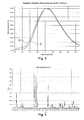
Table 4 Sr Al Ba Na SrCl2 Eu Dy RB10 RB120 Example 13 0,9260 2,050 0,0500 0,0000 0,0015 0,0125 0,010 100% 100% Example 14 0,9250 2,050 0,050 0,001 0,0015 0,0125 0,010 102% 103% Example 15 0,9245 2,050 0,0500 0,0015 0,0015 0,0125 0,010 124% 113% Example 16 0,9230 2,050 0,050 0,003 0,0015 0,0125 0,010 99% 95% Example 17 0,9160 2,050 0,0500 0,010 0,0015 0,0125 0,010 97% 94% - Table 5 shows another series of experiments, in which the effect of the magnesium content has been studied (Examples 18-22). It emerges that Example 20 shows the highest afterglow brightness and the slowest luminescence decay. The ratio between magnesium and aluminum in this phosphor is 0.0049.
Table 5 Sr Al Ba Na SrCl2 Mg Eu Dy RB10 RB120 Example 18 0,9240 2,050 0,0500 0,0020 0,0015 0,000 0,0125 0,010 100% 100% Example 19 0,9240 2,040 0,0500 0,0020 0,0015 0,0025 0,0125 0,010 115% 112% Example 20 0,9240 2,040 0,0500 0,0020 0,0015 0,010 0,0125 0,010 123% 115% Example 21 0,9240 2,025 0,0500 0,0020 0,0015 0,025 0,0125 0,010 98% 94% Example 22 0,9240 2,000 0,0500 0,0020 0,0015 0,050 0,0125 0,010 48% 50% - The influence of magnesium on the charging rate was also examined.
Figure 5 shows the charging curves 7 of Example 20 and thecharging curve 8 of Example 18. The addition of magnesium leads to a significant increase of the charging rate. - Table 6 lists Examples 23 to 26, in which manganese has been added to the luminescent materials in absence of magnesium. Example 25, which corresponds to a ratio of manganese to strontium of 0.0054, exhibits the strongest afterglow brightness.
Table 6 Sr Al Ba Mn Eu Dy RB10 RB120 Example 23 0,9275 2,050 0,0500 0,0000 0,0125 0,010 100% 100% Example 24 0,9265 2,050 0,050 0,0010 0,0125 0,010 97% 97% Example 25 0,9225 2,050 0,0500 0,005 0,0125 0,010 103% 105% Example 26 0,9175 2,050 0,0500 0,010 0,0125 0,010 101% 103% - Table 7 represents a series of experiments, in which the addition of the same amounts of manganese as in table 6 has been repeated, but with the concomitant addition of sodium (Examples 27-30). Example 29 shows the best afterglow behavior, which again corresponds to a ratio of manganese to strontium of 0.0054. Surprisingly, a synergistic effect of manganese and sodium was observed, as the influence of manganese in presence of sodium is markedly higher, in particular for the relative brightness after 120 minutes (cf. Example 29: BR120 = 113% vs. Example 25: BR120 = 105%).
Table 7 Sr Al Ba Na Mn Eu Dy RB10 RB120 Example 27 0,9255 2,050 0,0500 0,0020 0,000 0,0125 0,010 100% 100% Example 28 0,9245 2,050 0,0500 0,0020 0,0010 0,0125 0,010 104% 103% Example 29 0,9205 2,050 0,0500 0,0020 0,005 0,0125 0,010 109% 113% Example 30 0,9155 2,050 0,0500 0,0020 0,010 0,0125 0,010 107% 110% - The experiments shown in Table 8 (Examples 31-34) correspond to those of Table 6, but with lead added instead of manganese. Unlike manganese, lead had an invariably deleterious effect on the phosphorescence in this series, with a gradual decrease of the afterglow brightness through increasing lead content.
Table 8 Sr Al Ba Pb Eu Dy RB10 RB120 Example 31 0, 9275 2,050 0,0500 0,0000 0,0125 0,010 100% 100% Example 32 0, 9265 2,050 0,050 0,0010 0,0125 0,010 99% 96% Example 33 0,9225 2,050 0,0500 0,005 0,0125 0,010 94% 92% Example 34 0,9175 2,050 0,0500 0,010 0,0125 0,010 86% 84% - In Table 9 (Examples 35-38), analogous amounts of lead have been added like in table 8, but in the presence of sodium. It was observed that, in this case, the addition of lead leads to a dramatic improvement of the luminous brightness and persistence. The best result was achieved with the highest lead content, which corresponds to a ratio of lead to strontium of 0.0109 (cf. Example 38: RB10 = 130%, RB120 = 119%).
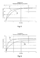
Table 9 Sr Al Ba Na Pb Eu Dy RB10 RB120 Example 35 0,9255 2,050 0,0500 0,0020 0,000 0,0125 0,010 100% 100% Example 36 0,9245 2,050 0,0500 0,0020 0,0010 0,0125 0,010 108% 107% Example 37 0,9205 2,050 0,0500 0,0020 0,005 0,0125 0,010 115% 114% Example 38 0,9155 2,050 0,0500 0,0020 0,010 0,0125 0,010 130% 119% - Tables 10 to 13 show the effect of the addition of various amounts of the main group elements Ga or Bi as well as of the transition metals Sc or Y on the phosphorescence of materials according to the present invention. It can be seen that the addition of all of those elements has an advantageous effect on brightness and length of the luminescence. In the case of the addition of Ga, the best afterglow characteristics were observed with the highest amount added (Example 42), which corresponds to a ratio of Ga to Sr of 0.0109. With the transition metals Sc and Y, best results were achieved by the addition of the same molar amount of transition metal, which corresponds to a ratio of transition metal to strontium of 0.0045 (Examples 45 and 49). For Bi, the highest increase of the relative brightness (BR10 = 115%, BR120 = 113%) was accomplished in Example 52, with a ratio of Bi to strontium of 0.0011.
Table 10 Sr Al Ba Na Ga Eu Dy RB10 RB120 Example 39 0,9255 2,050 0,0500 0,0020 0,000 0,0125 0,010 100% 100% Example 40 0,9245 2,050 0,0500 0,0020 0,0010 0,0125 0,010 100% 102% Example 41 0,9205 2,050 0,0500 0,0020 0,005 0,0125 0,010 124% 120% Example 42 0,9155 2,050 0,0500 0,0020 0,010 0,0125 0,010 124% 121% Table 11 Sr Al Ba Na Sc Eu Dy RB10 RB120 Example 43 0,9255 2,050 0,0500 0,0020 0,000 0,0125 0,010 100% 100% Example 44 0,9245 2,050 0,0500 0,0020 0,0010 0,0125 0,010 104% 105% Example 45 0,9205 2,050 0,0500 0,0020 0,005 0,0125 0,010 123% 118% Example 46 0,9155 2,050 0,0500 0,0020 0,010 0,0125 0,010 114% 107% Table 12 Sr Al Ba Na Y Eu Dy RB10 RB120 Example 47 0,9255 2,050 0,0500 0,0020 0,000 0,0125 0,010 100% 100% Example 48 0,9245 2,050 0,0500 0,0020 0,0010 0,0125 0,010 109% 105% Example 49 0,9205 2,050 0,0500 0,0020 0,005 0,0125 0,010 114% 105% Example 50 0,9155 2,050 0,0500 0,0020 0,010 0,0125 0,010 96% 89% Table 13 Sr Al Ba Na Bi Eu Dy RB10 RB120 Example 51 0,9255 2,050 0,0500 0,0020 0,000 0,0125 0,010 100% 100% Example 52 0,9245 2,050 0,0500 0,0020 0,0010 0,0125 0,010 115% 113% Example 53 0,9205 2,050 0,0500 0,0020 0,005 0,0125 0,010 88% 92% Example 54 0,9155 2,050 0,0500 0,0020 0,010 0,0125 0,010 84% 85% - The influence of the addition of scandium on the charging rates was also examined.
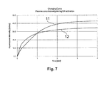
Figure 6 shows thecharging curve 9 of Example 45 and the chargingcurve 10 of Example 43. It can be seen that the addition of scandium to the materials leads to a significant increase of the charging rate. - Table 14 shows the effect of chlorine addition on the afterglow brightness. Among the materials tested, Example 56 with a ratio of chlorine to oxygen of 0.0008 showed the highest afterglow brightness and persistence (cf. Example 56: RB10 = 108%, RB120 = 112%).
Table 14 Sr Al Ba Na SrCl2 Eu Dy RB10 RB120 Example 55 0,9255 2,050 0,0500 0,0020 0,000 0,0125 0,010 100% 100% Example 56 0,9240 2,030 0,0500 0,0020 0,0015 0,0125 0,010 108% 112% Example 57 0,9225 2,030 0,0500 0,0020 0,003 0,0125 0,010 105% 110% Example 58 0,9205 2,030 0,0500 0,0020 0,005 0,0125 0,010 90% 98% Example 59 0,9155 2,030 0,0500 0,0020 0,010 0,0125 0,010 93% 100% - According to
Figure 7 , the influence of chloride addition on the charging rate was also assessed. Chargingcurve 11 corresponds to Example 55 and chargingcurve 12 to Example 56. It is evident that the addition of chloride leads to an increase of the charging rate, which is connected to a decrease of the saturation fluorescence brightness. As stated above, this property is insignificant for the afterglow properties of the materials.
Claims (15)
- A luminescent material comprising a strontium aluminate matrix, characterized in that, the material further comprises at least one alkaline earth metal, at least one alkali metal and at least one further element selected from the group consisting of- a halogen, preferably chlorine, wherein the molar ratio between the total of halogens and oxygen is between 0.00001 and 0.05, preferably between 0.00005 and 0.01, even more preferably between 0.00025 and 0.005,- magnesium, wherein the molar ratio between magnesium and aluminum is between 0.0001 and 0.03, preferably between 0.0003 and 0.02, even more preferably between 0.0005 and 0.015,- Ga, Sc, Y, Bi or any of their combinations, wherein the molar ratio between Ga, Sc, Y, Bi or any of their combinations and strontium is between 0.00001 and 0.05, preferably between 0.0001 and 0.02, even more preferably between 0.001 and 0.015,- Pb, Mn or any of their combinations, wherein the molar ratio between Pb, Mn or any of their combinations and strontium is between 0.00001 and 0.15, preferably between 0.0001 and 0.05, even more preferably between 0.001 and 0.02.
- The luminescent material according to claim 1, wherein the alkaline earth metal is selected from the group consisting of Ca and Ba, or any of their combinations.
- The luminescent material according to one of claims 1 or 2, represented by the formula:
M1 aM2 bM3 cM4 dEugM5 hSr(1-a-b-c-d-g-h)MgeAl(f-e)O(k-i)Xi
wherein
M1 = Li, Na, K, Rb, Cs or any of their combinations;
a = 0.00001 to 0.02, preferably 0.0001 to 0.015, even more preferably 0.00025 to 0.01;
M2 = Ba, Ca or any of their combinations;
b = 0.00002 to 0.15, preferably 0.001 to 0.1, even more preferably 0.0025 to 0.075;
M3 = Sc, Ga, Y, Bi or any of their combinations;
c = 0 or
c = 0.00001 to 0.05, preferably 0.0001 to 0.03, even more preferably 0.001 to 0.02;
M4 = Mn, Pb or any of their combinations;
d = 0 or
d = 0.00001 to 0.15, preferably 0.0001 to 0.05, even more preferably 0.001 to 0.02;
e = 0 or
e = 0.0002 to 0.06, preferably 0.0006 to 0.04, even more preferably 0.001 to 0.03;
f = 1.8 to 2.6;
g = 0.00001 to 0.06;
M5 = Dy, Nd or any of their combinations;
h = 0 or
h = 0.00001 to 0.06;
X = F, Cl, Br, I, At or any of their combinations;
i = 0 or
i = 0.00004 to 0.2, preferably 0.0002 to 0.04, even more preferably 0.001 to 0.002. - A luminescent material according to one of claims 1 to 3, having a particle size distribution, wherein at least 60% of the particles have a diameter between 1 µm and 200 µm, preferably between 2 µm and 100 µm, even more preferably between 5 µm and 60 µm.
- A luminescent material according to one of claims 1 to 3, having a particle size distribution, wherein at least 90% of the particles have a diameter between 1 µm and 200 µm, preferably between 2 µm and 100 µm, even more preferably between 5 µm and 60 µm.
- A luminescent material according to one of claims 1 to 5, having an emission wavelength between 420 nm and 700 nm.
- A luminescent material according to one of claims 1 to 6, having an emission maximum between 480 nm and 550 nm.
- A method for preparing a luminescent material, comprising the steps of- mixing the starting materials to obtain a mixture, preferably in the solid state, even more preferably with a ball mill,- heating the mixture under reductive conditions, in particular under a reductive atmosphere, preferably comprising N2/H2 or N2/CO, wherein the mixture is heated to a temperature between 1000 °C and 2000 °C, preferably between 1100 °C and 1900 °C, even more preferably between 1300 °C and 1700 °C,- allowing the mixture to cool to ambient temperature,- milling the resulting product to obtain a milled product,
characterized in that, the composition of the chemical elements in the mixture satisfies the formula
M1 aM2 bM3 cM4 dEu(g-h)M5 hSr(1-a-b-c-d-g)MgeAl(f-e)O(k-i)Xi
wherein
M1 = Li, Na, K, Rb, Cs or any of their combinations;
a = 0.00001 to 0.02, preferably 0.0001 to 0.015, even more preferably 0.00025 to 0.01;
M2 = Ba, Ca or any of their combinations;
b = 0.00002 to 0.15, preferably 0.001 to 0.1, even more preferably 0.0025 to 0.075;
M3 = Sc, Ga, Y, Bi or any of their combinations;
c = 0 or
c = 0.00001 to 0.05, preferably 0.0001 to 0.03, even more preferably 0.001 to 0.02;
M4 = Mn, Pb or any of their combinations;
d = 0 or
d = 0.00001 to 0.15, preferably 0.0001 to 0.05, even more preferably 0.001 to 0.02;
e = 0 or
e = 0.0002 to 0.06, preferably 0.0006 to 0.04, even more preferably 0.001 to 0.03;
f = 1.8 to 2.6;
g = 0.00001 to 0.06;
M5 = Dy, Nd or any of their combinations;
h = 0 or
h = 0.00001 to 0.06;
X = F, Cl, Br, I, At or any of their combinations;
i = 0 or
i = 0.00004 to 0.2, preferably 0.0002 to 0.04, even more preferably 0.001 to 0.002. - A method for preparing a luminescent material according to claim 8, characterized in that, the starting materials are metal oxides and/or metal carbonates and/or metal halogens, in particular metal chlorides.
- A method for preparing a luminescent material according to one of claims 8 or 9, characterized in that at least one starting material is a metal salt that undergoes conversion to the corresponding oxide upon heating of the mixture under the conditions set forth in claim 8, wherein the metal salt preferably is a carboxylate, even more preferably an acetate or an oxalate.
- A method for preparing a luminescent material according to one of claims 8 to 10, additionally comprising the step of fractionizing the milled product according to the particle size.
- A method for preparing a luminescent material according to one of claims 8 to 11, characterized in that, the mixture of starting materials additionally contains a fluxing agent, preferably boric acid or boron trioxide, wherein the portion of the fluxing agent in the mixture is not considered in the composition of the chemical elements.
- Formulation containing a luminescent material according to one of claims 1 to 7.
- Use of a luminescent material according to one of claims 1 to 7, or of a formulation according to claim 12, for at least partially coating an object.
- Object at least partially coated with a luminescent material according to one of claims 1 to 7, or with a formulation according to claim 12.
Priority Applications (3)
| Application Number | Priority Date | Filing Date | Title |
|---|---|---|---|
| PT151644978T PT3085752T (en) | 2015-04-21 | 2015-04-21 | Luminescent material |
| EP15164497.8A EP3085752B1 (en) | 2015-04-21 | 2015-04-21 | Luminescent material comprising a strontium aluminate matrix |
| PCT/EP2016/055415 WO2016169700A1 (en) | 2015-04-21 | 2016-03-14 | Luminescent material |
Applications Claiming Priority (1)
| Application Number | Priority Date | Filing Date | Title |
|---|---|---|---|
| EP15164497.8A EP3085752B1 (en) | 2015-04-21 | 2015-04-21 | Luminescent material comprising a strontium aluminate matrix |
Publications (2)
| Publication Number | Publication Date |
|---|---|
| EP3085752A1 true EP3085752A1 (en) | 2016-10-26 |
| EP3085752B1 EP3085752B1 (en) | 2020-01-15 |
Family
ID=52997331
Family Applications (1)
| Application Number | Title | Priority Date | Filing Date |
|---|---|---|---|
| EP15164497.8A Active EP3085752B1 (en) | 2015-04-21 | 2015-04-21 | Luminescent material comprising a strontium aluminate matrix |
Country Status (3)
| Country | Link |
|---|---|
| EP (1) | EP3085752B1 (en) |
| PT (1) | PT3085752T (en) |
| WO (1) | WO2016169700A1 (en) |
Cited By (1)
| Publication number | Priority date | Publication date | Assignee | Title |
|---|---|---|---|---|
| CN110534328A (en) * | 2019-09-02 | 2019-12-03 | 北京工业大学 | A kind of method that liquid nitrogen cryogenics ball milling prepares high-coercive force manganese gallium magnetic powder |
Citations (6)
| Publication number | Priority date | Publication date | Assignee | Title |
|---|---|---|---|---|
| US5424006A (en) * | 1993-04-28 | 1995-06-13 | Nemoto & Co., Ltd. | Phosphorescent phosphor |
| US5686022A (en) * | 1994-11-01 | 1997-11-11 | Nemoto & Co., Ltd. | Phosphorescent phosphor |
| US20080277624A1 (en) * | 2005-10-28 | 2008-11-13 | Beladakere Nagendra N | Photoluminescent Material |
| US20100176342A1 (en) * | 2004-06-10 | 2010-07-15 | Seoul Semiconductor Co., Ltd. | Luminescent material |
| WO2011008930A2 (en) | 2009-07-15 | 2011-01-20 | Performance Indicator Llc | Phosphorescent phosphors |
| EP2626401A1 (en) * | 2012-02-10 | 2013-08-14 | Rolex Sa | Novel long decay phosphors |
-
2015
- 2015-04-21 EP EP15164497.8A patent/EP3085752B1/en active Active
- 2015-04-21 PT PT151644978T patent/PT3085752T/en unknown
-
2016
- 2016-03-14 WO PCT/EP2016/055415 patent/WO2016169700A1/en active Application Filing
Patent Citations (7)
| Publication number | Priority date | Publication date | Assignee | Title |
|---|---|---|---|---|
| US5424006A (en) * | 1993-04-28 | 1995-06-13 | Nemoto & Co., Ltd. | Phosphorescent phosphor |
| US5686022A (en) * | 1994-11-01 | 1997-11-11 | Nemoto & Co., Ltd. | Phosphorescent phosphor |
| US20100176342A1 (en) * | 2004-06-10 | 2010-07-15 | Seoul Semiconductor Co., Ltd. | Luminescent material |
| US20080277624A1 (en) * | 2005-10-28 | 2008-11-13 | Beladakere Nagendra N | Photoluminescent Material |
| WO2011008930A2 (en) | 2009-07-15 | 2011-01-20 | Performance Indicator Llc | Phosphorescent phosphors |
| US20110012059A1 (en) * | 2009-07-15 | 2011-01-20 | Weiyi Jia | Novel phosphorescent phosphors |
| EP2626401A1 (en) * | 2012-02-10 | 2013-08-14 | Rolex Sa | Novel long decay phosphors |
Non-Patent Citations (1)
| Title |
|---|
| J. ELEC-TROCHEM. SOC., vol. 143, 1996, pages 2670 - 2673 |
Cited By (1)
| Publication number | Priority date | Publication date | Assignee | Title |
|---|---|---|---|---|
| CN110534328A (en) * | 2019-09-02 | 2019-12-03 | 北京工业大学 | A kind of method that liquid nitrogen cryogenics ball milling prepares high-coercive force manganese gallium magnetic powder |
Also Published As
| Publication number | Publication date |
|---|---|
| EP3085752B1 (en) | 2020-01-15 |
| WO2016169700A1 (en) | 2016-10-27 |
| PT3085752T (en) | 2020-03-02 |
Similar Documents
| Publication | Publication Date | Title |
|---|---|---|
| US8329061B2 (en) | Phosphorescent phosphors | |
| EP2596079B1 (en) | Blend comprising an oxynitride phosphor and light emitting apparatus using it | |
| WO2015099145A1 (en) | Phosphor and method for producing phosphor | |
| EP2540797B1 (en) | Phosphorescent phosphor and phosphorescent pigment | |
| US10125315B2 (en) | Phosphors and phosphor-converted LEDs | |
| EP2626401A1 (en) | Novel long decay phosphors | |
| WO2017092849A1 (en) | Mn-activated phosphors | |
| JP5039706B2 (en) | Long afterglow luminescent material and method for producing the same | |
| JP4628957B2 (en) | Luminescent phosphor and method for producing the same | |
| DE102009030205A1 (en) | Luminescent substance with europium-doped silicate luminophore, useful in LED, comprises alkaline-, rare-earth metal orthosilicate, and solid solution in form of mixed phases arranged between alkaline- and rare-earth metal oxyorthosilicate | |
| JP2015131946A (en) | phosphor | |
| EP3088488B1 (en) | Phosphorescent phosphor | |
| EP3085752B1 (en) | Luminescent material comprising a strontium aluminate matrix | |
| JP4956732B2 (en) | Phosphors and color display devices for electron beam excitation | |
| JP3559210B2 (en) | Heat-resistant, water-resistant, high-brightness, long-lasting yellow-green luminescent color phosphor and a method for producing the same | |
| JP3268761B2 (en) | High brightness and long afterglow aluminate phosphor with excellent heat and weather resistance | |
| US20090173915A1 (en) | Light-storing phosphor | |
| US20120097896A1 (en) | Blue-green silicate luminescent material | |
| JP2000034480A (en) | Phosphorescent phosphor | |
| JP5774297B2 (en) | Luminescent phosphor and method for producing the same | |
| JP3585994B2 (en) | Method for producing alkaline earth metal aluminate phosphorescent phosphor | |
| JP2005232414A (en) | Strontium aluminate-based luminous powder and its production method | |
| JP6741614B2 (en) | Rare earth activated alkaline earth silicate compound Afterglow phosphor | |
| KR20160111463A (en) | Fluorescent material and light-emitting device | |
| JP2017155215A (en) | Halo phosphate fluophor and manufacturing method therefor |
Legal Events
| Date | Code | Title | Description |
|---|---|---|---|
| PUAI | Public reference made under article 153(3) epc to a published international application that has entered the european phase |
Free format text: ORIGINAL CODE: 0009012 |
|
| AK | Designated contracting states |
Kind code of ref document: A1 Designated state(s): AL AT BE BG CH CY CZ DE DK EE ES FI FR GB GR HR HU IE IS IT LI LT LU LV MC MK MT NL NO PL PT RO RS SE SI SK SM TR |
|
| AX | Request for extension of the european patent |
Extension state: BA ME |
|
| STAA | Information on the status of an ep patent application or granted ep patent |
Free format text: STATUS: REQUEST FOR EXAMINATION WAS MADE |
|
| 17P | Request for examination filed |
Effective date: 20170406 |
|
| RBV | Designated contracting states (corrected) |
Designated state(s): AL AT BE BG CH CY CZ DE DK EE ES FI FR GB GR HR HU IE IS IT LI LT LU LV MC MK MT NL NO PL PT RO RS SE SI SK SM TR |
|
| STAA | Information on the status of an ep patent application or granted ep patent |
Free format text: STATUS: EXAMINATION IS IN PROGRESS |
|
| 17Q | First examination report despatched |
Effective date: 20180214 |
|
| GRAP | Despatch of communication of intention to grant a patent |
Free format text: ORIGINAL CODE: EPIDOSNIGR1 |
|
| STAA | Information on the status of an ep patent application or granted ep patent |
Free format text: STATUS: GRANT OF PATENT IS INTENDED |
|
| INTG | Intention to grant announced |
Effective date: 20190902 |
|
| GRAS | Grant fee paid |
Free format text: ORIGINAL CODE: EPIDOSNIGR3 |
|
| GRAA | (expected) grant |
Free format text: ORIGINAL CODE: 0009210 |
|
| STAA | Information on the status of an ep patent application or granted ep patent |
Free format text: STATUS: THE PATENT HAS BEEN GRANTED |
|
| AK | Designated contracting states |
Kind code of ref document: B1 Designated state(s): AL AT BE BG CH CY CZ DE DK EE ES FI FR GB GR HR HU IE IS IT LI LT LU LV MC MK MT NL NO PL PT RO RS SE SI SK SM TR |
|
| REG | Reference to a national code |
Ref country code: CH Ref legal event code: EP Ref country code: GB Ref legal event code: FG4D |
|
| REG | Reference to a national code |
Ref country code: CH Ref legal event code: NV Representative=s name: HEPP WENGER RYFFEL AG, CH |
|
| REG | Reference to a national code |
Ref country code: IE Ref legal event code: FG4D |
|
| REG | Reference to a national code |
Ref country code: DE Ref legal event code: R096 Ref document number: 602015045483 Country of ref document: DE |
|
| REG | Reference to a national code |
Ref country code: AT Ref legal event code: REF Ref document number: 1225140 Country of ref document: AT Kind code of ref document: T Effective date: 20200215 |
|
| REG | Reference to a national code |
Ref country code: PT Ref legal event code: SC4A Ref document number: 3085752 Country of ref document: PT Date of ref document: 20200302 Kind code of ref document: T Free format text: AVAILABILITY OF NATIONAL TRANSLATION Effective date: 20200219 |
|
| REG | Reference to a national code |
Ref country code: NL Ref legal event code: MP Effective date: 20200115 |
|
| REG | Reference to a national code |
Ref country code: LT Ref legal event code: MG4D |
|
| PG25 | Lapsed in a contracting state [announced via postgrant information from national office to epo] |
Ref country code: FI Free format text: LAPSE BECAUSE OF FAILURE TO SUBMIT A TRANSLATION OF THE DESCRIPTION OR TO PAY THE FEE WITHIN THE PRESCRIBED TIME-LIMIT Effective date: 20200115 Ref country code: NO Free format text: LAPSE BECAUSE OF FAILURE TO SUBMIT A TRANSLATION OF THE DESCRIPTION OR TO PAY THE FEE WITHIN THE PRESCRIBED TIME-LIMIT Effective date: 20200415 Ref country code: RS Free format text: LAPSE BECAUSE OF FAILURE TO SUBMIT A TRANSLATION OF THE DESCRIPTION OR TO PAY THE FEE WITHIN THE PRESCRIBED TIME-LIMIT Effective date: 20200115 Ref country code: NL Free format text: LAPSE BECAUSE OF FAILURE TO SUBMIT A TRANSLATION OF THE DESCRIPTION OR TO PAY THE FEE WITHIN THE PRESCRIBED TIME-LIMIT Effective date: 20200115 |
|
| PG25 | Lapsed in a contracting state [announced via postgrant information from national office to epo] |
Ref country code: GR Free format text: LAPSE BECAUSE OF FAILURE TO SUBMIT A TRANSLATION OF THE DESCRIPTION OR TO PAY THE FEE WITHIN THE PRESCRIBED TIME-LIMIT Effective date: 20200416 Ref country code: BG Free format text: LAPSE BECAUSE OF FAILURE TO SUBMIT A TRANSLATION OF THE DESCRIPTION OR TO PAY THE FEE WITHIN THE PRESCRIBED TIME-LIMIT Effective date: 20200415 Ref country code: IS Free format text: LAPSE BECAUSE OF FAILURE TO SUBMIT A TRANSLATION OF THE DESCRIPTION OR TO PAY THE FEE WITHIN THE PRESCRIBED TIME-LIMIT Effective date: 20200515 Ref country code: SE Free format text: LAPSE BECAUSE OF FAILURE TO SUBMIT A TRANSLATION OF THE DESCRIPTION OR TO PAY THE FEE WITHIN THE PRESCRIBED TIME-LIMIT Effective date: 20200115 Ref country code: HR Free format text: LAPSE BECAUSE OF FAILURE TO SUBMIT A TRANSLATION OF THE DESCRIPTION OR TO PAY THE FEE WITHIN THE PRESCRIBED TIME-LIMIT Effective date: 20200115 Ref country code: LV Free format text: LAPSE BECAUSE OF FAILURE TO SUBMIT A TRANSLATION OF THE DESCRIPTION OR TO PAY THE FEE WITHIN THE PRESCRIBED TIME-LIMIT Effective date: 20200115 |
|
| REG | Reference to a national code |
Ref country code: DE Ref legal event code: R097 Ref document number: 602015045483 Country of ref document: DE |
|
| PG25 | Lapsed in a contracting state [announced via postgrant information from national office to epo] |
Ref country code: CZ Free format text: LAPSE BECAUSE OF FAILURE TO SUBMIT A TRANSLATION OF THE DESCRIPTION OR TO PAY THE FEE WITHIN THE PRESCRIBED TIME-LIMIT Effective date: 20200115 Ref country code: RO Free format text: LAPSE BECAUSE OF FAILURE TO SUBMIT A TRANSLATION OF THE DESCRIPTION OR TO PAY THE FEE WITHIN THE PRESCRIBED TIME-LIMIT Effective date: 20200115 Ref country code: ES Free format text: LAPSE BECAUSE OF FAILURE TO SUBMIT A TRANSLATION OF THE DESCRIPTION OR TO PAY THE FEE WITHIN THE PRESCRIBED TIME-LIMIT Effective date: 20200115 Ref country code: SM Free format text: LAPSE BECAUSE OF FAILURE TO SUBMIT A TRANSLATION OF THE DESCRIPTION OR TO PAY THE FEE WITHIN THE PRESCRIBED TIME-LIMIT Effective date: 20200115 Ref country code: LT Free format text: LAPSE BECAUSE OF FAILURE TO SUBMIT A TRANSLATION OF THE DESCRIPTION OR TO PAY THE FEE WITHIN THE PRESCRIBED TIME-LIMIT Effective date: 20200115 Ref country code: EE Free format text: LAPSE BECAUSE OF FAILURE TO SUBMIT A TRANSLATION OF THE DESCRIPTION OR TO PAY THE FEE WITHIN THE PRESCRIBED TIME-LIMIT Effective date: 20200115 Ref country code: SK Free format text: LAPSE BECAUSE OF FAILURE TO SUBMIT A TRANSLATION OF THE DESCRIPTION OR TO PAY THE FEE WITHIN THE PRESCRIBED TIME-LIMIT Effective date: 20200115 Ref country code: DK Free format text: LAPSE BECAUSE OF FAILURE TO SUBMIT A TRANSLATION OF THE DESCRIPTION OR TO PAY THE FEE WITHIN THE PRESCRIBED TIME-LIMIT Effective date: 20200115 |
|
| PLBE | No opposition filed within time limit |
Free format text: ORIGINAL CODE: 0009261 |
|
| STAA | Information on the status of an ep patent application or granted ep patent |
Free format text: STATUS: NO OPPOSITION FILED WITHIN TIME LIMIT |
|
| PG25 | Lapsed in a contracting state [announced via postgrant information from national office to epo] |
Ref country code: MC Free format text: LAPSE BECAUSE OF FAILURE TO SUBMIT A TRANSLATION OF THE DESCRIPTION OR TO PAY THE FEE WITHIN THE PRESCRIBED TIME-LIMIT Effective date: 20200115 |
|
| 26N | No opposition filed |
Effective date: 20201016 |
|
| PG25 | Lapsed in a contracting state [announced via postgrant information from national office to epo] |
Ref country code: LU Free format text: LAPSE BECAUSE OF NON-PAYMENT OF DUE FEES Effective date: 20200421 Ref country code: IT Free format text: LAPSE BECAUSE OF FAILURE TO SUBMIT A TRANSLATION OF THE DESCRIPTION OR TO PAY THE FEE WITHIN THE PRESCRIBED TIME-LIMIT Effective date: 20200115 |
|
| REG | Reference to a national code |
Ref country code: BE Ref legal event code: MM Effective date: 20200430 |
|
| PG25 | Lapsed in a contracting state [announced via postgrant information from national office to epo] |
Ref country code: PL Free format text: LAPSE BECAUSE OF FAILURE TO SUBMIT A TRANSLATION OF THE DESCRIPTION OR TO PAY THE FEE WITHIN THE PRESCRIBED TIME-LIMIT Effective date: 20200115 Ref country code: BE Free format text: LAPSE BECAUSE OF NON-PAYMENT OF DUE FEES Effective date: 20200430 Ref country code: SI Free format text: LAPSE BECAUSE OF FAILURE TO SUBMIT A TRANSLATION OF THE DESCRIPTION OR TO PAY THE FEE WITHIN THE PRESCRIBED TIME-LIMIT Effective date: 20200115 |
|
| REG | Reference to a national code |
Ref country code: AT Ref legal event code: UEP Ref document number: 1225140 Country of ref document: AT Kind code of ref document: T Effective date: 20200115 |
|
| PG25 | Lapsed in a contracting state [announced via postgrant information from national office to epo] |
Ref country code: IE Free format text: LAPSE BECAUSE OF NON-PAYMENT OF DUE FEES Effective date: 20200421 |
|
| PG25 | Lapsed in a contracting state [announced via postgrant information from national office to epo] |
Ref country code: TR Free format text: LAPSE BECAUSE OF FAILURE TO SUBMIT A TRANSLATION OF THE DESCRIPTION OR TO PAY THE FEE WITHIN THE PRESCRIBED TIME-LIMIT Effective date: 20200115 Ref country code: MT Free format text: LAPSE BECAUSE OF FAILURE TO SUBMIT A TRANSLATION OF THE DESCRIPTION OR TO PAY THE FEE WITHIN THE PRESCRIBED TIME-LIMIT Effective date: 20200115 Ref country code: CY Free format text: LAPSE BECAUSE OF FAILURE TO SUBMIT A TRANSLATION OF THE DESCRIPTION OR TO PAY THE FEE WITHIN THE PRESCRIBED TIME-LIMIT Effective date: 20200115 |
|
| PG25 | Lapsed in a contracting state [announced via postgrant information from national office to epo] |
Ref country code: MK Free format text: LAPSE BECAUSE OF FAILURE TO SUBMIT A TRANSLATION OF THE DESCRIPTION OR TO PAY THE FEE WITHIN THE PRESCRIBED TIME-LIMIT Effective date: 20200115 Ref country code: AL Free format text: LAPSE BECAUSE OF FAILURE TO SUBMIT A TRANSLATION OF THE DESCRIPTION OR TO PAY THE FEE WITHIN THE PRESCRIBED TIME-LIMIT Effective date: 20200115 |
|
| PGFP | Annual fee paid to national office [announced via postgrant information from national office to epo] |
Ref country code: FR Payment date: 20230309 Year of fee payment: 9 |
|
| PGFP | Annual fee paid to national office [announced via postgrant information from national office to epo] |
Ref country code: GB Payment date: 20230302 Year of fee payment: 9 |
|
| PGFP | Annual fee paid to national office [announced via postgrant information from national office to epo] |
Ref country code: PT Payment date: 20230419 Year of fee payment: 9 Ref country code: DE Payment date: 20230307 Year of fee payment: 9 Ref country code: CH Payment date: 20230622 Year of fee payment: 9 |
|
| PGFP | Annual fee paid to national office [announced via postgrant information from national office to epo] |
Ref country code: AT Payment date: 20230327 Year of fee payment: 9 |