EP3085677A1 - Piezoelectric ceramic plate, plate-shaped substrate and electronic component - Google Patents
Piezoelectric ceramic plate, plate-shaped substrate and electronic component Download PDFInfo
- Publication number
- EP3085677A1 EP3085677A1 EP15835045.4A EP15835045A EP3085677A1 EP 3085677 A1 EP3085677 A1 EP 3085677A1 EP 15835045 A EP15835045 A EP 15835045A EP 3085677 A1 EP3085677 A1 EP 3085677A1
- Authority
- EP
- European Patent Office
- Prior art keywords
- piezoelectric ceramic
- ceramic plate
- pair
- side surfaces
- piezoelectric
- Prior art date
- Legal status (The legal status is an assumption and is not a legal conclusion. Google has not performed a legal analysis and makes no representation as to the accuracy of the status listed.)
- Granted
Links
Images



Classifications
-
- H—ELECTRICITY
- H10—SEMICONDUCTOR DEVICES; ELECTRIC SOLID-STATE DEVICES NOT OTHERWISE PROVIDED FOR
- H10N—ELECTRIC SOLID-STATE DEVICES NOT OTHERWISE PROVIDED FOR
- H10N30/00—Piezoelectric or electrostrictive devices
- H10N30/80—Constructional details
- H10N30/85—Piezoelectric or electrostrictive active materials
- H10N30/853—Ceramic compositions
- H10N30/8548—Lead-based oxides
- H10N30/8554—Lead-zirconium titanate [PZT] based
-
- C—CHEMISTRY; METALLURGY
- C04—CEMENTS; CONCRETE; ARTIFICIAL STONE; CERAMICS; REFRACTORIES
- C04B—LIME, MAGNESIA; SLAG; CEMENTS; COMPOSITIONS THEREOF, e.g. MORTARS, CONCRETE OR LIKE BUILDING MATERIALS; ARTIFICIAL STONE; CERAMICS; REFRACTORIES; TREATMENT OF NATURAL STONE
- C04B35/00—Shaped ceramic products characterised by their composition; Ceramics compositions; Processing powders of inorganic compounds preparatory to the manufacturing of ceramic products
- C04B35/01—Shaped ceramic products characterised by their composition; Ceramics compositions; Processing powders of inorganic compounds preparatory to the manufacturing of ceramic products based on oxide ceramics
- C04B35/48—Shaped ceramic products characterised by their composition; Ceramics compositions; Processing powders of inorganic compounds preparatory to the manufacturing of ceramic products based on oxide ceramics based on zirconium or hafnium oxides, zirconates, zircon or hafnates
- C04B35/49—Shaped ceramic products characterised by their composition; Ceramics compositions; Processing powders of inorganic compounds preparatory to the manufacturing of ceramic products based on oxide ceramics based on zirconium or hafnium oxides, zirconates, zircon or hafnates containing also titanium oxides or titanates
- C04B35/491—Shaped ceramic products characterised by their composition; Ceramics compositions; Processing powders of inorganic compounds preparatory to the manufacturing of ceramic products based on oxide ceramics based on zirconium or hafnium oxides, zirconates, zircon or hafnates containing also titanium oxides or titanates based on lead zirconates and lead titanates, e.g. PZT
- C04B35/493—Shaped ceramic products characterised by their composition; Ceramics compositions; Processing powders of inorganic compounds preparatory to the manufacturing of ceramic products based on oxide ceramics based on zirconium or hafnium oxides, zirconates, zircon or hafnates containing also titanium oxides or titanates based on lead zirconates and lead titanates, e.g. PZT containing also other lead compounds
-
- C—CHEMISTRY; METALLURGY
- C04—CEMENTS; CONCRETE; ARTIFICIAL STONE; CERAMICS; REFRACTORIES
- C04B—LIME, MAGNESIA; SLAG; CEMENTS; COMPOSITIONS THEREOF, e.g. MORTARS, CONCRETE OR LIKE BUILDING MATERIALS; ARTIFICIAL STONE; CERAMICS; REFRACTORIES; TREATMENT OF NATURAL STONE
- C04B35/00—Shaped ceramic products characterised by their composition; Ceramics compositions; Processing powders of inorganic compounds preparatory to the manufacturing of ceramic products
- C04B35/622—Forming processes; Processing powders of inorganic compounds preparatory to the manufacturing of ceramic products
- C04B35/626—Preparing or treating the powders individually or as batches ; preparing or treating macroscopic reinforcing agents for ceramic products, e.g. fibres; mechanical aspects section B
- C04B35/62605—Treating the starting powders individually or as mixtures
- C04B35/62645—Thermal treatment of powders or mixtures thereof other than sintering
-
- H—ELECTRICITY
- H10—SEMICONDUCTOR DEVICES; ELECTRIC SOLID-STATE DEVICES NOT OTHERWISE PROVIDED FOR
- H10N—ELECTRIC SOLID-STATE DEVICES NOT OTHERWISE PROVIDED FOR
- H10N30/00—Piezoelectric or electrostrictive devices
- H10N30/01—Manufacture or treatment
- H10N30/05—Manufacture of multilayered piezoelectric or electrostrictive devices, or parts thereof, e.g. by stacking piezoelectric bodies and electrodes
- H10N30/057—Manufacture of multilayered piezoelectric or electrostrictive devices, or parts thereof, e.g. by stacking piezoelectric bodies and electrodes by stacking bulk piezoelectric or electrostrictive bodies and electrodes
-
- H—ELECTRICITY
- H10—SEMICONDUCTOR DEVICES; ELECTRIC SOLID-STATE DEVICES NOT OTHERWISE PROVIDED FOR
- H10N—ELECTRIC SOLID-STATE DEVICES NOT OTHERWISE PROVIDED FOR
- H10N30/00—Piezoelectric or electrostrictive devices
- H10N30/01—Manufacture or treatment
- H10N30/06—Forming electrodes or interconnections, e.g. leads or terminals
- H10N30/067—Forming single-layered electrodes of multilayered piezoelectric or electrostrictive parts
-
- H—ELECTRICITY
- H10—SEMICONDUCTOR DEVICES; ELECTRIC SOLID-STATE DEVICES NOT OTHERWISE PROVIDED FOR
- H10N—ELECTRIC SOLID-STATE DEVICES NOT OTHERWISE PROVIDED FOR
- H10N30/00—Piezoelectric or electrostrictive devices
- H10N30/01—Manufacture or treatment
- H10N30/09—Forming piezoelectric or electrostrictive materials
- H10N30/093—Forming inorganic materials
- H10N30/097—Forming inorganic materials by sintering
-
- H—ELECTRICITY
- H10—SEMICONDUCTOR DEVICES; ELECTRIC SOLID-STATE DEVICES NOT OTHERWISE PROVIDED FOR
- H10N—ELECTRIC SOLID-STATE DEVICES NOT OTHERWISE PROVIDED FOR
- H10N30/00—Piezoelectric or electrostrictive devices
- H10N30/80—Constructional details
- H10N30/87—Electrodes or interconnections, e.g. leads or terminals
- H10N30/871—Single-layered electrodes of multilayer piezoelectric or electrostrictive devices, e.g. internal electrodes
-
- H—ELECTRICITY
- H10—SEMICONDUCTOR DEVICES; ELECTRIC SOLID-STATE DEVICES NOT OTHERWISE PROVIDED FOR
- H10N—ELECTRIC SOLID-STATE DEVICES NOT OTHERWISE PROVIDED FOR
- H10N30/00—Piezoelectric or electrostrictive devices
- H10N30/80—Constructional details
- H10N30/87—Electrodes or interconnections, e.g. leads or terminals
- H10N30/875—Further connection or lead arrangements, e.g. flexible wiring boards, terminal pins
-
- C—CHEMISTRY; METALLURGY
- C04—CEMENTS; CONCRETE; ARTIFICIAL STONE; CERAMICS; REFRACTORIES
- C04B—LIME, MAGNESIA; SLAG; CEMENTS; COMPOSITIONS THEREOF, e.g. MORTARS, CONCRETE OR LIKE BUILDING MATERIALS; ARTIFICIAL STONE; CERAMICS; REFRACTORIES; TREATMENT OF NATURAL STONE
- C04B2235/00—Aspects relating to ceramic starting mixtures or sintered ceramic products
- C04B2235/02—Composition of constituents of the starting material or of secondary phases of the final product
- C04B2235/30—Constituents and secondary phases not being of a fibrous nature
- C04B2235/32—Metal oxides, mixed metal oxides, or oxide-forming salts thereof, e.g. carbonates, nitrates, (oxy)hydroxides, chlorides
- C04B2235/3201—Alkali metal oxides or oxide-forming salts thereof
- C04B2235/3203—Lithium oxide or oxide-forming salts thereof
-
- C—CHEMISTRY; METALLURGY
- C04—CEMENTS; CONCRETE; ARTIFICIAL STONE; CERAMICS; REFRACTORIES
- C04B—LIME, MAGNESIA; SLAG; CEMENTS; COMPOSITIONS THEREOF, e.g. MORTARS, CONCRETE OR LIKE BUILDING MATERIALS; ARTIFICIAL STONE; CERAMICS; REFRACTORIES; TREATMENT OF NATURAL STONE
- C04B2235/00—Aspects relating to ceramic starting mixtures or sintered ceramic products
- C04B2235/02—Composition of constituents of the starting material or of secondary phases of the final product
- C04B2235/30—Constituents and secondary phases not being of a fibrous nature
- C04B2235/32—Metal oxides, mixed metal oxides, or oxide-forming salts thereof, e.g. carbonates, nitrates, (oxy)hydroxides, chlorides
- C04B2235/3205—Alkaline earth oxides or oxide forming salts thereof, e.g. beryllium oxide
- C04B2235/3213—Strontium oxides or oxide-forming salts thereof
-
- C—CHEMISTRY; METALLURGY
- C04—CEMENTS; CONCRETE; ARTIFICIAL STONE; CERAMICS; REFRACTORIES
- C04B—LIME, MAGNESIA; SLAG; CEMENTS; COMPOSITIONS THEREOF, e.g. MORTARS, CONCRETE OR LIKE BUILDING MATERIALS; ARTIFICIAL STONE; CERAMICS; REFRACTORIES; TREATMENT OF NATURAL STONE
- C04B2235/00—Aspects relating to ceramic starting mixtures or sintered ceramic products
- C04B2235/02—Composition of constituents of the starting material or of secondary phases of the final product
- C04B2235/30—Constituents and secondary phases not being of a fibrous nature
- C04B2235/32—Metal oxides, mixed metal oxides, or oxide-forming salts thereof, e.g. carbonates, nitrates, (oxy)hydroxides, chlorides
- C04B2235/3205—Alkaline earth oxides or oxide forming salts thereof, e.g. beryllium oxide
- C04B2235/3215—Barium oxides or oxide-forming salts thereof
-
- C—CHEMISTRY; METALLURGY
- C04—CEMENTS; CONCRETE; ARTIFICIAL STONE; CERAMICS; REFRACTORIES
- C04B—LIME, MAGNESIA; SLAG; CEMENTS; COMPOSITIONS THEREOF, e.g. MORTARS, CONCRETE OR LIKE BUILDING MATERIALS; ARTIFICIAL STONE; CERAMICS; REFRACTORIES; TREATMENT OF NATURAL STONE
- C04B2235/00—Aspects relating to ceramic starting mixtures or sintered ceramic products
- C04B2235/02—Composition of constituents of the starting material or of secondary phases of the final product
- C04B2235/30—Constituents and secondary phases not being of a fibrous nature
- C04B2235/32—Metal oxides, mixed metal oxides, or oxide-forming salts thereof, e.g. carbonates, nitrates, (oxy)hydroxides, chlorides
- C04B2235/3231—Refractory metal oxides, their mixed metal oxides, or oxide-forming salts thereof
- C04B2235/3251—Niobium oxides, niobates, tantalum oxides, tantalates, or oxide-forming salts thereof
-
- C—CHEMISTRY; METALLURGY
- C04—CEMENTS; CONCRETE; ARTIFICIAL STONE; CERAMICS; REFRACTORIES
- C04B—LIME, MAGNESIA; SLAG; CEMENTS; COMPOSITIONS THEREOF, e.g. MORTARS, CONCRETE OR LIKE BUILDING MATERIALS; ARTIFICIAL STONE; CERAMICS; REFRACTORIES; TREATMENT OF NATURAL STONE
- C04B2235/00—Aspects relating to ceramic starting mixtures or sintered ceramic products
- C04B2235/02—Composition of constituents of the starting material or of secondary phases of the final product
- C04B2235/30—Constituents and secondary phases not being of a fibrous nature
- C04B2235/32—Metal oxides, mixed metal oxides, or oxide-forming salts thereof, e.g. carbonates, nitrates, (oxy)hydroxides, chlorides
- C04B2235/327—Iron group oxides, their mixed metal oxides, or oxide-forming salts thereof
- C04B2235/3279—Nickel oxides, nickalates, or oxide-forming salts thereof
-
- C—CHEMISTRY; METALLURGY
- C04—CEMENTS; CONCRETE; ARTIFICIAL STONE; CERAMICS; REFRACTORIES
- C04B—LIME, MAGNESIA; SLAG; CEMENTS; COMPOSITIONS THEREOF, e.g. MORTARS, CONCRETE OR LIKE BUILDING MATERIALS; ARTIFICIAL STONE; CERAMICS; REFRACTORIES; TREATMENT OF NATURAL STONE
- C04B2235/00—Aspects relating to ceramic starting mixtures or sintered ceramic products
- C04B2235/02—Composition of constituents of the starting material or of secondary phases of the final product
- C04B2235/30—Constituents and secondary phases not being of a fibrous nature
- C04B2235/32—Metal oxides, mixed metal oxides, or oxide-forming salts thereof, e.g. carbonates, nitrates, (oxy)hydroxides, chlorides
- C04B2235/3281—Copper oxides, cuprates or oxide-forming salts thereof, e.g. CuO or Cu2O
-
- C—CHEMISTRY; METALLURGY
- C04—CEMENTS; CONCRETE; ARTIFICIAL STONE; CERAMICS; REFRACTORIES
- C04B—LIME, MAGNESIA; SLAG; CEMENTS; COMPOSITIONS THEREOF, e.g. MORTARS, CONCRETE OR LIKE BUILDING MATERIALS; ARTIFICIAL STONE; CERAMICS; REFRACTORIES; TREATMENT OF NATURAL STONE
- C04B2235/00—Aspects relating to ceramic starting mixtures or sintered ceramic products
- C04B2235/02—Composition of constituents of the starting material or of secondary phases of the final product
- C04B2235/30—Constituents and secondary phases not being of a fibrous nature
- C04B2235/32—Metal oxides, mixed metal oxides, or oxide-forming salts thereof, e.g. carbonates, nitrates, (oxy)hydroxides, chlorides
- C04B2235/3284—Zinc oxides, zincates, cadmium oxides, cadmiates, mercury oxides, mercurates or oxide forming salts thereof
-
- C—CHEMISTRY; METALLURGY
- C04—CEMENTS; CONCRETE; ARTIFICIAL STONE; CERAMICS; REFRACTORIES
- C04B—LIME, MAGNESIA; SLAG; CEMENTS; COMPOSITIONS THEREOF, e.g. MORTARS, CONCRETE OR LIKE BUILDING MATERIALS; ARTIFICIAL STONE; CERAMICS; REFRACTORIES; TREATMENT OF NATURAL STONE
- C04B2235/00—Aspects relating to ceramic starting mixtures or sintered ceramic products
- C04B2235/02—Composition of constituents of the starting material or of secondary phases of the final product
- C04B2235/30—Constituents and secondary phases not being of a fibrous nature
- C04B2235/32—Metal oxides, mixed metal oxides, or oxide-forming salts thereof, e.g. carbonates, nitrates, (oxy)hydroxides, chlorides
- C04B2235/3294—Antimony oxides, antimonates, antimonites or oxide forming salts thereof, indium antimonate
-
- C—CHEMISTRY; METALLURGY
- C04—CEMENTS; CONCRETE; ARTIFICIAL STONE; CERAMICS; REFRACTORIES
- C04B—LIME, MAGNESIA; SLAG; CEMENTS; COMPOSITIONS THEREOF, e.g. MORTARS, CONCRETE OR LIKE BUILDING MATERIALS; ARTIFICIAL STONE; CERAMICS; REFRACTORIES; TREATMENT OF NATURAL STONE
- C04B2235/00—Aspects relating to ceramic starting mixtures or sintered ceramic products
- C04B2235/02—Composition of constituents of the starting material or of secondary phases of the final product
- C04B2235/30—Constituents and secondary phases not being of a fibrous nature
- C04B2235/32—Metal oxides, mixed metal oxides, or oxide-forming salts thereof, e.g. carbonates, nitrates, (oxy)hydroxides, chlorides
- C04B2235/3298—Bismuth oxides, bismuthates or oxide forming salts thereof, e.g. zinc bismuthate
-
- C—CHEMISTRY; METALLURGY
- C04—CEMENTS; CONCRETE; ARTIFICIAL STONE; CERAMICS; REFRACTORIES
- C04B—LIME, MAGNESIA; SLAG; CEMENTS; COMPOSITIONS THEREOF, e.g. MORTARS, CONCRETE OR LIKE BUILDING MATERIALS; ARTIFICIAL STONE; CERAMICS; REFRACTORIES; TREATMENT OF NATURAL STONE
- C04B2235/00—Aspects relating to ceramic starting mixtures or sintered ceramic products
- C04B2235/02—Composition of constituents of the starting material or of secondary phases of the final product
- C04B2235/30—Constituents and secondary phases not being of a fibrous nature
- C04B2235/34—Non-metal oxides, non-metal mixed oxides, or salts thereof that form the non-metal oxides upon heating, e.g. carbonates, nitrates, (oxy)hydroxides, chlorides
- C04B2235/3409—Boron oxide, borates, boric acids, or oxide forming salts thereof, e.g. borax
-
- C—CHEMISTRY; METALLURGY
- C04—CEMENTS; CONCRETE; ARTIFICIAL STONE; CERAMICS; REFRACTORIES
- C04B—LIME, MAGNESIA; SLAG; CEMENTS; COMPOSITIONS THEREOF, e.g. MORTARS, CONCRETE OR LIKE BUILDING MATERIALS; ARTIFICIAL STONE; CERAMICS; REFRACTORIES; TREATMENT OF NATURAL STONE
- C04B2235/00—Aspects relating to ceramic starting mixtures or sintered ceramic products
- C04B2235/02—Composition of constituents of the starting material or of secondary phases of the final product
- C04B2235/30—Constituents and secondary phases not being of a fibrous nature
- C04B2235/36—Glass starting materials for making ceramics, e.g. silica glass
-
- C—CHEMISTRY; METALLURGY
- C04—CEMENTS; CONCRETE; ARTIFICIAL STONE; CERAMICS; REFRACTORIES
- C04B—LIME, MAGNESIA; SLAG; CEMENTS; COMPOSITIONS THEREOF, e.g. MORTARS, CONCRETE OR LIKE BUILDING MATERIALS; ARTIFICIAL STONE; CERAMICS; REFRACTORIES; TREATMENT OF NATURAL STONE
- C04B2235/00—Aspects relating to ceramic starting mixtures or sintered ceramic products
- C04B2235/02—Composition of constituents of the starting material or of secondary phases of the final product
- C04B2235/30—Constituents and secondary phases not being of a fibrous nature
- C04B2235/36—Glass starting materials for making ceramics, e.g. silica glass
- C04B2235/365—Borosilicate glass
-
- C—CHEMISTRY; METALLURGY
- C04—CEMENTS; CONCRETE; ARTIFICIAL STONE; CERAMICS; REFRACTORIES
- C04B—LIME, MAGNESIA; SLAG; CEMENTS; COMPOSITIONS THEREOF, e.g. MORTARS, CONCRETE OR LIKE BUILDING MATERIALS; ARTIFICIAL STONE; CERAMICS; REFRACTORIES; TREATMENT OF NATURAL STONE
- C04B2235/00—Aspects relating to ceramic starting mixtures or sintered ceramic products
- C04B2235/02—Composition of constituents of the starting material or of secondary phases of the final product
- C04B2235/50—Constituents or additives of the starting mixture chosen for their shape or used because of their shape or their physical appearance
- C04B2235/54—Particle size related information
- C04B2235/5418—Particle size related information expressed by the size of the particles or aggregates thereof
- C04B2235/5445—Particle size related information expressed by the size of the particles or aggregates thereof submicron sized, i.e. from 0,1 to 1 micron
-
- C—CHEMISTRY; METALLURGY
- C04—CEMENTS; CONCRETE; ARTIFICIAL STONE; CERAMICS; REFRACTORIES
- C04B—LIME, MAGNESIA; SLAG; CEMENTS; COMPOSITIONS THEREOF, e.g. MORTARS, CONCRETE OR LIKE BUILDING MATERIALS; ARTIFICIAL STONE; CERAMICS; REFRACTORIES; TREATMENT OF NATURAL STONE
- C04B2235/00—Aspects relating to ceramic starting mixtures or sintered ceramic products
- C04B2235/02—Composition of constituents of the starting material or of secondary phases of the final product
- C04B2235/50—Constituents or additives of the starting mixture chosen for their shape or used because of their shape or their physical appearance
- C04B2235/54—Particle size related information
- C04B2235/5463—Particle size distributions
-
- C—CHEMISTRY; METALLURGY
- C04—CEMENTS; CONCRETE; ARTIFICIAL STONE; CERAMICS; REFRACTORIES
- C04B—LIME, MAGNESIA; SLAG; CEMENTS; COMPOSITIONS THEREOF, e.g. MORTARS, CONCRETE OR LIKE BUILDING MATERIALS; ARTIFICIAL STONE; CERAMICS; REFRACTORIES; TREATMENT OF NATURAL STONE
- C04B2235/00—Aspects relating to ceramic starting mixtures or sintered ceramic products
- C04B2235/60—Aspects relating to the preparation, properties or mechanical treatment of green bodies or pre-forms
- C04B2235/602—Making the green bodies or pre-forms by moulding
- C04B2235/6025—Tape casting, e.g. with a doctor blade
-
- C—CHEMISTRY; METALLURGY
- C04—CEMENTS; CONCRETE; ARTIFICIAL STONE; CERAMICS; REFRACTORIES
- C04B—LIME, MAGNESIA; SLAG; CEMENTS; COMPOSITIONS THEREOF, e.g. MORTARS, CONCRETE OR LIKE BUILDING MATERIALS; ARTIFICIAL STONE; CERAMICS; REFRACTORIES; TREATMENT OF NATURAL STONE
- C04B2235/00—Aspects relating to ceramic starting mixtures or sintered ceramic products
- C04B2235/70—Aspects relating to sintered or melt-casted ceramic products
- C04B2235/74—Physical characteristics
- C04B2235/77—Density
-
- C—CHEMISTRY; METALLURGY
- C04—CEMENTS; CONCRETE; ARTIFICIAL STONE; CERAMICS; REFRACTORIES
- C04B—LIME, MAGNESIA; SLAG; CEMENTS; COMPOSITIONS THEREOF, e.g. MORTARS, CONCRETE OR LIKE BUILDING MATERIALS; ARTIFICIAL STONE; CERAMICS; REFRACTORIES; TREATMENT OF NATURAL STONE
- C04B2235/00—Aspects relating to ceramic starting mixtures or sintered ceramic products
- C04B2235/70—Aspects relating to sintered or melt-casted ceramic products
- C04B2235/74—Physical characteristics
- C04B2235/78—Grain sizes and shapes, product microstructures, e.g. acicular grains, equiaxed grains, platelet-structures
- C04B2235/786—Micrometer sized grains, i.e. from 1 to 100 micron
-
- C—CHEMISTRY; METALLURGY
- C04—CEMENTS; CONCRETE; ARTIFICIAL STONE; CERAMICS; REFRACTORIES
- C04B—LIME, MAGNESIA; SLAG; CEMENTS; COMPOSITIONS THEREOF, e.g. MORTARS, CONCRETE OR LIKE BUILDING MATERIALS; ARTIFICIAL STONE; CERAMICS; REFRACTORIES; TREATMENT OF NATURAL STONE
- C04B2235/00—Aspects relating to ceramic starting mixtures or sintered ceramic products
- C04B2235/70—Aspects relating to sintered or melt-casted ceramic products
- C04B2235/80—Phases present in the sintered or melt-cast ceramic products other than the main phase
-
- C—CHEMISTRY; METALLURGY
- C04—CEMENTS; CONCRETE; ARTIFICIAL STONE; CERAMICS; REFRACTORIES
- C04B—LIME, MAGNESIA; SLAG; CEMENTS; COMPOSITIONS THEREOF, e.g. MORTARS, CONCRETE OR LIKE BUILDING MATERIALS; ARTIFICIAL STONE; CERAMICS; REFRACTORIES; TREATMENT OF NATURAL STONE
- C04B2235/00—Aspects relating to ceramic starting mixtures or sintered ceramic products
- C04B2235/70—Aspects relating to sintered or melt-casted ceramic products
- C04B2235/80—Phases present in the sintered or melt-cast ceramic products other than the main phase
- C04B2235/85—Intergranular or grain boundary phases
-
- H—ELECTRICITY
- H10—SEMICONDUCTOR DEVICES; ELECTRIC SOLID-STATE DEVICES NOT OTHERWISE PROVIDED FOR
- H10N—ELECTRIC SOLID-STATE DEVICES NOT OTHERWISE PROVIDED FOR
- H10N30/00—Piezoelectric or electrostrictive devices
- H10N30/01—Manufacture or treatment
- H10N30/05—Manufacture of multilayered piezoelectric or electrostrictive devices, or parts thereof, e.g. by stacking piezoelectric bodies and electrodes
- H10N30/053—Manufacture of multilayered piezoelectric or electrostrictive devices, or parts thereof, e.g. by stacking piezoelectric bodies and electrodes by integrally sintering piezoelectric or electrostrictive bodies and electrodes
-
- H—ELECTRICITY
- H10—SEMICONDUCTOR DEVICES; ELECTRIC SOLID-STATE DEVICES NOT OTHERWISE PROVIDED FOR
- H10N—ELECTRIC SOLID-STATE DEVICES NOT OTHERWISE PROVIDED FOR
- H10N30/00—Piezoelectric or electrostrictive devices
- H10N30/50—Piezoelectric or electrostrictive devices having a stacked or multilayer structure
Definitions
- the present invention relates to a piezoelectric ceramic plate, a plate-shaped substrate, and an electronic component.
- Piezoelectric ceramic plates are used for a variety of electronic components, such as a piezoelectric actuator, which utilize, as a mechanical driving source, displacement or force generated via a piezoelectric phenomenon.
- a piezoelectric actuator which utilize, as a mechanical driving source, displacement or force generated via a piezoelectric phenomenon.
- piezoelectric actuators With broadened use of piezoelectric actuators, multi-layer piezoelectric actuators from which larger displacement or larger generated force can be obtained at lower voltages have become increasingly used.
- Patent DOCUMENT 1 Japanese Unexamined Patent Publication No. 3-54878
- the piezoelectric ceramic plate of the present invention is a piezoelectric ceramic plate having a pair of quadrangular main surfaces, a pair of first side surfaces opposing each other, and a pair of second side surfaces opposing each other, wherein the pair of first side surfaces are baked surfaces, and where the distance between the pair of first side surfaces measured at the center in the longitudinal direction of the first side surfaces is denoted by Lc and the distance between the pair of first side surfaces measured at ends in the longitudinal direction of the first side surfaces is denoted by Le, the ratio of the difference ⁇ L between Le and Lc to Lc ( ⁇ L/Lc) is 1.0% or less.
- the piezoelectric ceramic plate of the present invention is a piezoelectric ceramic plate having a pair of quadrangular main surfaces, a pair of first side surfaces opposing each other, and a pair of second side surfaces opposing each other, wherein the area of each of the main surfaces is 360 mm 2 or more, and the pair of first side surfaces are baked surfaces.
- the plate-shaped substrate of the present invention has an internal electrode within a piezoelectric ceramic plate.
- the electronic component of the present invention is an electronic component including a surface electrode disposed on a surface of the plate-shaped substrate mentioned above, and a via hole conductor connected to the internal electrode, extending in the thickness direction of the piezoelectric ceramic plate, and led to the surface of the plate-shaped substrate, wherein the pair of second side surfaces of the piezoelectric ceramic plate are baked surfaces.
- the electronic component of the present invention is an electronic component including the plate-shaped substrate mentioned above, and an external electrode disposed on each of the second side surfaces of the piezoelectric ceramic plate and connected to the internal electrode, wherein the electronic component has a processed surface as each of the second side surfaces of the piezoelectric ceramic plate, and the external electrode is disposed on the processed surface.
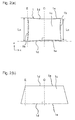
- Fig. 1(a) illustrates a piezoelectric ceramic plate 1 of this embodiment.
- This piezoelectric ceramic plate 1 has a pair of rectangular main surfaces 1 each having a pair of approximately parallel sides 1a opposing each other and another pair of sides 1b, a pair of first side surfaces 1d opposing each other, and a pair of second side surfaces 1e opposing each other.
- the sides constituting the pair of first side surfaces 1d and located on the sides of the main surfaces 1c are sides 1a of the main surfaces 1c.
- the pair of first side surfaces 1d are approximately parallel to each other.
- Fig. 1(b) is a SEM photograph for observing the surface of the piezoelectric ceramic plate 1 from obliquely above the main surface 1c so that the first side surface 1d and the main surface 1c could be confirmed.
- naked surface refers to a surface that has not been processed after firing as illustrated in Fig. 1 (b) and that is constituted of crystal grains (ceramic grains) with rounded corners.
- the pair of second side surfaces 1e and the pair of main surfaces 1c are also baked surfaces, and all the circumferences are baked surfaces.
- the distance between the pair of first side surfaces 1d measured at the center in the longitudinal direction (the x-axis direction) of the first side surfaces 1d is denoted by Lc and the distance between the pair of first side surfaces 1d measured at ends in the longitudinal direction (the x-axis direction) of the first side surfaces 1d is denoted by Le
- the ratio of the difference ⁇ L between Le and Lc to Lc is 1.0% or less.
- ⁇ L/Lc is 0.4% or less, even 0.2% or less, and still 0.1% or less.
- the difference ⁇ L is a value obtained by subtracting the shorter one from the longer one so as to be positive.
- the distance between the first side surfaces 1d can be measured, for example, with a caliper or an image size measuring device (for example, a CNC image measuring device).
- a straight line connecting both ends of one side 1a of the main surface 1c of the piezoelectric ceramic plate 1 is drawn, a perpendicular C (dashed dotted line) is drawn to the middle point between both the ends located on that straight line, intersections of the perpendicular C with the pair of sides 1a of the main surface 1c are determined, and then the distance between the intersections is denoted by Lc.
- a line E located at either one of both the ends of one side 1a and parallel to the perpendicular C is drawn, intersections of the line E with the pair of sides 1a are determined, and then the distance between the intersections is denoted by Le.
- the piezoelectric ceramic plate 1 of this embodiment has a ⁇ L/Lc of 1.0% or less, it can be controlled to have a prescribed shape and prescribed dimensions without performing any processing such as cutting and polishing, so that a piezoelectric ceramic plate 1 accurate in shape and dimensions can be easily obtained and the manufacturing cost can be reduced. Moreover, because of omission of processing after firing, breakage such as chipping and fracture of a thin piezoelectric ceramic plate 1 can be reduced.
- Fig. 1 shows a piezoelectric ceramic plate 1 having a pair of rectangular main surfaces 1c
- a piezoelectric ceramic plate 1 having a pair of trapezoidal main surfaces 1c may of course be available as illustrated in Fig. 2(b) .
- Le and Lc in this case are determined by drawing a straight line connecting both ends of the shorter one of a pair of sides 1a of the main surface 1c, then drawing a perpendicular C (dashed dotted line) to the middle point on that straight line located between both ends of the side 1a, and then drawing a line E located at either one of both ends of one side 1a and parallel to the perpendicular C.
- the pair of main surfaces 1c do not have to be baked surfaces although the case where they are baked surfaces is shown in Fig. 1 .
- Employing baked surfaces also as the pair of main surfaces 1c eliminates the necessity of processing the main surfaces 1c of the piezoelectric ceramic plate 1 after firing.
- the piezoelectric ceramic plate 1 is preferably one having a ( ⁇ L/L) of 1.0% or less even when the area of the main surface 1c is 360 mm 2 or more, and further having a ( ⁇ L/Lc) of 1.0% or less even when the area of the main surface 1c is 1000 mm 2 or more.
- the area of the main surface 1c can be determined as the product of Lc and the distance between both ends of the side 1a.
- the piezoelectric ceramic plate 1 has no internal electrodes, it preferably has a ( ⁇ L/Lc) of 1.0% or less even when the thickness thereof is 50 ⁇ m or less, even 30 ⁇ m or less in the event that the main surface 1c is as wide in area as described above.
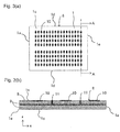
- Fig. 3 illustrates a first embodiment of an electronic component, and this electronic component has a plate-shaped substrate 8 having an internal electrode 5 in a piezoelectric ceramic plate 1.
- the electronic component has a plurality of surface electrodes 10 formed on the surface of the plate-shaped substrate 8, and a via hole conductor 11 connected to the internal electrode 5, extending in the thickness direction of the piezoelectric ceramic plate 1 (the z-axis direction), and led to the surface of the plate-shaped substrate 8, and the piezoelectric ceramic plate 1 has a pair of second side surfaces 1e each being a baked surface.
- the first side surfaces 1d and the second side surfaces 1e of the piezoelectric ceramic plate 1 are baked surfaces, and the main surfaces 1c of the piezoelectric ceramic plate 1 are also baked surfaces. While the side surfaces 1d and 1e of the piezoelectric ceramic plate 1 are formed of side surfaces of two piezoelectric layers 9, it is not discernible to the naked eye, and the two layers together form the side surfaces 1d and 1e of the piezoelectric ceramic plate 1. Since the internal electrodes 5 serve as the boundaries between the piezoelectric layers 9, the number of the piezoelectric layers 9 stacked can be counted on the basis of the number of the internal electrodes 5 stacked.
- the size of the main surface 1c of the piezoelectric ceramic plate 1 is 360 mm 2 or more, or even 1000 mm 2 or more, and the thickness of the piezoelectric ceramic plate 1 having the internal electrode 5 is 150 ⁇ m or less, 100 ⁇ m or less, 60 ⁇ m or less, or even 50 ⁇ m or less.
- the ( ⁇ L/Lc) is 1.0% or less.
- the ( ⁇ L/Lc) is determined by measuring the distance between the pair of first side surfaces 1d of the piezoelectric ceramic plate 1 as illustrated in Fig. 2 with a caliper, an image size measuring device, or the like.
- a 40 ⁇ m thick electronic component with a size of 40 mm x 30 mm is produced using a conventional piezoelectric ceramic plate
- its ⁇ L is several hundred micrometers or more at the time of firing up, and processing is required after the firing.
- the ⁇ L is 200 ⁇ m or less and the distance between the first side surfaces 1d after firing of the piezoelectric ceramic plate 1 satisfies the condition that ⁇ L/Lc is 1.0% or less, and processing is not required after firing. Accordingly, since the electronic component of this embodiment is slightly deformed by firing, an electronic component with a desired shape and desired dimensions can be obtained without being processed after firing and the manufacturing cost can be reduced. Fracture, chipping, and so on caused by processing can also be reduced.
- the electronic component may have three or more piezoelectric layers 9 and two or more layers of internal electrodes 5.
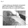
- Fig. 4 shows a state where an electronic component with a size of 35 mm x 116 mm and a thickness of 40 ⁇ m is held with fingers.
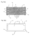
- Fig. 5 illustrates a second embodiment of an electronic component, which has a plate-shaped substrate 8 and a pair of external electrodes 17 which are disposed on opposing second side surfaces 1e of the piezoelectric ceramic plate 1 and connected alternately to internal electrodes 5.
- the pair of second side surfaces 1e on which the external electrodes 17 of the piezoelectric ceramic plate 1 are disposed are processed surfaces.
- the external electrodes 17 are disposed on these processed surfaces, and the internal electrodes 5 and the external electrodes 17 are connected together.
- the processed surface is a surface resulting from processing of a baked surface, and may be a cut surface, a polished surface or the like.
- the entire pair of second side surfaces 1e of the piezoelectric ceramic plate 1 may be processed surfaces, for example, it is also possible that only a limited part of the second side surfaces 1e is processed surfaces such that a part of the second side surfaces 1e on which external electrodes 17 are to be disposed is processed surfaces.
- the pair of first side surfaces 1d of the piezoelectric ceramic plate 1 on which no external electrodes 17 are disposed are baked surfaces.
- the internal electrode 5 is configured as a partial electrode formed on a part of the piezoelectric layer 9 as illustrated in Fig. 5(b) , and a part of the internal electrode 5 is exposed in a second side surface 1e of the piezoelectric ceramic plate 1 and is connected to an external electrode 17.
- the distance between the first side surfaces 1d, which are baked surfaces, of the piezoelectric ceramic plate 1 satisfies the condition that ⁇ L/Lc is 1.0% or less. This can eliminate the necessity of processing the first side surfaces 1d of the piezoelectric ceramic plate 1, and easily affords an electronic component accurate in shape and dimensions, and also can reduce the manufacturing cost.
- the internal electrodes 5 contain Ag as a main component and may contain Pd within a range of up to 35% by mass, even within a range of up to 30% by mass in addition to Ag.
- the piezoelectric ceramic plate 1 (piezoelectric layer 9) is a material including a plurality of crystal grains 2 containing a lead zirconate titanate-type crystal (henceforth also simply referred to as a PZT-type crystal) containing Zn and Bi, and crystal grain boundaries 3 existing between the crystal grains 2 as illustrated in Fig. 6 , or alternatively, it may be a material consisting of the crystal grains 2 and the crystal grain boundaries 3.
- the crystal grains 2 desirably include crystal grains 2 in which Ci is less than Cb (Ci ⁇ Cb) in local elemental analysis performed at the inside of the crystal grain 2 and at an area including the crystal grain boundary 3 (henceforth sometimes referred to as "on a crystal grain boundary 3") both located in a cross section of the piezoelectric ceramic plate 1, followed by comparison of the content Ci of at least one element of Zn and Bi at the inside of the crystal grain 2 with the content Cb thereof at the crystal grain boundary 3 adjoining the crystal grain 2.
- a crystal grain 2 in which Ci is less than Cb is called a "first crystal grain 2a” and a crystal grain 2 in which there is no difference between Ci and Cb for both Zn and Bi or Ci is greater than Cb (Ci ⁇ Cb) is called a “second crystal grain 2b.
- the first crystal grain 2a is a crystal grain in which the content of at least one of Zn and Bi is greater on the crystal grain boundary 3 than that at the inside of the first crystal grain 2a in local elemental analysis performed at the inside of the first crystal grain 2a and on the crystal grain boundary 3 adjoining the first crystal grain 2a, followed by comparison of their content of Zn and Bi.
- the crystal grain boundaries 3 contain substantially no amorphous phase containing Li, B or the like, which is a component to accelerate sintering, or substantially no crystal phase other than PZT-type crystals (heterogeneous phase). Accordingly, the piezoelectric ceramic plate 1 is small in change with time of insulation resistance and deterioration of piezoelectric properties both caused by persistence of those phases.
- the content of Zn and Bi at the inside of the crystal grain 2 and that at the crystal grain boundary 3 can be determined, for example, by observing a cross section of the piezoelectric ceramic plate 1 with a scanning electron microscope (SEM) or a transmission electron microscope (TEM), and then performing local elemental analysis of Zn and Bi at the inside of the crystal grain 2 and at the crystal grain boundary 3 adjoining the crystal grain 2.
- SEM scanning electron microscope
- TEM transmission electron microscope
- the local elemental analysis may be performed, for example, by using energy dispersive X-ray spectroscopy (EDS), a field emission electron probe micro analyzer (FE-EPMA), Auger electron spectrometry (AES), a transmission electron microscope (TEM), or the like.
- EDS energy dispersive X-ray spectroscopy
- FE-EPMA field emission electron probe micro analyzer
- AES Auger electron spectrometry
- TEM transmission electron microscope
- the above-mentioned elemental analyzers differ in spatial resolution; for example, when a transmission electron microscope (TEM) is used, its spatial resolution is a few nanometers, and when Auger electron spectrometry (AES) is used, its spatial resolution is several tens of nanometers. Therefore, the measurement performed on the crystal grain boundary 3 substantially results in the comparison of the result measured at the crystal grain boundary 3 and a vicinity thereof as far as a few nanometers (TEM) or a several tens of nanometers (AES) with the result measured at the center of the crystal grain 2.
- TEM transmission electron microscope
- AES Auger electron spectrometry
- the center (the area centroid of a cross section) of the crystal grain 2 has been taken as an example of a measurement point of the inside of the crystal grain 2, an area where the distance from the crystal grain boundary 3 is equal to or greater than the spatial resolution of an elemental analyzer in the crystal grain 2 may be analyzed and assessed as the inside of the crystal grain 2 when an elemental analyzer with high spatial resolution, such as a TEM, is used.
- an elemental analyzer with high spatial resolution such as a TEM
- the piezoelectric ceramic plate 1 of this embodiment includes a crystal grain boundary 3 with a thickness of 10 nm or less (about 1 to 5 nm), and it is expected that the elemental analysis performed on the crystal grain boundary 3 includes information of the inside of a crystal grain 2 at least a few nanometers away from the crystal grain boundary 3, namely, information of a vicinity of the crystal grain boundary 3 of the crystal grain 2, which is at the very surface of the crystal grain 2.
- the first crystal grain 2a in the piezoelectric ceramic plate 1 of this embodiment has a layer that is rich in at least one of Zn and Bi at the immediate vicinity of the crystal grain boundary 3 (in the vicinity of the surface of the crystal grain 2) and the thickness of the layer is expected to be a few nanometers.
- the area including a crystal grain boundary 3 as referred to herein shall include a surface layer of a crystal grain 2 extending within a few nanometers from the crystal grain boundary 3.
- the measurement of elemental analysis can be performed, for one crystal grain 2, at least at one point within the crystal grain 2 and at one point within an area including a crystal grain boundary 3 (a grain boundary located between two planes or a triple point) located closest to the measurement point within the crystal grain 2, followed by comparison of the measurements.
- a crystal grain boundary 3 a grain boundary located between two planes or a triple point
- the Zn content within the crystal grain 2 is denoted by Ci(Zn) and the Zn content in the area including a crystal grain boundary 3 adjoining the crystal grain 2 is denoted by Cb(Zn)
- the ratio of Cb (Zn) to Ci (Zn) (Cb (Zn) /Ci(Zn)) is not less than 1. 04 and not more than 2.0 in mass ratio.
- the Bi content within the crystal grain 2 is denoted by Ci (Bi) and the Bi content in the area including a crystal grain boundary 3 adjoining the crystal grain 2 is denoted by Cb(Bi)
- the ratio of Cb(Bi) to Ci(Bi) is 1.03 or more, even 1.05 or more, in mass ratio.
- Such ratios make it possible to achieve densification at low temperature.
- (Cb(Bi)/Ci(Bi)) is preferably 2.0 or less, even 1.8 or less, in mass ratio.
- the percentage of the first crystal grains 2a is preferably 80% or more of the crystal grains 2 constituting the piezoelectric ceramic plate 1 as expressed by the ratio of the number of the first crystal grains 2a to the total number of the first crystal grains 2a and the second crystal grains 2b (henceforth referred to as the number of the crystal grains 2) . Adjusting the percentage of the first crystal grains 2a to 80% or more or even 90% or more affords a piezoelectric ceramic plate 1 that slightly deforms even if it is densified in a thin shape and contains a small amount of amorphous phase or heterogeneous phase.
- the percentage of the first crystal grains 2a in the crystal grains 2 composed of the first crystal grains 2a and the second crystal grains 2b can be determined by extracting at least 10 arbitrary crystal grains 2 through observation of a cross section of the piezoelectric ceramic plate 1 with a scanning electron microscope (SEM) or a transmission electron microscope (TEM), performing local elemental analysis of Zn and Bi at the inside of the crystal grains 2 and crystal grain boundaries 3 adjoining the crystal grains 2, and calculating the ratio of the number of the first crystal grains 2a to the number of the crystal grains 2 measured.
- SEM scanning electron microscope
- TEM transmission electron microscope
- the piezoelectric ceramic plate 1 of this embodiment is preferably composed of PZT-type crystal grains 2 and crystal grain boundaries 3 existing between the crystal grains 2, and preferably contains substantially no crystal phase other than the PZT-type crystal, that is, a crystal phase poor in piezoelectric properties or insulation resistance, in terms of maintaining stable insulation resistance or stable piezoelectric properties.
- substantially no crystal phase other than the PZT-type crystal (henceforth referred to as a heterogeneous phase) is contained” means that no heterogeneous phase is found in a lattice image with a transmission electron microscope (TEM) or that in X-ray diffraction (XRD) measurement of a cross section of the piezoelectric ceramic plate 1 using a Cuk ⁇ ray, only peaks derived from the PZT-type crystal are observed and there are substantially no other peaks derived from heterogeneous phases.
- TEM transmission electron microscope
- XRD X-ray diffraction
- the phrase "there are substantially no peaks derived from heterogeneous phases other than the PZT-type crystal in X-ray diffraction measurement using a Cuk ⁇ ray” means that the diffraction peak intensity of the heterogeneous phases is 3 or less when the diffraction peak intensity of (111) of the PZT-type crystal is taken as 100.
- a tangent line is drawn at both sides of a diffraction peak and the diffraction peak intensity is expressed by the length to the peak in a direction perpendicular to the tangent line.
- the piezoelectric ceramic plate 1 is not affected greatly with respect to its piezoelectric properties and can be suitably used.
- the piezoelectric ceramic plate 1 of this embodiment preferably contains substantially no alkali metal element such as Li and Na and substantially no B (boron). If an alkali metal element, such as Li and Na, and B (boron) are added when firing a PZT-type crystal at low temperature, a liquid phase is formed and sintering properties are improved. However, amorphous phases or crystal phases other than the PZT-type crystal remain in crystal grain boundaries 3 of crystal grains 2 of the PZT-type crystal, and accordingly insulation resistance may decrease with time or piezoelectric properties may deteriorate. In some cases, the alkali metal element, such as Li and Na, and B (boron) may inevitably be contained as impurities in the piezoelectric ceramic plate 1. Accordingly, the phrase "substantially no alkali metal element, such as Li and Na, and substantially no B (boron) are contained" means that these elements are not added positively during the process of manufacturing the piezoelectric ceramic plate 1.
- the piezoelectric ceramic plate 1 of this embodiment preferably has a porosity of 0.25% or less.
- a density of 7.7 g/cm 3 or more, even 7.8 g/cm 3 or more is attained, and mechanical loss can be reduced, so that a piezoelectric ceramic plate 1 which is prone to little deterioration or variation of piezoelectric properties is obtained.
- the average grain diameter of the crystal grains 2 in the piezoelectric ceramic plate 1 of this embodiment is preferably 1.0 to 4.0 ⁇ m. If the average grain diameter of the crystal grains 2 is excessively small, the piezoelectric properties deteriorate. If the average grain diameter is excessively large, the hysteresis becomes larger and the piezoelectric ceramic plate becomes prone to generate heat when driven as an electronic component. Adjusting the average grain diameter of the crystal grains 2 to a range of 1.0 to 4.0 ⁇ m makes it possible to maintain necessary piezoelectric properties and inhibit heat generation when the piezoelectric ceramic plate is driven as an electronic component.
- the piezoelectric ceramic plate 1 includes the crystal grains 2 containing a lead zirconate titanate-type crystal containing Zn and Bi and the crystal grain boundaries 3.
- the crystal grains 2 are of a composite perovskite-type compound, and it is desirable that the crystal grains 2 contain Sb, Cu, Ni, and Nb in addition to Pb, Zr, Ti, Zn, and Bi as metal components, and it is desirable that the crystal grains 2 further contain at least one of Sr and Ba if needed.
- the composition of the piezoelectric ceramic plate 1 is represented by a first component represented by the following composition formula and a second component composed of a Bi oxide and a Zn oxide.
- M represents at least one element of Cu and Ni.
- x, y, a, b, and c satisfy the following relational expressions: 0 ⁇ x ⁇ 0.14 , 0 ⁇ y ⁇ 0.14 x + y ⁇ 0.04 , 0.01 ⁇ a ⁇ 0.12 , 0 ⁇ b ⁇ 0.015 , and and 0.42 ⁇ c ⁇ 0.58.
- ⁇ is not less than 0.1 and not more than 2.0. While ⁇ is defined as the total amount of Zn and Bi as the second component in terms of oxides (ZnO and Bi 2 O 3 , respectively), it may be an amount in terms of a composite oxide of Zn and Bi, such as Bi 38 ZnO 58 , Bi 38 ZnO 60 , Bi 48 ZnO 73 , and BiZnO.
- the ratio between Zn and Bi (Bi/Zn) in the second component is preferably 1 ⁇ (Bi/Zn) ⁇ 48 in element ratio.
- a large piezoelectric strain constant can be obtained by setting a as 0.05 ⁇ a ⁇ 0.12
- a large piezoelectric output constant g 31 can be obtained by setting a as 0.01 ⁇ a ⁇ 0.05.
- a piezoelectric ceramic plate 1 containing PZT as a main component there is an MPB (morphotropic phase boundary) that exhibits a maximum value of a piezoelectric strain constant when the solid solution ratio of PbZrO 3 to PbTiO 3 is varied.
- this MPB and a composition close thereto are used. Since this MPB varies depending on the values of x, y, a, and b, the value of c was determined within a composition range where an MPB can be captured within the composition ranges of x, y, a and b.
- the reason why the mass ratio ⁇ (%) of the second component (Zn oxide and Bi oxide) to the first component is adjusted to 0.1 ⁇ ⁇ ⁇ 2.0 is that in this range, a Zn oxide and a Bi oxide form a liquid phase during firing to wet crystal grains 2 containing a PZT-type crystal, and the sintering properties are enhanced, so that the whole of the ceramic is sintered uniformly and warp and deformation can be reduced even with a plate-shaped piezoelectric ceramic plate 1 that is small in thickness and large in area, and Zn and Bi dissolve in a PZT-type crystal after sintering, so that piezoelectric properties can be improved.
- the ratio of Zn to Bi (Bi/Zn) is preferably adjusted to 1 ⁇ (Bi/Zn) ⁇ 48 in element ratio. Use of such a ratio allows the second component to form a liquid phase at low temperature and makes it possible to achieve uniform sintering of the whole ceramic.
- the piezoelectric ceramic plate 1 of this embodiment can be prepared as follows. For example, a mixed material of a calcined powder of a PZT-type crystal containing a first component and a powder containing a second component (Zn oxide and Bi oxide) is formed into a sheet by a well-known sheet forming method and then fired at 900 to 1050°C in the atmosphere. As to an electronic component, an internal electrode paste is applied to a green sheet to form an internal electrode pattern. A plurality of green sheets on which such an internal electrode pattern has been formed are stacked, and finally, a green sheet on which an internal electrode pattern has not been formed is stacked to form a plate-shaped substrate compact, which is then fired at 900 to 1050°C in the atmosphere.
- the second component (Bi oxide and Zn oxide) forms a liquid phase, for example, at a low temperature of about 750°C and can fully wet crystal grains 2 of a PZT-type crystal at a temperature lower than the firing temperature.
- sintering properties can be improved and the entire piezoelectric ceramic plate 1 shrinks approximately uniformly, and Bi and Zn dissolve in the PZT-type crystal after sintering.
- the piezoelectric ceramic plate 1 after sintering includes crystal grains 2 of the PZT-type crystal as depicted in Fig. 6 , and it is desirable that first crystal grains 2a are included in the crystal grains 2.
- a calcined powder of a PZT-type crystal containing Zn is prepared, for example.
- powders of PbO, ZrO 2 , TiO 2 , and ZnO as feedstock and, optionally, powders of Sb 2 O 3 , CuO, NiO, Nb 2 O 5 , SrCO 3 , and BaCO 3 are weighed and mixed. Subsequently, the mixture is dehydrated, dried, and then calcined at a maximum temperature of 850 to 950°C for 1 to 3 hours.
- the resulting calcined powder of the PZT-type crystal is a calcined powder including the first component.
- the calcined powder obtained is milled again with a ball mill or the like so as to bring the average grain diameter D 50 into a range of 0.5 to 0.7 ⁇ m, for example.
- the degree of formation of a PZT-type crystal it is preferable to adjust the degree of formation of a PZT-type crystal appropriately.
- the peak intensity I 1 of a peak (101) (2 ⁇ ⁇ 30°) and the peak intensity I 2 of a peak (111) (2 ⁇ ⁇ 38°) of a PZT-type crystal are used.
- the intensity ratio of I 2 to I 1 , I 2 /I 1 is preferably adjusted to 0.130 to 0.160.
- I 2 /I 1 of a calcined powder is within a range of 0.130 to 0.160, the formation of the PZT-type crystal advances appropriately, and the sintering properties are improved by the addition of the second component (Zn oxide and Bi oxide). Moreover, Zn and Bi are incorporated into a surface layer of the PZT-type crystal along with the grain growth during the sintering stage and they sinter in a temperature range of 900 to 1050°C without remaining as liquid phase components.
- I 2 /I 1 of the calcined powder when I 2 /I 1 of the calcined powder is less than 0.130, the formation of a PZT-type crystal is insufficient and, accordingly, an effect of improving sintering properties may not be obtained even if the second component (Zn oxide and Bi oxide) is added.
- I 2 /I 1 of the calcined powder is larger than 0.160, the formation of a PZT-type crystal excessively advances and, accordingly, Zn and Bi may be difficult to dissolve in a surface layer of the PZT-type crystal even if the second component (Zn oxide and Bi oxide) is added.
- the peak intensity I 1 of a peak (101) (2 ⁇ ⁇ 30°) and the peak intensity I 2 of a peak (111) (2 ⁇ ⁇ 38°) of a PZT-type crystal are used is that it is believed that other peaks vary in peak position or pattern profile with change of the degree of formation (crystal phase) whereas the peak (101) (2 ⁇ ⁇ 30°) and the peak (111) (2 ⁇ ⁇ 38°) only vary in the intensity ratio and do not vary in peak position or pattern profile even if the degree of formation is varied, and therefore these peaks are best suited to indicate the degree of formation of a PZT-type crystal.
- powders of the second component Zn oxide and Bi oxide, for example, ZnO and Bi 2 O 3
- a calcined powder of a PZT-type crystal As to the second component, the respective powders thereof may be added to a calcined powder, or a mixed powder prepared by mixing only the second component powders beforehand may be added to a calcined powder.
- a composite oxide containing Zn and Bi herein referred to as a BZ oxide
- the synthesis can be performed by mixing prescribed amounts of Zn oxide and Bi oxide, dehydrating and drying the resulting mixture, and then calcining the mixture, for example, in the air at 600 to 720°C for 1 to 3 hours.
- the average grain diameter D 50 of the second component is preferably adjusted to a range of 0.5 to 0.7 ⁇ m, especially, so as to be smaller than the average grain diameter (D 50 ) of the calcined powder of a PZT-type crystal, by using a ball mill or the like.
- the calcined powder of a PZT-type crystal to which the second component have been added is mixed with a binder, and then formed into a desired shape using a well-known forming method, such as press forming and sheet forming such as a doctor blade method.
- the prepared compact is fired at 900 to 1050°C in the atmosphere.
- Li, B, and the like which form a liquid phase, have been added in order to fire a PZT-type crystal at low temperature.
- a piezoelectric ceramic plate 1 prepared using such additives can be fired at low temperature, but its insulation resistance drops with time or its piezoelectric properties are deteriorated due to the presence of an amorphous phase or a crystal phase other than the PZT-type crystal in grain boundaries of crystal grains of the PZT-type crystal.
- the piezoelectric ceramic plate 1 of this embodiment exhibits great sintering properties and forms a dense material having a porosity of 0.25% or less and a density of 7.7 g/cm 3 or more even if it is fired at a low temperature of 900 to 1050°C because a Zn oxide and a Bi oxide, which are a second component, form a liquid phase to wet crystal grains 2 of a PZT-type crystal. Moreover, Zn and Bi that have formed a liquid phase dissolve in a surface layer of the crystal grains 2 of the PZT crystal after the sintering, so that a piezoelectric ceramic plate 1 in which the thickness of crystal grain boundaries 3 is 10 nm or less (about 1 to 5 nm) is formed.
- the piezoelectric ceramic plate 1 is a material including first crystal grains 2a, namely, first crystal grains 2a being smaller in the content of at least one element of Zn and Bi than an area including crystal grain boundaries 3 at the inside of the crystal grains 2 of the PZT-type crystal, in other words, first crystal grains 2a having a layer rich in at least one of Zn and Bi in the vicinity of crystal grain boundaries 3 (the surface layer of the crystal grains 2) of the crystal grains 2 of the PZT-type crystal.
- the piezoelectric ceramic plate 1 is a material excellent in piezoelectric properties, which is composed of a plurality of crystal grains 2 of a PZT-type crystal and crystal grain boundaries 3 existing between the crystal grains 2, and in which first crystal grains 2a are included in the crystal grains 2 and substantially no crystal phase other than the PZT-type crystal and substantially no amorphous phase are present at the crystal grain boundaries 3.
- a volume resistivity of 1 G ⁇ •m or more is exhibited even after a lapse of 100 hours at 85°C, and insulation degradation during continuous driving can be inhibited.
- the second component forms a liquid phase at about 750°C and the whole of the ceramic starts sintering uniformly at the time of firing. Accordingly, deformation of the piezoelectric ceramic plate 1 during a sintering process tends to be inhibited even if the piezoelectric ceramic plate 1 is thin.
- the piezoelectric ceramic plate 1 of this embodiment is suitably used especially in an electronic component having a thickness of 150 ⁇ m or less, especially 50 ⁇ m or less.
- the piezoelectric ceramic plate 1 can be used as various electronic components, such as a ceramic filter, an ultrasonic oscillator, a piezoelectric buzzer, a piezoelectric ignition unit, an ultrasonic motor, a piezoelectric fan, a piezoelectric sensor, and a piezoelectric actuator.
- a piezoelectric actuator is an actuator utilizing displacement or power generated through a piezoelectric phenomenon as a mechanical driving source, and it is one of those that are recently attracting attention in the mechatronics field.
- a piezoelectric actuator is a solid element utilizing a piezoelectric effect, and it has distinguishing characteristics, such as less power consumption, greater response speed, larger amount of displacement, less heat generation, and smaller dimension and weight as compared with conventional electromagnetic actuators having a structure in which a coil is wound around a magnetic material.
- a multi-layer piezoelectric actuator from which larger displacement or larger generated force can be obtained at lower voltages is practically used for automatically focusing a camera for opening and closing a fuel injection valve of a vehicle-installed injector and as an acoustic component, such as a piezoelectric loudspeaker.
- the powders were weighed such that the first component might have the composition of Table 1 with the formula Pb 1-x-y Sr x Ba y Ti 1-a-b-c (Zn 1/3 Sb 2/3 ) a (M 1/3 Nb 2/3 ) b Zr c O 3 , and then wet mixed with a ball mill for 24 hours. MisCuorNi.
- this mixture was dehydrated, dried, and then calcined at the calcination temperature shown in Table 1 for 3 hours, and the calcined material was wet ground again with a ball mill for 24 hours, thereby yielding a calcined powder having a D 50 of 0.5 to 0.7 ⁇ m.
- an additive having a D 50 of 0.5 to 0.7 ⁇ m shown in Table 1 was added in an amount (% by mass) shown in Table 1, expressed by a ratio relative to 100% by mass of the first component, and an organic binder was mixed therewith, and then a green sheet having a thickness of 30 ⁇ m was prepared using a doctor blade method.
- a green sheet prepared was screen printed an internal electrode paste containing Ag and Pd, and 15 green sheets with an internal electrode paste printed thereon were stacked and a green sheet with no internal electrode paste printed thereon was stacked lastly.
- a plate-shaped substrate compact was prepared.
- the plate-shaped substrate compact prepared was debindered and then fired in the atmosphere under the firing conditions shown in Table 1, followed by cooling. Thus, a plate-shaped substrate with internal electrodes exposed alternately in its both end surfaces was obtained.
- a multi-layer piezoelectric actuator that is an electronic component for assessing piezoelectric properties was obtained by forming an external electrode through burning of an Ag paste on both end surfaces of the resultant plate-shaped substrate, and then performing a polarization treatment.
- the thickness per layer of the piezoelectric layers (the thickness between the electrodes) of the piezoelectric ceramic plate was 25 ⁇ m.
- the porosity of the piezoelectric layer was determined by polishing a cross section of the plate-shaped substrate, observing the polished surface by using a scanning electron microscope (SEM), and image processing a photograph of the piezoelectric layer.
- SEM scanning electron microscope
- a SEM photograph of the polished surface thermally etched (in the atmosphere, at 950°C for 3 hours) was image processed, and the average grain diameter of crystal grains in the piezoelectric layer was determined with the equivalent circle diameter of the cross-sectional area determined from the profile of a crystal grain constituting the piezoelectric layer regarded as the diameter of the crystal grain.
- the density of the piezoelectric layer the bulk density of the plate-shaped substrate was determined according to the Archimedes method, and the bulk density was regarded as the density of the piezoelectric layer.
- composition of the plate-shaped substrate was examined by ICP emission spectroscopic analysis. It was thereby found that the composition of the piezoelectric layer agreed with the composition used in the preparation within a margin of error.
- piezoelectric properties As to piezoelectric properties, an aging treatment was applied at 100°C to a polarized electronic component, and then a specimen with a size of 12 x 3 mm was cut out.
- the piezoelectric strain constant d 31 of the electronic component was determined by performing a polarization treatment through application of a DC voltage to two surface electrodes formed on both sides of the specimen, and then measuring a vibration mode in the longitudinal direction.
- the piezoelectric strain constant d 31 determined is shown in Table 1.
- a plate-shaped substrate for deformation measurement was prepared.
- a 25 ⁇ m thick green sheet was prepared by a doctor blade method, and using an internal electrode paste, the internal electrode paste was printed on the whole area of 14.8 mm x 28 mm on the green sheet.
- a green sheet on which the internal electrode paste had not been printed was stacked on the printed side of the green sheet on which the internal electrode paste had been printed, and the stack was subjected to debindering and then fired, thereby yielding a plate-shaped substrate.
- the firing conditions were the same as the conditions under which the multi-layer piezoelectric actuator was prepared.
- the plate-shaped substrate obtained was in a rectangular shape having a thickness of 42 ⁇ m (the thickness of the piezoelectric layer was 21 ⁇ m) and a main surface area of 360 mm 2 .
- the deformation of the piezoelectric ceramic plate was assessed with a ratio ( ⁇ L/Lc).
- the measurement of the length of the piezoelectric ceramic plate was performed using a CNC image measuring device. The results are shown in Table 1. [Table 1] Sample No.
- Sample Nos. 1 to 11 afford piezoelectric ceramic plates that deform in an amount of 1% or less and can eliminate or reduce the necessity of processing after firing.
- the samples in which first crystal grains, namely, crystal grains in which the content of at least one of Zn and Bi was larger in crystal grain boundaries adjoining the crystal grains than inside the crystal grains, were present in the piezoelectric layer showed the following results: they were densified to a porosity of 0.25% or less even when they were fired at low temperature; their piezoelectric properties were high and a piezoelectric strain constant d 31 was 250 p•m/V or more; their initial volume resistivity was 80 G ⁇ •m or more; the deterioration with time of their insulation resistance was small as indicated by a volume resistivity of 70 G ⁇ •m or more even after a lapse of 100 hours at 85°C; and the deformation of a piezoelectric ceramic plate was small.
- the samples having a ratio of the first crystal grains of 90% or more had a ratio of the amount of deformation of less than 0.1%.
- the samples containing Cu in their piezoelectric layers maintained high piezoelectric d constants and had greater coercive electric fields than the samples having similar compositions but containing no Cu.
- a first component was prepared, and then a second component was added to the first component.
- An organic binder was mixed therewith, and then a green sheet was prepared using a doctor blade method.
- An internal electrode paste was applied to the entire area of this green sheet, and then a green sheet to which an internal electrode paste had not been applied was stacked on the printed surface of the green sheet to which the internal electrode paste had been applied, followed by debindering and subsequent firing.
- a plate-shaped substrate with a multi-layer structure as illustrated in Fig. 3 having the thickness of a piezoelectric ceramic plate, the area of each of the main surfaces of the piezoelectric ceramic plate, and the thickness of a piezoelectric layer as shown in Table 2.
- a plate-shaped substrate depicted in Fig. 5 and having four piezoelectric layers and three internal electrode layers was prepared using three green sheets to each of which an internal electrode paste had been applied partially and one green sheet to which an internal electrode paste had not been applied.
- Sample Nos. 15 to 19 afford piezoelectric ceramic plates that deform in an amount of 1% or less and can eliminate or reduce the necessity of processing after firing of piezoelectric ceramic plates.
Landscapes
- Engineering & Computer Science (AREA)
- Chemical & Material Sciences (AREA)
- Manufacturing & Machinery (AREA)
- Ceramic Engineering (AREA)
- Materials Engineering (AREA)
- Structural Engineering (AREA)
- Organic Chemistry (AREA)
- Inorganic Chemistry (AREA)
- Composite Materials (AREA)
- Physics & Mathematics (AREA)
- Thermal Sciences (AREA)
- Compositions Of Oxide Ceramics (AREA)
Abstract
Description
- The present invention relates to a piezoelectric ceramic plate, a plate-shaped substrate, and an electronic component.
- Piezoelectric ceramic plates are used for a variety of electronic components, such as a piezoelectric actuator, which utilize, as a mechanical driving source, displacement or force generated via a piezoelectric phenomenon. With broadened use of piezoelectric actuators, multi-layer piezoelectric actuators from which larger displacement or larger generated force can be obtained at lower voltages have become increasingly used.
- Since conventional piezoelectric ceramic plates develop significant deformation (variation in shrinkage) after firing, such piezoelectric ceramic plates are subjected to processing, such as cutting and polishing, after firing in order to control the shape and dimensions of the piezoelectric ceramic plates into prescribed ranges (see, for example, Patent Literature 1).
- Patent DOCUMENT 1: Japanese Unexamined Patent Publication No.
3-54878 - Conventionally, however, there is a problem that the number of steps increases and the manufacturing cost also increases because cutting, polishing or the like is performed after firing in order to control the shape and dimensions of a piezoelectric ceramic plate into prescribed ranges.
- It is an object of the present invention to provide a piezoelectric ceramic plate and a plate-shaped substrate which are capable of reducing processing after firing, and an electronic component.
- The piezoelectric ceramic plate of the present invention is a piezoelectric ceramic plate having a pair of quadrangular main surfaces, a pair of first side surfaces opposing each other, and a pair of second side surfaces opposing each other, wherein the pair of first side surfaces are baked surfaces, and where the distance between the pair of first side surfaces measured at the center in the longitudinal direction of the first side surfaces is denoted by Lc and the distance between the pair of first side surfaces measured at ends in the longitudinal direction of the first side surfaces is denoted by Le, the ratio of the difference ΔL between Le and Lc to Lc (ΔL/Lc) is 1.0% or less.
- The piezoelectric ceramic plate of the present invention is a piezoelectric ceramic plate having a pair of quadrangular main surfaces, a pair of first side surfaces opposing each other, and a pair of second side surfaces opposing each other, wherein the area of each of the main surfaces is 360 mm2 or more, and the pair of first side surfaces are baked surfaces.
- The plate-shaped substrate of the present invention has an internal electrode within a piezoelectric ceramic plate.
- The electronic component of the present invention is an electronic component including a surface electrode disposed on a surface of the plate-shaped substrate mentioned above, and a via hole conductor connected to the internal electrode, extending in the thickness direction of the piezoelectric ceramic plate, and led to the surface of the plate-shaped substrate, wherein the pair of second side surfaces of the piezoelectric ceramic plate are baked surfaces.
- The electronic component of the present invention is an electronic component including the plate-shaped substrate mentioned above, and an external electrode disposed on each of the second side surfaces of the piezoelectric ceramic plate and connected to the internal electrode, wherein the electronic component has a processed surface as each of the second side surfaces of the piezoelectric ceramic plate, and the external electrode is disposed on the processed surface.
- With the piezoelectric ceramic plate of the present invention, processing after firing can be reduced. In addition, with the plate-shaped substrate and the electronic component of the present invention, the manufacturing cost can be reduced.
-
-
Fig. 1 shows a piezoelectric ceramic plate;Fig. 1(a) is a perspective view andFig. 1(b) is a scanning electron microscope (SEM) photograph of a surface extending from a first side surface to a main surface. -
Fig. 2(a) is an explanatory view about the amount of deformation of a piezoelectric ceramic plate the main surface of which has a rectangular shape, andFig. 2 (b) is an explanatory view about the amount of deformation of a piezoelectric ceramic plate the main surface of which has a trapezoidal shape. -
Fig. 3 schematically illustrates a first embodiment of an electronic component;Fig. 3(a) is a schematic plan view, andFig. 3(b) is a cross-sectional view ofFig. 3(a) along line A-A. -
Fig. 4 is a photograph of a state where an electronic component is held by hand. -
Fig. 5 schematically illustrates a second embodiment of an electronic component;Fig. 5 (a) is a schematic longitudinal cross-sectional view, andFig. 5(b) is a schematic transverse cross-sectional view. -
Fig. 6 is an explanatory view illustrating tissue structure of a piezoelectric layer. -
Fig. 7 is a diagram showing the X-ray diffraction result of Sample No. 3. -
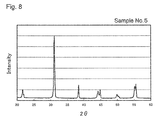
Fig. 8 is a diagram showing the X-ray diffraction result of Sample No. 5. -
Fig. 1(a) illustrates a piezoelectricceramic plate 1 of this embodiment. This piezoelectricceramic plate 1 has a pair of rectangularmain surfaces 1 each having a pair of approximatelyparallel sides 1a opposing each other and another pair ofsides 1b, a pair offirst side surfaces 1d opposing each other, and a pair ofsecond side surfaces 1e opposing each other. The sides constituting the pair offirst side surfaces 1d and located on the sides of themain surfaces 1c aresides 1a of themain surfaces 1c. Thus, the pair offirst side surfaces 1d are approximately parallel to each other. - The pair of
first side surfaces 1d are baked surfaces as illustrated inFig. 1(b). Fig. 1(b) is a SEM photograph for observing the surface of the piezoelectricceramic plate 1 from obliquely above themain surface 1c so that thefirst side surface 1d and themain surface 1c could be confirmed. - The term "baked surface" refers to a surface that has not been processed after firing as illustrated in
Fig. 1 (b) and that is constituted of crystal grains (ceramic grains) with rounded corners. In this embodiment, the pair ofsecond side surfaces 1e and the pair ofmain surfaces 1c are also baked surfaces, and all the circumferences are baked surfaces. - As illustrated in
Fig. 2(a) , where the distance between the pair offirst side surfaces 1d measured at the center in the longitudinal direction (the x-axis direction) of thefirst side surfaces 1d is denoted by Lc and the distance between the pair offirst side surfaces 1d measured at ends in the longitudinal direction (the x-axis direction) of thefirst side surfaces 1d is denoted by Le, the ratio of the difference ΔL between Le and Lc to Lc (ΔL/Lc) is 1.0% or less. In particular, ΔL/Lc is 0.4% or less, even 0.2% or less, and still 0.1% or less. The difference ΔL is a value obtained by subtracting the shorter one from the longer one so as to be positive. The distance between thefirst side surfaces 1d can be measured, for example, with a caliper or an image size measuring device (for example, a CNC image measuring device). - Specifically, as shown by a two-dot chain line in
Fig. 2(a) , a straight line connecting both ends of oneside 1a of themain surface 1c of the piezoelectricceramic plate 1 is drawn, a perpendicular C (dashed dotted line) is drawn to the middle point between both the ends located on that straight line, intersections of the perpendicular C with the pair ofsides 1a of themain surface 1c are determined, and then the distance between the intersections is denoted by Lc. On the other hand, a line E located at either one of both the ends of oneside 1a and parallel to the perpendicular C is drawn, intersections of the line E with the pair ofsides 1a are determined, and then the distance between the intersections is denoted by Le. - Since the piezoelectric
ceramic plate 1 of this embodiment has a ΔL/Lc of 1.0% or less, it can be controlled to have a prescribed shape and prescribed dimensions without performing any processing such as cutting and polishing, so that a piezoelectricceramic plate 1 accurate in shape and dimensions can be easily obtained and the manufacturing cost can be reduced. Moreover, because of omission of processing after firing, breakage such as chipping and fracture of a thin piezoelectricceramic plate 1 can be reduced. - Although
Fig. 1 shows a piezoelectricceramic plate 1 having a pair of rectangularmain surfaces 1c, a piezoelectricceramic plate 1 having a pair of trapezoidalmain surfaces 1c may of course be available as illustrated inFig. 2(b) . Le and Lc in this case are determined by drawing a straight line connecting both ends of the shorter one of a pair ofsides 1a of themain surface 1c, then drawing a perpendicular C (dashed dotted line) to the middle point on that straight line located between both ends of theside 1a, and then drawing a line E located at either one of both ends of oneside 1a and parallel to the perpendicular C. - The pair of
main surfaces 1c do not have to be baked surfaces although the case where they are baked surfaces is shown inFig. 1 . Employing baked surfaces also as the pair ofmain surfaces 1c eliminates the necessity of processing themain surfaces 1c of the piezoelectricceramic plate 1 after firing. - The piezoelectric
ceramic plate 1 is preferably one having a (ΔL/L) of 1.0% or less even when the area of themain surface 1c is 360 mm2 or more, and further having a (ΔL/Lc) of 1.0% or less even when the area of themain surface 1c is 1000 mm2 or more. The area of themain surface 1c can be determined as the product of Lc and the distance between both ends of theside 1a. When the piezoelectricceramic plate 1 has no internal electrodes, it preferably has a (ΔL/Lc) of 1.0% or less even when the thickness thereof is 50 µm or less, even 30 µm or less in the event that themain surface 1c is as wide in area as described above. -
Fig. 3 illustrates a first embodiment of an electronic component, and this electronic component has a plate-shaped substrate 8 having aninternal electrode 5 in a piezoelectricceramic plate 1. In addition, the electronic component has a plurality ofsurface electrodes 10 formed on the surface of the plate-shaped substrate 8, and avia hole conductor 11 connected to theinternal electrode 5, extending in the thickness direction of the piezoelectric ceramic plate 1 (the z-axis direction), and led to the surface of the plate-shaped substrate 8, and the piezoelectricceramic plate 1 has a pair ofsecond side surfaces 1e each being a baked surface. - That is, in this embodiment, the
first side surfaces 1d and thesecond side surfaces 1e of the piezoelectricceramic plate 1 are baked surfaces, and themain surfaces 1c of the piezoelectricceramic plate 1 are also baked surfaces. While theside surfaces ceramic plate 1 are formed of side surfaces of twopiezoelectric layers 9, it is not discernible to the naked eye, and the two layers together form theside surfaces ceramic plate 1. Since theinternal electrodes 5 serve as the boundaries between thepiezoelectric layers 9, the number of thepiezoelectric layers 9 stacked can be counted on the basis of the number of theinternal electrodes 5 stacked. - In such an electronic component, voltage is applied between a
surface electrode 10 and aninternal electrode 5 via avia hole conductor 11 led to the surface of the plate-shaped substrate 8 and thesurface electrode 10. InFig. 3(a) , viahole conductors 11 are omitted. - The size of the
main surface 1c of the piezoelectricceramic plate 1 is 360 mm2 or more, or even 1000 mm2 or more, and the thickness of the piezoelectricceramic plate 1 having theinternal electrode 5 is 150 µm or less, 100 µm or less, 60 µm or less, or even 50 µm or less. - Also in this embodiment, the (ΔL/Lc) is 1.0% or less. The (ΔL/Lc) is determined by measuring the distance between the pair of
first side surfaces 1d of the piezoelectricceramic plate 1 as illustrated inFig. 2 with a caliper, an image size measuring device, or the like. - When, for example, a 40 µm thick electronic component with a size of 40 mm x 30 mm is produced using a conventional piezoelectric ceramic plate, its ΔL is several hundred micrometers or more at the time of firing up, and processing is required after the firing. On the other hand, in the case of an electronic component including the piezoelectric
ceramic plate 1 of this embodiment, the ΔL is 200 µm or less and the distance between the first side surfaces 1d after firing of the piezoelectricceramic plate 1 satisfies the condition that ΔL/Lc is 1.0% or less, and processing is not required after firing. Accordingly, since the electronic component of this embodiment is slightly deformed by firing, an electronic component with a desired shape and desired dimensions can be obtained without being processed after firing and the manufacturing cost can be reduced. Fracture, chipping, and so on caused by processing can also be reduced. - The electronic component may have three or more
piezoelectric layers 9 and two or more layers ofinternal electrodes 5.Fig. 4 shows a state where an electronic component with a size of 35 mm x 116 mm and a thickness of 40 µm is held with fingers. -
Fig. 5 illustrates a second embodiment of an electronic component, which has a plate-shapedsubstrate 8 and a pair ofexternal electrodes 17 which are disposed on opposing second side surfaces 1e of the piezoelectricceramic plate 1 and connected alternately tointernal electrodes 5. The pair ofsecond side surfaces 1e on which theexternal electrodes 17 of the piezoelectricceramic plate 1 are disposed are processed surfaces. Theexternal electrodes 17 are disposed on these processed surfaces, and theinternal electrodes 5 and theexternal electrodes 17 are connected together. The processed surface is a surface resulting from processing of a baked surface, and may be a cut surface, a polished surface or the like. - While the entire pair of second side surfaces 1e of the piezoelectric
ceramic plate 1 may be processed surfaces, for example, it is also possible that only a limited part of thesecond side surfaces 1e is processed surfaces such that a part of thesecond side surfaces 1e on whichexternal electrodes 17 are to be disposed is processed surfaces. - On the other hand, the pair of first side surfaces 1d of the piezoelectric
ceramic plate 1 on which noexternal electrodes 17 are disposed are baked surfaces. - The
internal electrode 5 is configured as a partial electrode formed on a part of thepiezoelectric layer 9 as illustrated inFig. 5(b) , and a part of theinternal electrode 5 is exposed in asecond side surface 1e of the piezoelectricceramic plate 1 and is connected to anexternal electrode 17. - Like the electronic component of
Fig. 3 , the distance between thefirst side surfaces 1d, which are baked surfaces, of the piezoelectricceramic plate 1 satisfies the condition that ΔL/Lc is 1.0% or less. This can eliminate the necessity of processing the first side surfaces 1d of the piezoelectricceramic plate 1, and easily affords an electronic component accurate in shape and dimensions, and also can reduce the manufacturing cost. - In the electronic components of
Figs. 3 and5 , theinternal electrodes 5 contain Ag as a main component and may contain Pd within a range of up to 35% by mass, even within a range of up to 30% by mass in addition to Ag. - The piezoelectric ceramic plate 1 (piezoelectric layer 9) is a material including a plurality of
crystal grains 2 containing a lead zirconate titanate-type crystal (henceforth also simply referred to as a PZT-type crystal) containing Zn and Bi, andcrystal grain boundaries 3 existing between thecrystal grains 2 as illustrated inFig. 6 , or alternatively, it may be a material consisting of thecrystal grains 2 and thecrystal grain boundaries 3. - The
crystal grains 2 desirably includecrystal grains 2 in which Ci is less than Cb (Ci < Cb) in local elemental analysis performed at the inside of thecrystal grain 2 and at an area including the crystal grain boundary 3 (henceforth sometimes referred to as "on acrystal grain boundary 3") both located in a cross section of the piezoelectricceramic plate 1, followed by comparison of the content Ci of at least one element of Zn and Bi at the inside of thecrystal grain 2 with the content Cb thereof at thecrystal grain boundary 3 adjoining thecrystal grain 2. - Regarding at least one element of Zn and Bi, a
crystal grain 2 in which Ci is less than Cb is called a "first crystal grain 2a" and acrystal grain 2 in which there is no difference between Ci and Cb for both Zn and Bi or Ci is greater than Cb (Ci ≥ Cb) is called a "second crystal grain 2b. " In other words, thefirst crystal grain 2a is a crystal grain in which the content of at least one of Zn and Bi is greater on thecrystal grain boundary 3 than that at the inside of thefirst crystal grain 2a in local elemental analysis performed at the inside of thefirst crystal grain 2a and on thecrystal grain boundary 3 adjoining thefirst crystal grain 2a, followed by comparison of their content of Zn and Bi. - Unlike conventional PZT-type piezoelectric ceramic plates, in the piezoelectric
ceramic plate 1, thecrystal grain boundaries 3 contain substantially no amorphous phase containing Li, B or the like, which is a component to accelerate sintering, or substantially no crystal phase other than PZT-type crystals (heterogeneous phase). Accordingly, the piezoelectricceramic plate 1 is small in change with time of insulation resistance and deterioration of piezoelectric properties both caused by persistence of those phases. - The content of Zn and Bi at the inside of the
crystal grain 2 and that at thecrystal grain boundary 3 can be determined, for example, by observing a cross section of the piezoelectricceramic plate 1 with a scanning electron microscope (SEM) or a transmission electron microscope (TEM), and then performing local elemental analysis of Zn and Bi at the inside of thecrystal grain 2 and at thecrystal grain boundary 3 adjoining thecrystal grain 2. - The local elemental analysis may be performed, for example, by using energy dispersive X-ray spectroscopy (EDS), a field emission electron probe micro analyzer (FE-EPMA), Auger electron spectrometry (AES), a transmission electron microscope (TEM), or the like. Herein, the content of Zn and Bi at the inside of the
crystal grain 2 means, for example, the content of Zn and Bi detected by elemental analysis of the center (area centroid of a cross section) of thecrystal grain 2, and the content of Zn and Bi in an area includingcrystal grain boundaries 3 means the content of Zn and Bi detected by elemental analysis of thecrystal grain boundary 3 of thecrystal grain 2 and a vicinity thereof. - The above-mentioned elemental analyzers differ in spatial resolution; for example, when a transmission electron microscope (TEM) is used, its spatial resolution is a few nanometers, and when Auger electron spectrometry (AES) is used, its spatial resolution is several tens of nanometers. Therefore, the measurement performed on the
crystal grain boundary 3 substantially results in the comparison of the result measured at thecrystal grain boundary 3 and a vicinity thereof as far as a few nanometers (TEM) or a several tens of nanometers (AES) with the result measured at the center of thecrystal grain 2. Although the center (the area centroid of a cross section) of thecrystal grain 2 has been taken as an example of a measurement point of the inside of thecrystal grain 2, an area where the distance from thecrystal grain boundary 3 is equal to or greater than the spatial resolution of an elemental analyzer in thecrystal grain 2 may be analyzed and assessed as the inside of thecrystal grain 2 when an elemental analyzer with high spatial resolution, such as a TEM, is used. - The piezoelectric
ceramic plate 1 of this embodiment includes acrystal grain boundary 3 with a thickness of 10 nm or less (about 1 to 5 nm), and it is expected that the elemental analysis performed on thecrystal grain boundary 3 includes information of the inside of acrystal grain 2 at least a few nanometers away from thecrystal grain boundary 3, namely, information of a vicinity of thecrystal grain boundary 3 of thecrystal grain 2, which is at the very surface of thecrystal grain 2. In other words, it is expected that thefirst crystal grain 2a in the piezoelectricceramic plate 1 of this embodiment has a layer that is rich in at least one of Zn and Bi at the immediate vicinity of the crystal grain boundary 3 (in the vicinity of the surface of the crystal grain 2) and the thickness of the layer is expected to be a few nanometers. Accordingly, the area including acrystal grain boundary 3 as referred to herein shall include a surface layer of acrystal grain 2 extending within a few nanometers from thecrystal grain boundary 3. - The measurement of elemental analysis can be performed, for one
crystal grain 2, at least at one point within thecrystal grain 2 and at one point within an area including a crystal grain boundary 3 (a grain boundary located between two planes or a triple point) located closest to the measurement point within thecrystal grain 2, followed by comparison of the measurements. - When the Zn content within the
crystal grain 2 is denoted by Ci(Zn) and the Zn content in the area including acrystal grain boundary 3 adjoining thecrystal grain 2 is denoted by Cb(Zn), it is preferable in thefirst crystal grain 2a that the ratio of Cb (Zn) to Ci (Zn) (Cb (Zn) /Ci(Zn)) is not less than 1. 04 and not more than 2.0 in mass ratio. - Moreover, when the Bi content within the
crystal grain 2 is denoted by Ci (Bi) and the Bi content in the area including acrystal grain boundary 3 adjoining thecrystal grain 2 is denoted by Cb(Bi), it is preferable in thefirst crystal grain 2a that the ratio of Cb(Bi) to Ci(Bi) (Cb(Bi)/Ci(Bi)) is 1.03 or more, even 1.05 or more, in mass ratio. Such ratios make it possible to achieve densification at low temperature. (Cb(Bi)/Ci(Bi)) is preferably 2.0 or less, even 1.8 or less, in mass ratio. - The percentage of the
first crystal grains 2a is preferably 80% or more of thecrystal grains 2 constituting the piezoelectricceramic plate 1 as expressed by the ratio of the number of thefirst crystal grains 2a to the total number of thefirst crystal grains 2a and thesecond crystal grains 2b (henceforth referred to as the number of the crystal grains 2) . Adjusting the percentage of thefirst crystal grains 2a to 80% or more or even 90% or more affords a piezoelectricceramic plate 1 that slightly deforms even if it is densified in a thin shape and contains a small amount of amorphous phase or heterogeneous phase. - The percentage of the
first crystal grains 2a in thecrystal grains 2 composed of thefirst crystal grains 2a and thesecond crystal grains 2b can be determined by extracting at least 10arbitrary crystal grains 2 through observation of a cross section of the piezoelectricceramic plate 1 with a scanning electron microscope (SEM) or a transmission electron microscope (TEM), performing local elemental analysis of Zn and Bi at the inside of thecrystal grains 2 andcrystal grain boundaries 3 adjoining thecrystal grains 2, and calculating the ratio of the number of thefirst crystal grains 2a to the number of thecrystal grains 2 measured. - The piezoelectric
ceramic plate 1 of this embodiment is preferably composed of PZT-type crystal grains 2 andcrystal grain boundaries 3 existing between thecrystal grains 2, and preferably contains substantially no crystal phase other than the PZT-type crystal, that is, a crystal phase poor in piezoelectric properties or insulation resistance, in terms of maintaining stable insulation resistance or stable piezoelectric properties. The phrase "substantially no crystal phase other than the PZT-type crystal (henceforth referred to as a heterogeneous phase) is contained" means that no heterogeneous phase is found in a lattice image with a transmission electron microscope (TEM) or that in X-ray diffraction (XRD) measurement of a cross section of the piezoelectricceramic plate 1 using a Cukα ray, only peaks derived from the PZT-type crystal are observed and there are substantially no other peaks derived from heterogeneous phases. - The phrase "there are substantially no peaks derived from heterogeneous phases other than the PZT-type crystal in X-ray diffraction measurement using a Cukα ray" means that the diffraction peak intensity of the heterogeneous phases is 3 or less when the diffraction peak intensity of (111) of the PZT-type crystal is taken as 100. In a diffraction profile obtained as a result of X-ray diffraction (XRD) measurement, a tangent line is drawn at both sides of a diffraction peak and the diffraction peak intensity is expressed by the length to the peak in a direction perpendicular to the tangent line. If the peak intensity of crystal phases other than PZT-type crystal phases low in piezoelectric properties or insulation resistance (heterogeneous phases) is 3 or less relative to the diffraction peak intensity of (111) of the PZT-type crystal when the diffraction peak intensity of (111) of the PZT-type crystal is taken as 100, the piezoelectric
ceramic plate 1 is not affected greatly with respect to its piezoelectric properties and can be suitably used. - The piezoelectric
ceramic plate 1 of this embodiment preferably contains substantially no alkali metal element such as Li and Na and substantially no B (boron). If an alkali metal element, such as Li and Na, and B (boron) are added when firing a PZT-type crystal at low temperature, a liquid phase is formed and sintering properties are improved. However, amorphous phases or crystal phases other than the PZT-type crystal remain incrystal grain boundaries 3 ofcrystal grains 2 of the PZT-type crystal, and accordingly insulation resistance may decrease with time or piezoelectric properties may deteriorate. In some cases, the alkali metal element, such as Li and Na, and B (boron) may inevitably be contained as impurities in the piezoelectricceramic plate 1. Accordingly, the phrase "substantially no alkali metal element, such as Li and Na, and substantially no B (boron) are contained" means that these elements are not added positively during the process of manufacturing the piezoelectricceramic plate 1. - In terms of denseness, the piezoelectric
ceramic plate 1 of this embodiment preferably has a porosity of 0.25% or less. By forming such a dense piezoelectricceramic plate 1, a density of 7.7 g/cm3 or more, even 7.8 g/cm3 or more is attained, and mechanical loss can be reduced, so that a piezoelectricceramic plate 1 which is prone to little deterioration or variation of piezoelectric properties is obtained. - The average grain diameter of the
crystal grains 2 in the piezoelectricceramic plate 1 of this embodiment is preferably 1.0 to 4.0 µm. If the average grain diameter of thecrystal grains 2 is excessively small, the piezoelectric properties deteriorate. If the average grain diameter is excessively large, the hysteresis becomes larger and the piezoelectric ceramic plate becomes prone to generate heat when driven as an electronic component. Adjusting the average grain diameter of thecrystal grains 2 to a range of 1.0 to 4.0 µm makes it possible to maintain necessary piezoelectric properties and inhibit heat generation when the piezoelectric ceramic plate is driven as an electronic component. - The piezoelectric
ceramic plate 1 includes thecrystal grains 2 containing a lead zirconate titanate-type crystal containing Zn and Bi and thecrystal grain boundaries 3. Thecrystal grains 2 are of a composite perovskite-type compound, and it is desirable that thecrystal grains 2 contain Sb, Cu, Ni, and Nb in addition to Pb, Zr, Ti, Zn, and Bi as metal components, and it is desirable that thecrystal grains 2 further contain at least one of Sr and Ba if needed. - The composition of the piezoelectric
ceramic plate 1 is represented by a first component represented by the following composition formula and a second component composed of a Bi oxide and a Zn oxide. Here, M represents at least one element of Cu and Ni.
First component: Pb1-x-ySrxBayTi1-a-b-c(Zn1/3Sb2/3)a(M1/3Nb2/3)bZrcO3 In the composition formula of the first component, x, y, a, b, and c satisfy the following relational expressions:


- Here, the reason why x, y, a, b, c, and α are limited to the ranges recited above will be described. The reason why the amount of substitution of Sr for Pb, x, is limited as 0 ≤ x ≤ 0.14 is that it is possible to keep the Curie temperature high by substituting a part of Pb by Sr. The reason why the amount of substitution of Ba for Pb, y, is limited as 0 ≤ y ≤ 0.14 is that it is possible to maintain the Curie temperature high and obtain a high piezoelectric strain constant d31 by substituting a part of Pb by Ba.
- The reason why the amount of substitution of (Zn1/3Sb2/3) for Ti, a, is limited as 0.01 ≤ a ≤ 0.12 is that it is possible to obtain a large piezoelectric strain constant d31 and a large piezoelectric output constant g31, to maintain the Curie temperature high, and to maintain a small dielectric loss. When the piezoelectric
ceramic plate 1 of this embodiment is used as a piezoelectric actuator, a large piezoelectric strain constant can be obtained by setting a as 0.05 ≤ a ≤ 0.12, and when it is used as a piezoelectric sensor, a large piezoelectric output constant g31 can be obtained by setting a as 0.01 ≤ a ≤ 0.05. - By limiting the amount of substitution of (M1/3Nb2/3) for Ti, b, as 0 ≤ b ≤ 0.015, a large coercive electric field can be achieved while inhibiting drop of a piezoelectric d constant. While Ni and Cu are used as M, when Cu is used as M, a piezoelectric
ceramic plate 1 with a large coercive electric field can be formed while maintaining a particularly high piezoelectric d constant, and deterioration in displacement can be inhibited. It is particularly preferable to limit b as 0. 002 ≤ b ≤ 0.01. - In a piezoelectric
ceramic plate 1 containing PZT as a main component, there is an MPB (morphotropic phase boundary) that exhibits a maximum value of a piezoelectric strain constant when the solid solution ratio of PbZrO3 to PbTiO3 is varied. When the piezoelectricceramic plate 1 of this embodiment is used as a piezoelectric actuator, this MPB and a composition close thereto are used. Since this MPB varies depending on the values of x, y, a, and b, the value of c was determined within a composition range where an MPB can be captured within the composition ranges of x, y, a and b. - The reason why the mass ratio α (%) of the second component (Zn oxide and Bi oxide) to the first component is adjusted to 0.1 ≤ α ≤ 2.0 is that in this range, a Zn oxide and a Bi oxide form a liquid phase during firing to
wet crystal grains 2 containing a PZT-type crystal, and the sintering properties are enhanced, so that the whole of the ceramic is sintered uniformly and warp and deformation can be reduced even with a plate-shaped piezoelectricceramic plate 1 that is small in thickness and large in area, and Zn and Bi dissolve in a PZT-type crystal after sintering, so that piezoelectric properties can be improved. The ratio of Zn to Bi (Bi/Zn) is preferably adjusted to 1 ≤ (Bi/Zn) ≤ 48 in element ratio. Use of such a ratio allows the second component to form a liquid phase at low temperature and makes it possible to achieve uniform sintering of the whole ceramic. - The piezoelectric
ceramic plate 1 of this embodiment can be prepared as follows. For example, a mixed material of a calcined powder of a PZT-type crystal containing a first component and a powder containing a second component (Zn oxide and Bi oxide) is formed into a sheet by a well-known sheet forming method and then fired at 900 to 1050°C in the atmosphere. As to an electronic component, an internal electrode paste is applied to a green sheet to form an internal electrode pattern. A plurality of green sheets on which such an internal electrode pattern has been formed are stacked, and finally, a green sheet on which an internal electrode pattern has not been formed is stacked to form a plate-shaped substrate compact, which is then fired at 900 to 1050°C in the atmosphere. - In the methods for producing the piezoelectric
ceramic plate 1 and the electronic component, even if firing is performed at a low temperature of 900 to 1050°C, the second component (Bi oxide and Zn oxide) forms a liquid phase, for example, at a low temperature of about 750°C and can fully wetcrystal grains 2 of a PZT-type crystal at a temperature lower than the firing temperature. As a result of this, sintering properties can be improved and the entire piezoelectricceramic plate 1 shrinks approximately uniformly, and Bi and Zn dissolve in the PZT-type crystal after sintering. - The piezoelectric
ceramic plate 1 after sintering includescrystal grains 2 of the PZT-type crystal as depicted inFig. 6 , and it is desirable thatfirst crystal grains 2a are included in thecrystal grains 2. - A specific manufacturing method is described below. First, a calcined powder of a PZT-type crystal containing Zn is prepared, for example.
- Specifically, for example, powders of PbO, ZrO2, TiO2, and ZnO as feedstock and, optionally, powders of Sb2O3, CuO, NiO, Nb2O5, SrCO3, and BaCO3 are weighed and mixed. Subsequently, the mixture is dehydrated, dried, and then calcined at a maximum temperature of 850 to 950°C for 1 to 3 hours. The resulting calcined powder of the PZT-type crystal is a calcined powder including the first component. The calcined powder obtained is milled again with a ball mill or the like so as to bring the average grain diameter D50 into a range of 0.5 to 0.7 µm, for example.
- During the calcination step, it is preferable to adjust the degree of formation of a PZT-type crystal appropriately. As an index for indicating a PZT-type crystal, the peak intensity I1 of a peak (101) (2θ ≈ 30°) and the peak intensity I2 of a peak (111) (2θ ≈ 38°) of a PZT-type crystal are used. In the X-ray diffraction (XRD) measurement of a calcined powder using a CuKα ray, the intensity ratio of I2 to I1, I2/I1, is preferably adjusted to 0.130 to 0.160.
- If I2/I1 of a calcined powder is within a range of 0.130 to 0.160, the formation of the PZT-type crystal advances appropriately, and the sintering properties are improved by the addition of the second component (Zn oxide and Bi oxide). Moreover, Zn and Bi are incorporated into a surface layer of the PZT-type crystal along with the grain growth during the sintering stage and they sinter in a temperature range of 900 to 1050°C without remaining as liquid phase components.
- On the other hand, when I2/I1 of the calcined powder is less than 0.130, the formation of a PZT-type crystal is insufficient and, accordingly, an effect of improving sintering properties may not be obtained even if the second component (Zn oxide and Bi oxide) is added. When I2/I1 of the calcined powder is larger than 0.160, the formation of a PZT-type crystal excessively advances and, accordingly, Zn and Bi may be difficult to dissolve in a surface layer of the PZT-type crystal even if the second component (Zn oxide and Bi oxide) is added.
- The reason why the peak intensity I1 of a peak (101) (2θ ≈ 30°) and the peak intensity I2 of a peak (111) (2θ ≈ 38°) of a PZT-type crystal are used is that it is believed that other peaks vary in peak position or pattern profile with change of the degree of formation (crystal phase) whereas the peak (101) (2θ ≈ 30°) and the peak (111) (2θ ≈ 38°) only vary in the intensity ratio and do not vary in peak position or pattern profile even if the degree of formation is varied, and therefore these peaks are best suited to indicate the degree of formation of a PZT-type crystal.
- Next, powders of the second component (Zn oxide and Bi oxide, for example, ZnO and Bi2O3) are weighed and mixed with a calcined powder of a PZT-type crystal. As to the second component, the respective powders thereof may be added to a calcined powder, or a mixed powder prepared by mixing only the second component powders beforehand may be added to a calcined powder. Moreover, it is also permitted to synthesize a composite oxide containing Zn and Bi (henceforth referred to as a BZ oxide) by calcining the second component and then add the composite oxide to a calcined powder. In the case where the BZ oxide is synthesized, the synthesis can be performed by mixing prescribed amounts of Zn oxide and Bi oxide, dehydrating and drying the resulting mixture, and then calcining the mixture, for example, in the air at 600 to 720°C for 1 to 3 hours. The average grain diameter D50 of the second component is preferably adjusted to a range of 0.5 to 0.7 µm, especially, so as to be smaller than the average grain diameter (D50) of the calcined powder of a PZT-type crystal, by using a ball mill or the like.
- The calcined powder of a PZT-type crystal to which the second component have been added is mixed with a binder, and then formed into a desired shape using a well-known forming method, such as press forming and sheet forming such as a doctor blade method.
- The prepared compact is fired at 900 to 1050°C in the atmosphere.
- Conventionally, Li, B, and the like, which form a liquid phase, have been added in order to fire a PZT-type crystal at low temperature. A piezoelectric
ceramic plate 1 prepared using such additives can be fired at low temperature, but its insulation resistance drops with time or its piezoelectric properties are deteriorated due to the presence of an amorphous phase or a crystal phase other than the PZT-type crystal in grain boundaries of crystal grains of the PZT-type crystal. Even if Bi2O3, which dissolves in a PZT-type crystal, is used, it is difficult to sinter the whole of a ceramic uniformly and, especially, a thin plate-shaped piezoelectric ceramic plate develops warp or deformation because the liquid phase formation temperature of Bi2O3 is relatively high, i.e. about 820°C. - The piezoelectric
ceramic plate 1 of this embodiment exhibits great sintering properties and forms a dense material having a porosity of 0.25% or less and a density of 7.7 g/cm3 or more even if it is fired at a low temperature of 900 to 1050°C because a Zn oxide and a Bi oxide, which are a second component, form a liquid phase towet crystal grains 2 of a PZT-type crystal. Moreover, Zn and Bi that have formed a liquid phase dissolve in a surface layer of thecrystal grains 2 of the PZT crystal after the sintering, so that a piezoelectricceramic plate 1 in which the thickness ofcrystal grain boundaries 3 is 10 nm or less (about 1 to 5 nm) is formed. Accordingly, the piezoelectricceramic plate 1 is a material includingfirst crystal grains 2a, namely,first crystal grains 2a being smaller in the content of at least one element of Zn and Bi than an area includingcrystal grain boundaries 3 at the inside of thecrystal grains 2 of the PZT-type crystal, in other words,first crystal grains 2a having a layer rich in at least one of Zn and Bi in the vicinity of crystal grain boundaries 3 (the surface layer of the crystal grains 2) of thecrystal grains 2 of the PZT-type crystal. - That is, the piezoelectric
ceramic plate 1 is a material excellent in piezoelectric properties, which is composed of a plurality ofcrystal grains 2 of a PZT-type crystal andcrystal grain boundaries 3 existing between thecrystal grains 2, and in whichfirst crystal grains 2a are included in thecrystal grains 2 and substantially no crystal phase other than the PZT-type crystal and substantially no amorphous phase are present at thecrystal grain boundaries 3. With this piezoelectricceramic plate 1, a volume resistivity of 1 GΩ•m or more is exhibited even after a lapse of 100 hours at 85°C, and insulation degradation during continuous driving can be inhibited. - The second component forms a liquid phase at about 750°C and the whole of the ceramic starts sintering uniformly at the time of firing. Accordingly, deformation of the piezoelectric
ceramic plate 1 during a sintering process tends to be inhibited even if the piezoelectricceramic plate 1 is thin. The piezoelectricceramic plate 1 of this embodiment is suitably used especially in an electronic component having a thickness of 150 µm or less, especially 50 µm or less. - The piezoelectric
ceramic plate 1 can be used as various electronic components, such as a ceramic filter, an ultrasonic oscillator, a piezoelectric buzzer, a piezoelectric ignition unit, an ultrasonic motor, a piezoelectric fan, a piezoelectric sensor, and a piezoelectric actuator. For example, a piezoelectric actuator is an actuator utilizing displacement or power generated through a piezoelectric phenomenon as a mechanical driving source, and it is one of those that are recently attracting attention in the mechatronics field. A piezoelectric actuator is a solid element utilizing a piezoelectric effect, and it has distinguishing characteristics, such as less power consumption, greater response speed, larger amount of displacement, less heat generation, and smaller dimension and weight as compared with conventional electromagnetic actuators having a structure in which a coil is wound around a magnetic material. Especially, a multi-layer piezoelectric actuator from which larger displacement or larger generated force can be obtained at lower voltages is practically used for automatically focusing a camera for opening and closing a fuel injection valve of a vehicle-installed injector and as an acoustic component, such as a piezoelectric loudspeaker. - Using powders of PbO, ZrO2, TiO2, ZnO, Sb2O3, SrCO3, BaCO3, CuO, and Nb2O5 as feedstock powders, the powders were weighed such that the first component might have the composition of Table 1 with the formula Pb1-x-ySrxBayTi1-a-b-c(Zn1/3Sb2/3)a(M1/3Nb2/3)bZrcO3, and then wet mixed with a ball mill for 24 hours. MisCuorNi. Subsequently, this mixture was dehydrated, dried, and then calcined at the calcination temperature shown in Table 1 for 3 hours, and the calcined material was wet ground again with a ball mill for 24 hours, thereby yielding a calcined powder having a D50 of 0.5 to 0.7 µm.
- Then, an additive having a D50 of 0.5 to 0.7 µm shown in Table 1 was added in an amount (% by mass) shown in Table 1, expressed by a ratio relative to 100% by mass of the first component, and an organic binder was mixed therewith, and then a green sheet having a thickness of 30 µm was prepared using a doctor blade method. On the green sheet prepared was screen printed an internal electrode paste containing Ag and Pd, and 15 green sheets with an internal electrode paste printed thereon were stacked and a green sheet with no internal electrode paste printed thereon was stacked lastly. Thus, a plate-shaped substrate compact was prepared. The mass ratio between the metal components of the internal electrode paste was adjusted to Ag : Pd = 95 : 5.
- The plate-shaped substrate compact prepared was debindered and then fired in the atmosphere under the firing conditions shown in Table 1, followed by cooling. Thus, a plate-shaped substrate with internal electrodes exposed alternately in its both end surfaces was obtained.
- A multi-layer piezoelectric actuator that is an electronic component for assessing piezoelectric properties was obtained by forming an external electrode through burning of an Ag paste on both end surfaces of the resultant plate-shaped substrate, and then performing a polarization treatment. In this electronic component, the thickness per layer of the piezoelectric layers (the thickness between the electrodes) of the piezoelectric ceramic plate was 25 µm.
- The porosity of the piezoelectric layer was determined by polishing a cross section of the plate-shaped substrate, observing the polished surface by using a scanning electron microscope (SEM), and image processing a photograph of the piezoelectric layer. A SEM photograph of the polished surface thermally etched (in the atmosphere, at 950°C for 3 hours) was image processed, and the average grain diameter of crystal grains in the piezoelectric layer was determined with the equivalent circle diameter of the cross-sectional area determined from the profile of a crystal grain constituting the piezoelectric layer regarded as the diameter of the crystal grain. As to the density of the piezoelectric layer, the bulk density of the plate-shaped substrate was determined according to the Archimedes method, and the bulk density was regarded as the density of the piezoelectric layer.
- The composition of the plate-shaped substrate was examined by ICP emission spectroscopic analysis. It was thereby found that the composition of the piezoelectric layer agreed with the composition used in the preparation within a margin of error.
- As to whether there were crystal phases other than the PZT-type crystal in the piezoelectric layer of the piezoelectric ceramic plate, a judgment that there were no crystal phases other than the PZT-type crystal was made when there were substantially no peaks caused by crystals other than the PZT-type crystal peak in the X-ray diffraction (XRD) measurement of the plate-shaped substrate using a Cukα ray. The X-ray diffraction measurement result of Sample No. 3 is shown in
Fig. 7 and the X-ray diffraction measurement result of Sample No. 5 is shown inFig. 8 . - The distribution of Bi and Zn of the piezoelectric layer was checked using a transmission electron microscope (TEM). For 10 arbitrary crystal grains, elemental analysis was performed on a crystal grain boundary and at the inside of a
crystal grain 10 nm apart from the crystal grain boundary. The results are shown in Table 1. In Table 1, the ratio of the first crystal grains, in which the contents Cb(Zn) and Cb(Bi) of Zn and Bi on a crystal grain boundary are greater than the contents Ci (Zn) and Ci (Bi) of Zn and Bi in the inside of the crystal grain, of the crystal grains measured is shown with errors in measurements taken into account. The average values of Cb(Zn)/Ci(Zn) and Cb(Bi)/Ci(Bi) in the first crystal grains checked were calculated. The results are shown in Table 1. - In the deterioration test of the insulation resistance of a piezoelectric layer, a direct electric field of 2 kV/mm was applied to an electronic component in an isothermal bath at 85°C. The insulation resistance of the electronic component at 85°C was measured and it was converted into a volume resistivity. A volume resistivity at an early stage of the test and that measured 100 hours later are shown in Table 1.
- As to piezoelectric properties, an aging treatment was applied at 100°C to a polarized electronic component, and then a specimen with a size of 12 x 3 mm was cut out. The piezoelectric strain constant d31 of the electronic component was determined by performing a polarization treatment through application of a DC voltage to two surface electrodes formed on both sides of the specimen, and then measuring a vibration mode in the longitudinal direction. The piezoelectric strain constant d31 determined is shown in Table 1.
- For the amount of deformation of a piezoelectric ceramic plate, a plate-shaped substrate for deformation measurement was prepared. A 25 µm thick green sheet was prepared by a doctor blade method, and using an internal electrode paste, the internal electrode paste was printed on the whole area of 14.8 mm x 28 mm on the green sheet. A green sheet on which the internal electrode paste had not been printed was stacked on the printed side of the green sheet on which the internal electrode paste had been printed, and the stack was subjected to debindering and then fired, thereby yielding a plate-shaped substrate. The firing conditions were the same as the conditions under which the multi-layer piezoelectric actuator was prepared. The plate-shaped substrate obtained was in a rectangular shape having a thickness of 42 µm (the thickness of the piezoelectric layer was 21 µm) and a main surface area of 360 mm2. The deformation of the piezoelectric ceramic plate was assessed with a ratio (ΔL/Lc). The measurement of the length of the piezoelectric ceramic plate was performed using a CNC image measuring device. The results are shown in Table 1.
[Table 1] Sample No. 1 2 3 4 5 6 7 8 9 10 11 12 13 14 First component*1 x - 0.06 0 0 0 0 0 0 0 0 0 0.05 0 0 0 y - 0 0.07 0.07 0.07 0.07 0.07 0.07 0.07 0.07 0.07 0.02 0.07 0.07 0.07 a - 0.1 0.095 0.1 0.1 0.1 0.1 0.1 0.1 0.1 0.1 0.1 0.1 0.1 0.1 M - Cu Cu Cu Cu Cu Cu Cu - Cu Ni Cu Cu Cu Cu b - 0.005 0.005 0.005 0.005 0.005 0.005 0.005 - 0.005 0.005 0.005 0.005 0.005 0.005 c - 0.465 0.435 0.43 0.425 0.425 0.425 0.425 0.425 0.425 0.425 0.425 0.425 0.425 0.425 Calcination condition Temperature °C 920 920 920 920 920 920 920 920 920 920 920 920 920 920 Time Hr 3 3 3 3 3 3 3 3 3 3 3 3 3 3 Additive (Second component) Kind*2 - Bi2O3:1 ZnO:2 Bi2O3:1 ZnO:2 BiZnO Bi2O3:1 ZnO:1 Bi2O3:1 ZnO:1 Bi2O3:1 ZnO:1 Bi2O3:3 ZnO:2 Bi2O3:2 ZnO:1 Bi2O3:2 ZnO:1 Sb2O3:1 Bi2O3:1 ZnO:2 BiZnO Bi2O3 None Li2O:1 B2O3:1 α*3 % by mass 0.5 0.5 0.5 0.1 0.5 2 0.5 0.5 0.4 0.5 0.5 0.5 None 0.5 Firing condition Temperature °C 970 970 970 1020 970 900 950 950 970 970 970 970 1100 990 Time Hr 3 3 3 3 3 3 3 3 3 3 3 3 3 3 Density g/cm3 7.93 7.95 7.94 7.95 7.95 7.95 7.97 7.98 7.96 7.96 7.96 7.93 7.95 7.84 Porosity % 0.22 0.15 0.13 0.18 0.14 0.03 0.12 0.11 0.13 0.11 0.11 0.15 0.15 0.32 Average grain diameter µm 2.5 2.2 2.5 2.2 2.7 4.2 2.8 3.1 2.7 2.3 2.4 2.5 3.2 3 Crystal phase (heterogeneous phase) Kind - None None None None None None None None None None None None None Amorphous Ratio of first grain % 100 80 90 100 90 90 100 90 100 100 100 0 0 0 Zn content ratio*4 Cb/Ci - 1.10 1.05 1.04 1.00 1.00 1.02 1.00 1.00 1.00 1.01 1.10 - - - Bi content ratio*4 Cb/Ci - 1.06 1.00 1.06 1.01 1.07 1.08 1.07 1.08 1.01 1.01 1.06 - - - Volume resistivity Initial Ω·m 95G 80G 110G 95G 83G 80G 90G 80G 115G 122G 120G 82G 20G 30G 100 Hr later Ω·m 95G 70G 110G 94G 82G 77G 89G 77G 110G 112G 120G 81G 2.5G 10M Piezoelectric properties d31 P-M/V 255 295 260 262 265 251 276 288 280 256 287 260 277 125 Dielectric constant - 3338 3950 3600 3448 3550 4010 3860 3790 3780 3800 3850 3500 3970 2320 Deformation of ceramic % 0.08 0.1 0.03 0.03 0.04 0.07 0.02 0.01 0.04 0.05 0.01 1.5 2.1 3.8 *1 : Composition formula Pb1-x-ySrxBayTi1-a-b-c(Zn1/3Sb2/3)a(M1/3Nb2/3)bZrcO3
*2 : A ratio of a plurality of components indicates a molar ratio.
*3 : α is a mass ratio relative to the first component.
*4 : Ci is a measured value of the inside of a crystal grain, and Cb is a measured value of an area including a crystal grain boundary. - According to Table 1, Sample Nos. 1 to 11 afford piezoelectric ceramic plates that deform in an amount of 1% or less and can eliminate or reduce the necessity of processing after firing.
- Moreover, the samples in which first crystal grains, namely, crystal grains in which the content of at least one of Zn and Bi was larger in crystal grain boundaries adjoining the crystal grains than inside the crystal grains, were present in the piezoelectric layer (Sample Nos. 1 to 11) showed the following results: they were densified to a porosity of 0.25% or less even when they were fired at low temperature; their piezoelectric properties were high and a piezoelectric strain constant d31 was 250 p•m/V or more; their initial volume resistivity was 80 GΩ•m or more; the deterioration with time of their insulation resistance was small as indicated by a volume resistivity of 70 GΩ•m or more even after a lapse of 100 hours at 85°C; and the deformation of a piezoelectric ceramic plate was small. Especially, the samples having a ratio of the first crystal grains of 90% or more had a ratio of the amount of deformation of less than 0.1%. The samples containing Cu in their piezoelectric layers maintained high piezoelectric d constants and had greater coercive electric fields than the samples having similar compositions but containing no Cu.
- In the same way as Sample No. 5 of Example 1, a first component was prepared, and then a second component was added to the first component. An organic binder was mixed therewith, and then a green sheet was prepared using a doctor blade method. An internal electrode paste was applied to the entire area of this green sheet, and then a green sheet to which an internal electrode paste had not been applied was stacked on the printed surface of the green sheet to which the internal electrode paste had been applied, followed by debindering and subsequent firing. Thus, there was prepared a plate-shaped substrate with a multi-layer structure as illustrated in
Fig. 3 having the thickness of a piezoelectric ceramic plate, the area of each of the main surfaces of the piezoelectric ceramic plate, and the thickness of a piezoelectric layer as shown in Table 2. - A plate-shaped substrate depicted in
Fig. 5 and having four piezoelectric layers and three internal electrode layers was prepared using three green sheets to each of which an internal electrode paste had been applied partially and one green sheet to which an internal electrode paste had not been applied. - The deformation of the resulting piezoelectric ceramic plate was assessed in the same manner as in Example 1. The results are shown in Table 2.
[Table 2] Sample No. 15 16 17 18 19 Structure of plate-shaped substrate Fig. 3 Fig. 3 Fig. 5 Fig. 5 Fig. 5 Thickness of piezoelectric ceramic plate µm 40 40 80 120 120 Thickness of piezoelectric layer µm 20 20 20 15 15 Main surface area of piezoelectric ceramic plate mm2 1200 4060 42 187 616 Deformation of piezoelectric ceramic plate % 0.1 0.1 1.0 0.4 0.2 - According to Table 2, Sample Nos. 15 to 19 afford piezoelectric ceramic plates that deform in an amount of 1% or less and can eliminate or reduce the necessity of processing after firing of piezoelectric ceramic plates.
-
- 1:
- Piezoelectric ceramic plate
- 1c:
- Main surface
- 1d:
- First side surface
- 1e:
- Second side surface
- 2:
- Crystal grain
- 5:
- Internal electrode
- 7:
- External electrode
- 8:
- Plate-shaped substrate
Claims (10)
- A piezoelectric ceramic plate comprising a pair of quadrangular main surfaces, a pair of first side surfaces opposing each other, and a pair of second side surfaces opposing each other, wherein the pair of first side surfaces are baked surfaces, and where the distance between the pair of first side surfaces measured at the center in the longitudinal direction of the first side surfaces is denoted by Lc and the distance between the pair of first side surfaces measured at ends in the longitudinal direction of the first side surfaces is denoted by Le, the ratio of the difference ΔL between Le and Lc to Lc (ΔL/Lc) is 1.0% or less.
- The piezoelectric ceramic plate according to claim 1, wherein the pair of main surfaces are baked surfaces.
- The piezoelectric ceramic plate according to claim 1 or 2, wherein the pair of first side surface are formed of crystal grains with rounded corners.
- The piezoelectric ceramic plate according to any one of claims 1 to 3, wherein the area of each of the main surfaces is 360 mm2 or more.
- The piezoelectric ceramic plate according to any one of claims 1 to 4, wherein the area of each of the main surfaces is 1000 mm2 or more.
- A piezoelectric ceramic plate comprising a pair of quadrangular main surfaces, a pair of first side surfaces opposing each other, and a pair of second side surfaces opposing each other, wherein the area of each of the main surfaces is 360 mm2 or more, and the pair of first side surfaces are baked surfaces.
- The piezoelectric ceramic plate according to any one of claims 1 to 6, wherein the piezoelectric ceramic plate has a thickness of 150 µm or less.
- A plate-shaped substrate comprising the piezoelectric ceramic plate according to any one of claims 1 to 7 and an internal electrode within the piezoelectric ceramic plate.
- An electronic component comprising a surface electrode disposed on a surface of the plate-shaped substrate according to claim 8, and a via hole conductor connected to the internal electrode, extending in the thickness direction of the piezoelectric ceramic plate, and led to the surface of the plate-shaped substrate, wherein the pair of second side surfaces of the piezoelectric ceramic plate are baked surfaces.
- An electronic component comprising the plate-shaped substrate according to claim 8, and an external electrode disposed on each of the second side surfaces of the piezoelectric ceramic plate and connected to the internal electrode, wherein the electronic component has a processed surface as each of the second side surfaces of the piezoelectric ceramic plate, and the external electrode is disposed on the processed surface.
Applications Claiming Priority (2)
| Application Number | Priority Date | Filing Date | Title |
|---|---|---|---|
| JP2014175767 | 2014-08-29 | ||
| PCT/JP2015/074549 WO2016031994A1 (en) | 2014-08-29 | 2015-08-29 | Piezoelectric ceramic plate, plate-shaped substrate and electronic component |
Publications (3)
| Publication Number | Publication Date |
|---|---|
| EP3085677A1 true EP3085677A1 (en) | 2016-10-26 |
| EP3085677A4 EP3085677A4 (en) | 2017-11-22 |
| EP3085677B1 EP3085677B1 (en) | 2025-01-15 |
Family
ID=55399875
Family Applications (2)
| Application Number | Title | Priority Date | Filing Date |
|---|---|---|---|
| EP15835935.6A Active EP3085678B1 (en) | 2014-08-29 | 2015-08-29 | Piezoelectric ceramic, manufacturing method therefor, and electronic component |
| EP15835045.4A Active EP3085677B1 (en) | 2014-08-29 | 2015-08-29 | Piezoelectric ceramic plate, plate-shaped substrate and electronic component |
Family Applications Before (1)
| Application Number | Title | Priority Date | Filing Date |
|---|---|---|---|
| EP15835935.6A Active EP3085678B1 (en) | 2014-08-29 | 2015-08-29 | Piezoelectric ceramic, manufacturing method therefor, and electronic component |
Country Status (5)
| Country | Link |
|---|---|
| US (2) | US10177300B2 (en) |
| EP (2) | EP3085678B1 (en) |
| JP (3) | JP6082161B2 (en) |
| CN (2) | CN105683128B (en) |
| WO (2) | WO2016031994A1 (en) |
Families Citing this family (6)
| Publication number | Priority date | Publication date | Assignee | Title |
|---|---|---|---|---|
| US11699985B2 (en) | 2017-10-12 | 2023-07-11 | Sumitomo Electric Industries, Ltd. | Layered body, and saw device |
| CN111194299A (en) * | 2017-10-12 | 2020-05-22 | 住友电气工业株式会社 | Ceramic Substrates, Laminates and SAW Devices |
| WO2020045095A1 (en) | 2018-08-30 | 2020-03-05 | 株式会社村田製作所 | First stage ceramic assembled substrate, second stage ceramic assembled substrate, method of manufacturing second stage ceramic assembled substrate, and method of manufacturing stacked electronic component |
| CN110412091B (en) * | 2019-07-10 | 2024-04-23 | 宁波大学 | Reusable damage identification piezoelectric sensing device |
| JP7672195B2 (en) * | 2019-09-27 | 2025-05-07 | 太陽誘電株式会社 | Coil parts, circuit boards and electronic devices |
| WO2024233964A1 (en) * | 2023-05-10 | 2024-11-14 | Quest Integrity Usa, Llc | Lead zirconate titanate (pzt) solution phase diagram and crystal growth near thermodynamic equilibrium |
Family Cites Families (32)
| Publication number | Priority date | Publication date | Assignee | Title |
|---|---|---|---|---|
| JP2531270B2 (en) | 1989-07-24 | 1996-09-04 | 日本電気株式会社 | Manufacturing method of thickness vibration piezoelectric ceramic transformer |
| JPH04298085A (en) * | 1991-03-26 | 1992-10-21 | Kyocera Corp | Manufacturing piezoelectric procelain |
| JPH04325464A (en) | 1991-04-25 | 1992-11-13 | Tokin Corp | Method for burning piezoelectric ceramics |
| DE4127829C2 (en) * | 1991-08-22 | 1994-05-19 | Renate Prof Dr Ing Gesemann | PZT materials and their use |
| JP3117247B2 (en) | 1991-08-26 | 2000-12-11 | 京セラ株式会社 | Method of manufacturing piezoelectric ceramic |
| JP3210782B2 (en) | 1993-07-29 | 2001-09-17 | 京セラ株式会社 | Piezoelectric ceramic composition for actuator |
| DE4427798C2 (en) * | 1993-08-06 | 1998-04-09 | Toshiba Kawasaki Kk | Piezoelectric single crystal and its use in an ultrasonic probe and ultrasonic array probe |
| DE19615695C1 (en) * | 1996-04-19 | 1997-07-03 | Siemens Ag | Monolithic multilayer piezo-actuator production |
| JP2970652B1 (en) * | 1998-05-22 | 1999-11-02 | 松下電器産業株式会社 | Multilayer ceramic component and method of manufacturing the same |
| JP2000086341A (en) | 1998-09-11 | 2000-03-28 | Kyocera Corp | Piezoelectric ceramic composition and method for producing the same |
| JP2001111127A (en) * | 1999-10-04 | 2001-04-20 | Kyocera Corp | Piezoelectric / electrostrictive actuator and method of manufacturing the same |
| US7354642B2 (en) * | 2000-02-16 | 2008-04-08 | Taiyo Yuden Co., Ltd. | Multilayer displacement element |
| JP3506113B2 (en) | 2000-11-07 | 2004-03-15 | 株式会社村田製作所 | Electronic components |
| US7067965B2 (en) | 2002-09-18 | 2006-06-27 | Tdk Corporation | Piezoelectric porcelain composition, piezoelectric device, and methods of making thereof |
| JP5013653B2 (en) * | 2003-06-30 | 2012-08-29 | 京セラ株式会社 | Method for manufacturing piezoelectric actuator |
| CN1304334C (en) * | 2004-05-24 | 2007-03-14 | Tdk株式会社 | Imbarking plate, ceramic base-plate manufacturing method and ceramic base-plate |
| JP2006256925A (en) * | 2005-03-18 | 2006-09-28 | Taiheiyo Cement Corp | Sintering aid for piezoelectric ceramic and piezoelectric ceramic |
| CN101547875B (en) * | 2007-02-07 | 2012-08-22 | 株式会社村田制作所 | Piezoelectric porcelain and piezoelectric element |
| US7948153B1 (en) | 2008-05-14 | 2011-05-24 | Sandia Corporation | Piezoelectric energy harvester having planform-tapered interdigitated beams |
| JP5361635B2 (en) * | 2008-09-25 | 2013-12-04 | 京セラ株式会社 | Vibrator |
| JP2010222170A (en) * | 2009-03-23 | 2010-10-07 | Nec Tokin Corp | Method for producing laminated piezoelectric ceramic body |
| JP5597368B2 (en) | 2009-07-29 | 2014-10-01 | 京セラ株式会社 | Multilayer electronic component and manufacturing method thereof |
| JP5530140B2 (en) * | 2009-09-28 | 2014-06-25 | 太平洋セメント株式会社 | BNT-BT piezoelectric ceramics and manufacturing method thereof |
| CN101712548B (en) * | 2009-09-30 | 2012-10-17 | 广州市番禺奥迪威电子有限公司 | High efficiency piezoelectric ceramic material with low sintering temperature and preparation technology thereof |
| JP5468984B2 (en) * | 2010-05-17 | 2014-04-09 | 太平洋セメント株式会社 | Sintering aid for lead-free piezoelectric ceramics, lead-free piezoelectric ceramics and manufacturing method thereof |
| JP5847803B2 (en) | 2011-03-30 | 2016-01-27 | 日本碍子株式会社 | Method for manufacturing piezoelectric substrate |
| CN102432291B (en) * | 2011-09-04 | 2014-05-28 | 成都宏明电子科大新材料有限公司 | Capacitor antiferroelectric ceramic material with positive voltage coefficient, and manufacturing method thereof |
| DE102011117709A1 (en) * | 2011-11-04 | 2013-05-08 | Epcos Ag | Ceramic material, method for producing the same and electroceramic component comprising the ceramic material |
| CN102531638B (en) | 2012-01-05 | 2013-11-20 | 江苏大学 | Additive and application thereof for reducing sintering temperature of piezoceramic |
| JP5855509B2 (en) * | 2012-03-30 | 2016-02-09 | 日本碍子株式会社 | Piezoelectric / electrostrictive membrane element and method for manufacturing piezoelectric / electrostrictive membrane element |
| EP2833424A4 (en) * | 2012-03-30 | 2015-11-11 | Ngk Insulators Ltd | Piezoelectric/electrostrictive film type element and method for producing piezoelectric/electrostrictive film type element |
| CN103090661B (en) * | 2013-01-06 | 2013-09-25 | 肇庆捷成电子科技有限公司 | Piezoelectric ceramic blank piece sintering device and craft method thereof |
-
2015
- 2015-08-29 WO PCT/JP2015/074549 patent/WO2016031994A1/en not_active Ceased
- 2015-08-29 US US15/032,328 patent/US10177300B2/en active Active
- 2015-08-29 CN CN201580002390.9A patent/CN105683128B/en active Active
- 2015-08-29 EP EP15835935.6A patent/EP3085678B1/en active Active
- 2015-08-29 WO PCT/JP2015/074551 patent/WO2016031995A1/en not_active Ceased
- 2015-08-29 EP EP15835045.4A patent/EP3085677B1/en active Active
- 2015-08-29 JP JP2016507940A patent/JP6082161B2/en active Active
- 2015-08-29 JP JP2016507947A patent/JP5937774B1/en active Active
- 2015-08-29 CN CN201580002303.XA patent/CN105658601B/en active Active
- 2015-08-29 US US15/032,422 patent/US10297744B2/en active Active
-
2016
- 2016-06-10 JP JP2016116370A patent/JP2016222533A/en active Pending
Also Published As
| Publication number | Publication date |
|---|---|
| CN105683128A (en) | 2016-06-15 |
| US20160293831A1 (en) | 2016-10-06 |
| WO2016031994A1 (en) | 2016-03-03 |
| US10297744B2 (en) | 2019-05-21 |
| JP6082161B2 (en) | 2017-02-15 |
| JP2016222533A (en) | 2016-12-28 |
| EP3085678A1 (en) | 2016-10-26 |
| WO2016031995A1 (en) | 2016-03-03 |
| EP3085678A4 (en) | 2017-08-23 |
| CN105683128B (en) | 2018-11-27 |
| EP3085677B1 (en) | 2025-01-15 |
| CN105658601B (en) | 2018-10-30 |
| CN105658601A (en) | 2016-06-08 |
| EP3085677A4 (en) | 2017-11-22 |
| JPWO2016031995A1 (en) | 2017-04-27 |
| EP3085678B1 (en) | 2022-04-13 |
| US10177300B2 (en) | 2019-01-08 |
| JP5937774B1 (en) | 2016-06-22 |
| US20160254436A1 (en) | 2016-09-01 |
| JPWO2016031994A1 (en) | 2017-04-27 |
Similar Documents
| Publication | Publication Date | Title |
|---|---|---|
| EP3085677B1 (en) | Piezoelectric ceramic plate, plate-shaped substrate and electronic component | |
| US7754095B2 (en) | Piezoelectric ceramic composition and piezoelectric ceramic electronic component | |
| US7700067B2 (en) | Crystallographically-oriented ceramic | |
| JP2010053021A (en) | Piezoelectric/electrostrictive ceramic sintered body and method of calculating diffuse scattering intensity ratio | |
| US20080036334A1 (en) | Piezoelectric ceramic composition and piezoelectric ceramic electronic component | |
| EP4598328A1 (en) | Lead-free piezoelectric composition and piezoelectric element | |
| EP2104153A2 (en) | Piezoelectric/electrostrictive film element | |
| KR102949806B1 (en) | Lead-free piezoelectric composition and piezoelectric element | |
| EP1772442A1 (en) | Piezoelectric ceramic composition and laminated piezoelectric element | |
| US8871111B2 (en) | Piezoelectric/electrostrictive ceramic composition | |
| JP5815404B2 (en) | Piezoelectric body / electrostrictive body, piezoelectric / electrostrictive ceramic composition, piezoelectric element / electrostrictive element, and piezoelectric motor | |
| JP5597368B2 (en) | Multilayer electronic component and manufacturing method thereof | |
| JP6798902B2 (en) | Piezoelectric plate and plate-like substrate and electronic components | |
| JP6489333B2 (en) | Method for manufacturing piezoelectric ceramic electronic component | |
| EP2128111A1 (en) | Crystal aligned ceramic | |
| JP5036758B2 (en) | Piezoelectric ceramic and piezoelectric element using the same | |
| JP5319208B2 (en) | Piezoelectric ceramic and piezoelectric element using the same | |
| JP5894222B2 (en) | Multilayer electronic component and manufacturing method thereof | |
| JP2000086341A (en) | Piezoelectric ceramic composition and method for producing the same | |
| DE102021107537A1 (en) | PIEZOELECTRIC ELEMENT, PIEZOELECTRIC ACTUATOR AND PIEZOELECTRIC TRANSFORMER |
Legal Events
| Date | Code | Title | Description |
|---|---|---|---|
| PUAI | Public reference made under article 153(3) epc to a published international application that has entered the european phase |
Free format text: ORIGINAL CODE: 0009012 |
|
| 17P | Request for examination filed |
Effective date: 20160427 |
|
| AK | Designated contracting states |
Kind code of ref document: A1 Designated state(s): AL AT BE BG CH CY CZ DE DK EE ES FI FR GB GR HR HU IE IS IT LI LT LU LV MC MK MT NL NO PL PT RO RS SE SI SK SM TR |
|
| AX | Request for extension of the european patent |
Extension state: BA ME |
|
| RIN1 | Information on inventor provided before grant (corrected) |
Inventor name: EGUCHI, TOMONORI Inventor name: FUKUOKA, SHUICHI Inventor name: NAKAKUBO, HITOSHI |
|
| A4 | Supplementary search report drawn up and despatched |
Effective date: 20171024 |
|
| RIC1 | Information provided on ipc code assigned before grant |
Ipc: H01L 41/43 20130101ALI20171018BHEP Ipc: C04B 35/493 20060101AFI20171018BHEP Ipc: H01L 41/297 20130101ALI20171018BHEP Ipc: H01L 41/187 20060101ALI20171018BHEP Ipc: H01L 41/273 20130101ALI20171018BHEP Ipc: H01L 41/083 20060101ALI20171018BHEP Ipc: B41J 2/14 20060101ALI20171018BHEP Ipc: H01L 41/047 20060101ALI20171018BHEP |
|
| DAV | Request for validation of the european patent (deleted) | ||
| DAX | Request for extension of the european patent (deleted) | ||
| STAA | Information on the status of an ep patent application or granted ep patent |
Free format text: STATUS: EXAMINATION IS IN PROGRESS |
|
| 17Q | First examination report despatched |
Effective date: 20210507 |
|
| P01 | Opt-out of the competence of the unified patent court (upc) registered |
Effective date: 20230508 |
|
| GRAP | Despatch of communication of intention to grant a patent |
Free format text: ORIGINAL CODE: EPIDOSNIGR1 |
|
| STAA | Information on the status of an ep patent application or granted ep patent |
Free format text: STATUS: GRANT OF PATENT IS INTENDED |
|
| RIC1 | Information provided on ipc code assigned before grant |
Ipc: H10N 30/50 20230101ALN20240725BHEP Ipc: H10N 30/053 20230101ALN20240725BHEP Ipc: H10N 30/853 20230101ALI20240725BHEP Ipc: H10N 30/097 20230101ALI20240725BHEP Ipc: C04B 35/493 20060101AFI20240725BHEP |
|
| INTG | Intention to grant announced |
Effective date: 20240805 |
|
| GRAS | Grant fee paid |
Free format text: ORIGINAL CODE: EPIDOSNIGR3 |
|
| GRAA | (expected) grant |
Free format text: ORIGINAL CODE: 0009210 |
|
| STAA | Information on the status of an ep patent application or granted ep patent |
Free format text: STATUS: THE PATENT HAS BEEN GRANTED |
|
| AK | Designated contracting states |
Kind code of ref document: B1 Designated state(s): AL AT BE BG CH CY CZ DE DK EE ES FI FR GB GR HR HU IE IS IT LI LT LU LV MC MK MT NL NO PL PT RO RS SE SI SK SM TR |
|
| REG | Reference to a national code |
Ref country code: CH Ref legal event code: EP Ref country code: GB Ref legal event code: FG4D |
|
| REG | Reference to a national code |
Ref country code: DE Ref legal event code: R096 Ref document number: 602015090871 Country of ref document: DE |
|
| REG | Reference to a national code |
Ref country code: IE Ref legal event code: FG4D |
|
| REG | Reference to a national code |
Ref country code: NL Ref legal event code: MP Effective date: 20250115 |
|
| PG25 | Lapsed in a contracting state [announced via postgrant information from national office to epo] |
Ref country code: NL Free format text: LAPSE BECAUSE OF FAILURE TO SUBMIT A TRANSLATION OF THE DESCRIPTION OR TO PAY THE FEE WITHIN THE PRESCRIBED TIME-LIMIT Effective date: 20250115 |
|
| PG25 | Lapsed in a contracting state [announced via postgrant information from national office to epo] |
Ref country code: RS Free format text: LAPSE BECAUSE OF FAILURE TO SUBMIT A TRANSLATION OF THE DESCRIPTION OR TO PAY THE FEE WITHIN THE PRESCRIBED TIME-LIMIT Effective date: 20250415 |
|
| PG25 | Lapsed in a contracting state [announced via postgrant information from national office to epo] |
Ref country code: FI Free format text: LAPSE BECAUSE OF FAILURE TO SUBMIT A TRANSLATION OF THE DESCRIPTION OR TO PAY THE FEE WITHIN THE PRESCRIBED TIME-LIMIT Effective date: 20250115 |
|
| PG25 | Lapsed in a contracting state [announced via postgrant information from national office to epo] |
Ref country code: PL Free format text: LAPSE BECAUSE OF FAILURE TO SUBMIT A TRANSLATION OF THE DESCRIPTION OR TO PAY THE FEE WITHIN THE PRESCRIBED TIME-LIMIT Effective date: 20250115 |
|
| PG25 | Lapsed in a contracting state [announced via postgrant information from national office to epo] |
Ref country code: ES Free format text: LAPSE BECAUSE OF FAILURE TO SUBMIT A TRANSLATION OF THE DESCRIPTION OR TO PAY THE FEE WITHIN THE PRESCRIBED TIME-LIMIT Effective date: 20250115 |
|
| REG | Reference to a national code |
Ref country code: LT Ref legal event code: MG9D |
|
| PG25 | Lapsed in a contracting state [announced via postgrant information from national office to epo] |
Ref country code: IS Free format text: LAPSE BECAUSE OF FAILURE TO SUBMIT A TRANSLATION OF THE DESCRIPTION OR TO PAY THE FEE WITHIN THE PRESCRIBED TIME-LIMIT Effective date: 20250515 Ref country code: NO Free format text: LAPSE BECAUSE OF FAILURE TO SUBMIT A TRANSLATION OF THE DESCRIPTION OR TO PAY THE FEE WITHIN THE PRESCRIBED TIME-LIMIT Effective date: 20250415 |
|
| REG | Reference to a national code |
Ref country code: AT Ref legal event code: MK05 Ref document number: 1759803 Country of ref document: AT Kind code of ref document: T Effective date: 20250115 |
|
| PG25 | Lapsed in a contracting state [announced via postgrant information from national office to epo] |
Ref country code: HR Free format text: LAPSE BECAUSE OF FAILURE TO SUBMIT A TRANSLATION OF THE DESCRIPTION OR TO PAY THE FEE WITHIN THE PRESCRIBED TIME-LIMIT Effective date: 20250115 |
|
| PG25 | Lapsed in a contracting state [announced via postgrant information from national office to epo] |
Ref country code: LV Free format text: LAPSE BECAUSE OF FAILURE TO SUBMIT A TRANSLATION OF THE DESCRIPTION OR TO PAY THE FEE WITHIN THE PRESCRIBED TIME-LIMIT Effective date: 20250115 Ref country code: PT Free format text: LAPSE BECAUSE OF FAILURE TO SUBMIT A TRANSLATION OF THE DESCRIPTION OR TO PAY THE FEE WITHIN THE PRESCRIBED TIME-LIMIT Effective date: 20250515 |
|
| PG25 | Lapsed in a contracting state [announced via postgrant information from national office to epo] |
Ref country code: GR Free format text: LAPSE BECAUSE OF FAILURE TO SUBMIT A TRANSLATION OF THE DESCRIPTION OR TO PAY THE FEE WITHIN THE PRESCRIBED TIME-LIMIT Effective date: 20250416 Ref country code: BG Free format text: LAPSE BECAUSE OF FAILURE TO SUBMIT A TRANSLATION OF THE DESCRIPTION OR TO PAY THE FEE WITHIN THE PRESCRIBED TIME-LIMIT Effective date: 20250115 |
|
| PG25 | Lapsed in a contracting state [announced via postgrant information from national office to epo] |
Ref country code: AT Free format text: LAPSE BECAUSE OF FAILURE TO SUBMIT A TRANSLATION OF THE DESCRIPTION OR TO PAY THE FEE WITHIN THE PRESCRIBED TIME-LIMIT Effective date: 20250115 |
|
| PG25 | Lapsed in a contracting state [announced via postgrant information from national office to epo] |
Ref country code: SE Free format text: LAPSE BECAUSE OF FAILURE TO SUBMIT A TRANSLATION OF THE DESCRIPTION OR TO PAY THE FEE WITHIN THE PRESCRIBED TIME-LIMIT Effective date: 20250115 |
|
| PG25 | Lapsed in a contracting state [announced via postgrant information from national office to epo] |
Ref country code: SM Free format text: LAPSE BECAUSE OF FAILURE TO SUBMIT A TRANSLATION OF THE DESCRIPTION OR TO PAY THE FEE WITHIN THE PRESCRIBED TIME-LIMIT Effective date: 20250115 |
|
| PG25 | Lapsed in a contracting state [announced via postgrant information from national office to epo] |
Ref country code: DK Free format text: LAPSE BECAUSE OF FAILURE TO SUBMIT A TRANSLATION OF THE DESCRIPTION OR TO PAY THE FEE WITHIN THE PRESCRIBED TIME-LIMIT Effective date: 20250115 |
|
| PGFP | Annual fee paid to national office [announced via postgrant information from national office to epo] |
Ref country code: DE Payment date: 20250702 Year of fee payment: 11 |
|
| PG25 | Lapsed in a contracting state [announced via postgrant information from national office to epo] |
Ref country code: IT Free format text: LAPSE BECAUSE OF FAILURE TO SUBMIT A TRANSLATION OF THE DESCRIPTION OR TO PAY THE FEE WITHIN THE PRESCRIBED TIME-LIMIT Effective date: 20250115 |
|
| PGFP | Annual fee paid to national office [announced via postgrant information from national office to epo] |
Ref country code: GB Payment date: 20250703 Year of fee payment: 11 |
|
| REG | Reference to a national code |
Ref country code: DE Ref legal event code: R097 Ref document number: 602015090871 Country of ref document: DE |
|
| PG25 | Lapsed in a contracting state [announced via postgrant information from national office to epo] |
Ref country code: EE Free format text: LAPSE BECAUSE OF FAILURE TO SUBMIT A TRANSLATION OF THE DESCRIPTION OR TO PAY THE FEE WITHIN THE PRESCRIBED TIME-LIMIT Effective date: 20250115 Ref country code: CZ Free format text: LAPSE BECAUSE OF FAILURE TO SUBMIT A TRANSLATION OF THE DESCRIPTION OR TO PAY THE FEE WITHIN THE PRESCRIBED TIME-LIMIT Effective date: 20250115 |
|
| PG25 | Lapsed in a contracting state [announced via postgrant information from national office to epo] |
Ref country code: RO Free format text: LAPSE BECAUSE OF FAILURE TO SUBMIT A TRANSLATION OF THE DESCRIPTION OR TO PAY THE FEE WITHIN THE PRESCRIBED TIME-LIMIT Effective date: 20250115 |
|
| PG25 | Lapsed in a contracting state [announced via postgrant information from national office to epo] |
Ref country code: SK Free format text: LAPSE BECAUSE OF FAILURE TO SUBMIT A TRANSLATION OF THE DESCRIPTION OR TO PAY THE FEE WITHIN THE PRESCRIBED TIME-LIMIT Effective date: 20250115 |
|
| PLBE | No opposition filed within time limit |
Free format text: ORIGINAL CODE: 0009261 |
|
| STAA | Information on the status of an ep patent application or granted ep patent |
Free format text: STATUS: NO OPPOSITION FILED WITHIN TIME LIMIT |
|
| REG | Reference to a national code |
Ref country code: CH Ref legal event code: L10 Free format text: ST27 STATUS EVENT CODE: U-0-0-L10-L00 (AS PROVIDED BY THE NATIONAL OFFICE) Effective date: 20251126 |
|
| 26N | No opposition filed |
Effective date: 20251016 |
|
| REG | Reference to a national code |
Ref country code: CH Ref legal event code: H13 Free format text: ST27 STATUS EVENT CODE: U-0-0-H10-H13 (AS PROVIDED BY THE NATIONAL OFFICE) Effective date: 20260324 |
|
| PG25 | Lapsed in a contracting state [announced via postgrant information from national office to epo] |
Ref country code: MC Free format text: LAPSE BECAUSE OF FAILURE TO SUBMIT A TRANSLATION OF THE DESCRIPTION OR TO PAY THE FEE WITHIN THE PRESCRIBED TIME-LIMIT Effective date: 20250115 |
|
| PG25 | Lapsed in a contracting state [announced via postgrant information from national office to epo] |
Ref country code: LU Free format text: LAPSE BECAUSE OF NON-PAYMENT OF DUE FEES Effective date: 20250829 |
|
| PG25 | Lapsed in a contracting state [announced via postgrant information from national office to epo] |
Ref country code: CH Free format text: LAPSE BECAUSE OF NON-PAYMENT OF DUE FEES Effective date: 20250831 |