EP3085541A1 - Procédé et dispositif pour la maintenance et la protection d'une liaison hydraulique - Google Patents
Procédé et dispositif pour la maintenance et la protection d'une liaison hydraulique Download PDFInfo
- Publication number
- EP3085541A1 EP3085541A1 EP16163331.8A EP16163331A EP3085541A1 EP 3085541 A1 EP3085541 A1 EP 3085541A1 EP 16163331 A EP16163331 A EP 16163331A EP 3085541 A1 EP3085541 A1 EP 3085541A1
- Authority
- EP
- European Patent Office
- Prior art keywords
- ink
- cartridge
- reservoir
- pump
- solvent
- Prior art date
- Legal status (The legal status is an assumption and is not a legal conclusion. Google has not performed a legal analysis and makes no representation as to the accuracy of the status listed.)
- Granted
Links
- 238000000034 method Methods 0.000 title claims abstract description 59
- 238000012423 maintenance Methods 0.000 title description 4
- 239000012530 fluid Substances 0.000 claims abstract description 72
- 238000004140 cleaning Methods 0.000 claims abstract description 47
- 238000012546 transfer Methods 0.000 claims abstract description 38
- 239000002904 solvent Substances 0.000 claims description 118
- 238000007639 printing Methods 0.000 claims description 21
- 238000005259 measurement Methods 0.000 claims description 18
- 238000001514 detection method Methods 0.000 claims description 13
- 238000005086 pumping Methods 0.000 claims description 8
- 230000006641 stabilisation Effects 0.000 claims description 7
- 230000009467 reduction Effects 0.000 claims description 4
- 239000000976 ink Substances 0.000 description 276
- GWEVSGVZZGPLCZ-UHFFFAOYSA-N Titan oxide Chemical compound O=[Ti]=O GWEVSGVZZGPLCZ-UHFFFAOYSA-N 0.000 description 9
- 239000000049 pigment Substances 0.000 description 8
- 230000009471 action Effects 0.000 description 7
- 238000004519 manufacturing process Methods 0.000 description 5
- 238000011084 recovery Methods 0.000 description 5
- 238000004062 sedimentation Methods 0.000 description 5
- 238000012795 verification Methods 0.000 description 5
- 239000002245 particle Substances 0.000 description 4
- 230000008569 process Effects 0.000 description 4
- 238000012360 testing method Methods 0.000 description 4
- 238000004891 communication Methods 0.000 description 3
- 230000001960 triggered effect Effects 0.000 description 3
- 238000011144 upstream manufacturing Methods 0.000 description 3
- XEEYBQQBJWHFJM-UHFFFAOYSA-N Iron Chemical compound [Fe] XEEYBQQBJWHFJM-UHFFFAOYSA-N 0.000 description 2
- 230000015572 biosynthetic process Effects 0.000 description 2
- SZVJSHCCFOBDDC-UHFFFAOYSA-N ferrosoferric oxide Chemical compound O=[Fe]O[Fe]O[Fe]=O SZVJSHCCFOBDDC-UHFFFAOYSA-N 0.000 description 2
- 239000000463 material Substances 0.000 description 2
- 230000000737 periodic effect Effects 0.000 description 2
- 230000003449 preventive effect Effects 0.000 description 2
- 239000007787 solid Substances 0.000 description 2
- VYZAMTAEIAYCRO-UHFFFAOYSA-N Chromium Chemical compound [Cr] VYZAMTAEIAYCRO-UHFFFAOYSA-N 0.000 description 1
- RTAQQCXQSZGOHL-UHFFFAOYSA-N Titanium Chemical compound [Ti] RTAQQCXQSZGOHL-UHFFFAOYSA-N 0.000 description 1
- HCHKCACWOHOZIP-UHFFFAOYSA-N Zinc Chemical compound [Zn] HCHKCACWOHOZIP-UHFFFAOYSA-N 0.000 description 1
- 230000004913 activation Effects 0.000 description 1
- 230000000903 blocking effect Effects 0.000 description 1
- 238000009530 blood pressure measurement Methods 0.000 description 1
- 230000008859 change Effects 0.000 description 1
- 229910052804 chromium Inorganic materials 0.000 description 1
- 239000011651 chromium Substances 0.000 description 1
- 229910017052 cobalt Inorganic materials 0.000 description 1
- 239000010941 cobalt Substances 0.000 description 1
- GUTLYIVDDKVIGB-UHFFFAOYSA-N cobalt atom Chemical compound [Co] GUTLYIVDDKVIGB-UHFFFAOYSA-N 0.000 description 1
- 230000001276 controlling effect Effects 0.000 description 1
- 238000005034 decoration Methods 0.000 description 1
- 230000007547 defect Effects 0.000 description 1
- 238000010586 diagram Methods 0.000 description 1
- 239000006185 dispersion Substances 0.000 description 1
- 238000006073 displacement reaction Methods 0.000 description 1
- 238000009826 distribution Methods 0.000 description 1
- 238000001035 drying Methods 0.000 description 1
- 230000005684 electric field Effects 0.000 description 1
- 235000013305 food Nutrition 0.000 description 1
- 238000002347 injection Methods 0.000 description 1
- 239000007924 injection Substances 0.000 description 1
- 230000010354 integration Effects 0.000 description 1
- 230000003993 interaction Effects 0.000 description 1
- 229910052742 iron Inorganic materials 0.000 description 1
- JEIPFZHSYJVQDO-UHFFFAOYSA-N iron(III) oxide Inorganic materials O=[Fe]O[Fe]=O JEIPFZHSYJVQDO-UHFFFAOYSA-N 0.000 description 1
- 230000002045 lasting effect Effects 0.000 description 1
- 239000007788 liquid Substances 0.000 description 1
- 229910052751 metal Inorganic materials 0.000 description 1
- 239000002184 metal Substances 0.000 description 1
- 229910044991 metal oxide Inorganic materials 0.000 description 1
- 150000004706 metal oxides Chemical class 0.000 description 1
- 150000002739 metals Chemical class 0.000 description 1
- 239000000203 mixture Substances 0.000 description 1
- 238000012545 processing Methods 0.000 description 1
- 230000001105 regulatory effect Effects 0.000 description 1
- 239000000243 solution Substances 0.000 description 1
- 230000000638 stimulation Effects 0.000 description 1
- 238000003756 stirring Methods 0.000 description 1
- 238000003860 storage Methods 0.000 description 1
- 239000010936 titanium Substances 0.000 description 1
- 229910052719 titanium Inorganic materials 0.000 description 1
- OGIDPMRJRNCKJF-UHFFFAOYSA-N titanium oxide Inorganic materials [Ti]=O OGIDPMRJRNCKJF-UHFFFAOYSA-N 0.000 description 1
- 239000011701 zinc Substances 0.000 description 1
- 229910052725 zinc Inorganic materials 0.000 description 1
- XLOMVQKBTHCTTD-UHFFFAOYSA-N zinc oxide Inorganic materials [Zn]=O XLOMVQKBTHCTTD-UHFFFAOYSA-N 0.000 description 1
Images


Classifications
-
- B—PERFORMING OPERATIONS; TRANSPORTING
- B41—PRINTING; LINING MACHINES; TYPEWRITERS; STAMPS
- B41J—TYPEWRITERS; SELECTIVE PRINTING MECHANISMS, i.e. MECHANISMS PRINTING OTHERWISE THAN FROM A FORME; CORRECTION OF TYPOGRAPHICAL ERRORS
- B41J2/00—Typewriters or selective printing mechanisms characterised by the printing or marking process for which they are designed
- B41J2/005—Typewriters or selective printing mechanisms characterised by the printing or marking process for which they are designed characterised by bringing liquid or particles selectively into contact with a printing material
- B41J2/01—Ink jet
- B41J2/17—Ink jet characterised by ink handling
- B41J2/18—Ink recirculation systems
-
- B—PERFORMING OPERATIONS; TRANSPORTING
- B41—PRINTING; LINING MACHINES; TYPEWRITERS; STAMPS
- B41J—TYPEWRITERS; SELECTIVE PRINTING MECHANISMS, i.e. MECHANISMS PRINTING OTHERWISE THAN FROM A FORME; CORRECTION OF TYPOGRAPHICAL ERRORS
- B41J2/00—Typewriters or selective printing mechanisms characterised by the printing or marking process for which they are designed
- B41J2/005—Typewriters or selective printing mechanisms characterised by the printing or marking process for which they are designed characterised by bringing liquid or particles selectively into contact with a printing material
- B41J2/01—Ink jet
- B41J2/17—Ink jet characterised by ink handling
- B41J2/1707—Conditioning of the inside of ink supply circuits, e.g. flushing during start-up or shut-down
-
- B—PERFORMING OPERATIONS; TRANSPORTING
- B41—PRINTING; LINING MACHINES; TYPEWRITERS; STAMPS
- B41J—TYPEWRITERS; SELECTIVE PRINTING MECHANISMS, i.e. MECHANISMS PRINTING OTHERWISE THAN FROM A FORME; CORRECTION OF TYPOGRAPHICAL ERRORS
- B41J2/00—Typewriters or selective printing mechanisms characterised by the printing or marking process for which they are designed
- B41J2/005—Typewriters or selective printing mechanisms characterised by the printing or marking process for which they are designed characterised by bringing liquid or particles selectively into contact with a printing material
- B41J2/01—Ink jet
- B41J2/17—Ink jet characterised by ink handling
- B41J2/175—Ink supply systems ; Circuit parts therefor
- B41J2/17503—Ink cartridges
- B41J2/17543—Cartridge presence detection or type identification
- B41J2/17546—Cartridge presence detection or type identification electronically
-
- B—PERFORMING OPERATIONS; TRANSPORTING
- B41—PRINTING; LINING MACHINES; TYPEWRITERS; STAMPS
- B41J—TYPEWRITERS; SELECTIVE PRINTING MECHANISMS, i.e. MECHANISMS PRINTING OTHERWISE THAN FROM A FORME; CORRECTION OF TYPOGRAPHICAL ERRORS
- B41J2/00—Typewriters or selective printing mechanisms characterised by the printing or marking process for which they are designed
- B41J2/005—Typewriters or selective printing mechanisms characterised by the printing or marking process for which they are designed characterised by bringing liquid or particles selectively into contact with a printing material
- B41J2/01—Ink jet
- B41J2/17—Ink jet characterised by ink handling
- B41J2/175—Ink supply systems ; Circuit parts therefor
- B41J2/17566—Ink level or ink residue control
-
- B—PERFORMING OPERATIONS; TRANSPORTING
- B41—PRINTING; LINING MACHINES; TYPEWRITERS; STAMPS
- B41J—TYPEWRITERS; SELECTIVE PRINTING MECHANISMS, i.e. MECHANISMS PRINTING OTHERWISE THAN FROM A FORME; CORRECTION OF TYPOGRAPHICAL ERRORS
- B41J2/00—Typewriters or selective printing mechanisms characterised by the printing or marking process for which they are designed
- B41J2/005—Typewriters or selective printing mechanisms characterised by the printing or marking process for which they are designed characterised by bringing liquid or particles selectively into contact with a printing material
- B41J2/01—Ink jet
- B41J2/17—Ink jet characterised by ink handling
- B41J2/18—Ink recirculation systems
- B41J2/185—Ink-collectors; Ink-catchers
-
- B—PERFORMING OPERATIONS; TRANSPORTING
- B41—PRINTING; LINING MACHINES; TYPEWRITERS; STAMPS
- B41J—TYPEWRITERS; SELECTIVE PRINTING MECHANISMS, i.e. MECHANISMS PRINTING OTHERWISE THAN FROM A FORME; CORRECTION OF TYPOGRAPHICAL ERRORS
- B41J2/00—Typewriters or selective printing mechanisms characterised by the printing or marking process for which they are designed
- B41J2/005—Typewriters or selective printing mechanisms characterised by the printing or marking process for which they are designed characterised by bringing liquid or particles selectively into contact with a printing material
- B41J2/01—Ink jet
- B41J2/17—Ink jet characterised by ink handling
- B41J2/175—Ink supply systems ; Circuit parts therefor
- B41J2/17566—Ink level or ink residue control
- B41J2002/17579—Measuring electrical impedance for ink level indication
Definitions
- the invention relates to the field of printers, and particularly continuous inkjet (CIJ) type printers.
- CIJ continuous inkjet
- It also relates to the architecture (the layout of the Ink circuit) of a printer, for example of the CIJ type, and particularly to prevent situations in which some channels along which ink passes can become blocked during use.
- Continuous inkjet (CIJ) printers are well known in the field of industrial coding and marking of miscellaneous products, for example for marking barcodes, Best Before dates on food products or references or distance marks on cables or pipes directly on the production line at high speed. This type of printer is also used in some decoration fields in which the possibilities of industrial graphic printing are used.
- printers have several typical subassemblies, as shown in figure 1 .
- a print head 1 used usually offset from the body of the printer 3, is connected to it through a flexible umbilical 19 containing hydraulic and electrical connections necessary for operation of the head, while providing it with flexibility to facilitate integration on the production line.
- the body of the printer 3 (also called the console or cabinet) usually contains three subassemblies:
- the cabinet comprises 2 subassemblies: electronics, the electrical power supply and the operator interface at the top, and the ink circuit supplying nominal quality ink under pressure to the head and the negative pressure at which ink not used by the head is recovered, at the bottom.
- Figure 2 diagrammatically shows a print head 1 of a CIJ printer. It comprises a drop generator 60 supplied with electrically conducting ink pressurised by the ink circuit 4.
- This generator is capable of emitting at least one continuous jet through a small dimension orifice called a nozzle.
- the jet is transformed into a regular succession of identically sized drops under the action of a periodic stimulation system (not shown) located upstream from the nozzle outlet.
- a periodic stimulation system not shown
- the drops 7 are not used for printing, they are directed towards a gutter 62 that recovers them to recycle unused ink and return it into the ink circuit 4.
- Devices 61 placed along the jet charge and deflection electrodes
- They are then diverted from their natural ejection trajectory from the drop generator.
- the drops 9 intended for printing escape from the gutter and will be deposited on the support 8 to be printed.
- CIJ printers said to be binary or multi-deflected continuous jet.
- Binary CIJ printers are provided with a head of which the drop generator has a large number of jets, and each drop from a jet can be oriented towards only 2 trajectories, either print or recovery.
- multi-deflected continuous jet printers each drop from a single jet (or from a few jets at intervals from each other) can be deflected on various trajectories corresponding to commands with different charges from one drop to another, thus scanning the zone to be printed along one direction called the deflection direction, the other scanning direction of the zone to be printed is covered by relative displacement of the print head and the support 8 to be printed. Elements are usually arranged such that these two directions are approximately perpendicular to each other.
- An ink circuit of a continuous inkjet printer can firstly provide ink under regulated pressure, and possibly solvent, to the drop generator of the head 1 and can create a negative pressure to recover fluids returned from the head not used for printing.
- inks containing pigments for example titanium oxide (TiO 2 rutile or anatase), in the form of sub-micronic particles, are particularly useful for their whiteness and opaqueness. They are called pigment inks and are used for marking and identification of black or dark supports.
- TiO 2 rutile or anatase titanium oxide
- pigment inks are particularly useful for their whiteness and opaqueness. They are called pigment inks and are used for marking and identification of black or dark supports.
- connection cannula between the ink cartridge and the ink circuit; ink is supplied to the circuit from a cartridge that is a consumable element that the user replaces when it is empty.
- the connection to the ink circuit is made through a cannula that fits into an adapted opening in the cartridge and that will also form an ink sedimentation zone in which solid plugs can be formed.
- the main result is difficulties in supplying ink and loss of opaqueness of the markings.
- the invention relates firstly to a method of cleaning an ink circuit of an inkjet printer, comprising at least:
- step b) ink is pumped to the main reservoir along a path different from the path used by ink from the main reservoir, except for the common part at the inlet to the cartridge.
- the first fluid connection means and second fluid connection means are different from each other; they can have a common part at the inlet to the cartridge, but they are different. In other words, they have a common part at the inlet to the cartridge and parts which are different from each other between said common part and the main reservoir.
- the first pump and the second pump are different from each other.
- Such a method is particularly suitable for printer shutdown phases.
- the ink level in the main reservoir remains identical before step a) and after step b).
- the method includes detection of the ink level in the main reservoir at least once before step a) and/or after step b). It is preferable to stabilise the ink level in the reservoir each time before detection of the ink level in the main reservoir.
- Levels measured before step a) and/or after step b) can be compared, and ink may be added into the main reservoir if the ink level after step b) is lower than the level before step a).
- Such a method may also include:
- the ink circuit may advantageously comprise third fluid connection means between the first fluid connection means and the second fluid connection means, the method may then comprise an ink circulation step using the first pump, through part of the first fluid connection means, the third fluid connection means and part of the second fluid connection means.
- Another cleaning cycle can thus be performed using a loop that comprises the first pump, part of the first fluid connection means, the third fluid connection means and part of the second fluid connection means.
- This cleaning cycle may be performed, including during the operation phase of the printer, independently of shutdown phases and performance of the method described above.
- step b) may be preceded by a step to pressurise at least part of the circuit between the reservoir and the cartridge to an intermediate pressure (P ei ), less than the pressure (P e0 ) used during printing, and stabilisation at this intermediate pressure (P ei ).
- the invention combined with one of the methods described above, may include the following, in particular when the ink cartridge is empty:
- the solvent may be transferred to the cartridge through part of the fluid connection means between the ink cartridge and the reservoir, the solvent for example flowing in the direction opposite to the ink circulation direction when it is transferred from the ink cartridge to the reservoir.
- Step b') may be performed using said pump, to pump ink from said ink cartridge to the main reservoir.
- Steps a') and b') may be reiterated.
- Pressure P1 may be between 1 and 10 bars.
- the solvent can be kept under pressure P1, while making a measurement of the variation in the solvent pressure or the level or volume of the solvent, which measurement can be iterated.
- the solvent pressure may be varied one or several times if a reduction in the solvent pressure or the level or volume of the solvent greater than a threshold value is not measured.
- a method according to the invention may also comprise a step in which solvent is transferred into the cartridge and into at least part of the fluid connection means, without a step to pump at least part of the solvent thus transferred to the main reservoir.
- a method according to the invention may comprise a step, before step a) or a'), to detect the presence of the ink cartridge, for example by exchanging at least one item of data between an electronic or electrical circuit associated with the cartridge and the printer control means.
- the solvent transferred during step a') may be drawn off from part of the main reservoir.
- a step can be performed to detect the solvent level in the main reservoir.
- a method according to the invention may comprise a step before step a) or a'), to detect the empty state, or the non-empty state, of the ink cartridge, for example making use of at least one measurement of an ink level in the main reservoir.
- a method according to the invention may comprise a step, for example before step a) or before step a'), to detect the clogged state of at least part of the fluid connection means between the ink cartridge and the reservoir, for example by measuring the variation of the ink level in the main reservoir when pumping ink from the ink cartridge to the main reservoir.
- solvent transferred to the cartridge at a pressure P1, through at least part of the first fluid connection means, can be kept at pressure P1, while making a measurement of the variation in the solvent pressure or the level or volume of the solvent.
- the solvent pressure may be varied one or several times if a reduction in the solvent pressure or the level or volume of the solvent greater than a threshold value is not measured.
- the measurement of the variation in the solvent pressure or the level or volume of the solvent can be iterated, and the solvent pressure may be varied one or several times if necessary.
- the measurement of the variation in the solvent pressure or the solvent level or volume can be used to verify the effectiveness of unblocking and possibly, if it is not effective, to perform one or several iterative variations of the solvent pressure.
- the invention also relates to an ink circuit of a continuous inkjet printer comprising at least one reservoir called the main reservoir, and printer control means, the printer control means being adapted or programmed to implement a method according to the invention.
- the invention also relates to an ink circuit of a continuous inkjet printer, comprising:
- the control means can be used to pump at least some of the ink transferred in step a) to the main reservoir, through the first pump and through the first fluid connection means, along a path different from the path followed by ink transferred from the main reservoir to the cartridge or the connection means of a cartridge, except for the common part comprising the ink cartridge connection means.
- the first fluid connection means and the second fluid connection means are different from each other; they may have a common part at the inlet to a cartridge or ink cartridge connection means, but they are different. In other words, they have a common part at the inlet to the cartridge, or of the ink cartridge connection means, and parts which are different from each other between said common part and the main reservoir.
- the first pump and the second pump are different from each other.
- the ink circuit can advantageously comprise third fluid connection means between the first fluid connection means and the second fluid connection means.
- Means for example one or several valves, can then be used to make a fluid circulation circuit comprising the first pump, part of the first fluid connection means, third fluid connection means, and part of the second fluid connection means.
- the printer control means may also be designed to:
- Said fluid connection means may be connected to means of injecting a solvent into them.
- An ink circuit according to the invention may comprise means of measuring an ink level in the main reservoir, said printer control means being capable of calculating a residual ink level in an ink cartridge connected to the fluid connection means.
- An ink circuit according to the invention may comprise a sensor to measure the ink pressure in the ink circuit.
- the invention also relates to an inkjet printer, comprising:
- the inkjet printer used in a method according to the invention or in a device according to the invention may be a continuous inkjet (CIJ) printer, particularly of the binary type, or a multi-deflected continuous inkjet printer.
- CIJ continuous inkjet
- Figure 3 shows a removable ink cartridge 30 and an example of part of an ink circuit of the machine between the cartridge 30 and the main reservoir 10, to collect a mix of solvent and ink, and a solvent cartridge 40 that is also removable.
- the ink circuit may not have cartridges 30, 40 when at rest.
- the main reservoir 10 is provided with means 15 for detecting the level of ink contained in it (in fact the ink in it is mixed with the solvent).
- Reference 300 refers to the cannula (or any equivalent means), that will provide fluid connection between the cartridge 30 and the rest of the circuit.
- ink When the cartridge 30 is in position and contains ink, ink may be pumped by pumping means 31 towards the main reservoir 10 through fluid connection means, comprising conduits 346, 343, 344, 347 and one or more valve(s) or solenoid valves) 33, 35, that may be 3-way type valves.
- the ink transfer pump 31 pumps ink from the cartridge 30, and the ink passes in sequence through valves 35 and 33 (in positions « 12 » and « 23 » respectively in figure 3 ), and through conduits 343, 344, 347 to reach the main reservoir 10 (path I, identified by the arrow I in figure 3).
- Figure 3 also shows the "normally open” (NO) and “normally closed” (NC) positions of each valve; for example, the NO and NC states of the valve 35 correspond to positions « 23 » and « 12 » respectively creating connections between conduits 345 and 343, and between 346 and 343 respectively.
- NO normally open
- NC normally closed
- a pump 20 (called the ink pressurisation pump) at the outlet from the main reservoir, pumps ink that can be directed either towards the main reservoir itself (through the return conduit 318) or towards the cartridge 30 itself (and into this cartridge) through conduits 319, 320,
- the ink path at the outlet from the pump 20 may be controlled by means of one or several valves 37, preferably a 3-way valve.
- valves 37 preferably a 3-way valve.
- the position « 21 » (« NC ») of valve 37 directs the ink flow towards the conduit 319
- position « 23 » (« NO ») directs the ink flow towards the conduit 318.
- Ink is transferred to the print head 1 through a conduit 21 that collects ink downstream from the pump 20, from a point located between the outlet from the pump 20 and the valve 37.
- the print head itself contains a valve that may or may not authorise production of an ink jet, and possibly printing.
- one or several conduits 319, 320 can be provided to send ink from the main reservoir 10 as far as the cartridge 30.
- this ink may be recovered; as explained above, it is pumped by the ink transfer pump 31 from the cartridge 30 as far as the main reservoir 10, through a different, or an essentially different, path (except for the common part at the inlet of the cartridge 360) from that used by ink from the main reservoir.
- a conduit 348 in combination with a valve 33 (3-way) connects the outlet from the ink transfer pump 31 to the conduit 320.
- valves 33, 35 can be varied (in figure 3 : valve 35 in position « 12 » (NC state), valve 33 in position « 21 » (NC state)) so that the ink transfer pump 31 circulates ink in a loop I formed by conduits 320, 346, 343, 344
- Ink directed at a given pressure from the main reservoir 10 to the cartridge 30 can dissolve or destroy any ink residue plugs that may have formed in the conduits 343, 344, 346, 347 followed, due to circulation of ink during the different phases prior to operation of the printer, or in valves 35, 33 or in the cannula 300.
- the fluid connections can thus be cleaned, for example during printer shutdown phases, when ink in reservoir 10 is not being used for printing.
- control means 3 also called “controller”
- these instructions will cause circulation of ink under pressure towards the cartridge 30, then pump ink towards the main reservoir 10. Ink recovered in the main reservoir will be used for cleaning without loss of ink.
- the control means 3 are made in the form of a processor or microprocessor, programmed to implement a cleaning method according to the invention.
- This controller controls the opening and the closing of the valves, as well as the activation of the pumping means, in order to circulate ink and/or solvent as disclosed in this application. It also memorises data, for example ink level measurement data, and may also process these data.
- the controller is also programmed to manage operations other than cleaning operations, particularly printing operations.
- the controller makes sure that the cartridge is in position before any ink under pressure is transferred to the cartridge 30. The cleaning operations will not take place if no cartridge is in position.
- this verification may be made using the controller 3.
- a cartridge 30 may be used in which there is a circuit 30a (subsequently called a « tag »), for example made in the form of a processor or a microprocessor.
- This circuit 30a may for example be applied in contact with a wall of the cartridge 30. It may also comprise communication means, for example an RFID type interface, that can dialogue with the printer controller 3, particularly to provide it with one or more data that will be interpreted as representing the presence of the cartridge.
- the controller 3 is also provided with communication means 3a, for example an RFID type interface, so that data transmitted by the cartridge tag can be received.
- communication means 3a for example an RFID type interface
- communication between the body 3 of the printer and the cartridge 30 may be of the contact type.
- contacts are provided, firstly on the cartridge, and secondly on the printer, to be sure that data are transmitted between the cartridge 30 and the printer. Presence of the cartridge can be detected by sending an RFID signal from the tag to the controller, or by the controller reading the presence of the tag contacts. This verification may be done periodically.
- the controller 3 may also check the non-empty state of the cartridge 30 for example, before starting cleaning operations.
- the empty state of the cartridge 30 may be detected particularly by variations in the ink level in the main reservoir 10 measured using means 15 and the controller 3. For example, this is the case if the variation of the ink level is less than a threshold value (for example 5/10 mm) for a predetermined duration (for example 20 s), when the pump 31 is in operation to inject ink from the main reservoir 10. On the other hand, if the variation in the ink level during said predetermined duration is more than the threshold value, the cartridge 30 is not empty. If a cartridge is in position but is empty, the cleaning operations will not take place.
- a threshold value for example 5/10 mm
- a predetermined duration for example 20 s
- the ink transfer from the reservoir 10, to the cartridge 30 is preferably preceded by a step to pressurise the circuit between the reservoir 10 and the cartridge 30, but at an intermediate pressure P ei , less than the pressure P e0 used during printing, and stabilisation at this intermediate pressure P ei (the pressure P e0 would be too high for the cartridge 30).
- cleaning operations may be:
- an ink circulation cycle can be performed in loop I composed of conduits 320, 346, 343, 344.
- the ink level measured in the reservoir 10 may be memorised in the means forming the controller.
- this level measurement (once again using means 15 and the controller) is made after the operations stop, but only after an ink stabilisation period has elapsed, particularly if the ink circuit comprises elements for example such as an anti-pulse device, that may contain a given volume of ink; such a stabilisation step can recover at least part of the ink contained in these elements in the main reservoir 10, preferably once again after stabilisation of the level during a period, for example between 30s and 2 min.
- Another step may be implemented before cleaning as described above, particularly after the printer is shutdown, for example a shutdown lasting for several hours, in order to circulate ink in loop II (see arrow in figure 3 ) composed of the reservoir 10, the pump 20, the valve 37, and the conduit 318; this loop sets up circulation from and to the reservoir 10.
- This step can eliminate any sedimentation in the reservoir 10 and in the elements of the loop II, and thus prevent any risk of a blockage.
- the ink level in the reservoir 10 may be measured again after the cleaning steps, preferably after an ink stabilisation time has elapsed, for example between 30s and 2 minutes, and if a drop from the level before cleaning is observed, the level may be adjusted by addition of ink from the cartridge 30.
- the first step after a shutdown of several hours is to perform a cleaning step of the loops starting from the reservoir 10, to eliminate any sedimentation in these loops, and in the elements of loops that return ink to the reservoir.
- the ink pressurisation pump 20 is then stopped and the ink level in the reservoir 10 is allowed to stabilise during a first waiting time t 1 .
- the purpose of this operation is to be able to make a good measurement of the ink level so that the same level can be restored at the end of the cycle. It can be considered that the ink level has stabilised when it no longer rises during a period t. This measured ink level No is then memorised (No is the 1 st memorised level).
- the ink pressurisation pump 20 is restarted, increasing the speed gradually as long as the pressure is less than a value P ei for example between 100 mbars and 1 bar, or the speed of the pump 20 is less than a fraction of the maximum speed, and is reduced if it exceeds P ei .
- a pressure can be generated so that ink can be drained from the reservoir 10 to the cartridge 30.
- This step takes just as long as is necessary to achieve a stable pressure and a sufficient flow in the conduits and a stable ink level.
- a 2 nd value N 1 of the level of the reservoir 10 (at pressure P ei ) is then measured and memorised.
- Ink is then transferred from the cartridge 30 to the reservoir 10, as explained above.
- the ink transfer pump 31 and the solenoid valve 35 (in position « 12 » (NC state)) are activated until the ink level in the reservoir 10 rises for example between 1 mm and 5 mm, or until a duration t 3 for example between 10 s and 1 minute has elapsed.
- This step transfers ink from the cartridge 30 to the reservoir 10.
- the ink level is measured at N 1 + h.
- the chosen variation h of the ink level, or the chosen duration will be such that the ink quantity transferred from the cartridge 30 to the reservoir 10 is larger than the volume contained in the transfer circuit. It is thus assured that ink has actually been transferred from the cartridge 30 and therefore that the cannula 300 has actually been « cleaned » by ink circulation, rather than a simple ink transfer from the circuit which would correspond to simply draining the circuit.
- the drain solenoid valve 37 is then closed (from position « 23 » (NO state) to position « 21 » (NC state)), to transfer ink from the reservoir 10 to the cartridge 30, until the ink level in the reservoir 10 returns to the 2 nd memorised level N 1 or until a duration t 4 has elapsed. Any plugs can then be eliminated or dissolved and/or a preventive action can be taken to prevent sedimentation.
- the drain solenoid valve 37 is then opened (by changing from position « 21 » (NC) to position « 23 » (NO)), and the pressurisation pump 20 is stopped.
- the ink level is allowed to stabilise, so that the ink level can then be raised to restore it to its initial value.
- the level has stabilised, it is checked that it no longer increases over a period for example between 5 s and 20s.
- the ink level in the reservoir 10, is restored to the initially memorised value N 0 (1 st memorised level, see above).
- the solenoid valve 33 may be opened (change from the « NC » state ( « 21 ») to the « NO » state ( « 23 »)), for example periodically, to transfer ink from the cartridge 30 to the reservoir 10 (the pump 31 and the solenoid valve 35 are still active). This operation is repeated until the ink level returns to its initial level.
- a first step (S10) the presence of ink in the reservoir 10 is checked. The procedure is stopped if there is no ink.
- an ink circulation step is performed in the loop II (S11), as described above.
- step S12 It is then checked that there is an ink cartridge 30 present (step S12). This procedure also has already been explained. The procedure is stopped if there is no ink cartridge.
- the ink level in the reservoir 10 is measured and its value No is memorised (S13).
- the pump 20 is started (S14) so as to reach an intermediate pressure P ei , less than the pressure P e0 used during printing. The pump 20 is then stopped.
- the ink level in the reservoir is stabilised (S15),
- the ink level N 1 in the reservoir 10 is measured (S16) and memorised.
- the ink transfer continues as long as the ink level is not higher than level N 1 (S19) by a quantity h.
- the ink circuit is then rinsed with ink from the main reservoir (S20).
- the ink is then transferred particularly to conduits 319 and 320.
- the pump 20 is stopped (S 25).
- the ink level in the reservoir 10 is then stabilised (S26).
- the ink level in the reservoir 10 can be measured and compared (S27), and adjusted if it has not reached the level No, by an ink transfer from the cartridge 30 to the reservoir 10 (S28).
- This cycle may be preceded by a check on whether or not an ink cartridge 30 is present.
- It may be repeated periodically, for example after a given number of hours of operation of the machine in printing.
- a first step (S30) it is checked that an ink cartridge 30 is present. The procedure is stopped if there is no ink cartridge, (S34).
- the solenoid valves 35 and 33 are put into the « NC » position, so as to form a circulation loop I.
- the pump 31 is activated (S31).
- At least one intermediate verification that there is an ink cartridge 30 present can be made during this procedure, for example a periodic verification at a time interval ⁇ T 1 defined by the user.
- the controller can check that the cartridge 30 is still in place and that it is not empty, before this cleaning cycle. These operations have been described above. If there is no cartridge in place or if the cartridge is empty, the cleaning operations will not take place.
- means 39, 345 can be used to add pressurised solvent, for example at a pressure between 1 and 10 bars, or between 1 bar and 5 bars, into the fluid connection means through the valve 35 (when it is in position « 32 » (NO) in figure 3 ).
- the solvent originates from a removable solvent cartridge 40 or an intermediate reservoir 14 (see explanations below about this intermediate reservoir).
- the means 345 are shown diagrammatically, examples of these means will be described later. According to the embodiment illustrated, these means comprise at least one conduit 345 located upstream from the valve 35. This solvent may be directed through the conduits 343, 344 depending on the open or closed state of the valves 35 and 33:
- a pressure sensor 47 can be placed on the solvent path, upstream from the valve 35 in the diagram in figure 3 .
- the device can also comprise an intermediate reservoir 14 that can be provided with level measurement means 14', and that can be filled from the cartridge 40.
- This reservoir 14 can send solvent to the circuits or to the print head to clean them; it also supplies solvent to the main reservoir.
- Circulation of pressurised solvent can dissolve or destroy plugs of ink residue that may be formed in the conduits 320, 343, 344, 345, 346, 347 and possibly 348, followed by ink during the different operating phases of the printer, or in the valve(s) 35, 33 or in the cannula 300. Fluid connections can thus be cleaned, and it is particularly useful to apply this cleaning operation after the cartridge 30 has been emptied and before it has been removed for replacement by a full cartridge.
- the solvent may originate from the removable solvent cartridge 40 or from the reservoir 14, through a pump (not shown in figure 3 ), dedicated to pumping solvent and that pressurises the solvent.
- the solvent can then be pumped to the main reservoir 10.
- the solvent path is then the path normally followed by ink ( figure 3 , path through conduits 343, 344, 347), from the cartridge 30 to the main reservoir 10: after cleaning, the valve 35 changes from the NO state ( « 32 ») to the NC state (channel « »12 ») and the pump 31 is activated to transfer cleaning solvent to the reservoir 10 (the valve 33 being in the « NO » position). Therefore solvent can be used to clean the conduits in which it is circulating, and the cannula 300; it can then be kept in the circuit, without being lost.
- cleaning by solvent takes place when the cartridge 30 is present but empty, which can be detected by variations in the measured level in the main reservoir 10, as described above.
- the « empty » state of the cartridge 30 is detected before the cleaning operations described above making use of ink level measurements, for example level measurements made in the main reservoir 10 using means 15, and the controller.
- the controller also makes the decision and sends instructions to circulate pressurised solvent to the cartridge 30, and then to pump it towards the main reservoir 10.
- the cartridge 30 can be replaced by a full cartridge.
- Another application of the invention applies to the case in which the cartridge 30 is not empty and a blockage is detected along the ink path from the cartridge 30 to the main reservoir 10.
- a blockage in one of the ink circulation conduits or in the cannula 300 can be detected from solvent pressure or level measurements.
- This diagnostic can be made by the controller that processes pressure measurements, estimates the variation of the ink level in the reservoir for a given duration and pumping power and compares it with what is normally expected under these duration and pumping power conditions.
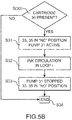
- the pressure Ps can be detected by the sensor 47. This injection can be done periodically.
- the solvent pressure Ps reduces to a value P2 ⁇ P1.
- the solvent can then be reinjected into the main reservoir 10, as was explained above.
- the controller still produces a diagnostic of a blockage situation.
- the pressure P1 is then held for a given duration ⁇ t1, for example a few seconds, to eliminate the obstacle.
- This may be combined with one or several pressure pulses or sudden variations, for example by open and close cycles of solenoid valve 35, to reach a pressure P3>P1, each of these « pulses » being generated for example for a short period, with duration ⁇ t2 ⁇ ⁇ t1. If the pressure Ps reduces after this step to value P2 ⁇ P1, then the obstacle must have been eliminated and solvent can be reinjected into the main reservoir 10, as described above.
- one solution is to perform a manual action and/or to replace the cannula 300 or the ink module itself (that contains some of the fluid connections between the cartridge 30 and the main reservoir).
- the pressurised solvent transferred to the cartridge 30 can then be pumped to the main reservoir 10.
- the circuit is then the circuit normally followed by ink from the cartridge to the main reservoir; after cleaning, the set of valves 33-35 is reconfigured to send cleaning solvent to the main reservoir 10. Therefore the solvent cleans the conduits in which it will circulate and the cannula 300, and is then kept in the circuit without being lost.
- a blocking situation in one of the conduits or the cannula can be detected using the machine controller.
- This controller will:
- the means used for this purpose can be the means described above (tag 30a and controller). It can be checked in advance whether or not the solvent level is sufficient or if it is greater than a lower limiting value. As described above, this step can also be performed when cleaning is done after it has been detected that the cartridge is in the empty state,
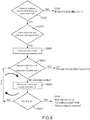
- FIG. 6 An example embodiment of this method is shown in figure 6 .
- a first step (S100) the solvent level in the intermediate reservoir 14 is checked.
- this level is less than a value at a predetermined threshold, then the printer is stopped immediately so that it will not operate without solvent. This step may also be performed in the case of cleaning after it is detected that the cartridge is in the empty state.
- the solvent may be pressurised (step S200), for example to a pressure P1 between 1 bar and 10 bars, or between 1 bar and 5 bars. If this pressure cannot be reached, then a defect is detected. If this pressure can be achieved, the solvent is transferred (step S300) towards the ink cartridge 30 as described above, by opening valve 33. More specifically, valve 35 remains in position « 32 » (« NO »), solvent passes through valve 33 (in position « 21 » NC), and opening cycles are then implemented on valve 33 to generate pressure pulses.
- the next step (step S400) is to perform a test on whether the solvent pressure is maintained or reduced during a given duration ⁇ t1. For example, it can be tested if the pressure at the end of this duration has reduced by a predetermined value, for example between 1%xP1 and 50%xP1 or if the solvent level or volume has reduced by a predetermined value ⁇ h1 or ⁇ V1 (for example by measuring solvent in the reservoir 14); if the answer to either of these questions is positive, then it is considered that the circuit is unblocked and the standard operating sequence of the machine can be resumed.
- a predetermined value for example between 1%xP1 and 50%xP1 or if the solvent level or volume has reduced by a predetermined value ⁇ h1 or ⁇ V1
- step S500 the pressure can be temporarily increased (step S500), for example by pressure pulses (or pressure variations) (as described above) that can be generated by one or several open and close cycles of valve 33.
- a test can also be performed on the duration of cleaning or unblocking operations (step S600); if the cycle duration is longer than a predetermined duration ⁇ t, it may be decided to stop cleaning and for example to replace the ink module. Otherwise, the test in the previous step S400 can be repeated until the predetermined duration has been reached.
- the diagnostic concerning a blockage situation and the remedy provided for it can be formulated and triggered by the machine itself, without any action by an operator, and without the machine being stopped.
- the machine can continue to print at the same time.
- Figure 7 shows an in ink circuit in which the circuit and the method described above, particularly with reference to figures 3 , 5A , 5B or 6 , can be used.
- the print head 1 At the outlet from the main reservoir 10, there is a filter 22, and then the pump 20 and an anti-pulse device 23. As described above, ink is transferred to the print head 1 through the conduit 21 connected on the downstream side of the anti-pulse device 23, between the pump 20 and the valve 37.
- the print head itself contains a valve that enables or disables production of an ink jet and possibly printing.
- Ink is filtered by the main filter 27 before being sent to the head 1.
- a pressure and possibly temperature sensor 24 may be provided as shown in the figure; data output by this sensor are used by the controller to slave the ink pressure to a set value, usually when the velocity of the ink jet in the head is not available (for example when ejection of the jet is stopped, or when the jet velocity cannot be measured).
- the intermediate reservoir 14 forms a storage reservoir inside which solvent is stored.
- This reservoir is intermediate between the solvent cartridge 40 (removable) and the reservoir 10.
- Solvent can be sent from the cartridge 40 to this reservoir 14 as described below.
- a conduit 141 can be used to bring the free volume located above each of the liquids contained in the reservoirs 10 and 14 to the same atmospheric pressure.
- a solvent transfer pump 41 transfers solvent towards the ink circuit, as described above.
- This solvent passes through a 3-way valve 42, which can therefore direct it either to the ink circuit ( « NC » position of valve 42), or to the print head 1 ( « NO » position of valve 42).
- a restriction 45 at the inlet to the reservoir 14 enables filing of the reservoir and participates in pressure generation.
- the reservoir 14 can be filled as follows: the valve 39 is in the « NC » position (see figure 6 ), so that solvent can be pumped using pump 41, from the cartridge 40.
- the valve 42 is in the closed (NC) position while valve 35 is in the NC position, which blocks circulation of solvent towards the cartridge 30 and also towards the conduit 343; therefore, solvent is directed towards the restriction 45 and enters the intermediate reservoir 14.
- the reference 50 refers to a conduit through which ink and/or solvent from the print head gutter or from the head rinsing circuit can be transferred to the main reservoir 10.
- the level measurement can be used to estimate whether or not a cartridge 30 is empty, as described above.
- the invention is particularly useful for ink containing dense particle dispersions such as metals or metal oxide pigments, for example titanium, zinc, chromium, cobalt or Iron (such as TiO 2 , ZnO, Fe 2 O 3 , Fe 3 O 4 , etc.) in the form of micronic or sub-micronic particles.
- dense particle dispersions such as metals or metal oxide pigments, for example titanium, zinc, chromium, cobalt or Iron (such as TiO 2 , ZnO, Fe 2 O 3 , Fe 3 O 4 , etc.) in the form of micronic or sub-micronic particles.
- Such a pigment ink can for example be based on TiO 2 , and can be used for marking and identification of black or dark supports.
- a system for mixing ink from the cartridge, comprising:
- a fastening screw can be used to fix the magnet support 73 onto the motor 71.
- a magnetised bar 75 is inserted inside the ink cartridge 30. Interaction of these elements can rotate the magnet 75 inside the ink and thus stir ink in the cartridge.
Applications Claiming Priority (2)
| Application Number | Priority Date | Filing Date | Title |
|---|---|---|---|
| FR1552875A FR3034346A1 (fr) | 2015-04-02 | 2015-04-02 | Procede et dispositif d'entretien et de protection d'une connexion hydraulique |
| FR1554355A FR3034347B1 (fr) | 2015-04-02 | 2015-05-13 | Procede et dispositif d'entretien et de protection d'une connexion hydraulique |
Publications (2)
| Publication Number | Publication Date |
|---|---|
| EP3085541A1 true EP3085541A1 (fr) | 2016-10-26 |
| EP3085541B1 EP3085541B1 (fr) | 2018-09-12 |
Family
ID=55587215
Family Applications (1)
| Application Number | Title | Priority Date | Filing Date |
|---|---|---|---|
| EP16163331.8A Active EP3085541B1 (fr) | 2015-04-02 | 2016-03-31 | Procédé et dispositif pour la maintenance et la protection d'une liaison hydraulique |
Country Status (1)
| Country | Link |
|---|---|
| EP (1) | EP3085541B1 (fr) |
Cited By (4)
| Publication number | Priority date | Publication date | Assignee | Title |
|---|---|---|---|---|
| CN109649013A (zh) * | 2018-12-21 | 2019-04-19 | 上海华炙电子设备有限公司 | 喷码机墨水系统及墨水喷码机耗材添加方法 |
| EP4023445A1 (fr) | 2020-12-30 | 2022-07-06 | Dover Europe Sàrl | Circuit d'encre comportant plusieurs unités modulaires |
| EP4023444A1 (fr) | 2020-12-30 | 2022-07-06 | Dover Europe Sàrl | Procédé de nettoyage pour le circuit hydraulique d'une imprimante à jet d'encre |
| CN116100955A (zh) * | 2023-03-22 | 2023-05-12 | 广州市普理司科技有限公司 | 数码印刷机墨路控制系统 |
Citations (5)
| Publication number | Priority date | Publication date | Assignee | Title |
|---|---|---|---|---|
| FR2618728A1 (fr) * | 1987-07-31 | 1989-02-03 | Ricard Claude | Procede pour eviter le bouchage de la buse d'injection d'encre d'une imprimante a jet d'encre et imprimantes mettant en oeuvre ce procede |
| WO2002096654A1 (fr) * | 2001-05-30 | 2002-12-05 | 3M Innovative Properties Company | Imprimante a jet d'encre utilisant de l'encre pigmentee |
| US20100079517A1 (en) * | 2008-09-30 | 2010-04-01 | Seiko Epson Corporation | Liquid ejecting apparatus |
| FR2954215A1 (fr) * | 2009-12-23 | 2011-06-24 | Markem Imaje | Systeme de determination de l'autonomie en fluides consommables d'une imprimante a jet d'encre continu |
| US20130242005A1 (en) * | 2011-09-14 | 2013-09-19 | Seiko Epson Corporation | Liquid ejecting apparatus and liquid transfer method |
-
2016
- 2016-03-31 EP EP16163331.8A patent/EP3085541B1/fr active Active
Patent Citations (5)
| Publication number | Priority date | Publication date | Assignee | Title |
|---|---|---|---|---|
| FR2618728A1 (fr) * | 1987-07-31 | 1989-02-03 | Ricard Claude | Procede pour eviter le bouchage de la buse d'injection d'encre d'une imprimante a jet d'encre et imprimantes mettant en oeuvre ce procede |
| WO2002096654A1 (fr) * | 2001-05-30 | 2002-12-05 | 3M Innovative Properties Company | Imprimante a jet d'encre utilisant de l'encre pigmentee |
| US20100079517A1 (en) * | 2008-09-30 | 2010-04-01 | Seiko Epson Corporation | Liquid ejecting apparatus |
| FR2954215A1 (fr) * | 2009-12-23 | 2011-06-24 | Markem Imaje | Systeme de determination de l'autonomie en fluides consommables d'une imprimante a jet d'encre continu |
| US20130242005A1 (en) * | 2011-09-14 | 2013-09-19 | Seiko Epson Corporation | Liquid ejecting apparatus and liquid transfer method |
Cited By (5)
| Publication number | Priority date | Publication date | Assignee | Title |
|---|---|---|---|---|
| CN109649013A (zh) * | 2018-12-21 | 2019-04-19 | 上海华炙电子设备有限公司 | 喷码机墨水系统及墨水喷码机耗材添加方法 |
| EP4023445A1 (fr) | 2020-12-30 | 2022-07-06 | Dover Europe Sàrl | Circuit d'encre comportant plusieurs unités modulaires |
| EP4023444A1 (fr) | 2020-12-30 | 2022-07-06 | Dover Europe Sàrl | Procédé de nettoyage pour le circuit hydraulique d'une imprimante à jet d'encre |
| CN116100955A (zh) * | 2023-03-22 | 2023-05-12 | 广州市普理司科技有限公司 | 数码印刷机墨路控制系统 |
| CN116100955B (zh) * | 2023-03-22 | 2023-10-31 | 广州市普理司科技有限公司 | 数码印刷机墨路控制系统 |
Also Published As
| Publication number | Publication date |
|---|---|
| EP3085541B1 (fr) | 2018-09-12 |
Similar Documents
| Publication | Publication Date | Title |
|---|---|---|
| US9701129B2 (en) | Method and device for maintenance and protection of a hydraulic connection | |
| EP3093144B1 (fr) | Procédé et dispositif de maintenance partielle d'un circuit hydraulique | |
| EP3085541B1 (fr) | Procédé et dispositif pour la maintenance et la protection d'une liaison hydraulique | |
| US10647122B2 (en) | Method and device for managing ink quality in an inkjet printer | |
| WO2005108096A1 (fr) | Procede d'arret de la tete d'imprimante a jet d'encre | |
| JP2023184704A (ja) | インクジェット記録装置 | |
| US9895898B2 (en) | Lid for an ink reservoir with mixing function | |
| EP1405726B1 (fr) | Démarrage automatique d'un systeme d'impression à l'encre à base de solvent | |
| US10543694B2 (en) | Method and device for cleaning and protecting a hydraulic connection | |
| US10189268B2 (en) | Solvent or ink container plug | |
| JP2003191498A (ja) | インクジェット記録装置、インクジェット記録装置の制御回路およびインクジェット記録装置の制御方法 | |
| JP2007190724A (ja) | インクジェット記録装置 | |
| US10688797B2 (en) | Agitating ink in a cartridge | |
| US20240051304A1 (en) | Apparatus and method for printing | |
| CN111483229A (zh) | 油墨喷出装置及油墨喷出方法 | |
| JP2012171180A (ja) | 液体吐出装置 | |
| JP2812628B2 (ja) | インクジェット記録装置のノズル詰り防止装置 |
Legal Events
| Date | Code | Title | Description |
|---|---|---|---|
| PUAI | Public reference made under article 153(3) epc to a published international application that has entered the european phase |
Free format text: ORIGINAL CODE: 0009012 |
|
| AK | Designated contracting states |
Kind code of ref document: A1 Designated state(s): AL AT BE BG CH CY CZ DE DK EE ES FI FR GB GR HR HU IE IS IT LI LT LU LV MC MK MT NL NO PL PT RO RS SE SI SK SM TR |
|
| AX | Request for extension of the european patent |
Extension state: BA ME |
|
| STAA | Information on the status of an ep patent application or granted ep patent |
Free format text: STATUS: REQUEST FOR EXAMINATION WAS MADE |
|
| 17P | Request for examination filed |
Effective date: 20170119 |
|
| RBV | Designated contracting states (corrected) |
Designated state(s): AL AT BE BG CH CY CZ DE DK EE ES FI FR GB GR HR HU IE IS IT LI LT LU LV MC MK MT NL NO PL PT RO RS SE SI SK SM TR |
|
| GRAP | Despatch of communication of intention to grant a patent |
Free format text: ORIGINAL CODE: EPIDOSNIGR1 |
|
| STAA | Information on the status of an ep patent application or granted ep patent |
Free format text: STATUS: GRANT OF PATENT IS INTENDED |
|
| INTG | Intention to grant announced |
Effective date: 20180202 |
|
| GRAS | Grant fee paid |
Free format text: ORIGINAL CODE: EPIDOSNIGR3 |
|
| GRAJ | Information related to disapproval of communication of intention to grant by the applicant or resumption of examination proceedings by the epo deleted |
Free format text: ORIGINAL CODE: EPIDOSDIGR1 |
|
| GRAL | Information related to payment of fee for publishing/printing deleted |
Free format text: ORIGINAL CODE: EPIDOSDIGR3 |
|
| STAA | Information on the status of an ep patent application or granted ep patent |
Free format text: STATUS: REQUEST FOR EXAMINATION WAS MADE |
|
| GRAP | Despatch of communication of intention to grant a patent |
Free format text: ORIGINAL CODE: EPIDOSNIGR1 |
|
| STAA | Information on the status of an ep patent application or granted ep patent |
Free format text: STATUS: GRANT OF PATENT IS INTENDED |
|
| INTC | Intention to grant announced (deleted) | ||
| INTG | Intention to grant announced |
Effective date: 20180704 |
|
| GRAA | (expected) grant |
Free format text: ORIGINAL CODE: 0009210 |
|
| STAA | Information on the status of an ep patent application or granted ep patent |
Free format text: STATUS: THE PATENT HAS BEEN GRANTED |
|
| AK | Designated contracting states |
Kind code of ref document: B1 Designated state(s): AL AT BE BG CH CY CZ DE DK EE ES FI FR GB GR HR HU IE IS IT LI LT LU LV MC MK MT NL NO PL PT RO RS SE SI SK SM TR |
|
| REG | Reference to a national code |
Ref country code: GB Ref legal event code: FG4D |
|
| REG | Reference to a national code |
Ref country code: CH Ref legal event code: EP |
|
| REG | Reference to a national code |
Ref country code: IE Ref legal event code: FG4D |
|
| REG | Reference to a national code |
Ref country code: DE Ref legal event code: R096 Ref document number: 602016005433 Country of ref document: DE |
|
| REG | Reference to a national code |
Ref country code: AT Ref legal event code: REF Ref document number: 1040089 Country of ref document: AT Kind code of ref document: T Effective date: 20181015 |
|
| REG | Reference to a national code |
Ref country code: NL Ref legal event code: MP Effective date: 20180912 |
|
| REG | Reference to a national code |
Ref country code: LT Ref legal event code: MG4D |
|
| PG25 | Lapsed in a contracting state [announced via postgrant information from national office to epo] |
Ref country code: FI Free format text: LAPSE BECAUSE OF FAILURE TO SUBMIT A TRANSLATION OF THE DESCRIPTION OR TO PAY THE FEE WITHIN THE PRESCRIBED TIME-LIMIT Effective date: 20180912 Ref country code: LT Free format text: LAPSE BECAUSE OF FAILURE TO SUBMIT A TRANSLATION OF THE DESCRIPTION OR TO PAY THE FEE WITHIN THE PRESCRIBED TIME-LIMIT Effective date: 20180912 Ref country code: NO Free format text: LAPSE BECAUSE OF FAILURE TO SUBMIT A TRANSLATION OF THE DESCRIPTION OR TO PAY THE FEE WITHIN THE PRESCRIBED TIME-LIMIT Effective date: 20181212 Ref country code: GR Free format text: LAPSE BECAUSE OF FAILURE TO SUBMIT A TRANSLATION OF THE DESCRIPTION OR TO PAY THE FEE WITHIN THE PRESCRIBED TIME-LIMIT Effective date: 20181213 Ref country code: BG Free format text: LAPSE BECAUSE OF FAILURE TO SUBMIT A TRANSLATION OF THE DESCRIPTION OR TO PAY THE FEE WITHIN THE PRESCRIBED TIME-LIMIT Effective date: 20181212 Ref country code: SE Free format text: LAPSE BECAUSE OF FAILURE TO SUBMIT A TRANSLATION OF THE DESCRIPTION OR TO PAY THE FEE WITHIN THE PRESCRIBED TIME-LIMIT Effective date: 20180912 Ref country code: RS Free format text: LAPSE BECAUSE OF FAILURE TO SUBMIT A TRANSLATION OF THE DESCRIPTION OR TO PAY THE FEE WITHIN THE PRESCRIBED TIME-LIMIT Effective date: 20180912 |
|
| PG25 | Lapsed in a contracting state [announced via postgrant information from national office to epo] |
Ref country code: HR Free format text: LAPSE BECAUSE OF FAILURE TO SUBMIT A TRANSLATION OF THE DESCRIPTION OR TO PAY THE FEE WITHIN THE PRESCRIBED TIME-LIMIT Effective date: 20180912 Ref country code: LV Free format text: LAPSE BECAUSE OF FAILURE TO SUBMIT A TRANSLATION OF THE DESCRIPTION OR TO PAY THE FEE WITHIN THE PRESCRIBED TIME-LIMIT Effective date: 20180912 Ref country code: AL Free format text: LAPSE BECAUSE OF FAILURE TO SUBMIT A TRANSLATION OF THE DESCRIPTION OR TO PAY THE FEE WITHIN THE PRESCRIBED TIME-LIMIT Effective date: 20180912 |
|
| REG | Reference to a national code |
Ref country code: AT Ref legal event code: MK05 Ref document number: 1040089 Country of ref document: AT Kind code of ref document: T Effective date: 20180912 |
|
| PG25 | Lapsed in a contracting state [announced via postgrant information from national office to epo] |
Ref country code: ES Free format text: LAPSE BECAUSE OF FAILURE TO SUBMIT A TRANSLATION OF THE DESCRIPTION OR TO PAY THE FEE WITHIN THE PRESCRIBED TIME-LIMIT Effective date: 20180912 Ref country code: CZ Free format text: LAPSE BECAUSE OF FAILURE TO SUBMIT A TRANSLATION OF THE DESCRIPTION OR TO PAY THE FEE WITHIN THE PRESCRIBED TIME-LIMIT Effective date: 20180912 Ref country code: AT Free format text: LAPSE BECAUSE OF FAILURE TO SUBMIT A TRANSLATION OF THE DESCRIPTION OR TO PAY THE FEE WITHIN THE PRESCRIBED TIME-LIMIT Effective date: 20180912 Ref country code: IT Free format text: LAPSE BECAUSE OF FAILURE TO SUBMIT A TRANSLATION OF THE DESCRIPTION OR TO PAY THE FEE WITHIN THE PRESCRIBED TIME-LIMIT Effective date: 20180912 Ref country code: EE Free format text: LAPSE BECAUSE OF FAILURE TO SUBMIT A TRANSLATION OF THE DESCRIPTION OR TO PAY THE FEE WITHIN THE PRESCRIBED TIME-LIMIT Effective date: 20180912 Ref country code: RO Free format text: LAPSE BECAUSE OF FAILURE TO SUBMIT A TRANSLATION OF THE DESCRIPTION OR TO PAY THE FEE WITHIN THE PRESCRIBED TIME-LIMIT Effective date: 20180912 Ref country code: NL Free format text: LAPSE BECAUSE OF FAILURE TO SUBMIT A TRANSLATION OF THE DESCRIPTION OR TO PAY THE FEE WITHIN THE PRESCRIBED TIME-LIMIT Effective date: 20180912 Ref country code: PL Free format text: LAPSE BECAUSE OF FAILURE TO SUBMIT A TRANSLATION OF THE DESCRIPTION OR TO PAY THE FEE WITHIN THE PRESCRIBED TIME-LIMIT Effective date: 20180912 Ref country code: IS Free format text: LAPSE BECAUSE OF FAILURE TO SUBMIT A TRANSLATION OF THE DESCRIPTION OR TO PAY THE FEE WITHIN THE PRESCRIBED TIME-LIMIT Effective date: 20190112 |
|
| PG25 | Lapsed in a contracting state [announced via postgrant information from national office to epo] |
Ref country code: PT Free format text: LAPSE BECAUSE OF FAILURE TO SUBMIT A TRANSLATION OF THE DESCRIPTION OR TO PAY THE FEE WITHIN THE PRESCRIBED TIME-LIMIT Effective date: 20190112 Ref country code: SK Free format text: LAPSE BECAUSE OF FAILURE TO SUBMIT A TRANSLATION OF THE DESCRIPTION OR TO PAY THE FEE WITHIN THE PRESCRIBED TIME-LIMIT Effective date: 20180912 Ref country code: SM Free format text: LAPSE BECAUSE OF FAILURE TO SUBMIT A TRANSLATION OF THE DESCRIPTION OR TO PAY THE FEE WITHIN THE PRESCRIBED TIME-LIMIT Effective date: 20180912 |
|
| REG | Reference to a national code |
Ref country code: DE Ref legal event code: R097 Ref document number: 602016005433 Country of ref document: DE |
|
| PLBE | No opposition filed within time limit |
Free format text: ORIGINAL CODE: 0009261 |
|
| STAA | Information on the status of an ep patent application or granted ep patent |
Free format text: STATUS: NO OPPOSITION FILED WITHIN TIME LIMIT |
|
| PG25 | Lapsed in a contracting state [announced via postgrant information from national office to epo] |
Ref country code: DK Free format text: LAPSE BECAUSE OF FAILURE TO SUBMIT A TRANSLATION OF THE DESCRIPTION OR TO PAY THE FEE WITHIN THE PRESCRIBED TIME-LIMIT Effective date: 20180912 |
|
| 26N | No opposition filed |
Effective date: 20190613 |
|
| PG25 | Lapsed in a contracting state [announced via postgrant information from national office to epo] |
Ref country code: SI Free format text: LAPSE BECAUSE OF FAILURE TO SUBMIT A TRANSLATION OF THE DESCRIPTION OR TO PAY THE FEE WITHIN THE PRESCRIBED TIME-LIMIT Effective date: 20180912 |
|
| PG25 | Lapsed in a contracting state [announced via postgrant information from national office to epo] |
Ref country code: MC Free format text: LAPSE BECAUSE OF FAILURE TO SUBMIT A TRANSLATION OF THE DESCRIPTION OR TO PAY THE FEE WITHIN THE PRESCRIBED TIME-LIMIT Effective date: 20180912 |
|
| REG | Reference to a national code |
Ref country code: CH Ref legal event code: PL |
|
| PG25 | Lapsed in a contracting state [announced via postgrant information from national office to epo] |
Ref country code: LU Free format text: LAPSE BECAUSE OF NON-PAYMENT OF DUE FEES Effective date: 20190331 |
|
| REG | Reference to a national code |
Ref country code: BE Ref legal event code: MM Effective date: 20190331 |
|
| PG25 | Lapsed in a contracting state [announced via postgrant information from national office to epo] |
Ref country code: LI Free format text: LAPSE BECAUSE OF NON-PAYMENT OF DUE FEES Effective date: 20190331 Ref country code: CH Free format text: LAPSE BECAUSE OF NON-PAYMENT OF DUE FEES Effective date: 20190331 Ref country code: IE Free format text: LAPSE BECAUSE OF NON-PAYMENT OF DUE FEES Effective date: 20190331 |
|
| PG25 | Lapsed in a contracting state [announced via postgrant information from national office to epo] |
Ref country code: BE Free format text: LAPSE BECAUSE OF NON-PAYMENT OF DUE FEES Effective date: 20190331 |
|
| PG25 | Lapsed in a contracting state [announced via postgrant information from national office to epo] |
Ref country code: TR Free format text: LAPSE BECAUSE OF FAILURE TO SUBMIT A TRANSLATION OF THE DESCRIPTION OR TO PAY THE FEE WITHIN THE PRESCRIBED TIME-LIMIT Effective date: 20180912 |
|
| PG25 | Lapsed in a contracting state [announced via postgrant information from national office to epo] |
Ref country code: MT Free format text: LAPSE BECAUSE OF NON-PAYMENT OF DUE FEES Effective date: 20190331 |
|
| PG25 | Lapsed in a contracting state [announced via postgrant information from national office to epo] |
Ref country code: CY Free format text: LAPSE BECAUSE OF FAILURE TO SUBMIT A TRANSLATION OF THE DESCRIPTION OR TO PAY THE FEE WITHIN THE PRESCRIBED TIME-LIMIT Effective date: 20180912 |
|
| PG25 | Lapsed in a contracting state [announced via postgrant information from national office to epo] |
Ref country code: HU Free format text: LAPSE BECAUSE OF FAILURE TO SUBMIT A TRANSLATION OF THE DESCRIPTION OR TO PAY THE FEE WITHIN THE PRESCRIBED TIME-LIMIT; INVALID AB INITIO Effective date: 20160331 |
|
| PG25 | Lapsed in a contracting state [announced via postgrant information from national office to epo] |
Ref country code: MK Free format text: LAPSE BECAUSE OF FAILURE TO SUBMIT A TRANSLATION OF THE DESCRIPTION OR TO PAY THE FEE WITHIN THE PRESCRIBED TIME-LIMIT Effective date: 20180912 |
|
| PGFP | Annual fee paid to national office [announced via postgrant information from national office to epo] |
Ref country code: FR Payment date: 20230323 Year of fee payment: 8 |
|
| PGFP | Annual fee paid to national office [announced via postgrant information from national office to epo] |
Ref country code: GB Payment date: 20230321 Year of fee payment: 8 Ref country code: DE Payment date: 20230328 Year of fee payment: 8 |
|
| P01 | Opt-out of the competence of the unified patent court (upc) registered |
Effective date: 20230530 |
|
| PGFP | Annual fee paid to national office [announced via postgrant information from national office to epo] |
Ref country code: DE Payment date: 20240328 Year of fee payment: 9 Ref country code: GB Payment date: 20240319 Year of fee payment: 9 |