EP3085513A1 - Device for manufacturing uneven-thickness film, and method for manufacturing uneven-thickness film - Google Patents
Device for manufacturing uneven-thickness film, and method for manufacturing uneven-thickness film Download PDFInfo
- Publication number
- EP3085513A1 EP3085513A1 EP14871003.1A EP14871003A EP3085513A1 EP 3085513 A1 EP3085513 A1 EP 3085513A1 EP 14871003 A EP14871003 A EP 14871003A EP 3085513 A1 EP3085513 A1 EP 3085513A1
- Authority
- EP
- European Patent Office
- Prior art keywords
- roller
- shaped portion
- truncated
- cone
- diameter
- Prior art date
- Legal status (The legal status is an assumption and is not a legal conclusion. Google has not performed a legal analysis and makes no representation as to the accuracy of the status listed.)
- Granted
Links
Images


Classifications
-
- B—PERFORMING OPERATIONS; TRANSPORTING
- B29—WORKING OF PLASTICS; WORKING OF SUBSTANCES IN A PLASTIC STATE IN GENERAL
- B29C—SHAPING OR JOINING OF PLASTICS; SHAPING OF MATERIAL IN A PLASTIC STATE, NOT OTHERWISE PROVIDED FOR; AFTER-TREATMENT OF THE SHAPED PRODUCTS, e.g. REPAIRING
- B29C43/00—Compression moulding, i.e. applying external pressure to flow the moulding material; Apparatus therefor
- B29C43/32—Component parts, details or accessories; Auxiliary operations
- B29C43/44—Compression means for making articles of indefinite length
- B29C43/46—Rollers
-
- B—PERFORMING OPERATIONS; TRANSPORTING
- B29—WORKING OF PLASTICS; WORKING OF SUBSTANCES IN A PLASTIC STATE IN GENERAL
- B29C—SHAPING OR JOINING OF PLASTICS; SHAPING OF MATERIAL IN A PLASTIC STATE, NOT OTHERWISE PROVIDED FOR; AFTER-TREATMENT OF THE SHAPED PRODUCTS, e.g. REPAIRING
- B29C43/00—Compression moulding, i.e. applying external pressure to flow the moulding material; Apparatus therefor
- B29C43/22—Compression moulding, i.e. applying external pressure to flow the moulding material; Apparatus therefor of articles of indefinite length
- B29C43/222—Compression moulding, i.e. applying external pressure to flow the moulding material; Apparatus therefor of articles of indefinite length characterised by the shape of the surface
-
- B—PERFORMING OPERATIONS; TRANSPORTING
- B29—WORKING OF PLASTICS; WORKING OF SUBSTANCES IN A PLASTIC STATE IN GENERAL
- B29C—SHAPING OR JOINING OF PLASTICS; SHAPING OF MATERIAL IN A PLASTIC STATE, NOT OTHERWISE PROVIDED FOR; AFTER-TREATMENT OF THE SHAPED PRODUCTS, e.g. REPAIRING
- B29C48/00—Extrusion moulding, i.e. expressing the moulding material through a die or nozzle which imparts the desired form; Apparatus therefor
- B29C48/001—Combinations of extrusion moulding with other shaping operations
- B29C48/0011—Combinations of extrusion moulding with other shaping operations combined with compression moulding
-
- B—PERFORMING OPERATIONS; TRANSPORTING
- B29—WORKING OF PLASTICS; WORKING OF SUBSTANCES IN A PLASTIC STATE IN GENERAL
- B29C—SHAPING OR JOINING OF PLASTICS; SHAPING OF MATERIAL IN A PLASTIC STATE, NOT OTHERWISE PROVIDED FOR; AFTER-TREATMENT OF THE SHAPED PRODUCTS, e.g. REPAIRING
- B29C48/00—Extrusion moulding, i.e. expressing the moulding material through a die or nozzle which imparts the desired form; Apparatus therefor
- B29C48/03—Extrusion moulding, i.e. expressing the moulding material through a die or nozzle which imparts the desired form; Apparatus therefor characterised by the shape of the extruded material at extrusion
- B29C48/07—Flat, e.g. panels
- B29C48/08—Flat, e.g. panels flexible, e.g. films
-
- B—PERFORMING OPERATIONS; TRANSPORTING
- B29—WORKING OF PLASTICS; WORKING OF SUBSTANCES IN A PLASTIC STATE IN GENERAL
- B29C—SHAPING OR JOINING OF PLASTICS; SHAPING OF MATERIAL IN A PLASTIC STATE, NOT OTHERWISE PROVIDED FOR; AFTER-TREATMENT OF THE SHAPED PRODUCTS, e.g. REPAIRING
- B29C48/00—Extrusion moulding, i.e. expressing the moulding material through a die or nozzle which imparts the desired form; Apparatus therefor
- B29C48/03—Extrusion moulding, i.e. expressing the moulding material through a die or nozzle which imparts the desired form; Apparatus therefor characterised by the shape of the extruded material at extrusion
- B29C48/12—Articles with an irregular circumference when viewed in cross-section, e.g. window profiles
-
- B—PERFORMING OPERATIONS; TRANSPORTING
- B29—WORKING OF PLASTICS; WORKING OF SUBSTANCES IN A PLASTIC STATE IN GENERAL
- B29D—PRODUCING PARTICULAR ARTICLES FROM PLASTICS OR FROM SUBSTANCES IN A PLASTIC STATE
- B29D11/00—Producing optical elements, e.g. lenses or prisms
- B29D11/00663—Production of light guides
-
- G—PHYSICS
- G02—OPTICS
- G02B—OPTICAL ELEMENTS, SYSTEMS OR APPARATUS
- G02B6/00—Light guides; Structural details of arrangements comprising light guides and other optical elements, e.g. couplings
- G02B6/0001—Light guides; Structural details of arrangements comprising light guides and other optical elements, e.g. couplings specially adapted for lighting devices or systems
- G02B6/0011—Light guides; Structural details of arrangements comprising light guides and other optical elements, e.g. couplings specially adapted for lighting devices or systems the light guides being planar or of plate-like form
- G02B6/0013—Means for improving the coupling-in of light from the light source into the light guide
- G02B6/0015—Means for improving the coupling-in of light from the light source into the light guide provided on the surface of the light guide or in the bulk of it
- G02B6/002—Means for improving the coupling-in of light from the light source into the light guide provided on the surface of the light guide or in the bulk of it by shaping at least a portion of the light guide, e.g. with collimating, focussing or diverging surfaces
-
- G—PHYSICS
- G02—OPTICS
- G02B—OPTICAL ELEMENTS, SYSTEMS OR APPARATUS
- G02B6/00—Light guides; Structural details of arrangements comprising light guides and other optical elements, e.g. couplings
- G02B6/0001—Light guides; Structural details of arrangements comprising light guides and other optical elements, e.g. couplings specially adapted for lighting devices or systems
- G02B6/0011—Light guides; Structural details of arrangements comprising light guides and other optical elements, e.g. couplings specially adapted for lighting devices or systems the light guides being planar or of plate-like form
- G02B6/0065—Manufacturing aspects; Material aspects
-
- B—PERFORMING OPERATIONS; TRANSPORTING
- B29—WORKING OF PLASTICS; WORKING OF SUBSTANCES IN A PLASTIC STATE IN GENERAL
- B29C—SHAPING OR JOINING OF PLASTICS; SHAPING OF MATERIAL IN A PLASTIC STATE, NOT OTHERWISE PROVIDED FOR; AFTER-TREATMENT OF THE SHAPED PRODUCTS, e.g. REPAIRING
- B29C43/00—Compression moulding, i.e. applying external pressure to flow the moulding material; Apparatus therefor
- B29C43/32—Component parts, details or accessories; Auxiliary operations
- B29C43/44—Compression means for making articles of indefinite length
- B29C43/46—Rollers
- B29C2043/461—Rollers the rollers having specific surface features
- B29C2043/463—Rollers the rollers having specific surface features corrugated, patterned or embossed surface
-
- B—PERFORMING OPERATIONS; TRANSPORTING
- B29—WORKING OF PLASTICS; WORKING OF SUBSTANCES IN A PLASTIC STATE IN GENERAL
- B29C—SHAPING OR JOINING OF PLASTICS; SHAPING OF MATERIAL IN A PLASTIC STATE, NOT OTHERWISE PROVIDED FOR; AFTER-TREATMENT OF THE SHAPED PRODUCTS, e.g. REPAIRING
- B29C43/00—Compression moulding, i.e. applying external pressure to flow the moulding material; Apparatus therefor
- B29C43/32—Component parts, details or accessories; Auxiliary operations
- B29C43/44—Compression means for making articles of indefinite length
- B29C43/46—Rollers
- B29C2043/466—Rollers the rollers having specific shape, e.g. non cylindrical rollers, conical rollers
-
- B—PERFORMING OPERATIONS; TRANSPORTING
- B29—WORKING OF PLASTICS; WORKING OF SUBSTANCES IN A PLASTIC STATE IN GENERAL
- B29C—SHAPING OR JOINING OF PLASTICS; SHAPING OF MATERIAL IN A PLASTIC STATE, NOT OTHERWISE PROVIDED FOR; AFTER-TREATMENT OF THE SHAPED PRODUCTS, e.g. REPAIRING
- B29C2793/00—Shaping techniques involving a cutting or machining operation
- B29C2793/0063—Cutting longitudinally
-
- B—PERFORMING OPERATIONS; TRANSPORTING
- B29—WORKING OF PLASTICS; WORKING OF SUBSTANCES IN A PLASTIC STATE IN GENERAL
- B29C—SHAPING OR JOINING OF PLASTICS; SHAPING OF MATERIAL IN A PLASTIC STATE, NOT OTHERWISE PROVIDED FOR; AFTER-TREATMENT OF THE SHAPED PRODUCTS, e.g. REPAIRING
- B29C2793/00—Shaping techniques involving a cutting or machining operation
- B29C2793/009—Shaping techniques involving a cutting or machining operation after shaping
-
- B—PERFORMING OPERATIONS; TRANSPORTING
- B29—WORKING OF PLASTICS; WORKING OF SUBSTANCES IN A PLASTIC STATE IN GENERAL
- B29C—SHAPING OR JOINING OF PLASTICS; SHAPING OF MATERIAL IN A PLASTIC STATE, NOT OTHERWISE PROVIDED FOR; AFTER-TREATMENT OF THE SHAPED PRODUCTS, e.g. REPAIRING
- B29C43/00—Compression moulding, i.e. applying external pressure to flow the moulding material; Apparatus therefor
- B29C43/22—Compression moulding, i.e. applying external pressure to flow the moulding material; Apparatus therefor of articles of indefinite length
- B29C43/24—Calendering
-
- B—PERFORMING OPERATIONS; TRANSPORTING
- B29—WORKING OF PLASTICS; WORKING OF SUBSTANCES IN A PLASTIC STATE IN GENERAL
- B29C—SHAPING OR JOINING OF PLASTICS; SHAPING OF MATERIAL IN A PLASTIC STATE, NOT OTHERWISE PROVIDED FOR; AFTER-TREATMENT OF THE SHAPED PRODUCTS, e.g. REPAIRING
- B29C48/00—Extrusion moulding, i.e. expressing the moulding material through a die or nozzle which imparts the desired form; Apparatus therefor
- B29C48/25—Component parts, details or accessories; Auxiliary operations
- B29C48/88—Thermal treatment of the stream of extruded material, e.g. cooling
- B29C48/911—Cooling
- B29C48/9135—Cooling of flat articles, e.g. using specially adapted supporting means
- B29C48/914—Cooling drums
-
- B—PERFORMING OPERATIONS; TRANSPORTING
- B29—WORKING OF PLASTICS; WORKING OF SUBSTANCES IN A PLASTIC STATE IN GENERAL
- B29K—INDEXING SCHEME ASSOCIATED WITH SUBCLASSES B29B, B29C OR B29D, RELATING TO MOULDING MATERIALS OR TO MATERIALS FOR MOULDS, REINFORCEMENTS, FILLERS OR PREFORMED PARTS, e.g. INSERTS
- B29K2033/00—Use of polymers of unsaturated acids or derivatives thereof as moulding material
-
- B—PERFORMING OPERATIONS; TRANSPORTING
- B29—WORKING OF PLASTICS; WORKING OF SUBSTANCES IN A PLASTIC STATE IN GENERAL
- B29K—INDEXING SCHEME ASSOCIATED WITH SUBCLASSES B29B, B29C OR B29D, RELATING TO MOULDING MATERIALS OR TO MATERIALS FOR MOULDS, REINFORCEMENTS, FILLERS OR PREFORMED PARTS, e.g. INSERTS
- B29K2069/00—Use of PC, i.e. polycarbonates or derivatives thereof, as moulding material
-
- B—PERFORMING OPERATIONS; TRANSPORTING
- B29—WORKING OF PLASTICS; WORKING OF SUBSTANCES IN A PLASTIC STATE IN GENERAL
- B29K—INDEXING SCHEME ASSOCIATED WITH SUBCLASSES B29B, B29C OR B29D, RELATING TO MOULDING MATERIALS OR TO MATERIALS FOR MOULDS, REINFORCEMENTS, FILLERS OR PREFORMED PARTS, e.g. INSERTS
- B29K2995/00—Properties of moulding materials, reinforcements, fillers, preformed parts or moulds
- B29K2995/0018—Properties of moulding materials, reinforcements, fillers, preformed parts or moulds having particular optical properties, e.g. fluorescent or phosphorescent
- B29K2995/0026—Transparent
-
- B—PERFORMING OPERATIONS; TRANSPORTING
- B29—WORKING OF PLASTICS; WORKING OF SUBSTANCES IN A PLASTIC STATE IN GENERAL
- B29L—INDEXING SCHEME ASSOCIATED WITH SUBCLASS B29C, RELATING TO PARTICULAR ARTICLES
- B29L2011/00—Optical elements, e.g. lenses, prisms
- B29L2011/0075—Light guides, optical cables
Definitions
- the present invention relates to a device and a method for manufacturing an uneven-thickness film made of a synthetic resin, for example, an uneven-thickness film used as a light guide plate for a back irradiating device of a liquid crystal display device.
- a liquid crystal display device such as a tablet PC, a smartphone or the like employs a light guide plate (light guide film) of an edge light type as a back lighting device.
- An edge-light-type light guide plate emits light incident on one edge (light incident surface) of the transparent square plate from its surface (light emitting surface).
- a back lighting device has a light source arranged on at least one edge of the light guide plate.
- the surface opposing the light emitting surface of the light guide plate (light-reflecting surface) comprises an element for changing the advancing angle of the light transmitting the light guide plate (hereinafter, referred to as a "polarizing element").
- the light guide plate comprises a polarizing element whose density distribution and shape is determined such that the brightness of the light is uniform over the entire light emitting surface.
- a method for manufacturing such a light guide plate is generally an injection molding method like the method disclosed in Japanese Unexamined Patent Application Publication No. Heisei 9-222514 .
- a light guide plate manufactured by an injection molding method is restricted in thinning the plate thickness due to limitations in fluidity, moldability and the like, and thus the thinner side of the plate thickness is 0.3-0.4 mm at the thinnest.
- the size of the light guide plate is increased along with the increase in the size of the liquid crystal screens, a larger injection molding machine is necessary, which is associated with problems such as an increase in the manufacturing cost, requirements of excessive pressure, relatively long pressurizing time and cooling time to ensure the transfer accuracy, and the like.
- the shape of the extrusion die port of the extruding device needs to correspond to the shape of the desired uneven-thickness film.
- the uneven-thickness films that are symmetrically arranged side by side need to be cut off from each other, which requires the end face of the cut part to be carefully polished to be used as a light incident surface.
- the present invention was made in light of the above-described circumstances. Specifically, the present invention has an objective of providing a device and a method for manufacturing an uneven-thickness film, which can mold an uneven-thickness film without changing the shape of an extrusion die port of an extruding device from a substantially rectangular shape that is the same as the one used for usual film molding. In addition, the present invention has an objective of providing a device and a method for manufacturing an uneven-thickness film, wherein a light guide film can easily be made only by dividing (cutting) the manufactured uneven-thickness film in a direction substantially vertical to the extruding direction.
- the present invention is constituted as follows.
- a device for manufacturing an uneven-thickness film comprising a first roller and a second roller for molding the uneven-thickness film, wherein: the first roller comprises a column-shaped portion and a disc-shaped portion; the second roller comprises a truncated-cone-shaped portion and a disc-shaped small-diameter portion; and the small-diameter portion gently connects with the truncated-cone-shaped portion on the smaller-diameter face side.
- Aspect 10 The manufacturing device according to Aspect 9, wherein the manufacturing device forms a thick part to the molded body of the uneven-thickness film between the column-shaped portion of the first roller and the truncated-cone-shaped portion of the second roller, and forms a thin connecting portion to the molded body between the disc-shaped portion of the first roller and the small-diameter portion of the second roller.
- Aspect 11 The manufacturing device according to Aspect 9 or 10, wherein portions where the disc-shaped portion of the first roller opposes the small-diameter portion of the second roller are substantially parallel.
- Aspect 12 The manufacturing device according to any one of Aspects 9-11, wherein the truncated-cone-shaped portion is a pair of truncated-cone-shaped portions, and the pair of truncated-cone-shaped portions are symmetrically arranged to sandwich the small-diameter portion.
- Aspect 13 The manufacturing device according to any one of Aspects 9-12, wherein the portions constituting the first roller or the second roller are integrally arranged on the same axis.
- Aspect 14 The manufacturing device according to any one of Aspects 9-13, wherein the small-diameter portion connects with the smaller-diameter face of the truncated-cone-shaped portion.
- Aspect 15 The manufacturing device according to any one of Aspects 9-14, wherein the second roller further comprises a column-shaped portion.
- Aspect 16 The manufacturing device according to Aspect 15, wherein the column-shaped portion of the second roller is connected with the larger-diameter face of the truncated-cone-shaped portion of the second roller.
- Aspect 17 The manufacturing device according to Aspect 2 or 10, wherein the thick part of the molded body is formed such that the film thickness thereof changes from one side part to the other side part that are parallel to the extruding direction.
- Aspect 18 The manufacturing device according to any one of Aspects 1-16, wherein the surface of the truncated-cone-shaped portion comprises a dot pattern.
- Aspect 19 The manufacturing device according to any one of Aspects 1-18, comprising a cutter section for cutting the molded body molded with the first roller and the second roller.
- Aspect 20 The manufacturing device according to any one of Aspects 2, 10 and 17, wherein the molded body of the uneven-thickness film consists of multiple molded sub-bodies which are connected via the connecting portions.
- a method for manufacturing an uneven-thickness film using a first roller and a second roller for molding the uneven-thickness film wherein: the first roller comprises a truncated-cone-shaped portion and a disc-shaped portion; the diameter of the disc-shaped portion is larger than the diameter of the larger-diameter face of the truncated-cone-shaped portion; and the second roller comprises a column-shaped portion, the method comprising the steps of: forming a thick part to the molded body of the uneven-thickness film between the truncated-cone-shaped portion of the first roller and the column-shaped portion of the second roller; and forming a thin connecting portion to the molded body between the disc-shaped portion of the first roller and the column-shaped portion of the second roller.
- a method for manufacturing an uneven-thickness film using a first roller and a second roller for molding the uneven-thickness film wherein: the first roller comprises a column-shaped portion and a disc-shaped portion; the second roller comprises a truncated-cone-shaped portion and a small-diameter portion; and the diameter of the small-diameter portion is smaller than the diameter of the smaller-diameter face of the truncated-cone-shaped portion, the method comprising the steps of: forming a thick part to the molded body of the uneven-thickness film between the column-shaped portion of the first roller and the truncated-cone-shaped portion of the second roller; and forming a thin connecting portion to the molded body between the disc-shaped portion of the first roller and the small-diameter portion of the second roller.
- the connecting portion is formed to have a substantially uniform thickness.
- a device for manufacturing an uneven-thickness film comprising a first roller and a second roller for molding the uneven-thickness film, wherein: (i) the first roller comprises a truncated-cone-shaped portion and a disc-shaped portion, where the diameter of the disc-shaped portion is larger than the diameter of the larger-diameter face of the truncated-cone-shaped portion, and the second roller comprises a column-shaped portion; or (ii) the first roller comprises a column-shaped portion and a disc-shaped portion, and the second roller comprises a truncated-cone-shaped portion and a disc-shaped small-diameter portion, wherein the small-diameter portion gently connects with the truncated-cone-shaped portion on the smaller-diameter face side.
- a method for manufacturing an uneven-thickness film using a first roller and a second roller for molding the uneven-thickness film wherein: (i) the first roller comprises a truncated-cone-shaped portion and a disc-shaped portion, where the diameter of the disc-shaped portion is larger than the diameter of the larger-diameter face of the truncated-cone-shaped portion, and the second roller comprises a column-shaped portion, the method comprising the steps of: forming a thick part to the molded body of the uneven-thickness film between the truncated-cone-shaped portion of the first roller and the column-shaped portion of the second roller; and forming a thin connecting portion to the molded body between the disc-shaped portion of the first roller and the column-shaped portion of the second roller; or (ii) the first roller comprises a column-shaped portion and a disc-shaped portion, and the second roller comprises a truncated-cone-shaped portion and a small-diameter
- the present invention is capable of manufacturing an uneven-thickness film that can easily be divided, continuously with first and second rollers without changing a shape of an extrusion die port.
- Figure 1 is a cross-sectional view of a molded body of an uneven-thickness film extruded by a manufacturing device and a method of a first embodiment, shown in a direction vertical to the extruding (longitudinal) direction.
- the molded body 120 consists of two molded sub-bodies 120'.
- the molded sub-body 120' comprises a flat portion 122 that has a uniform film thickness, an uneven-thickness portion 124 whose film thickness changes, and a connecting portion 128 whose film thickness is thinner than the flat portion 122.
- the connecting portion 128 can be formed to have a substantially uniform film thickness between a disc-shaped portion 232 of a first roller 230 and a column-shaped portion of a second roller 240 which will be described later.
- the top surface of the molded body 120' is formed to rise on the uneven-thickness portion 124 side while the bottom surface of the molded body 120' is formed to be flat.
- the thickness (film thickness) of the uneven-thickness portion 124 decreases from the first side part 126 on the connecting portion 128 side towards the second side part 130 on the flat portion 122 side.
- the side parts 126 of the two uneven-thickness portions 124 oppose to each other via the connecting portion 128.
- the connecting portion 128 is formed on the bottom surface side of the molded bodies 120'.
- Figure 2 is a perspective view showing a molded sub-body 120' obtained by cutting the molded body 120 of the uneven-thickness film shown in Figure 1 .
- the molded sub-body 120' is cut along the cut plane 128a of the connecting portion 128 parallel to the extruding direction, and also cut along two cut planes 132 that is vertical to the extruding direction.
- the two molded sub-bodies 120' are integrally molded to be symmetrically arranged side by side such that the side parts 126 thereof oppose each other as shown in Figure 1 .
- multiple molded bodies including these two molded sub-bodies 120' may integrally be molded to be arranged side by side by connecting the side parts 130 via connecting portions.
- the entire connecting portion 128 is cut off from the molded sub-body 120' to use the resultant as a light guide film.
- the side part 126 serves as a light incident surface
- the side part 130 serves as an end face
- the sloped surface 124a of the uneven-thickness portion 124 serves as a light-reflecting surface
- the upper planar surface of the flat portion 122 serves as a light emitting surface.
- the sloped surface 124a as the light-reflecting surface is formed with a dot pattern that reflects light as will be described later.
- FIG 3 is a part perspective view of a manufacturing device 200 for molding the molded body of the uneven-thickness film shown in Figure 1 .
- the manufacturing device 200 comprises a die 201 for accommodating and extruding a resin, a rectangular-shaped extrusion port 202 formed on the die 201, a first roller 230, a second roller 240 and a third roller 250.
- the first and second rollers 230 and 240 are arranged beneath the extrusion port 202, and arranged to sandwich a pre-molded resin plate 110 extruded from the extrusion port 202.
- the third roller 250 is arranged next to the second roller 240.
- the first roller 230 consists of a disc-shaped portion 232, a pair of truncated-cone-shaped portions 234 that sandwich the disc-shaped portion 232, and a pair of column-shaped portions 236 arranged outside the respective pair of truncated-cone-shaped portions 234.
- the respective portions of the first roller 230 are integrally arranged such that their rotation centers are positioned along the same axis.
- the pair of truncated-cone-shaped portions 234 are symmetrically arranged with respect to the disc-shaped portion 232 with the smaller-diameter faces 234a facing inside and the larger-diameter faces 234b facing outside.
- the diameter of the disc-shaped portion 232 is larger than the diameter of the larger-diameter face 234a of the truncated-cone-shaped portion 234.
- the second roller 240 and the third roller 250 are column-shaped portions as a whole, where the rotation center axis lines of the first to third rollers 230, 240 and 250 are arranged in parallel.
- the portions where the disc-shaped portion 232 of the first roller 230 opposes the column-shaped portion of the second roller 240 are substantially parallel.
- the first roller 230 and the second roller 240 in Figures 3 and 4 may be arranged reversely.
- the entire surface of the truncated-cone-shaped portion 234 comprises a dot pattern 234c, by which a light-reflecting surface is formed on the uneven-thickness portion 124.
- the second roller 240 and third roller 250 have smooth surfaces.
- the manufacturing device 200 heats a resin as a material of a light guide film to a temperature that allows the resin to have a low viscosity with a heating means (not shown), and extrudes this resin as a resin plate 110 from the extrusion port 202 of the die 201.
- the resin plate 110 extruded from the extrusion port 202 is guided to the triple rollers, i.e., the first to third rollers 230, 240 and 250.
- the first and second rollers 230 and 240 shape the resin plate 110 to make a molded body 120.
- the connecting portion 128 is formed between the disc-shaped portion 232 of the first roller 230 and the second roller 240
- the uneven-thickness portion 124 is formed between the truncated-cone-shaped portion 234 of the first roller 230 and the second roller 240
- the flat portion 122 is formed between the column-shaped portion 236 of the first roller 230 and the second roller 240.
- the last third roller 250 is controlled to have a temperature that is lower than the glass-transition temperature of the resin that forms the molded body 120. Accordingly, at least the surface of the molded body 120 is solidified when the molded body 120 leaves the triple rollers.
- the molded body 120 that left the triple rollers continues to advance while being further cooled in the air, is divided in the longitudinal direction at a cutter section (not shown) with a slitter, an edge knife or the like, and is further divided and cut in the plate width direction with a push-cutter or the like, thereby forming a light guide film.
- dots can be formed simultaneously with the molding of the plastic panel (molded body 120).
- dividing in the longitudinal direction may be omitted, in which case the molded body may be split to make light guide films at the stage of assembling the light guide film into a product.
- the disc-shaped portion 232 shown in Figure 4 may be omitted. In this case, the center part of the thickness of the molded body 120 of the uneven-thickness film can be cut to make light guide films.
- Figure 5 is a cross-sectional view of a molded body of an uneven-thickness film extruded by a manufacturing device and a method of the second embodiment, shown in a direction vertical to the extruding direction.
- the molded body 220 consists of two molded sub-bodies 220'.
- the molded sub-body 220' comprises a flat portion 222 that has a uniform film thickness, an uneven-thickness portion 224 whose film thickness changes, and a connecting portion 228 whose film thickness is thinner than the flat portion 222.
- the top surface of the molded body 220' is formed to rise on the uneven-thickness portion 224 side while the bottom surface of the molded body 220' is formed to be flat.
- the thickness (film thickness) of the uneven-thickness portion 224 decreases from the first side part 226 on the connecting portion 228 side towards the second side part 230 on the flat portion 232 side.
- the side parts 126 of the two uneven-thickness portions 224 oppose to each other via the connecting portion 228.
- the connecting portion 228 is formed on the top surface side of the rising molded body 120'.
- the connecting portion 228 can be formed to have a substantially uniform film thickness between a disc-shaped portion 332 of the first roller 330 and a small-diameter portion 342 of the second roller 340 which will be described later.
- Figure 6 is a perspective view showing the molded sub-body 220' obtained by cutting the molded body 220 of the uneven-thickness film shown in Figure 5 .
- the molded sub-bodies 220' are cut along a cut plane 228a of the connecting portion 228 that is parallel to the extruding direction, and also cut along two cut planes 232 that are vertical to the extruding direction.
- the two molded sub-bodies 220' are integrally molded to be symmetrically arranged side by side such that the side parts 226 thereof oppose each other as shown in Figure 5 .
- multiple molded bodies including these two molded sub-bodies 220' may integrally be molded to be arranged side by side by connecting the side parts 230 via connecting portions. The entire connecting portion 228 is cut off from the molded sub-body 220' to use the resultant as a light guide film.
- the side part 226 serves as a light incident surface
- the side part 230 serves as an end face
- the sloped surface 224a of the uneven-thickness portion 224 serves as a light-reflecting surface
- the upper planar surface of the flat portion 232 serves as a light emitting surface 232a.
- the sloped surface 224a as the light-reflecting surface is formed with a dot pattern.
- a manufacturing device for molding a molded body of an uneven-thickness film is similar to the manufacturing device 200 of the first embodiment ( Figure 3 ). Only the first roller and the second roller of the manufacturing device of the second embodiment have structures different from those of the manufacturing device 200. Hereinafter, the first roller 330 and the second roller 340 used for the manufacturing device of the second embodiment will be described.
- the first roller 330 consists of a disc-shaped portion 332, and a pair of column-shaped portions 334 that sandwich the disc-shaped portion 332.
- the respective portions of the first roller 330 are integrally arranged such that their rotation centers are positioned along the same axis.
- the diameter of the disc-shaped portion 332 is larger than the diameter of the column-shaped portion 334.
- the second roller 340 consists of a disc-shaped small-diameter portion 342, a pair of truncated-cone-shaped portions 344 sandwiching the small-diameter portion 342, and a pair of column-shaped portions 346 arranged outside the pair of truncated-cone-shaped portions 344, respectively.
- the pair of truncated-cone-shaped portions 334 are symmetrically arranged to sandwich the small-diameter portion 342 with the smaller-diameter faces 334a facing inside and the larger-diameter faces 334b facing outside.
- the diameter of the smaller-diameter face 344a of the truncated-cone-shaped portion 344 is the same as the diameter of the small-diameter portion 342.
- the small-diameter portion 342 gently connects with the truncated-cone-shaped portion 344 on the smaller-diameter face 344a side.
- the diameter of the larger-diameter face 344b of the truncated-cone-shaped portion 344 is the same as the diameter of the column-shaped portion 346.
- the portion where the disc-shaped portion 332 of the first roller 330 opposes the small-diameter portion 342 of the second roller 340 may be substantially parallel.
- the first roller 330 and the second roller 340 may be arranged reversely.
- the entire surface of the truncated-cone-shaped portion 334 comprises a dot pattern.
- the first roller 330 has a smooth surface.
- a process of molding a molded body of an uneven-thickness film according to the second embodiment will be described. Steps that are the same as the molding steps of the first embodiment will be omitted.
- a resin plate 110 extruded from an extrusion port 202 of a die 201 is guided to triple rollers, i.e., the first to third rollers 330, 340 and 350.
- a connecting portion 228 is formed between the disc-shaped portion 332 of the first roller 340 and the small-diameter portion 342 of the second roller 340
- an uneven-thickness portion 224 is formed between the inner part of the column-shaped portion 334 of the first roller 330 and the truncated-cone-shaped portion 344 of the second roller 340
- a flat portion 222 is formed between the outer part of the column-shaped portion 334 of the first roller 330 and the column-shaped portion 346 of the second roller 340.
- the number of rollers is not limited to three, and may be two, i.e., the first roller and the second roller, or four or more.
- a transparent resin such as an acrylic resin, a polycarbonate resin or the like is used as an uneven-thickness film that is used for manufacturing a light guide film.
- a polarizing element may be embossed onto the bottom surface of the molded body 120 or 220 using an indented embossing surface.
- the present invention is capable of continuously and inexpensively manufacturing an uneven-thickness film as a molded body having a shape with an uneven-cross-section as typified by a wedge-shaped light guide film.
Landscapes
- Engineering & Computer Science (AREA)
- Mechanical Engineering (AREA)
- Physics & Mathematics (AREA)
- General Physics & Mathematics (AREA)
- Optics & Photonics (AREA)
- Manufacturing & Machinery (AREA)
- Health & Medical Sciences (AREA)
- Ophthalmology & Optometry (AREA)
- Extrusion Moulding Of Plastics Or The Like (AREA)
- Shaping Of Tube Ends By Bending Or Straightening (AREA)
- Casting Or Compression Moulding Of Plastics Or The Like (AREA)
Abstract
Description
- The present invention relates to a device and a method for manufacturing an uneven-thickness film made of a synthetic resin, for example, an uneven-thickness film used as a light guide plate for a back irradiating device of a liquid crystal display device.
- A liquid crystal display device such as a tablet PC, a smartphone or the like employs a light guide plate (light guide film) of an edge light type as a back lighting device. An edge-light-type light guide plate emits light incident on one edge (light incident surface) of the transparent square plate from its surface (light emitting surface). A back lighting device has a light source arranged on at least one edge of the light guide plate. The surface opposing the light emitting surface of the light guide plate (light-reflecting surface) comprises an element for changing the advancing angle of the light transmitting the light guide plate (hereinafter, referred to as a "polarizing element"). Light incident on the light incident surface of the light guide plate is reflected by the light-reflecting surface, by which the advancing direction of the light is changed and the light propagates within the light guide plate and emits from the light emitting surface. In general, the light guide plate comprises a polarizing element whose density distribution and shape is determined such that the brightness of the light is uniform over the entire light emitting surface.
- A method for manufacturing such a light guide plate is generally an injection molding method like the method disclosed in Japanese Unexamined Patent Application Publication No. Heisei
9-222514 - As a method for solving such problems, a method for manufacturing an uneven-thickness film with an extruder has been proposed, in which at least two uneven-thickness films are extruded and integrally molded such that they are symmetrically arranged side by side, like the method disclosed in Japanese Unexamined Patent Application Publication No.
2004-82359 - According to the manufacturing method like one disclosed in Japanese Unexamined Patent Application Publication No.
2004-82359 -
- Patent Document 1: Japanese Unexamined Patent Application Publication No. Heisei
9-222514 - Patent Document 2: Japanese Unexamined Patent Application Publication No.
2004-82359 - The present invention was made in light of the above-described circumstances. Specifically, the present invention has an objective of providing a device and a method for manufacturing an uneven-thickness film, which can mold an uneven-thickness film without changing the shape of an extrusion die port of an extruding device from a substantially rectangular shape that is the same as the one used for usual film molding. In addition, the present invention has an objective of providing a device and a method for manufacturing an uneven-thickness film, wherein a light guide film can easily be made only by dividing (cutting) the manufactured uneven-thickness film in a direction substantially vertical to the extruding direction.
- In order to solve the above-described problem, the present invention is constituted as follows.
- (Aspect 1) A device for manufacturing an uneven-thickness film comprising a first roller and a second roller for molding the uneven-thickness film, wherein: the first roller comprises a truncated-cone-shaped portion and a disc-shaped portion; the diameter of the disc-shaped portion is larger than the diameter of the larger-diameter face of the truncated-cone-shaped portion; and the second roller comprises a column-shaped portion. (Aspect 2) The manufacturing device according to
Aspect 1, wherein the manufacturing device forms a thick part to the molded body of the uneven-thickness film between the truncated-cone-shaped portion of the first roller and the column-shaped portion of the second roller, and forms a thin connecting portion to the molded body between the disc-shaped portion of the first roller and the column-shaped portion of the second roller. (Aspect 3) The manufacturing device according toAspect 1 or 2, wherein portions where the disc-shaped portion of the first roller opposes the column-shaped portion of the second roller are substantially parallel. (Aspect 4) The manufacturing device according to Aspect 2 or 3, wherein the truncated-cone-shaped portion is a pair of truncated-cone-shaped portions, and the pair of truncated-cone-shaped portions are symmetrically arranged to sandwich the disc-shaped portion. (Aspect 5) The manufacturing device according to any one of Aspects 1-4, wherein the portions constituting the first roller are integrally arranged on the same axis. (Aspect 6) The manufacturing device according to any one of Aspects 2-5, wherein the disc-shaped portion connects with the smaller-diameter face of the truncated-cone-shaped portion. (Aspect 7) The manufacturing device according to any one of Aspects 1-6, wherein the first roller further comprises a column-shaped portion. - (Aspect 8) The manufacturing device according to Aspect 7, wherein the column-shaped portion of the first roller connects with the larger-diameter face of the truncated-cone-shaped portion of the first roller. (Aspect 9) A device for manufacturing an uneven-thickness film comprising a first roller and a second roller for molding the uneven-thickness film, wherein: the first roller comprises a column-shaped portion and a disc-shaped portion; the second roller comprises a truncated-cone-shaped portion and a disc-shaped small-diameter portion; and the small-diameter portion gently connects with the truncated-cone-shaped portion on the smaller-diameter face side. (Aspect 10) The manufacturing device according to Aspect 9, wherein the manufacturing device forms a thick part to the molded body of the uneven-thickness film between the column-shaped portion of the first roller and the truncated-cone-shaped portion of the second roller, and forms a thin connecting portion to the molded body between the disc-shaped portion of the first roller and the small-diameter portion of the second roller. (Aspect 11) The manufacturing device according to Aspect 9 or 10, wherein portions where the disc-shaped portion of the first roller opposes the small-diameter portion of the second roller are substantially parallel. (Aspect 12) The manufacturing device according to any one of Aspects 9-11, wherein the truncated-cone-shaped portion is a pair of truncated-cone-shaped portions, and the pair of truncated-cone-shaped portions are symmetrically arranged to sandwich the small-diameter portion. (Aspect 13) The manufacturing device according to any one of Aspects 9-12, wherein the portions constituting the first roller or the second roller are integrally arranged on the same axis. (Aspect 14) The manufacturing device according to any one of Aspects 9-13, wherein the small-diameter portion connects with the smaller-diameter face of the truncated-cone-shaped portion. (Aspect 15) The manufacturing device according to any one of Aspects 9-14, wherein the second roller further comprises a column-shaped portion. (Aspect 16) The manufacturing device according to Aspect 15, wherein the column-shaped portion of the second roller is connected with the larger-diameter face of the truncated-cone-shaped portion of the second roller.
- (Aspect 17) The manufacturing device according to Aspect 2 or 10, wherein the thick part of the molded body is formed such that the film thickness thereof changes from one side part to the other side part that are parallel to the extruding direction. (Aspect 18) The manufacturing device according to any one of Aspects 1-16, wherein the surface of the truncated-cone-shaped portion comprises a dot pattern. (Aspect 19) The manufacturing device according to any one of Aspects 1-18, comprising a cutter section for cutting the molded body molded with the first roller and the second roller. (Aspect 20) The manufacturing device according to any one of Aspects 2, 10 and 17, wherein the molded body of the uneven-thickness film consists of multiple molded sub-bodies which are connected via the connecting portions.
- (Aspect 21) A method for manufacturing an uneven-thickness film using a first roller and a second roller for molding the uneven-thickness film, wherein: the first roller comprises a truncated-cone-shaped portion and a disc-shaped portion; the diameter of the disc-shaped portion is larger than the diameter of the larger-diameter face of the truncated-cone-shaped portion; and the second roller comprises a column-shaped portion, the method comprising the steps of: forming a thick part to the molded body of the uneven-thickness film between the truncated-cone-shaped portion of the first roller and the column-shaped portion of the second roller; and forming a thin connecting portion to the molded body between the disc-shaped portion of the first roller and the column-shaped portion of the second roller. (Aspect 22) A method for manufacturing an uneven-thickness film using a first roller and a second roller for molding the uneven-thickness film, wherein: the first roller comprises a column-shaped portion and a disc-shaped portion; the second roller comprises a truncated-cone-shaped portion and a small-diameter portion; and the diameter of the small-diameter portion is smaller than the diameter of the smaller-diameter face of the truncated-cone-shaped portion, the method comprising the steps of: forming a thick part to the molded body of the uneven-thickness film between the column-shaped portion of the first roller and the truncated-cone-shaped portion of the second roller; and forming a thin connecting portion to the molded body between the disc-shaped portion of the first roller and the small-diameter portion of the second roller. (Aspect 23) The manufacturing method according to Aspect 21 or 22, wherein the connecting portion is formed to have a substantially uniform thickness.
- (Aspect 24) A device for manufacturing an uneven-thickness film comprising a first roller and a second roller for molding the uneven-thickness film, wherein: (i) the first roller comprises a truncated-cone-shaped portion and a disc-shaped portion, where the diameter of the disc-shaped portion is larger than the diameter of the larger-diameter face of the truncated-cone-shaped portion, and the second roller comprises a column-shaped portion; or (ii) the first roller comprises a column-shaped portion and a disc-shaped portion, and the second roller comprises a truncated-cone-shaped portion and a disc-shaped small-diameter portion, wherein the small-diameter portion gently connects with the truncated-cone-shaped portion on the smaller-diameter face side.
- (Aspect 25) A method for manufacturing an uneven-thickness film using a first roller and a second roller for molding the uneven-thickness film, wherein: (i) the first roller comprises a truncated-cone-shaped portion and a disc-shaped portion, where the diameter of the disc-shaped portion is larger than the diameter of the larger-diameter face of the truncated-cone-shaped portion, and the second roller comprises a column-shaped portion, the method comprising the steps of: forming a thick part to the molded body of the uneven-thickness film between the truncated-cone-shaped portion of the first roller and the column-shaped portion of the second roller; and forming a thin connecting portion to the molded body between the disc-shaped portion of the first roller and the column-shaped portion of the second roller; or (ii) the first roller comprises a column-shaped portion and a disc-shaped portion, and the second roller comprises a truncated-cone-shaped portion and a small-diameter portion, wherein the diameter of the small-diameter portion is smaller than the diameter of the smaller-diameter face of the truncated-cone-shaped portion, the method comprising the steps of: forming a thick part to the molded body of the uneven-thickness film between the column-shaped portion of the first roller and the truncated-cone-shaped portion of the second roller; and forming a thin connecting portion to the molded body between the disc-shaped portion of the first roller and the small-diameter portion of the second roller.
- The present invention is capable of manufacturing an uneven-thickness film that can easily be divided, continuously with first and second rollers without changing a shape of an extrusion die port.
-
- [
Figure 1 ] A cross-sectional view of an uneven-thickness film manufactured in a first embodiment of the present invention. - [
Figure 2 ] A perspective view showing a molded sub-body of the uneven-thickness film shown inFigure 1 . - [
Figure 3 ] A part perspective view showing a manufacturing device according to the first embodiment of the present invention. - [
Figure 4 ] A top perspective view showing the first and second rollers of the manufacturing device shown inFigure 3 . - [
Figure 5 ] A cross-sectional view of an uneven-thickness film manufactured in a second embodiment of the present invention. - [
Figure 6 ] A perspective view showing a molded sub-body of the uneven-thickness film shown inFigure 5 . - [
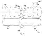
Figure 7 ] A top perspective view showing first and second rollers of a manufacturing device according to the second embodiment of the present invention. - Embodiments of a device and a method for manufacturing an uneven-thickness film according to the present invention will be described with reference to the drawings. In each figure, like parts are denoted by like reference numerals and the description thereof is omitted.
-
Figure 1 is a cross-sectional view of a molded body of an uneven-thickness film extruded by a manufacturing device and a method of a first embodiment, shown in a direction vertical to the extruding (longitudinal) direction. The moldedbody 120 consists of two molded sub-bodies 120'. The molded sub-body 120' comprises aflat portion 122 that has a uniform film thickness, an uneven-thickness portion 124 whose film thickness changes, and a connectingportion 128 whose film thickness is thinner than theflat portion 122. Preferably, the connectingportion 128 can be formed to have a substantially uniform film thickness between a disc-shapedportion 232 of afirst roller 230 and a column-shaped portion of asecond roller 240 which will be described later. The top surface of the molded body 120' is formed to rise on the uneven-thickness portion 124 side while the bottom surface of the molded body 120' is formed to be flat. The thickness (film thickness) of the uneven-thickness portion 124 decreases from thefirst side part 126 on the connectingportion 128 side towards thesecond side part 130 on theflat portion 122 side. Theside parts 126 of the two uneven-thickness portions 124 oppose to each other via the connectingportion 128. The connectingportion 128 is formed on the bottom surface side of the molded bodies 120'. -
Figure 2 is a perspective view showing a molded sub-body 120' obtained by cutting the moldedbody 120 of the uneven-thickness film shown inFigure 1 . The molded sub-body 120' is cut along thecut plane 128a of the connectingportion 128 parallel to the extruding direction, and also cut along two cutplanes 132 that is vertical to the extruding direction. - According to the first embodiment, the two molded sub-bodies 120' are integrally molded to be symmetrically arranged side by side such that the
side parts 126 thereof oppose each other as shown inFigure 1 . Alternatively, multiple molded bodies including these two molded sub-bodies 120' may integrally be molded to be arranged side by side by connecting theside parts 130 via connecting portions. The entire connectingportion 128 is cut off from the molded sub-body 120' to use the resultant as a light guide film. - Referring to
Figure 2 , theside part 126 serves as a light incident surface, theside part 130 serves as an end face, the slopedsurface 124a of the uneven-thickness portion 124 serves as a light-reflecting surface, and the upper planar surface of theflat portion 122 serves as a light emitting surface. The slopedsurface 124a as the light-reflecting surface is formed with a dot pattern that reflects light as will be described later. -
Figure 3 is a part perspective view of amanufacturing device 200 for molding the molded body of the uneven-thickness film shown inFigure 1 . Themanufacturing device 200 comprises adie 201 for accommodating and extruding a resin, a rectangular-shapedextrusion port 202 formed on thedie 201, afirst roller 230, asecond roller 240 and athird roller 250. The first andsecond rollers extrusion port 202, and arranged to sandwich apre-molded resin plate 110 extruded from theextrusion port 202. Thethird roller 250 is arranged next to thesecond roller 240. - With reference to
Figure 4 , the structures of thefirst roller 230 and thesecond roller 240 will be described. Thefirst roller 230 consists of a disc-shapedportion 232, a pair of truncated-cone-shapedportions 234 that sandwich the disc-shapedportion 232, and a pair of column-shapedportions 236 arranged outside the respective pair of truncated-cone-shapedportions 234. The respective portions of thefirst roller 230 are integrally arranged such that their rotation centers are positioned along the same axis. The pair of truncated-cone-shapedportions 234 are symmetrically arranged with respect to the disc-shapedportion 232 with the smaller-diameter faces 234a facing inside and the larger-diameter faces 234b facing outside. The diameter of the disc-shapedportion 232 is larger than the diameter of the larger-diameter face 234a of the truncated-cone-shapedportion 234. Thesecond roller 240 and thethird roller 250 are column-shaped portions as a whole, where the rotation center axis lines of the first tothird rollers portion 232 of thefirst roller 230 opposes the column-shaped portion of thesecond roller 240 are substantially parallel. Alternatively, thefirst roller 230 and thesecond roller 240 inFigures 3 and 4 may be arranged reversely. As shown inFigure 4 , the entire surface of the truncated-cone-shapedportion 234 comprises adot pattern 234c, by which a light-reflecting surface is formed on the uneven-thickness portion 124. Thesecond roller 240 andthird roller 250 have smooth surfaces. - A process of molding a molded body of an uneven-thickness film with the
manufacturing device 200 will be described. Themanufacturing device 200 heats a resin as a material of a light guide film to a temperature that allows the resin to have a low viscosity with a heating means (not shown), and extrudes this resin as aresin plate 110 from theextrusion port 202 of thedie 201. Theresin plate 110 extruded from theextrusion port 202 is guided to the triple rollers, i.e., the first tothird rollers second rollers resin plate 110 to make a moldedbody 120. Specifically, as theresin plate 110 passes through the first andsecond rollers portion 128 is formed between the disc-shapedportion 232 of thefirst roller 230 and thesecond roller 240, the uneven-thickness portion 124 is formed between the truncated-cone-shapedportion 234 of thefirst roller 230 and thesecond roller 240, and theflat portion 122 is formed between the column-shapedportion 236 of thefirst roller 230 and thesecond roller 240. With thedot pattern 234c of the truncated-cone-shapedportion 234, a dot pattern for light reflecting is formed on the resin plate. - Usually, the last
third roller 250 is controlled to have a temperature that is lower than the glass-transition temperature of the resin that forms the moldedbody 120. Accordingly, at least the surface of the moldedbody 120 is solidified when the moldedbody 120 leaves the triple rollers. The moldedbody 120 that left the triple rollers continues to advance while being further cooled in the air, is divided in the longitudinal direction at a cutter section (not shown) with a slitter, an edge knife or the like, and is further divided and cut in the plate width direction with a push-cutter or the like, thereby forming a light guide film. Thus dots can be formed simultaneously with the molding of the plastic panel (molded body 120). Depending on the thickness or the width of the connectingportion 128 of the thin film shown inFigure 1 , dividing in the longitudinal direction may be omitted, in which case the molded body may be split to make light guide films at the stage of assembling the light guide film into a product. Furthermore, in the first embodiment, the disc-shapedportion 232 shown inFigure 4 may be omitted. In this case, the center part of the thickness of the moldedbody 120 of the uneven-thickness film can be cut to make light guide films. -
Figure 5 is a cross-sectional view of a molded body of an uneven-thickness film extruded by a manufacturing device and a method of the second embodiment, shown in a direction vertical to the extruding direction. The moldedbody 220 consists of two molded sub-bodies 220'. The molded sub-body 220' comprises aflat portion 222 that has a uniform film thickness, an uneven-thickness portion 224 whose film thickness changes, and a connectingportion 228 whose film thickness is thinner than theflat portion 222. The top surface of the molded body 220' is formed to rise on the uneven-thickness portion 224 side while the bottom surface of the molded body 220' is formed to be flat. The thickness (film thickness) of the uneven-thickness portion 224 decreases from thefirst side part 226 on the connectingportion 228 side towards thesecond side part 230 on theflat portion 232 side. Theside parts 126 of the two uneven-thickness portions 224 oppose to each other via the connectingportion 228. The connectingportion 228 is formed on the top surface side of the rising molded body 120'. Preferably, the connectingportion 228 can be formed to have a substantially uniform film thickness between a disc-shapedportion 332 of thefirst roller 330 and a small-diameter portion 342 of thesecond roller 340 which will be described later. -
Figure 6 is a perspective view showing the molded sub-body 220' obtained by cutting the moldedbody 220 of the uneven-thickness film shown inFigure 5 . The molded sub-bodies 220' are cut along acut plane 228a of the connectingportion 228 that is parallel to the extruding direction, and also cut along two cutplanes 232 that are vertical to the extruding direction. - According to the second embodiment, the two molded sub-bodies 220' are integrally molded to be symmetrically arranged side by side such that the
side parts 226 thereof oppose each other as shown inFigure 5 . Alternatively, multiple molded bodies including these two molded sub-bodies 220' may integrally be molded to be arranged side by side by connecting theside parts 230 via connecting portions. The entire connectingportion 228 is cut off from the molded sub-body 220' to use the resultant as a light guide film. - Referring to
Figure 6 , theside part 226 serves as a light incident surface, theside part 230 serves as an end face, the slopedsurface 224a of the uneven-thickness portion 224 serves as a light-reflecting surface, and the upper planar surface of theflat portion 232 serves as a light emitting surface 232a. The slopedsurface 224a as the light-reflecting surface is formed with a dot pattern. - In the second embodiment, a manufacturing device for molding a molded body of an uneven-thickness film is similar to the
manufacturing device 200 of the first embodiment (Figure 3 ). Only the first roller and the second roller of the manufacturing device of the second embodiment have structures different from those of themanufacturing device 200. Hereinafter, thefirst roller 330 and thesecond roller 340 used for the manufacturing device of the second embodiment will be described. - As shown in
Figure 7 , thefirst roller 330 consists of a disc-shapedportion 332, and a pair of column-shapedportions 334 that sandwich the disc-shapedportion 332. The respective portions of thefirst roller 330 are integrally arranged such that their rotation centers are positioned along the same axis. The diameter of the disc-shapedportion 332 is larger than the diameter of the column-shapedportion 334. Thesecond roller 340 consists of a disc-shaped small-diameter portion 342, a pair of truncated-cone-shapedportions 344 sandwiching the small-diameter portion 342, and a pair of column-shapedportions 346 arranged outside the pair of truncated-cone-shapedportions 344, respectively. The pair of truncated-cone-shapedportions 334 are symmetrically arranged to sandwich the small-diameter portion 342 with the smaller-diameter faces 334a facing inside and the larger-diameter faces 334b facing outside. The diameter of the smaller-diameter face 344a of the truncated-cone-shapedportion 344 is the same as the diameter of the small-diameter portion 342. The small-diameter portion 342 gently connects with the truncated-cone-shapedportion 344 on the smaller-diameter face 344a side. The diameter of the larger-diameter face 344b of the truncated-cone-shapedportion 344 is the same as the diameter of the column-shapedportion 346. Preferably, the portion where the disc-shapedportion 332 of thefirst roller 330 opposes the small-diameter portion 342 of thesecond roller 340 may be substantially parallel. Alternatively, thefirst roller 330 and thesecond roller 340 may be arranged reversely. Although it is not shown, the entire surface of the truncated-cone-shapedportion 334 comprises a dot pattern. Thefirst roller 330 has a smooth surface. - A process of molding a molded body of an uneven-thickness film according to the second embodiment will be described. Steps that are the same as the molding steps of the first embodiment will be omitted. A
resin plate 110 extruded from anextrusion port 202 of adie 201 is guided to triple rollers, i.e., the first tothird rollers resin plate 110 passes through the first andsecond rollers portion 228 is formed between the disc-shapedportion 332 of thefirst roller 340 and the small-diameter portion 342 of thesecond roller 340, an uneven-thickness portion 224 is formed between the inner part of the column-shapedportion 334 of thefirst roller 330 and the truncated-cone-shapedportion 344 of thesecond roller 340, and aflat portion 222 is formed between the outer part of the column-shapedportion 334 of thefirst roller 330 and the column-shapedportion 346 of thesecond roller 340. With the dot pattern of the truncated-cone-shapedportion 334, a dot pattern is formed on the resin plate. In the second embodiment, the disc-shapedportion 332 shown inFigure 7 may be omitted. In this case, the center part of the thickness of the moldedbody 120 of the uneven-thickness film can be cut to make light guide films. - Although each embodiment was described using triple rollers, the number of rollers is not limited to three, and may be two, i.e., the first roller and the second roller, or four or more. In each embodiment, a transparent resin such as an acrylic resin, a polycarbonate resin or the like is used as an uneven-thickness film that is used for manufacturing a light guide film. In each embodiment, a polarizing element may be embossed onto the bottom surface of the molded
body -
- 120
- Molded body
- 124
- Uneven-thickness portion
- 122
- Flat portion
- 128
- Connecting portion
- 200
- Manufacturing device
- 201
- Die
- 202
- Extrusion port
- 230
- First roller
- 240
- Second roller
- 250
- Third roller
- 232
- Disc-shaped portion
- 234
- Truncated-cone-shaped portion
- 236
- Column-shaped portion
- 220
- Molded body
- 224
- Uneven-thickness portion
- 222
- Flat portion
- 228
- Connecting portion
- 330
- First roller
- 340
- Second roller
- 332
- Disc-shaped portion
- 334
- Column-shaped portion
- 342
- Small-diameter portion
- 344
- Truncated-cone-shaped portion
- 346
- Column-shaped portion
Claims (23)
- A device for manufacturing an uneven-thickness film comprising a first roller and a second roller for molding the uneven-thickness film, wherein:the first roller comprises a truncated-cone-shaped portion and a disc-shaped portion; wherein the diameter of the disc-shaped portion is larger than the diameter of the larger-diameter face of the truncated-cone-shaped portion; and the second roller comprises a column-shaped portion.
- The manufacturing device according to Claim 1, wherein the manufacturing device forms a thick part to the molded body of the uneven-thickness film between the truncated-cone-shaped portion of the first roller and the column-shaped portion of the second roller, and forms a thin connecting portion to the molded body between the disc-shaped portion of the first roller and the column-shaped portion of the second roller.
- The manufacturing device according to Claim 1 or 2, wherein portions where the disc-shaped portion of the first roller opposes the column-shaped portion of the second roller are substantially parallel.
- The manufacturing device according to Claim 2 or 3, wherein the truncated-cone-shaped portion is a pair of truncated-cone-shaped portions, and the pair of truncated-cone-shaped portions are symmetrically arranged to sandwich the disc-shaped portion.
- The manufacturing device according to any one of Claims 1-4, wherein the portions constituting the first roller are integrally arranged on the same axis.
- The manufacturing device according to any one of Claims 2-5, wherein the disc-shaped portion connects with the smaller-diameter face of the truncated-cone-shaped portion.
- The manufacturing device according to any one of Claims 1-6, wherein the first roller further comprises a column-shaped portion.
- The manufacturing device according to Claim 7, wherein the column-shaped portion of the first roller connects with the larger-diameter face of the truncated-cone-shaped portion of the first roller.
- A device for manufacturing an uneven-thickness film comprising a first roller and a second roller for molding the uneven-thickness film, wherein:the first roller comprises a column-shaped portion and a disc-shaped portion; the second roller comprises a truncated-cone-shaped portion and a disc-shaped small-diameter portion; and the small-diameter portion gently connects with the truncated-cone-shaped portion on the smaller-diameter face side.
- The manufacturing device according to Claim 9, wherein the manufacturing device forms a thick part to the molded body of the uneven-thickness film between the column-shaped portion of the first roller and the truncated-cone-shaped portion of the second roller, and forms a thin connecting portion to the molded body between the disc-shaped portion of the first roller and the small-diameter portion of the second roller.
- The manufacturing device according to Claim 9 or 10, wherein portions where the disc-shaped portion of the first roller opposes the small-diameter portion of the second roller are substantially parallel.
- The manufacturing device according to any one of Claims 9-11, wherein the truncated-cone-shaped portion is a pair of truncated-cone-shaped portions, and the pair of truncated-cone-shaped portions are symmetrically arranged to sandwich the small-diameter portion.
- The manufacturing device according to any one of Claims 9-12, wherein the portions constituting the first roller or the second roller are integrally arranged on the same axis.
- The manufacturing device according to any one of Claims 9-13, wherein the small-diameter portion connects with the smaller-diameter face of the truncated-cone-shaped portion.
- The manufacturing device according to any one of Claims 9-14, wherein the second roller further comprises a column-shaped portion.
- The manufacturing device according to Claim 15, wherein the column-shaped portion of the second roller is connected with the larger-diameter face of the truncated-cone-shaped portion of the second roller.
- The manufacturing device according to either one of Claims 2 and 10, wherein the thick part of the molded body is formed such that the film thickness thereof changes from one side part to the other side part that are parallel to the extruding direction.
- The manufacturing device according to any one of Claims 1-16, wherein the surface of the truncated-cone-shaped portion comprises a dot pattern.
- The manufacturing device according to any one of Claims 1-18, comprising a cutter section for cutting the molded body molded with the first roller and the second roller.
- The manufacturing device according to any one of Claims 2, 10 and 17, wherein the molded body of the uneven-thickness film consists of multiple molded sub-bodies which are connected via the connecting portions.
- A method for manufacturing an uneven-thickness film using a first roller and a second roller for molding the uneven-thickness film, wherein:the first roller comprises a truncated-cone-shaped portion and a disc-shaped portion; and the diameter of the disc-shaped portion is larger than the diameter of the larger-diameter face of the truncated-cone-shaped portion; and the second roller comprises a column-shaped portion,the method comprising the steps of:forming a thick part to the molded body of the uneven-thickness film between the truncated-cone-shaped portion of the first roller and the column-shaped portion of the second roller; andforming a thin connecting portion to the molded body between the disc-shaped portion of the first roller and the column-shaped portion of the second roller.
- A method for manufacturing an uneven-thickness film using a first roller and a second roller for molding the uneven-thickness film, wherein:the first roller comprises a column-shaped portion and a disc-shaped portion; the second roller comprises a truncated-cone-shaped portion and a small-diameter portion; and the diameter of the small-diameter portion is smaller than the diameter of the smaller-diameter face of the truncated-cone-shaped portion,the method comprising the steps of:forming a thick part to the molded body of the uneven-thickness film between the column-shaped portion of the first roller and the truncated-cone-shaped portion of the second roller; andforming a thin connecting portion to the molded body between the disc-shaped portion of the first roller and the small-diameter portion of the second roller.
- The manufacturing method according to Claim 21 or 22, wherein the connecting portion is formed to have a substantially uniform thickness.
Priority Applications (1)
| Application Number | Priority Date | Filing Date | Title |
|---|---|---|---|
| EP18155726.5A EP3338986B1 (en) | 2013-12-20 | 2014-11-20 | Device for manufacturing uneven-thickness film, and method for manufacturing uneven-thickness film |
Applications Claiming Priority (2)
| Application Number | Priority Date | Filing Date | Title |
|---|---|---|---|
| JP2013263393 | 2013-12-20 | ||
| PCT/JP2014/080827 WO2015093227A1 (en) | 2013-12-20 | 2014-11-20 | Device for manufacturing uneven-thickness film, and method for manufacturing uneven-thickness film |
Related Child Applications (2)
| Application Number | Title | Priority Date | Filing Date |
|---|---|---|---|
| EP18155726.5A Division EP3338986B1 (en) | 2013-12-20 | 2014-11-20 | Device for manufacturing uneven-thickness film, and method for manufacturing uneven-thickness film |
| EP18155726.5A Division-Into EP3338986B1 (en) | 2013-12-20 | 2014-11-20 | Device for manufacturing uneven-thickness film, and method for manufacturing uneven-thickness film |
Publications (3)
| Publication Number | Publication Date |
|---|---|
| EP3085513A1 true EP3085513A1 (en) | 2016-10-26 |
| EP3085513A4 EP3085513A4 (en) | 2017-08-30 |
| EP3085513B1 EP3085513B1 (en) | 2020-04-22 |
Family
ID=53402582
Family Applications (2)
| Application Number | Title | Priority Date | Filing Date |
|---|---|---|---|
| EP14871003.1A Active EP3085513B1 (en) | 2013-12-20 | 2014-11-20 | Device for manufacturing uneven-thickness film, and method for manufacturing uneven-thickness film |
| EP18155726.5A Active EP3338986B1 (en) | 2013-12-20 | 2014-11-20 | Device for manufacturing uneven-thickness film, and method for manufacturing uneven-thickness film |
Family Applications After (1)
| Application Number | Title | Priority Date | Filing Date |
|---|---|---|---|
| EP18155726.5A Active EP3338986B1 (en) | 2013-12-20 | 2014-11-20 | Device for manufacturing uneven-thickness film, and method for manufacturing uneven-thickness film |
Country Status (7)
| Country | Link |
|---|---|
| US (1) | US10427335B2 (en) |
| EP (2) | EP3085513B1 (en) |
| JP (1) | JP6618363B2 (en) |
| KR (1) | KR102293964B1 (en) |
| CN (1) | CN105829061B (en) |
| TW (1) | TWI647088B (en) |
| WO (1) | WO2015093227A1 (en) |
Cited By (1)
| Publication number | Priority date | Publication date | Assignee | Title |
|---|---|---|---|---|
| WO2020249547A1 (en) * | 2019-06-12 | 2020-12-17 | Battenfeld-Cincinnati Germany Gmbh | Apparatus and method for producing a plastic web |
Families Citing this family (6)
| Publication number | Priority date | Publication date | Assignee | Title |
|---|---|---|---|---|
| JP6571412B2 (en) | 2015-06-29 | 2019-09-04 | 東芝機械株式会社 | Optical sheet forming apparatus and optical sheet forming method |
| DE102017125836A1 (en) * | 2017-11-06 | 2019-05-09 | Brückner Maschinenbau GmbH & Co. KG | chill roll |
| US20190184656A1 (en) * | 2017-12-19 | 2019-06-20 | The Goodyear Tire & Rubber Company | Strip lamination method and apparatus |
| JP6821757B2 (en) * | 2019-08-07 | 2021-01-27 | 芝浦機械株式会社 | Optical sheet molding equipment, optical sheet molding method |
| JP7364458B2 (en) * | 2019-12-23 | 2023-10-18 | 住友理工株式会社 | Resin filler tube and its manufacturing method |
| CN112497612A (en) * | 2020-10-28 | 2021-03-16 | 张怀文 | Four-roller plastic calender with wider application range |
Family Cites Families (17)
| Publication number | Priority date | Publication date | Assignee | Title |
|---|---|---|---|---|
| US5030079A (en) * | 1989-10-27 | 1991-07-09 | The Goodyear Tire & Rubber Company | Roller die extrusion and calendering apparatus |
| US5174845A (en) * | 1990-05-14 | 1992-12-29 | Thiokol Corporation | Insulation wrapping strip with variable configuration |
| JPH04353894A (en) | 1991-05-31 | 1992-12-08 | Ohtsu Tire & Rubber Co Ltd :The | Photoconduction plate for edge light type electric decoration signboard |
| JP3410608B2 (en) | 1995-06-16 | 2003-05-26 | 株式会社クラレ | Manufacturing method of light guide |
| JP2004082359A (en) * | 2002-08-23 | 2004-03-18 | Columbia Music Entertainment Inc | Manufacturing method for thickness irregular plate material using extruder |
| JP2006059763A (en) | 2004-08-23 | 2006-03-02 | Sumitomo Rubber Ind Ltd | Sidelight type surface lighting device |
| US7186110B2 (en) * | 2004-09-17 | 2007-03-06 | Francis Chung Hwa Pan | Apparatus of making wedged plates |
| JP2006088649A (en) * | 2004-09-27 | 2006-04-06 | Chung-Hua Pan | Wedge plate forming device |
| US20090014116A1 (en) * | 2005-03-16 | 2009-01-15 | Fujifilm Corporation | Method of producing resin sheet |
| US20090071598A1 (en) | 2005-03-23 | 2009-03-19 | Fujifilm Corporation | Method of producing resin sheet |
| JP5153152B2 (en) | 2007-01-31 | 2013-02-27 | 富士フイルム株式会社 | Surface lighting device |
| KR20100014681A (en) | 2007-03-30 | 2010-02-10 | 후지필름 가부시키가이샤 | Method and apparatus for manufacturing uneven thickness resin sheet |
| JP2009040009A (en) * | 2007-08-10 | 2009-02-26 | Fujifilm Corp | Manufacturing method and apparatus for uneven thickness resin sheet |
| JP2009083309A (en) * | 2007-09-28 | 2009-04-23 | Fujifilm Corp | Small sheet manufacturing method |
| JP2009220443A (en) * | 2008-03-17 | 2009-10-01 | Fujifilm Corp | Manufacturing method of uneven-thickness resin sheet |
| US8086745B2 (en) * | 2008-08-29 | 2011-12-27 | Fuji Xerox Co., Ltd | Graphical system and method for user authentication |
| JP2010058437A (en) * | 2008-09-05 | 2010-03-18 | Fujifilm Corp | Method of manufacturing resin sheet |
-
2014
- 2014-11-20 EP EP14871003.1A patent/EP3085513B1/en active Active
- 2014-11-20 US US15/103,512 patent/US10427335B2/en active Active
- 2014-11-20 EP EP18155726.5A patent/EP3338986B1/en active Active
- 2014-11-20 WO PCT/JP2014/080827 patent/WO2015093227A1/en not_active Ceased
- 2014-11-20 KR KR1020167018725A patent/KR102293964B1/en active Active
- 2014-11-20 CN CN201480068641.9A patent/CN105829061B/en active Active
- 2014-11-20 JP JP2015553442A patent/JP6618363B2/en active Active
- 2014-12-04 TW TW103142178A patent/TWI647088B/en active
Cited By (1)
| Publication number | Priority date | Publication date | Assignee | Title |
|---|---|---|---|---|
| WO2020249547A1 (en) * | 2019-06-12 | 2020-12-17 | Battenfeld-Cincinnati Germany Gmbh | Apparatus and method for producing a plastic web |
Also Published As
| Publication number | Publication date |
|---|---|
| JP6618363B2 (en) | 2019-12-11 |
| EP3085513A4 (en) | 2017-08-30 |
| CN105829061A (en) | 2016-08-03 |
| EP3338986B1 (en) | 2020-07-08 |
| EP3085513B1 (en) | 2020-04-22 |
| KR102293964B1 (en) | 2021-08-25 |
| WO2015093227A1 (en) | 2015-06-25 |
| US20160311137A1 (en) | 2016-10-27 |
| TWI647088B (en) | 2019-01-11 |
| US10427335B2 (en) | 2019-10-01 |
| TW201534455A (en) | 2015-09-16 |
| EP3338986A1 (en) | 2018-06-27 |
| JPWO2015093227A1 (en) | 2017-03-16 |
| KR20160101029A (en) | 2016-08-24 |
| CN105829061B (en) | 2019-03-05 |
Similar Documents
| Publication | Publication Date | Title |
|---|---|---|
| EP3085513B1 (en) | Device for manufacturing uneven-thickness film, and method for manufacturing uneven-thickness film | |
| US8851734B2 (en) | Light guiding film having light extraction features | |
| JP2009220555A (en) | Manufacturing method of surface pattern transfer resin sheet and its manufacturing apparatus | |
| US11472086B2 (en) | Optical sheet forming device and optical sheet forming method | |
| CN104122618A (en) | Composite light guide plate and manufacturing method thereof | |
| TW201202766A (en) | Thin double-sided light guide plate | |
| KR20110044148A (en) | Manufacturing method of surface shape transfer resin sheet | |
| CN102455447A (en) | Light diffusion plate and its manufacturing method, surface light source device and liquid crystal display device | |
| US10035289B2 (en) | Manufacturing apparatus for film of non-uniform thickness and manufacturing method for film of non-uniform thickness | |
| JP5648075B2 (en) | Method for manufacturing shape transfer resin sheet and resin sheet | |
| JP2014044912A (en) | Method for manufacturing resin sheet | |
| WO2011115111A1 (en) | Method for manufacturing optical sheet | |
| CN202813209U (en) | Light distributing patch for backlight plate module and backlight module using light distributing patch | |
| JP2017001250A (en) | Light guide resin film | |
| CN102310560A (en) | The manufacturing approach of resin sheet | |
| JP2012144033A (en) | Method of manufacturing resin sheet | |
| JP2012040846A (en) | Method of manufacturing light control plate | |
| JP2014038800A (en) | Method for manufacturing light guide plate |
Legal Events
| Date | Code | Title | Description |
|---|---|---|---|
| PUAI | Public reference made under article 153(3) epc to a published international application that has entered the european phase |
Free format text: ORIGINAL CODE: 0009012 |
|
| 17P | Request for examination filed |
Effective date: 20160628 |
|
| AK | Designated contracting states |
Kind code of ref document: A1 Designated state(s): AL AT BE BG CH CY CZ DE DK EE ES FI FR GB GR HR HU IE IS IT LI LT LU LV MC MK MT NL NO PL PT RO RS SE SI SK SM TR |
|
| AX | Request for extension of the european patent |
Extension state: BA ME |
|
| DAX | Request for extension of the european patent (deleted) | ||
| RIC1 | Information provided on ipc code assigned before grant |
Ipc: B29C 47/14 20060101ALI20170720BHEP Ipc: B29L 7/00 20060101ALN20170720BHEP Ipc: F21V 8/00 20060101ALI20170720BHEP Ipc: B29C 47/00 20060101ALI20170720BHEP Ipc: B29C 43/46 20060101AFI20170720BHEP |
|
| A4 | Supplementary search report drawn up and despatched |
Effective date: 20170731 |
|
| STAA | Information on the status of an ep patent application or granted ep patent |
Free format text: STATUS: EXAMINATION IS IN PROGRESS |
|
| 17Q | First examination report despatched |
Effective date: 20190220 |
|
| REG | Reference to a national code |
Ref country code: DE Ref legal event code: R079 Ref document number: 602014064302 Country of ref document: DE Free format text: PREVIOUS MAIN CLASS: B29C0047880000 Ipc: B29C0043460000 |
|
| GRAP | Despatch of communication of intention to grant a patent |
Free format text: ORIGINAL CODE: EPIDOSNIGR1 |
|
| STAA | Information on the status of an ep patent application or granted ep patent |
Free format text: STATUS: GRANT OF PATENT IS INTENDED |
|
| RIC1 | Information provided on ipc code assigned before grant |
Ipc: B29C 48/00 20190101ALI20191121BHEP Ipc: B29C 48/08 20190101ALI20191121BHEP Ipc: B29K 69/00 20060101ALN20191121BHEP Ipc: B29C 48/12 20190101ALI20191121BHEP Ipc: B29C 43/24 20060101ALN20191121BHEP Ipc: F21V 8/00 20060101ALI20191121BHEP Ipc: B29C 43/46 20060101AFI20191121BHEP Ipc: B29L 7/00 20060101ALN20191121BHEP Ipc: B29L 11/00 20060101ALN20191121BHEP |
|
| RIC1 | Information provided on ipc code assigned before grant |
Ipc: B29C 48/08 20190101ALI20191202BHEP Ipc: F21V 8/00 20060101ALI20191202BHEP Ipc: B29L 11/00 20060101ALN20191202BHEP Ipc: B29L 7/00 20060101ALN20191202BHEP Ipc: B29C 43/46 20060101AFI20191202BHEP Ipc: B29C 43/24 20060101ALN20191202BHEP Ipc: B29C 48/12 20190101ALI20191202BHEP Ipc: B29C 48/00 20190101ALI20191202BHEP Ipc: B29K 69/00 20060101ALN20191202BHEP |
|
| INTG | Intention to grant announced |
Effective date: 20191217 |
|
| RIN1 | Information on inventor provided before grant (corrected) |
Inventor name: AKITA, REIKI |
|
| GRAS | Grant fee paid |
Free format text: ORIGINAL CODE: EPIDOSNIGR3 |
|
| GRAA | (expected) grant |
Free format text: ORIGINAL CODE: 0009210 |
|
| STAA | Information on the status of an ep patent application or granted ep patent |
Free format text: STATUS: THE PATENT HAS BEEN GRANTED |
|
| AK | Designated contracting states |
Kind code of ref document: B1 Designated state(s): AL AT BE BG CH CY CZ DE DK EE ES FI FR GB GR HR HU IE IS IT LI LT LU LV MC MK MT NL NO PL PT RO RS SE SI SK SM TR |
|
| REG | Reference to a national code |
Ref country code: CH Ref legal event code: EP |
|
| REG | Reference to a national code |
Ref country code: IE Ref legal event code: FG4D |
|
| REG | Reference to a national code |
Ref country code: DE Ref legal event code: R096 Ref document number: 602014064302 Country of ref document: DE |
|
| REG | Reference to a national code |
Ref country code: AT Ref legal event code: REF Ref document number: 1259492 Country of ref document: AT Kind code of ref document: T Effective date: 20200515 |
|
| REG | Reference to a national code |
Ref country code: LT Ref legal event code: MG4D |
|
| REG | Reference to a national code |
Ref country code: NL Ref legal event code: MP Effective date: 20200422 |
|
| PG25 | Lapsed in a contracting state [announced via postgrant information from national office to epo] |
Ref country code: GR Free format text: LAPSE BECAUSE OF FAILURE TO SUBMIT A TRANSLATION OF THE DESCRIPTION OR TO PAY THE FEE WITHIN THE PRESCRIBED TIME-LIMIT Effective date: 20200723 Ref country code: FI Free format text: LAPSE BECAUSE OF FAILURE TO SUBMIT A TRANSLATION OF THE DESCRIPTION OR TO PAY THE FEE WITHIN THE PRESCRIBED TIME-LIMIT Effective date: 20200422 Ref country code: LT Free format text: LAPSE BECAUSE OF FAILURE TO SUBMIT A TRANSLATION OF THE DESCRIPTION OR TO PAY THE FEE WITHIN THE PRESCRIBED TIME-LIMIT Effective date: 20200422 Ref country code: IS Free format text: LAPSE BECAUSE OF FAILURE TO SUBMIT A TRANSLATION OF THE DESCRIPTION OR TO PAY THE FEE WITHIN THE PRESCRIBED TIME-LIMIT Effective date: 20200822 Ref country code: SE Free format text: LAPSE BECAUSE OF FAILURE TO SUBMIT A TRANSLATION OF THE DESCRIPTION OR TO PAY THE FEE WITHIN THE PRESCRIBED TIME-LIMIT Effective date: 20200422 Ref country code: NO Free format text: LAPSE BECAUSE OF FAILURE TO SUBMIT A TRANSLATION OF THE DESCRIPTION OR TO PAY THE FEE WITHIN THE PRESCRIBED TIME-LIMIT Effective date: 20200722 Ref country code: NL Free format text: LAPSE BECAUSE OF FAILURE TO SUBMIT A TRANSLATION OF THE DESCRIPTION OR TO PAY THE FEE WITHIN THE PRESCRIBED TIME-LIMIT Effective date: 20200422 Ref country code: PT Free format text: LAPSE BECAUSE OF FAILURE TO SUBMIT A TRANSLATION OF THE DESCRIPTION OR TO PAY THE FEE WITHIN THE PRESCRIBED TIME-LIMIT Effective date: 20200824 |
|
| REG | Reference to a national code |
Ref country code: AT Ref legal event code: MK05 Ref document number: 1259492 Country of ref document: AT Kind code of ref document: T Effective date: 20200422 |
|
| PG25 | Lapsed in a contracting state [announced via postgrant information from national office to epo] |
Ref country code: HR Free format text: LAPSE BECAUSE OF FAILURE TO SUBMIT A TRANSLATION OF THE DESCRIPTION OR TO PAY THE FEE WITHIN THE PRESCRIBED TIME-LIMIT Effective date: 20200422 Ref country code: RS Free format text: LAPSE BECAUSE OF FAILURE TO SUBMIT A TRANSLATION OF THE DESCRIPTION OR TO PAY THE FEE WITHIN THE PRESCRIBED TIME-LIMIT Effective date: 20200422 Ref country code: BG Free format text: LAPSE BECAUSE OF FAILURE TO SUBMIT A TRANSLATION OF THE DESCRIPTION OR TO PAY THE FEE WITHIN THE PRESCRIBED TIME-LIMIT Effective date: 20200722 Ref country code: LV Free format text: LAPSE BECAUSE OF FAILURE TO SUBMIT A TRANSLATION OF THE DESCRIPTION OR TO PAY THE FEE WITHIN THE PRESCRIBED TIME-LIMIT Effective date: 20200422 |
|
| PG25 | Lapsed in a contracting state [announced via postgrant information from national office to epo] |
Ref country code: AL Free format text: LAPSE BECAUSE OF FAILURE TO SUBMIT A TRANSLATION OF THE DESCRIPTION OR TO PAY THE FEE WITHIN THE PRESCRIBED TIME-LIMIT Effective date: 20200422 |
|
| REG | Reference to a national code |
Ref country code: DE Ref legal event code: R097 Ref document number: 602014064302 Country of ref document: DE |
|
| PG25 | Lapsed in a contracting state [announced via postgrant information from national office to epo] |
Ref country code: ES Free format text: LAPSE BECAUSE OF FAILURE TO SUBMIT A TRANSLATION OF THE DESCRIPTION OR TO PAY THE FEE WITHIN THE PRESCRIBED TIME-LIMIT Effective date: 20200422 Ref country code: DK Free format text: LAPSE BECAUSE OF FAILURE TO SUBMIT A TRANSLATION OF THE DESCRIPTION OR TO PAY THE FEE WITHIN THE PRESCRIBED TIME-LIMIT Effective date: 20200422 Ref country code: EE Free format text: LAPSE BECAUSE OF FAILURE TO SUBMIT A TRANSLATION OF THE DESCRIPTION OR TO PAY THE FEE WITHIN THE PRESCRIBED TIME-LIMIT Effective date: 20200422 Ref country code: SM Free format text: LAPSE BECAUSE OF FAILURE TO SUBMIT A TRANSLATION OF THE DESCRIPTION OR TO PAY THE FEE WITHIN THE PRESCRIBED TIME-LIMIT Effective date: 20200422 Ref country code: IT Free format text: LAPSE BECAUSE OF FAILURE TO SUBMIT A TRANSLATION OF THE DESCRIPTION OR TO PAY THE FEE WITHIN THE PRESCRIBED TIME-LIMIT Effective date: 20200422 Ref country code: CZ Free format text: LAPSE BECAUSE OF FAILURE TO SUBMIT A TRANSLATION OF THE DESCRIPTION OR TO PAY THE FEE WITHIN THE PRESCRIBED TIME-LIMIT Effective date: 20200422 Ref country code: AT Free format text: LAPSE BECAUSE OF FAILURE TO SUBMIT A TRANSLATION OF THE DESCRIPTION OR TO PAY THE FEE WITHIN THE PRESCRIBED TIME-LIMIT Effective date: 20200422 Ref country code: RO Free format text: LAPSE BECAUSE OF FAILURE TO SUBMIT A TRANSLATION OF THE DESCRIPTION OR TO PAY THE FEE WITHIN THE PRESCRIBED TIME-LIMIT Effective date: 20200422 |
|
| PG25 | Lapsed in a contracting state [announced via postgrant information from national office to epo] |
Ref country code: PL Free format text: LAPSE BECAUSE OF FAILURE TO SUBMIT A TRANSLATION OF THE DESCRIPTION OR TO PAY THE FEE WITHIN THE PRESCRIBED TIME-LIMIT Effective date: 20200422 Ref country code: SK Free format text: LAPSE BECAUSE OF FAILURE TO SUBMIT A TRANSLATION OF THE DESCRIPTION OR TO PAY THE FEE WITHIN THE PRESCRIBED TIME-LIMIT Effective date: 20200422 |
|
| PLBE | No opposition filed within time limit |
Free format text: ORIGINAL CODE: 0009261 |
|
| STAA | Information on the status of an ep patent application or granted ep patent |
Free format text: STATUS: NO OPPOSITION FILED WITHIN TIME LIMIT |
|
| 26N | No opposition filed |
Effective date: 20210125 |
|
| PG25 | Lapsed in a contracting state [announced via postgrant information from national office to epo] |
Ref country code: SI Free format text: LAPSE BECAUSE OF FAILURE TO SUBMIT A TRANSLATION OF THE DESCRIPTION OR TO PAY THE FEE WITHIN THE PRESCRIBED TIME-LIMIT Effective date: 20200422 |
|
| PG25 | Lapsed in a contracting state [announced via postgrant information from national office to epo] |
Ref country code: MC Free format text: LAPSE BECAUSE OF FAILURE TO SUBMIT A TRANSLATION OF THE DESCRIPTION OR TO PAY THE FEE WITHIN THE PRESCRIBED TIME-LIMIT Effective date: 20200422 |
|
| REG | Reference to a national code |
Ref country code: CH Ref legal event code: PL |
|
| GBPC | Gb: european patent ceased through non-payment of renewal fee |
Effective date: 20201120 |
|
| PG25 | Lapsed in a contracting state [announced via postgrant information from national office to epo] |
Ref country code: LU Free format text: LAPSE BECAUSE OF NON-PAYMENT OF DUE FEES Effective date: 20201120 |
|
| REG | Reference to a national code |
Ref country code: BE Ref legal event code: MM Effective date: 20201130 |
|
| PG25 | Lapsed in a contracting state [announced via postgrant information from national office to epo] |
Ref country code: LI Free format text: LAPSE BECAUSE OF NON-PAYMENT OF DUE FEES Effective date: 20201130 Ref country code: CH Free format text: LAPSE BECAUSE OF NON-PAYMENT OF DUE FEES Effective date: 20201130 |
|
| PG25 | Lapsed in a contracting state [announced via postgrant information from national office to epo] |
Ref country code: IE Free format text: LAPSE BECAUSE OF NON-PAYMENT OF DUE FEES Effective date: 20201120 Ref country code: FR Free format text: LAPSE BECAUSE OF NON-PAYMENT OF DUE FEES Effective date: 20201130 |
|
| PG25 | Lapsed in a contracting state [announced via postgrant information from national office to epo] |
Ref country code: GB Free format text: LAPSE BECAUSE OF NON-PAYMENT OF DUE FEES Effective date: 20201120 |
|
| PG25 | Lapsed in a contracting state [announced via postgrant information from national office to epo] |
Ref country code: TR Free format text: LAPSE BECAUSE OF FAILURE TO SUBMIT A TRANSLATION OF THE DESCRIPTION OR TO PAY THE FEE WITHIN THE PRESCRIBED TIME-LIMIT Effective date: 20200422 Ref country code: MT Free format text: LAPSE BECAUSE OF FAILURE TO SUBMIT A TRANSLATION OF THE DESCRIPTION OR TO PAY THE FEE WITHIN THE PRESCRIBED TIME-LIMIT Effective date: 20200422 Ref country code: CY Free format text: LAPSE BECAUSE OF FAILURE TO SUBMIT A TRANSLATION OF THE DESCRIPTION OR TO PAY THE FEE WITHIN THE PRESCRIBED TIME-LIMIT Effective date: 20200422 |
|
| PG25 | Lapsed in a contracting state [announced via postgrant information from national office to epo] |
Ref country code: MK Free format text: LAPSE BECAUSE OF FAILURE TO SUBMIT A TRANSLATION OF THE DESCRIPTION OR TO PAY THE FEE WITHIN THE PRESCRIBED TIME-LIMIT Effective date: 20200422 |
|
| PG25 | Lapsed in a contracting state [announced via postgrant information from national office to epo] |
Ref country code: BE Free format text: LAPSE BECAUSE OF NON-PAYMENT OF DUE FEES Effective date: 20201130 |
|
| PGFP | Annual fee paid to national office [announced via postgrant information from national office to epo] |
Ref country code: DE Payment date: 20241001 Year of fee payment: 11 |
|
| PG25 | Lapsed in a contracting state [announced via postgrant information from national office to epo] |
Ref country code: IS Free format text: LAPSE BECAUSE OF NON-PAYMENT OF DUE FEES Effective date: 20200822 |
|
| REG | Reference to a national code |
Ref country code: DE Ref legal event code: R119 Ref document number: 602014064302 Country of ref document: DE |